US5293875A - In-vivo measurement of end-tidal carbon monoxide concentration apparatus and methods - Google Patents
In-vivo measurement of end-tidal carbon monoxide concentration apparatus and methods Download PDFInfo
- Publication number
- US5293875A US5293875A US07/899,261 US89926192A US5293875A US 5293875 A US5293875 A US 5293875A US 89926192 A US89926192 A US 89926192A US 5293875 A US5293875 A US 5293875A
- Authority
- US
- United States
- Prior art keywords
- gas
- carbon monoxide
- concentration
- breath
- patient
- Prior art date
- Legal status (The legal status is an assumption and is not a legal conclusion. Google has not performed a legal analysis and makes no representation as to the accuracy of the status listed.)
- Expired - Fee Related
Links
Images


Classifications
-
- G—PHYSICS
- G01—MEASURING; TESTING
- G01N—INVESTIGATING OR ANALYSING MATERIALS BY DETERMINING THEIR CHEMICAL OR PHYSICAL PROPERTIES
- G01N33/00—Investigating or analysing materials by specific methods not covered by groups G01N1/00 - G01N31/00
- G01N33/48—Biological material, e.g. blood, urine; Haemocytometers
- G01N33/483—Physical analysis of biological material
- G01N33/497—Physical analysis of biological material of gaseous biological material, e.g. breath
-
- A—HUMAN NECESSITIES
- A61—MEDICAL OR VETERINARY SCIENCE; HYGIENE
- A61B—DIAGNOSIS; SURGERY; IDENTIFICATION
- A61B5/00—Measuring for diagnostic purposes; Identification of persons
- A61B5/08—Detecting, measuring or recording devices for evaluating the respiratory organs
- A61B5/083—Measuring rate of metabolism by using breath test, e.g. measuring rate of oxygen consumption
- A61B5/0836—Measuring rate of CO2 production
Definitions
- This invention relates to methods and apparatus for in-vivo, real time measurement of end-tidal carbon monoxide concentration in the exhaled breath, more particularly the determination of end-tidal carbon monoxide concentration in the breath of a newborn infant.
- carbon monoxide is a waste product produced in the breakdown of free hemoglobin within the blood.
- hemoglobin is contained within red blood cells and is stable.
- aging of red blood cells and certain disease processes produce hemolysis, i.e., the breakdown of the cell wall. This produces free hemoglobin which breaks down in the blood.
- the carbon monoxide that is produced by the breakdown of free hemoglobin is normally excreted in the breath.
- the carbon monoxide concentration in the breath is proportional to the difference in the concentration of carbon monoxide in the blood and the concentration of carbon monoxide in room air. This difference in concentration is proportional to the rate of hemolysis in the blood.
- the concentration of carbon monoxide in the end-tidal breath i.e., the gas that is last expelled each breath, is presumed to be at equilibrium with the concentration in the blood. This is because the end-tidal breath contains predominantly, if not exclusively, the gas expelled from the alveoli in the lungs, which gas was within the alveoli for a time generally sufficient to equilibrate with the blood.
- One method of analysis previously reported includes incrementally acquiring a sample of end-tidal breath and analyzing the acquired sample by mass spectroscopy or gas chromatography to determine the end-tidal carbon monoxide concentration.
- the sample is obtained by extracting from each of several successive breaths a portion of the apparent end-tidal breath using a syringe.
- the end-tidal portion of breath is determined by observing the chest movements of the infant. See, e.g., Vreman et al. U.S. Pat. No. 4,831,024.
- Another problem with this technique is that accurate assessment of the concentration difference in carbon monoxide requires obtaining good samples of end-tidal patient breath. This essentially requires that the patient have a regular, predictable breathing cycle. Thus, it can be difficult to obtain a good sample by watching chest wall movement, particularly for a newborn and for patients having irregular breathing cycles.
- Chemical electrochemical sensors capable of measuring carbon monoxide concentrations in the range of interest, 0 to 500 parts per million (ppm), are commercially available, e.g., model DragerSensor CO available from Dragerwerk, Lubeck, Germany.
- DragerSensor CO available from Dragerwerk, Lubeck, Germany.
- Another problem with such sensors is that the measurement dynamics of the sample gas transport through the gas permeable membrane and oxidation-reduction in the electrochemical cell results in a relatively slow response time such that discrete samples of the end-tidal breath must be obtained and analyzed to determine the end-tidal carbon monoxide concentration.
- an object of the present invention to provide improved non-invasive apparatus and methods for measuring carbon monoxide concentration in the end-tidal breath. It is another object to provide apparatus and methods that operate in real-time. It is another object to provide apparatus and methods for use in determining the rate of hemolysis from the concentration of end-tidal carbon monoxide.
- an apparatus, sampling methods, and analysis techniques for measuring the concentration of end-tidal carbon monoxide in breath, particularly in newborn and premature infants.
- the invention concerns determining the concentration of end-tidal carbon monoxide based on a measure of the room air carbon monoxide concentration, a measure of the average carbon monoxide concentration for a breath sample over a period of time, and a determined ratio of the end-tidal breath to inspired air for the sampled portion.
- the present invention is based in part on the discovery that accurate assessment of end-tidal carbon monoxide concentration may be obtained based on knowledge of the fraction of the gas sample that is end-tidal gas.
- the present invention is able to avoid selectively sampling small samples of end-tidal breath over successive respiratory cycles to obtain a sufficiently large end-tidal breath sample, which incremental sampling is problematic.
- the invention advantageously uses a conventional carbon monoxide detector, which has a response time that is not fast enough to distinguish carbon monoxide in end-tidal breath from carbon monoxide in inspired air, to derive the end-tidal carbon monoxide concentration in real-time.
- a conventional carbon monoxide detector can be used to obtain the average carbon monoxide concentration level during breathing, which average value can be related to the end-tidal value based on the determined ratio of end-tidal to inspired breath.
- the most common interfering substances from a sampled breath are removed from the sample by a consumable filtration medium so that these substances do not affect the measurement.
- the present invention also applies to gas components of exhaled breath other than carbon monoxide, which gas components cannot be directly monitored because of the slow response time of available gas detectors.
- One aspect of the present invention concerns using a second gas component of the breath, other than the first gas component whose concentration is being monitored, to determine the ratio of the end-tidal breath to inspired air.
- the relative concentration level of the second gas during respiration is monitored and the ratio or duty cycle of the end-tidal portion of the sensed concentration waveform relative to the inspired air is determined.
- a sensor for detecting the level (or concentration) of the second gas having a time response that is fast enough to distinguish the end-tidal breath concentration from the inspired air is preferably used.
- One suitable gas component is carbon dioxide, which has a large, distinctive change in concentration with breathing.
- gases may be used, e.g., hydrogen, oxygen, or some combination of gases, e.g., carbon dioxide and hydrogen.
- the determined end-tidal carbon monoxide concentration may be used by a physician or other suitable health care provider to evaluate the rate or relative level of hemolysis occurring in the infant.
- the evaluation is typically made by comparing the determined end-tidal carbon monoxide concentration to known or preselected standards. For example, when measured soon after birth, the end-tidal carbon monoxide range 0.6-1.9 ⁇ l/l is considered normal and the range above about 2 ⁇ l/l is considered at risk. Premature infants have both a higher risk of neonatal jaundice and a higher normal range of end-tidal carbon monoxide.
- the present invention provides a tool for predicting the likelihood that the determined level of hemolysis will lead to adverse consequences, such as jaundice and hyperbilirubinemia, which might not appear for several days.
- the apparatus and methods of the present invention provide for reliable detection and early treatment of the condition by an appropriate remedy, and for monitoring the efficacy of the treatment.
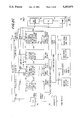
- FIG. 1 is a schematic block diagram of an apparatus for determining end-tidal carbon monoxide concentration in accordance with the present invention
- FIG. 2 is a diagram of a multipurpose microcontroller board for controlling the device in FIG. 1;
- FIGS. 2A-2D are macro flow diagrams for the overall, breath measurements, calibration, and data communication operations of the apparatus of FIG. 1;
- FIGS. 2E and 2F are circuit schematic diagrams for a signal conditioning amplifier and a power supply respectively, for interfacing the carbon monoxide sensor of FIG. 1 and the microcontroller circuit board of FIG. 2;
- FIGS. 3A and 3B are graphical illustrations of measurements of carbon monoxide carbon dioxide concentrations acquired using the device of FIG. 1;
- FIGS. 4A and 4B are graphical illustrations of the carbon monoxide and carbon dioxide concentrations in a representative breath flow.
- FIG. 5 is a schematic block diagram of an apparatus for determining end-tidal carbon monoxide concentration in accordance with alternate embodiments of the present invention.
- a preferred embodiment of the present invention relates to methods and apparatus for monitoring breath flow of a patient over a period of time and determining the end-tidal concentration of carbon monoxide in the breath.
- the apparatus includes a nasal cannula 10, a carbon dioxide detector 30, an organic vapor filter 45, a flow regulator 50, a pump 60, a carbon monoxide detector 70, and a microcontroller 80.
- a hydrophobic filter 15 is provided between the cannula 10 and the gas detectors to remove moisture from the sample of breath.
- filter 15 is used so that moisture does not interfere with detecting carbon dioxide. Filter 15 is illustrated in FIG.
- tube 14a which includes cannula 10
- a connector 16a which is secured to the base 5 which supports and preferably encloses the gas detectors 30 and 70, pump 60, and flow regulator 50.
- One suitable hydrophobic filter 15 is part number 51190, available from Filtertek, Inc.
- Cannula 10 is one segment of tubing 14a which has one end 11 that is adapted for insertion into the nostril (posterior nasal pharynx) of a normally breathing patient, e.g., an infant.
- End 11 has at least one aperture 12 for extracting a sample of the exhaled breath as described below.
- end 11 has a length and an inner and outer diameter appropriate for insertion into the patient's nostril, e.g., a 3.0 cm length of tubing having an inner diameter on the order of 1.0 to 1.5 mm and an outer diameter of 2-3 mm, and a sufficient number of holes 12 perforating the tube circumference for receiving a sample of breath.
- the dimensions may be adjusted for the size of the patient.
- the length of cannula 10 is sufficient to extend from the base 5 to the patient, and is typically on the order of 75 to 100 cm.
- Segments of tubing 14a, 14b, 14c, 14d, 14e, 14f and 14g are used to form the flow path between the various elements of the apparatus as shown in FIG. 1.
- the tube segments may be made of, for example, medical grade catheter tubing, polyethylene, polypropylene or vinyl.
- the ends of the segments are typically frictionally fitted over bosses of connectors 16 and the various components as shown in FIG. 1 and may be clamped for a more secure interconnection.
- Connectors 16a, 16b, and 16c are preferably mounted in the same region of base 5 to allow for easy access for replacement of the cannula and filters.
- Cannula 10 is connected at its other end in series with filter 15, connector 16a, a second length of tubing 14b and the input port 20 of a carbon dioxide detector 30.
- Detector 30 has a gas sample cell and is used to provide a signal corresponding to the sensed concentration of carbon dioxide in the gas.
- the detector 30 has a response time that is sufficiently fast to distinguish the concentration level of the end-tidal portion from the other portions of the breath.
- the resultant signal waveform is used, as described below, to determine the ratio of the end-tidal portion of the breath to the entire inspired air. This ratio, referred to as the duty cycle (“dc”) is used to convert the detected carbon monoxide concentration ("CO”) to the end-tidal carbon monoxide concentration ("CO ET “), as described below.
- One suitable carbon dioxide gas analyzer is the commercially available Servomex model 1505 fast response carbon dioxide infrared transducer, which is available from Servomex Company, 90 Kerry Place, Norwood, Mass. 02062.
- This device is a temperature compensated, sealed transducer that is based upon a single beam, single wavelength technique absorption for measuring carbon dioxide. It has a complete optical bench and uses a fast infra-red carrier which is attenuated by the infra-red absorption of carbon dioxide in the gas.
- the device has detection circuitry that will convert fast changes of attenuation into an electrical output signal.
- the Servomex model 1505 transducer is used in accordance with the manufacturers directions and specifications. It provides, under constant conditions, a linear output voltage of from 0 to 1.0 volts corresponding to from 0 to 10% carbon dioxide, and is extendable up to 1.5 volts corresponding to 15% carbon dioxide.
- the response time is on the order of 120 ms at a flow of 100 ml/min, and the flow rates may be in the range of from 50-200 ml/min. Other carbon dioxide measuring devices also could be used.
- any device that is capable of determining the duty cycle of end-tidal breath to inspired air over a given period of time may be used in place of the carbon dioxide detector, provided that the determined duty cycle is for the same period of time during which the sample on which the carbon monoxide concentration determination is based was acquired.
- a device may be a spirometer 600 for measuring flow velocity or flow volume, a non breath flow device 500 for monitoring breathing, e.g., an impedance pneumograph, a microphone sensor, and the like. See FIG. 5, which shows the conventional locations of spirometer 600 and an impedance pneumograph type non flow breath monitor 500, the latter of which surrounds the patient's body to produce a signal that varies as the patient's body varies with breathing.
- a breath gas detector for monitoring a breath gas other than carbon dioxide may be used.
- the carbon dioxide detector is preferred because changes in CO 2 concentrations related to end-tidal flow are relatively large and easily detectable using a threshold level of carbon dioxide. Further, the same sample of breath can be used to determine the carbon monoxide and carbon dioxide concentrations without affecting the sample, particularly when the sample stream is passed through an infrared absorption-type carbon dioxide detector prior to an electrochemical cell type carbon monoxide detector. In addition the use of an exhaled gas (carbon dioxide or another) provides a non intrusive and non invasive technique for determining the duty cycle dc. It does not require an additional or alternate sensor or transducer on or near the patient and it does not require additional patient cooperation or discomfort.
- using one time-sample of breath to determine the duty cycle of end-tidal breath is more accurate than visually monitoring chest wall movement or respiratory activity over a period of breathing cycles, or relying on a predetermined breathing rate, which are subject to change, and attempting to obtain samples of exhaled breath only during end-tidal portions.
- gas sensors may be used, e.g., oxygen which would have a relatively reduced concentration level during end-tidal breath, or hydrogen, which would have a relatively increased concentration level during end-tidal breath.
- gases which would have a relatively reduced concentration level during end-tidal breath
- hydrogen which would have a relatively increased concentration level during end-tidal breath.
- Two different gas detectors e.g., carbon dioxide and hydrogen, could be used to identify the end-tidal portion, wherein carbon dioxide provides a fast response and hydrogen provides a slow response to changes in concentration.
- pump 60 may be used to provide a gas flow rate through cannula 10 and the flow path that is greater than the patient's respiratory flow. This, in turn, provides an end-tidal "waveform" stretching that enhances evaluation of the gas concentrations and determination of the end-tidal portion of the breath based on a breath gas. It also provides for synchronization between the respiratory activity corresponding to the end-tidal portion based on carbon dioxide and the detection of carbon monoxide concentration in the same breath sample flow. Consequently, the carbon monoxide concentration may be calculated based on post data acquisition processing analysis of the last acquired sample.
- the end-tidal carbon monoxide determination is effectively provided in real-time and without the delay occasioned by the previously reported techniques.
- the present invention avoids reliance on a previously established breathing cycle or rate to predict when chest wall movement coincides with end-tidal flow. Instead, the invention is completely responsive to changes in the patient' s breathing rate and volume as the sample is acquired. The prior known techniques are not.
- the gas flow output 40 of detector 30 is in turn connected to a piece of tubing 14c and passed through connector 16b into tube segment 14d.
- Tube segment 14d contains an organic vapor filter 45.
- Filter 45 may contain any medium that will absorb organic vapors and reducing gases that might interfere with detecting carbon monoxide levels in the carbon monoxide detector 10.
- Filter 45 preferably contains activated charcoal. It is preferably constructed as a canister that either can be inserted interior to the flow path of tube 14d or is inserted between two segments of tubing such that the analyte gas stream passes through the canister. Filter 45 illustrated in FIG. 1 connected between two connectors 16b and 16c so that it is external to base 5. This provides for simple and quick replacement of filter 45 when it is substantially consumed. Filter 45 may be an inexpensive disposable portion of the apparatus.
- filter 45 tends to average the concentrations of gas in the analyte stream by thoroughly mixing the stream within the volume of filter 45.
- a preferred construction of filter 45 is to use a 20 mm length of charcoal rod having a circumference of 24.4 mm which is sandwiched between 3.0 mm segments of white acetate having the same circumference.
- the charcoal rod is preferably cut from Filtrona AAD Charcoal Filter Rods, available from American Filtrona Corp., Richmond, Va. Where desired, more than one carbon rod segment may be used, provided that pump 60 has sufficient power to pass the analyte gas stream therethrough.
- Flow regulator 50 and pump 60 are inserted, preferably in tandem as illustrated in FIG. 1, into or between segments of tubing 14 to maintain a desired constant flow velocity of the analyte stream.
- Flow regulator 50 is interposed between tubing 14e, which is connected to connector 16c, and tubing 14f, which is connected to pump 60.
- Pump 60 is in turn interposed between tubing 14f and tubing 14g, which is connected to carbon monoxide detector 70.
- pump 60 and flow regulator 50 are adjusted so that the flow is maintained at from 40 to 60 ml/min, more preferably 50 ml/min.
- This provides for withdrawing continuously a gas sample, either from room air or from the patient's posterior nasal pharynx, depending on placement of the cannula 10, including expired and end-tidal breath for patients having a breathing rate of from 10 to 90 breaths per minute.
- the flow regulator 50 provides for limiting the flow rate of the analyte gas stream, and the pump 60 provides for sampling the gas sample (room air or breath) such that pump 60 is driven against the flow rate limit set by flow regulator 50.
- One suitable flow regulator is orifice/needle valve model F-2822-41-B80-55 available from Air Logic, Racine, Wis., which can be adjusted to obtain the desired gas flow rate in the range of 40-60 ml/min.
- One suitable pump is model NMP 02 diaphragm micro pump, available from KNF Neuberger, Inc, Princeton, N.J., which has a free flow capacity of 0.22 to 0.55 L/min.
- Pump 60 and flow regulator 50 may be located anywhere in the flow stream, preferably between the carbon dioxide detector 30 and carbon monoxide detector 70 inside the enclosure of base 5. Pump 60 also passes the analyte flow stream out exhaust 75, downstream of the gas detectors 30 and 70 of the apparatus.
- Carbon monoxide detector 70 is preferably an electrochemical sensor that produces an electrical current proportional to the concentration of reducing gases, such as carbon monoxide, which are present in the gas at the gas permeable membrane of detector 70 (not shown).
- the response time of the carbon monoxide detector 70 and the averaging function of the filter 45 preferably result in a signal output from the detector 70 that is proportional to the average concentration of the reducing gas at the membrane.
- One suitable carbon monoxide sensor is model DragerSensor CO, available from Dragerwerke of Lubeck, Germany. It has a plastic gas permeable membrane, a liquid electrolyte, sensing, reference, and counter electrodes in the electrolyte, and a potentiostatic circuit that maintains a constant voltage between the sensing and reference electrodes.
- the carbon monoxide in the gas is electrochemically converted at the sensing electrode, which produces a current proportional to the carbon monoxide partial pressure.
- the device is temperature compensated.
- Microcontroller 80 is used to control the operation of the apparatus. Microcontroller 80 receives signals related to the output signals from carbon dioxide detector 30 and carbon monoxide detector 70, corresponding to the sensed instantaneous carbon dioxide concentration and sensed average carbon monoxide concentration, respectively. These received signals are processed to compute a value corresponding to the end-tidal carbon monoxide concentration in the patient's breath, as described below. The computed value may then be displayed on a display 90, such as a liquid crystal display device.
- a conventional digital microcontroller system having a suitable software-controlled microprocessor, memory, analog to digital conversion, and signal conditioning functions.
- a suitable software-controlled microprocessor for controlling the operation of the elements and obtain the concentration measurement.
- discrete analog circuit elements and solid state finite state machines also may be used to control the operation of the elements and obtain the concentration measurement.
- One suitable digital microcontroller is the model Little Giant LG-X miniature microcontroller, available from Z World Engineering, Davis, Calif.
- the microcontroller 80 is connected to carbon dioxide detector 30, carbon monoxide detector 70, pump 60, and flow regulator 50 (if one is used) to operate and/or receive signals from those devices.
- An amplifier interface circuit 82 is used to provide for current to voltage conversion of the signals provided by carbon monoxide detector 70.
- interface circuit 82 includes three amplifiers, U1B, U2B and U3B, which are preferably OP-290 low-noise, dual operational amplifiers available from Precision Monolithics, Inc., Santa Clara, Calif.
- Amplifier U2B is configured as a current to voltage converter, having a 0.1 ⁇ f capacitor C3 in parallel with a 50 k ⁇ resistor R1 in the feedback loop. The gain is determined by resistor R1.
- Amplifier U1B is a second order lowpass filter with approximately a 0.5 second time constant, using two 470 k ⁇ resistors R2 and R3 and two 1 ⁇ f capacitors C2 and C3 configured as shown.
- the filter is used to attenuate electrical noise.
- Amplifier U3B is configured as a simple amplifier with gain adjustment potentiometer R8 (100 K ⁇ ) in series with a 10 k ⁇ resistor R7, both of which are in parallel with a 0.1 ⁇ f capacitor C4 in the feedback loop, and a 10 k ⁇ input resistor R4 at the inverting amplifier input. Potentiometer R8 is used to allow initial calibration to compensate for sensitivity variations in gas detectors. Amplifier U3B also has a secondary input from amplifier U1A, which is configured as an adjustable voltage source that may be used to compensate for a zero gas output of detector 70.
- Amplifier U3A is configured as a unity gain buffer designed to isolate the previous stages from any load effects that may imposed by following circuitry.
- Amplifier U2A is configured as shown as an adjustable bias source for the counter electrode of detector 70, as determined by the setting of resistor R21, a 500 k ⁇ potentiometer. A 10 , ⁇ resistor R22 provides a means of reading the bias voltage without making direct contact with the gas detector connections.
- the CO detector amplifier circuit 82 operates as a low power supply voltage to prevent excess leakage currents from imposing undesirable bias currents on the detector 70, and to allow low power continuous biasing of the detector 70 to allow for stable operation.
- amplifiers U2A and U3A also are type OP-290 amplifiers. In the circuits illustrated in FIGS. 2E and 2F, all ground connections are to a virtual ground, which is provided by a CO amplifier power supply circuit 83.
- the CO amplifier power supply and interface circuit 83 is shown.
- the power supply consists of a normal supply B1 and a backup supply B2.
- Normal supply B1 may be any nominal +/-12 volt DC power supply.
- normal supply B1 is a regulated power supply derived from AC mains. Alternately, two 12 volt batteries, e.g., rechargable batteries, could be used.
- Devices Q3 and Q4 are integrated circuit regulators (types LM78L05 and LM79L05) with provide +/-5 volts respective, for powering the interface amplifier BU1A.
- Diodes D1 and D2 (IN4148 type diodes) automatically switch to supply to the CO amplifier BU1A the greater of the normal 12 volt DC supply B1a, and the backup battery B2, an alkaline 9 volt battery.
- Device Q1 regulates the supply voltage to +5 volts.
- Device Q2 is an integrated circuit virtual ground supply, model TLE2425, available from Texas Instruments, Dallas, Tex. Its output "splits" the five volt input into a ⁇ 2.5 volt supply with a virtual ground at 2.5 volts DC "real" potential.
- Amplifier BU1 of circuit 83 includes two type 1458 dual operational amplifiers, BU1A and BU1B, available from National Semiconductor, Santa Clara, Calif.
- Amplifier BU1B is configured as a differential amplifier with gain of 1, and has inputs of the virtual ground from the CO amplifier circuit 82 and the CO amplifier circuit 82 output.
- Resistors BR3 (120 k ⁇ ) and capacitor BC3 (10 ⁇ f) provide further low pass filtering with a 1.2 second time constant.
- Amplifier BU1A is configured as a voltage follower with a low output impedance, for driving the analog input on the Little Giant microcomputer board 80.
- the Little Giant LG-X microcontroller 80 is programmable using Z-World's Dynamic C language. It uses about 200 mA, contains a microprocessor Z180 having a 9.216 MHz clock frequency and sufficient memory including read only memory ROM, random access memory RAM, and erasable, programmable read only memory EPROM, which collectively contain the software, data, and memory address locations for operating the apparatus, processing the acquired data, and performing the data manipulation and post acquisition processing functions in accordance with the present invention, as described herein.
- the device also contains counter-timers, including a 2 Hz watchdog timer for automatically resetting the microprocessor in the event of undefined operations or temporary power loss, serial input/output ports, parallel input/output ports, time and date clocks, multichannel analog to digital converter, a digital to analog converter, operational amplifiers for input signal conditioning in single ended or double ended modes, adjustable gain and input voltage ranges, a high current driver output suitable for driving pump 60, and other particular elements provided by the manufacturer which either are used in a conventional manner although not pertinent to the present invention, or are not used.
- counter-timers including a 2 Hz watchdog timer for automatically resetting the microprocessor in the event of undefined operations or temporary power loss, serial input/output ports, parallel input/output ports, time and date clocks, multichannel analog to digital converter, a digital to analog converter, operational amplifiers for input signal conditioning in single ended or double ended modes, adjustable gain and input voltage ranges, a high current driver output suitable for driving pump 60, and other particular elements provided by the manufacturer which
- the microcontroller is used in accordance with the manufacturer's directions and specifications, except as otherwise noted, and reference is made to the user manual for the device, entitled “Little Giant Single Board Computer Technical Manual Version E” which is available from the manufacturer, for information regarding configuring and implementing use of the microcontroller.
- the display device 90 is capable of providing a display corresponding to the determined carbon monoxide concentration level in the end-tidal breath CO ET .
- display 90 includes a display screen for alphanumeric text, including the determined CO ET concentration, and preferably instructions to the operator for operating the device to acquire the appropriate gas samples.
- display device 90 is preferably user-interactive and includes both a keyboard for operator input and a visual display for prompting the operator to act.
- the display device 90 may include a paper printer or have an associated printer (not shown) for providing a printed copy of the parameters determined and/or measured, in character text or graphic form. Alternately, or in addition, audible sounds, visual indicators or lights may be used to prompt the operator to perform the appropriate act.
- One suitable display device is a model LG-LCD keypad liquid crystal display device, available from Z World Engineering. This device has definable function keys on a keyboard and a visual character display.
- the visual display includes a 2 line by 16 character LCD.
- the keyboard has a 4 x 4 keypad and a beeper for keypad feedback. It is compatible with and directly interfaces with the Little Giant LG-X miniature microcontroller.
- terminal board TB1 one or more AC-DC regulated power supplies (not shown) are used to provide the following signals to the four numbered input pins of terminal TB1: -12 volts to pin 1, ground potential to pin 2, +5 volts to pin 3, and +12 volts to pin 4.
- the corresponding four output pins of terminal board TB1, designated TB1-X' wherein "X" refers to the output pin, are respectively connected in series with the input pins of TB1 and the pins of the apparatus illustrated in FIG. 1 as follows.
- the high current output wiring connectors J1 have pin J1-8 connected to the negative terminal of pump 60 for providing a current to drive pump 60 at the selected rate. There are no other connections for wiring connectors J1.
- the power wiring connectors J2 have pin J2-1 connected to J2-4, pin J2-2 connected to J2-3, pin J2-6 connected to TB1-2'(ground), pin J2-7 connected to TB1-4'(+12 v), and no other J2 pin being connected.
- the RS485 field wiring connectors J3 are not used in this embodiment.
- the analog input field wiring connectors J4 have pins J4-1 and J4-2 connected to amplifier interface board pins J2-1 and J2-2 respectively, pin J4-3 connected to pin PL4-1 on the Servomex 1505 board, and pin J4-4 connected to pin PL4-2 on the Servomex model 1505 board.
- Analog input pins J5, RS232 port pins J7, and RS485 program pins J9 are not used.
- the pins at keyboard interface J6 are used to connect a flat ribbon cable to the back panel of the display 90, LCD display device model LG-LCD.
- the pins J8 for the RS232 port are connected on the back panel to a conventional nine pin D-sub connector.
- the display 90 interface pins J10 are connected as follows. Pin J10-10 are the common front panel buttons; pin J10-12 is for button #1, pin J10-14 is for button #2, pin J10-16 is for button #3, and pin J10-18 is for button #4.
- Servomex model 1505 circuit board it is connected as follows.
- pin PL1-1 is connected to TB1-1' (-12 v)
- pin PL1-2 is not connected
- pin PL1-3 is connected to TB1-2' (ground)
- pin PL1-4 is connected to TB1-3' (+5 v).
- pins PL2 are not connected.
- pins PL3-1 and PL3-2 are jumpered and no other pins are connected.
- pins PL4-1 is connected to Little Giant pin J4-3 and pin PL4-2 is connected to Little Giant board J4-4.
- For device Remote Calibration Adjustment there are no pin connections.
- the end-tidal carbon monoxide concentration of the patient is measured in the following manner.
- An initial value of carbon monoxide may be obtained for analysis purposes.
- Pump 60 is then started and a sample of room air is drawn through the segments of tubing 14a-14g at the selected flow rate of, e.g., 50 ml/min, past the carbon dioxide detector 30 and the carbon monoxide detector 70.
- a first time period e.g. 45 seconds
- the measures of the concentrations of the carbon dioxide and carbon monoxide in the sample cells of the carbon dioxide sensor 30 and carbon monoxide sensor 70 are obtained, respectively.
- the measures are obtained as analog signals from the detectors 70 and 30, e.g., sensed currents converted to conditioned voltages v CO and v CO2 , which are respectively digitized into n-bit words (n is preferably 8) at selected sampling rates and passed into a data buffer and/or memory.
- n is preferably 8
- the values are stored as CO room and CO 2zero .
- Pump 60 is then turned off and the cannula 10 is placed in the patient's nostril, preferably in the posterior nasal pharynx. Then the pump 60 is turned on again and an analyte stream of breath is drawn past the respective gas detectors 70 and 30. The concentrations of carbon monoxide and carbon dioxide are respectively sensed and sampled during a second time period, e.g., 45 seconds.
- the acquired measures of the carbon dioxide concentration over the second time period are evaluated.
- the relative changes in the carbon dioxide concentration are evaluated to determine the duty cycle corresponding to the end-tidal portion of the patient's breath.
- An average of the end-tidal CO, concentration ("CO 2ET ”) to the average CO 2 is obtained, providing the duty cycle dc.
- CO ET end tidal CO concentration
- CO mean is the average or mean carbon monoxide concentration at the end of the second period
- dc is the duty cycle determined for CO 2ET .
- buttons #1 is a start button to initiate some action by the apparatus to reset the apparatus operation
- button #2 is a reset button
- button #3 is a select button to select some option from a menu
- button #4 is a menu button to display one or more instruction and/or operation menu.
- Each button is activated by pressing in and then releasing the button.
- Other alternatives for providing user input in an interactive device may, of course, be used.
- the device becomes activated on power on or reset (pressing button #2) and enters an initialization sequence at step 100.
- the operating code of microcontroller 80 is booted and various system checks and device initializations are performed.
- the routine passes to an idle state at step 110, where it waits for user input.
- the system preferably generates a suitable message on display 90, e.g., "Ready, press 1 to start".
- the user may provide an input by pressing button #1 to start a measuring sequence. This passes the operating routine to step 120.
- buttons #3 and #4 may be press buttons #3 to select a sequence from a menu displayed on the display unit 90, and button #4 to display various operation sequences.
- One such sequence is a calibration routine for calibrating the carbon monoxide detector 70 and carbon dioxide detector 30 at step 130.
- the operator also may press button #2 at any time to exit whatever routine it is executing, reset the apparatus, and return the routine to step 100.
- the routine moves from the idle step 110 to step 120 for the sequence for determining end-tidal carbon monoxide concentration CO ET .
- step 120 for the sequence for determining end-tidal carbon monoxide concentration CO ET .
- pump 60 before each sample is obtained, pump 60 is off for a delay time period. This allows the CO detector to return to a zero state so that effectively no CO is in the sample cell.
- a supply of inert gas may be provided and pump 60 activated for a time to clear the sample cell of any CO (and CO 2 ) gas.
- a three-way valve and an actuator may be included (not shown) to achieve this cell clearing function.
- the delay time period is at least about one minute, more preferably three minutes.
- the user is prompted to place the end 11 of cannula 10 somewhere in the vicinity of the patient, but not inside the nostril and then to press button #1.
- pump 60 is activated at time t 0 and the background room air is drawn through tubing 14 and during a first time period of approximately 45 seconds.
- display 90 preferably displays a suitable message corresponding to the duration of the background measuring test, e.g., how much time remains to complete the test, in seconds or in percent.
- the carbon monoxide concentration in the sample cell of the carbon monoxide detector 70 is then determined and recorded in memory as CO room .
- the carbon monoxide gas detector has a time response to the analyte flow that produces an average carbon monoxide concentration.
- the digitized samples corresponding to the carbon monoxide concentration are processed so that the output signal is the average of the last five acquired samples.
- the determined concentration value is displayed, e.g., in parts per million (ppm).
- the amplitude of the voltage signal v CO corresponding to the averaged sensed carbon monoxide concentration CO room from detector 70 that is displayed, also may be displayed for diagnostic purposes.
- m 1 and c 1 are the slope and intercept calibration constants relating the voltage v CO derived from the CO detector 70 output in response to the concentration of carbon monoxide in a sample to ppm
- m 2 and c 2 are the slope and intercept calibration constants relating the voltage v CO2 derived from the CO 2 detector 30 output in response to the carbon dioxide concentration in a sample, in percent.
- v CO-0 corresponds to the signal produced by CO detector 70 at time t 0 .
- v CO-1 corresponds to the signal produced by CO detector 70 at time t 1 .
- the CO is measured and the routine enters pause step 122.
- the operator is prompted to place the nasal cannula 10 inside the patient's nostril and then to press button #1 to resume the measurement sequence.
- the system preferably displays a suitable message on display 90, e.g., "place nasal cannula", to prompt the user to place the cannula 10.
- the pause step 122 preferably includes a minimum delay period Timeout of about ten seconds and a maximum delay period Timeout of about five minutes. Thus, if the operator does not press the start button #1 within the Timeout period, the system will return to the idle state 110.
- the Timeout period is used to provide for sampling the room air and patient carbon monoxide concentrations within a time period wherein it is not likely that the room air concentration level will change very much.
- the Timeout period also is selected to permit the operator sufficient time to insert the nasal cannula 10 in a patient, such as a newborn infant, which may require some time to accomplish.
- pump 60 is turned on for a second time period, which is preferably the same as the first time period, i.e., 45 seconds. Initial CO and CO 2 samples may be obtained for analytical purposes.
- the display 90 preferably displays a suitable message corresponding to the duration of the measuring test, e.g., how much time remains to complete the test, in seconds or in percent.
- pump 60 is turned off.
- the signals corresponding to the CO 2 concentration obtained from CO 2 detector 30 are acquired.
- the relative changes in CO 2 concentration over time are then used to calculate the duty cycle dc of the patient's end-tidal breath.
- the signal corresponding to the carbon dioxide concentration is periodically sampled, e.g., the analog signal is digitized at a first sampling rate, e.g., 30 Hz during the second time period. These samples are stored in a data buffer for post data acquisition processing and analysis.
- the signals corresponding to the CO concentrations obtained from detector 70 are acquired during the second time period.
- the carbon monoxide concentration is periodically sampled, e.g., the analog signal is digitized at a sampling rate of 1.0 Hz during the second time period. These samples also are stored in the data buffer for analysis.
- FIGS. 3a and 3b illustrate representative sampled waveforms of the signals v CO and v CO2 provided by the CO and CO 2 detectors 70 and 30 respectively, during a second time period.
- the waveforms thus display the concentration levels sensed corresponding to the calibrated CO and CO 2 levels.
- the calibration functions were:
- the calculated duty cycle dc was 42.30%, the CO ET was 2.10 ppm, the CO ROOM was 2.01 ppm, the v CO-0 was -0.78 v and the v CO-1 was 0.088 v.
- the v CO min was -0.05 v and the v CO max was 0.17 v (corresponding also to the start (t2) and stop (t3) measurement voltages).
- the maximum v CO2 was about 0.42 volts.
- the 30 Hz sampling rate of CO 2 was selected because it corresponds to the anatomical waveform of respiration from which the ratio of the end-tidal portion to the total air can be derived.
- the CO 2 sensor time response of 120 ms gives adequate resolution without acquiring excessive data.
- the sampling rate of 1 Hz for the CO detector voltage V CO was selected because the CO detector has a much slower response time (the half time of the CO response is about ten seconds) which cannot discriminate the end-tidal portions and room air. Sampling at a higher rate would not significantly improve the data resolution.
- the selected rates were selected as compromises between collecting sufficient data with adequate resolution in view of the sensor response time, and may be changed according to the sensors used and the particular conditions of use.
- the data is processed by the microprocessor Z180 of microcontroller 80 to derive the duty cycle and the end-tidal CO concentration CO ET .
- the digitized samples of the voltage v CO are passed through a low pass digital filter, implemented in the software, which takes an average of the last five samples. This filter is used to suppress noise. It also advantageously permits use of the output of the digital filter without further averaging or storage of separate values.
- the corresponding average or mean CO concentration at time t 3 , CO mean is thus
- V m is the average of the last five voltage samples v CO .
- the duty cycle dc is calculated based on analysis of the sampled voltages v CO2 between time t 2 and t 3 , as follows: ##EQU2## where V t is a selected threshold voltage corresponding to, e.g., a 1.5% CO 2 concentration, and is obtained from the CO 2 gas equation (3) as follows:
- This may be calculated in a straightforward manner from the acquired data.
- the determined values are then displayed on display 90 and any desired printouts of the acquired data may be made or stored to a memory device or medium for subsequent analysis, as desired.
- the routine then exits the measuring sequence 120 and returns to the idle state at 110.
- the display preferably include the determined CO ET , e.g., in ppm, and also may provide the duty cycle of the carbon dioxide waveform corresponding to the end-tidal portion, and/or various voltages from the detectors 30 and 70, such as minimum and maximum voltages corresponding to CO and CO 2 , and initial and final voltages for CO mean and/or CO 2 during the second time period. It is noted that, in connection with the second time period for monitoring the patient's breathing, the time references t 0 and t 1 may be used in place of time references t 2 and t 3 respectively.
- the data from the measurement cycle just finished will remain displayed for a period of time to allow the operator to record manually the data.
- the display 90 may be cleared by pressing button #1 (or reset #2).
- the aforementioned delay time period of about one minute (or three minutes) is provided to allow the CO and CO 2 detectors 70 and 30 to decay to a "zero" state before the next background measurement cycle begins.
- any attempt to obtain another measurement before the end of the delay period will be simply delayed until the expiration of that time, and then automatically commence.
- the CO and CO 2 detectors 70 and 30 are periodically calibrated using conventional CO and CO 2 gases having known concentrations.
- the system must be in the idle state 110.
- the operator then presses button #4 to call the menu up on display 90.
- the menu will display an appropriate message such as "menu 1. Calibrate CO/CO2 sensor.
- the operator then presses button #1 which begins the calibration sequence 130.
- the calibration sequence involves the selection of test gases of known concentrations, inputting the known concentration values into the system during set-up sequence 131 for CO and set-up sequence 133 for CO 2 , operating the pump 60 to draw the known gas into the system and determining the signal level produced by the detector (30 or 70 depending on the gas; only one detector is calibrated at a time) in response to the known gas concentration during measurement sequence 132 for CO and measurement sequence 134 for CO 2 .
- the display 90 is used to provide a sequence of instructions for the operator to input data, such as which gas detector is to be calibrated and the concentration of the test gas that is to be used (sequences 131 and 133). This is followed by providing a sample of that test gas, which is then sampled and measured (sequences 132 and 134).
- at least two gas samples at different known concentrations are used for each of CO and CO 2 . From these two samples, the foregoing gas calibration equations (2) and (3) for converting a provided voltage to a gas concentration are determined.
- the calibration equations are reasonably accurate over the concentration ranges of interest, e.g., accurate within 10%.
- a keyboard associated with display 90 may be used to input the test gas type and concentration data directly by pressing alphanumeric characters.
- select button #3 is used to toggle a digit that is underscored on the display screen menu between values, to display the known gas concentration value.
- the menu button #4 is used to move the underscore along the displayed characters for selecting the character to be changed.
- Start button #1 is used to indicate that the character now displayed is the correct value, which value is then stored for use in deriving the calibration function for the gas detector being calibrated. The calibration is thus conducted in a known manner and preferably produces a linearized calibration function.
- Initialization step 100 provides for initialization of the communications channel.
- This channel establishes serial RS-232 communication under the industry standard x-modem protocol with external devices, such as portable computers. It is used to monitor the operation of the gas analyzer and for development and diagnosis of system failures.
- Any terminal device such as a portable computer equipped with a suitable communication program such as BITCOM, or PROCOMM, will automatically be able to receive the data files at 9600 baud for the examination and evaluation.
- the present invention provides a simple and easy-to-use device that accurately and relatively quickly obtains a measure of the end-tidal carbon monoxide concentration of a patient. The determination is made immediately following acquisition of the breath sample and is thus performed in real-time. It overcomes the above-noted problems of the prior art techniques.
- the present invention is particularly useful for detecting abnormal levels of hemolysis in newborn and premature infants, as well as determining incipient hyperbilirubinemia, elevated levels of bilirubin, the likelihood of the onset of jaundice, and the resolution of those conditions over time. Importantly, with respect to newborn and premature newborns, it provides for enhanced detection of potential problems before the newborns are discharged from the hospital.
Abstract
Description
CO.sub.ET =[CO.sub.mean -CO.sub.room ]/dc (1)
CO ppm=m.sub.1 v.sub.CO +c.sub.1 (2)
CO.sub.2 %=m.sub.2 v.sub.CO2 +c.sub.2, (3)
0=m.sub.1 v.sub.CO +c.sub.1 and (2.1)
c.sub.1 =m.sub.1 v.sub.CO-0 (2.2)
CO ppm=12.11 v.sub.CO +0.95; and
CO.sub.2 %=11.96 v.sub.CO2 + 0.
CO.sub.mean =m.sub.1 V.sub.m +c.sub.1. (4)
1.5%=m.sub.2 V.sub.t +c.sub.2,
V.sub.t =(1.5-c.sub.2)/m.sub.2.
CO.sub.ET =(CO.sub.mean -CO.sub.room)/dc. (1)
CO.sub.2ET *dc=CO.sub.2mean. (5)
m=(p2-p1)/(v2-v1) (8)
c=(p1 v1-p2 v1)/(v2-v1). (9)
Claims (50)
Priority Applications (11)
| Application Number | Priority Date | Filing Date | Title |
|---|---|---|---|
| US07/899,261 US5293875A (en) | 1992-06-16 | 1992-06-16 | In-vivo measurement of end-tidal carbon monoxide concentration apparatus and methods |
| PCT/US1993/005712 WO1993025142A2 (en) | 1992-06-16 | 1993-06-15 | In vivo measurement of end-tidal carbon monoxide concentration apparatus and methods and filters therefor |
| AT00119695T ATE252867T1 (en) | 1992-06-16 | 1993-06-15 | FILTER DEVICE FOR DEVICE AND METHOD FOR MEASURING THE END-EXPIRATORY CARBON MONOXIDE CONCENTRATION |
| EP00119695A EP1062909B1 (en) | 1992-06-16 | 1993-06-15 | Filter unit for end tidal carbon monoxide concentration measurement apparatus and method |
| DE69330606T DE69330606T2 (en) | 1992-06-16 | 1993-06-15 | DEVICE AND METHOD FOR IN-VIVO MEASURING THE END EXPIRATIVE CARBON MONOXYD CONCENTRATION |
| JP06501791A JP3128134B2 (en) | 1992-06-16 | 1993-06-15 | Apparatus and method for measuring end-tidle carbon monoxide concentration in vivo and filter thereof |
| AT93915357T ATE204147T1 (en) | 1992-06-16 | 1993-06-15 | DEVICE AND METHOD FOR IN-VIVO MEASURING THE END-EXPIRATORY CARBON MONOXIDE CONCENTRATION |
| EP93915357A EP0648088B1 (en) | 1992-06-16 | 1993-06-15 | In vivo measurement of end-tidal carbon monoxide concentration apparatus and methods |
| DE69333280T DE69333280D1 (en) | 1992-06-16 | 1993-06-15 | Filter device for device and method for measuring the final expiratory carbon monoxide concentration |
| US08/184,379 US5404885A (en) | 1992-06-16 | 1994-01-21 | Filter unit for end-tidal carbon monoxide monitor |
| US08/207,892 US5357971A (en) | 1992-06-16 | 1994-03-07 | Filter unit for end tidal carbon monoxide monitor |
Applications Claiming Priority (1)
| Application Number | Priority Date | Filing Date | Title |
|---|---|---|---|
| US07/899,261 US5293875A (en) | 1992-06-16 | 1992-06-16 | In-vivo measurement of end-tidal carbon monoxide concentration apparatus and methods |
Related Child Applications (1)
| Application Number | Title | Priority Date | Filing Date |
|---|---|---|---|
| US99042592A Continuation-In-Part | 1992-06-16 | 1992-12-15 |
Publications (1)
| Publication Number | Publication Date |
|---|---|
| US5293875A true US5293875A (en) | 1994-03-15 |
Family
ID=25410686
Family Applications (1)
| Application Number | Title | Priority Date | Filing Date |
|---|---|---|---|
| US07/899,261 Expired - Fee Related US5293875A (en) | 1992-06-16 | 1992-06-16 | In-vivo measurement of end-tidal carbon monoxide concentration apparatus and methods |
Country Status (1)
| Country | Link |
|---|---|
| US (1) | US5293875A (en) |
Cited By (95)
| Publication number | Priority date | Publication date | Assignee | Title |
|---|---|---|---|---|
| US5383469A (en) * | 1992-01-31 | 1995-01-24 | Board Of Trustees Of The Leland Stanford Junior University | Neonatal hemolysis detection using end-tidal breath sampler and analyzer apparatus |
| US5426415A (en) * | 1993-06-21 | 1995-06-20 | Consumer Safety Technology | Breath analyzer for use in automobile ignition locking systems |
| US5445161A (en) * | 1993-10-08 | 1995-08-29 | Huang; K. C. | Apparatus and method for capnography-assisted endotracheal intubation |
| US5572993A (en) * | 1994-07-06 | 1996-11-12 | Teijin Limited | Apparatus for assisting in ventilating the lungs of a patient |
| US5657750A (en) * | 1994-10-04 | 1997-08-19 | Irad Technologies Ltd. | Fluid filtering device utilizable with gas monitors |
| US5733505A (en) * | 1995-03-14 | 1998-03-31 | Goldstein; Mark K. | Non-regenerating carbon monoxide sensor |
| US5826577A (en) * | 1996-01-30 | 1998-10-27 | Bacharach, Inc. | Breath gas analysis module |
| US5836300A (en) * | 1996-03-11 | 1998-11-17 | Mault; James R. | Metabolic gas exchange and noninvasive cardiac output monitor |
| WO1999025244A1 (en) * | 1997-11-13 | 1999-05-27 | Mincor Ab | Method and apparatus for determining a pulmonary function parameter for gas exchange |
| US5978691A (en) * | 1996-07-19 | 1999-11-02 | Mills; Alexander Knight | Device and method for noninvasive continuous determination of blood gases, pH, hemoglobin level, and oxygen content |
| US6002133A (en) * | 1997-08-19 | 1999-12-14 | Datex-Ohmeda, Inc. | Serviceable absorbent for gas spectrometer interior |
| US6135107A (en) * | 1996-03-11 | 2000-10-24 | Mault; James R. | Metabolic gas exchange and noninvasive cardiac output monitor |
| US6158433A (en) * | 1998-11-06 | 2000-12-12 | Sechrist Industries, Inc. | Software for finite state machine driven positive pressure ventilator control system |
| US6247470B1 (en) | 1999-07-07 | 2001-06-19 | Armen G. Ketchedjian | Oxygen delivery, oxygen detection, carbon dioxide monitoring (ODODAC) apparatus and method |
| US6277645B1 (en) | 1998-08-03 | 2001-08-21 | James R. Mault | Method and apparatus for respiratory gas analysis employing measurement of expired gas mass |
| US6290713B1 (en) | 1999-08-24 | 2001-09-18 | Thomas A. Russell | Flexible illuminators for phototherapy |
| WO2001069639A2 (en) | 2000-03-13 | 2001-09-20 | Kinderlife Instruments, Inc. | Method and apparatus for $m(f)i$m(g)in-vivo$m(f)/i$m(g) measurement of carbon monoxide production rate |
| US6309360B1 (en) | 1997-03-17 | 2001-10-30 | James R. Mault | Respiratory calorimeter |
| EP1172065A1 (en) | 2000-07-14 | 2002-01-16 | Natus Medical, Inc. | Detecting pathological conditions relating to pregnancy using breath carbon monoxide concentration measurements |
| US20020047867A1 (en) * | 2000-09-07 | 2002-04-25 | Mault James R | Image based diet logging |
| US20020055857A1 (en) * | 2000-10-31 | 2002-05-09 | Mault James R. | Method of assisting individuals in lifestyle control programs conducive to good health |
| US6397846B1 (en) * | 1998-09-09 | 2002-06-04 | Siemens-Elema Ab | Moisture barrier and bacteria barrier for medical components |
| US6402698B1 (en) | 1998-02-05 | 2002-06-11 | James R. Mault | Metabolic calorimeter employing respiratory gas analysis |
| US6406435B1 (en) | 1998-11-17 | 2002-06-18 | James R. Mault | Method and apparatus for the non-invasive determination of cardiac output |
| US20020133378A1 (en) * | 2000-10-13 | 2002-09-19 | Mault James R. | System and method of integrated calorie management |
| US20020138213A1 (en) * | 2001-03-02 | 2002-09-26 | Mault James R. | System and method of metabolic rate measurement |
| US6468222B1 (en) | 1999-08-02 | 2002-10-22 | Healthetech, Inc. | Metabolic calorimeter employing respiratory gas analysis |
| US20020155166A1 (en) * | 1999-04-01 | 2002-10-24 | Yale University | Carbon monoxide as a biomarker and therapeutic agent |
| US6478736B1 (en) | 1999-10-08 | 2002-11-12 | Healthetech, Inc. | Integrated calorie management system |
| US6482158B2 (en) | 2000-05-19 | 2002-11-19 | Healthetech, Inc. | System and method of ultrasonic mammography |
| US20030023181A1 (en) * | 2001-07-26 | 2003-01-30 | Mault James R. | Gas analyzer of the fluorescent-film type particularly useful for respiratory analysis |
| US6517496B1 (en) | 1999-05-10 | 2003-02-11 | Healthetech, Inc. | Airway-based cardiac output monitor and methods for using same |
| US20030039638A1 (en) * | 2001-06-21 | 2003-02-27 | Bach Fritz H. | Carbon monoxide improves outcomes in tissue and organ transplants and suppresses apoptosis |
| US20030065274A1 (en) * | 1999-08-02 | 2003-04-03 | Mault James R. | Method of respiratory gas analysis using a metabolic calorimeter |
| US6544190B1 (en) * | 2001-08-03 | 2003-04-08 | Natus Medical Inc. | End tidal breath analyzer |
| US6607387B2 (en) | 2000-10-30 | 2003-08-19 | Healthetech, Inc. | Sensor system for diagnosing dental conditions |
| USD478660S1 (en) | 2002-07-01 | 2003-08-19 | Healthetech, Inc. | Disposable mask with sanitation insert for a respiratory analyzer |
| US6612306B1 (en) | 1999-10-13 | 2003-09-02 | Healthetech, Inc. | Respiratory nitric oxide meter |
| US6620106B2 (en) | 2000-09-29 | 2003-09-16 | Healthetech, Inc. | Indirect calorimetry system |
| US6629934B2 (en) | 2000-02-02 | 2003-10-07 | Healthetech, Inc. | Indirect calorimeter for medical applications |
| US20030208133A1 (en) * | 2000-06-07 | 2003-11-06 | Mault James R | Breath ketone analyzer |
| US20030220579A1 (en) * | 2002-04-01 | 2003-11-27 | Mault James R. | System and method of determining an individualized drug administration protocol |
| US20030219497A1 (en) * | 2002-04-15 | 2003-11-27 | Otterbein Leo E. | Methods of treating ileus |
| US20030219496A1 (en) * | 2002-02-13 | 2003-11-27 | Otterbein Leo E. | Methods of treating vascular disease |
| US20030226695A1 (en) * | 2000-05-25 | 2003-12-11 | Mault James R. | Weight control method using physical activity based parameters |
| US20040005367A1 (en) * | 2002-04-15 | 2004-01-08 | Otterbein Leo E. | Methods of treating necrotizing enterocolitis |
| US6694157B1 (en) | 1998-02-10 | 2004-02-17 | Daedalus I , L.L.C. | Method and apparatus for determination of pH pCO2, hemoglobin, and hemoglobin oxygen saturation |
| US20040052866A1 (en) * | 2002-05-17 | 2004-03-18 | Otterbein Leo E. | Methods of treating hepatitis |
| US20040131703A1 (en) * | 2002-06-21 | 2004-07-08 | Bach Fritz H. | Pharmaceutical use of nitric oxide, heme oxygenase-1 and products of heme degradation |
| US6790178B1 (en) | 1999-09-24 | 2004-09-14 | Healthetech, Inc. | Physiological monitor and associated computation, display and communication unit |
| US20040228930A1 (en) * | 2002-11-07 | 2004-11-18 | Billiar Timothy R. | Treatment for hemorrhagic shock |
| US20040258772A1 (en) * | 2002-06-05 | 2004-12-23 | Otterbein Leo E. | Methods of treating angiogenesis, tumor growth, and metastasis |
| US20050048133A1 (en) * | 1996-09-27 | 2005-03-03 | The Trustees Of Columbia University In The City Of New York | Methods for treating ischemic disorders using carbon monoxide |
| US20050113859A1 (en) * | 2003-11-25 | 2005-05-26 | Nyle Elliott | Single use catheter |
| US20050157899A1 (en) * | 2004-01-15 | 2005-07-21 | Gabriel Raviv | Molded earpiece assembly for auditory testing |
| US20060093681A1 (en) * | 2002-07-04 | 2006-05-04 | Christian Krebs | Method and apparatus for the administration of co |
| US20060241507A1 (en) * | 2003-06-19 | 2006-10-26 | Carlson Lee R | Breath end- tidal gas monitor |
| US20080000477A1 (en) * | 2006-03-15 | 2008-01-03 | Huster Keith A | High frequency chest wall oscillation system |
| AU2002308676B2 (en) * | 2002-05-09 | 2009-06-11 | Johns Hopkins University | Carbon monoxide as a biomarker and therapeutic agent |
| US20090187111A1 (en) * | 2007-03-08 | 2009-07-23 | Fsp Instruments, Inc. | Gas analyzer |
| US20090247891A1 (en) * | 2008-03-31 | 2009-10-01 | Nellcor Puritan Bennett Llc | Nitric oxide measurements in patients using flowfeedback |
| US20090281443A1 (en) * | 2008-05-08 | 2009-11-12 | Drager Medical Ag & Co. Kg | Device for taking and analyzing breathing gas samples |
| US20100063409A1 (en) * | 2007-02-01 | 2010-03-11 | Hoek Bertil | Interactive alcometry |
| US20100081955A1 (en) * | 2008-09-30 | 2010-04-01 | Nellcor Puritan Bennett Llc | Sampling Circuit for Measuring Analytes |
| US20110138309A1 (en) * | 2009-12-04 | 2011-06-09 | Nellcor Puritan Bennett Llc | Visual Indication Of Settings Changes On A Ventilator Graphical User Interface |
| US8097585B2 (en) | 2002-04-15 | 2012-01-17 | Beth Israel Deaconess Medical Center, Inc. | Methods of treating inflammation by administration of heme oxygenase-1 and products of heme degradation |
| US20120302908A1 (en) * | 2008-10-16 | 2012-11-29 | Hemnes Anna R | Oral end tidal carbon dioxide probe for diagnosing pulmonary arterial hypertension |
| US20130009054A1 (en) * | 2009-04-06 | 2013-01-10 | Government ot the US, as represented by the Secretary, Department of Health and Human Services | Device and method for direct measurement of isotopes of expired gases |
| US8443294B2 (en) | 2009-12-18 | 2013-05-14 | Covidien Lp | Visual indication of alarms on a ventilator graphical user interface |
| US8453645B2 (en) | 2006-09-26 | 2013-06-04 | Covidien Lp | Three-dimensional waveform display for a breathing assistance system |
| US20130245483A1 (en) * | 2010-12-08 | 2013-09-19 | Rudiger Eichler | Apparatus and method for the collection of samples of exhaled air |
| US8555882B2 (en) | 1997-03-14 | 2013-10-15 | Covidien Lp | Ventilator breath display and graphic user interface |
| US8597198B2 (en) | 2006-04-21 | 2013-12-03 | Covidien Lp | Work of breathing display for a ventilation system |
| WO2014165732A1 (en) * | 2013-04-04 | 2014-10-09 | The Regents Of The University Of California | System and method for utilizing exhaled breath for monitoring inflammatory states |
| US8924878B2 (en) | 2009-12-04 | 2014-12-30 | Covidien Lp | Display and access to settings on a ventilator graphical user interface |
| US20150032019A1 (en) * | 2011-06-28 | 2015-01-29 | Fred Hutchinson Cancer Research Center | End-tidal gas monitoring apparatus |
| WO2015002880A3 (en) * | 2013-07-01 | 2015-03-12 | Donnay Albert | Interpretation of gas levels measured via breath, blood and skin after different breath-holding times |
| US9097657B2 (en) | 2013-07-23 | 2015-08-04 | General Electric Company | Leak detection of stator liquid cooling system |
| US9119925B2 (en) | 2009-12-04 | 2015-09-01 | Covidien Lp | Quick initiation of respiratory support via a ventilator user interface |
| US9170193B2 (en) | 2013-06-06 | 2015-10-27 | General Electric Company | Detecting coolant leaks in turbine generators |
| US9262588B2 (en) | 2009-12-18 | 2016-02-16 | Covidien Lp | Display of respiratory data graphs on a ventilator graphical user interface |
| WO2016033382A1 (en) * | 2014-08-27 | 2016-03-03 | Capnia, Inc. | Methods for immune globulin administration |
| CN107153060A (en) * | 2016-03-03 | 2017-09-12 | 深圳市安保科技有限公司 | A kind of end-tidal CO2Concentration detection method and device |
| EP3228247A1 (en) * | 2016-04-05 | 2017-10-11 | Japan Precision Instruments Inc. | Breath test system |
| US9950129B2 (en) | 2014-10-27 | 2018-04-24 | Covidien Lp | Ventilation triggering using change-point detection |
| EP3199098A4 (en) * | 2014-09-23 | 2018-05-23 | Shenzhen Seekya Bio-Sci & Tech Co., Ltd. | Method and apparatus for measuring endogenous co concentration in alveolar air |
| US10362967B2 (en) | 2012-07-09 | 2019-07-30 | Covidien Lp | Systems and methods for missed breath detection and indication |
| WO2021138193A1 (en) * | 2019-12-31 | 2021-07-08 | Carrot, Inc. | Use of co values in smoking cessation |
| US11257583B2 (en) | 2019-12-30 | 2022-02-22 | Carrot, Inc. | Systems and methods for assisting individuals in a behavioral-change program |
| US11278203B2 (en) | 2017-10-10 | 2022-03-22 | Carrot, Inc. | Systems and methods for quantification of, and prediction of smoking behavior |
| US11324954B2 (en) | 2019-06-28 | 2022-05-10 | Covidien Lp | Achieving smooth breathing by modified bilateral phrenic nerve pacing |
| US11331004B2 (en) | 2013-02-12 | 2022-05-17 | Capnia, Inc. | Sampling and storage registry device for breath gas analysis |
| US11412784B2 (en) | 2015-04-07 | 2022-08-16 | Pivot Health Technologies Inc. | Systems and methods for quantification of, and prediction of smoking behavior |
| US11653878B2 (en) | 2009-10-24 | 2023-05-23 | Pivot Health Technologies Inc. | Systems and methods for quantification of, and prediction of smoking behavior |
| US11672934B2 (en) | 2020-05-12 | 2023-06-13 | Covidien Lp | Remote ventilator adjustment |
Citations (5)
| Publication number | Priority date | Publication date | Assignee | Title |
|---|---|---|---|---|
| US3977394A (en) * | 1975-02-07 | 1976-08-31 | Jones Medical Instrument Company | Computerized pulmonary analyzer |
| US4423739A (en) * | 1981-08-24 | 1984-01-03 | Andros Analyzers Incorporated | End tidal carbon dioxide gas analyzer |
| US4831024A (en) * | 1987-10-15 | 1989-05-16 | The Board Of Trustees Of The Leland Stanford Junior University | Method to prevent neonatal jaundice |
| US4968887A (en) * | 1989-07-14 | 1990-11-06 | Evionics, Inc. | Gaseous nitrogen detection using excited-state laser spectroscopy |
| US5003985A (en) * | 1987-12-18 | 1991-04-02 | Nippon Colin Co., Ltd. | End tidal respiratory monitor |
-
1992
- 1992-06-16 US US07/899,261 patent/US5293875A/en not_active Expired - Fee Related
Patent Citations (5)
| Publication number | Priority date | Publication date | Assignee | Title |
|---|---|---|---|---|
| US3977394A (en) * | 1975-02-07 | 1976-08-31 | Jones Medical Instrument Company | Computerized pulmonary analyzer |
| US4423739A (en) * | 1981-08-24 | 1984-01-03 | Andros Analyzers Incorporated | End tidal carbon dioxide gas analyzer |
| US4831024A (en) * | 1987-10-15 | 1989-05-16 | The Board Of Trustees Of The Leland Stanford Junior University | Method to prevent neonatal jaundice |
| US5003985A (en) * | 1987-12-18 | 1991-04-02 | Nippon Colin Co., Ltd. | End tidal respiratory monitor |
| US4968887A (en) * | 1989-07-14 | 1990-11-06 | Evionics, Inc. | Gaseous nitrogen detection using excited-state laser spectroscopy |
Non-Patent Citations (6)
| Title |
|---|
| Product literature KNF Diaphragm Micro Pump Type NMP 02 (2 pages). * |
| Product Literature Servomex Mode 1505 Co 2 Infrared Transducer borchure (2 pages) and technical note (9 pages). * |
| Product literature--KNF Diaphragm Micro Pump Type NMP 02 (2 pages). |
| Product Literature--Servomex Mode 1505 Co2 Infrared Transducer borchure (2 pages) and technical note (9 pages). |
| Yeung et al. "Automatic End Expiratory Air Sampling Device for Breath Hydrogen Test in Infants, The Lancet", vol. 337, pp. 90-93 (Jan. 1991 Product Literature--Z-World Engineering Little Giant Minature Microcontroller (One page). |
| Yeung et al. Automatic End Expiratory Air Sampling Device for Breath Hydrogen Test in Infants, The Lancet , vol. 337, pp. 90 93 (Jan. 1991 Product Literature Z World Engineering Little Giant Minature Microcontroller (One page). * |
Cited By (148)
| Publication number | Priority date | Publication date | Assignee | Title |
|---|---|---|---|---|
| US5383469A (en) * | 1992-01-31 | 1995-01-24 | Board Of Trustees Of The Leland Stanford Junior University | Neonatal hemolysis detection using end-tidal breath sampler and analyzer apparatus |
| US5426415A (en) * | 1993-06-21 | 1995-06-20 | Consumer Safety Technology | Breath analyzer for use in automobile ignition locking systems |
| US5445161A (en) * | 1993-10-08 | 1995-08-29 | Huang; K. C. | Apparatus and method for capnography-assisted endotracheal intubation |
| US5572993A (en) * | 1994-07-06 | 1996-11-12 | Teijin Limited | Apparatus for assisting in ventilating the lungs of a patient |
| US5657750A (en) * | 1994-10-04 | 1997-08-19 | Irad Technologies Ltd. | Fluid filtering device utilizable with gas monitors |
| US5733505A (en) * | 1995-03-14 | 1998-03-31 | Goldstein; Mark K. | Non-regenerating carbon monoxide sensor |
| US5826577A (en) * | 1996-01-30 | 1998-10-27 | Bacharach, Inc. | Breath gas analysis module |
| US5836300A (en) * | 1996-03-11 | 1998-11-17 | Mault; James R. | Metabolic gas exchange and noninvasive cardiac output monitor |
| US6135107A (en) * | 1996-03-11 | 2000-10-24 | Mault; James R. | Metabolic gas exchange and noninvasive cardiac output monitor |
| US5978691A (en) * | 1996-07-19 | 1999-11-02 | Mills; Alexander Knight | Device and method for noninvasive continuous determination of blood gases, pH, hemoglobin level, and oxygen content |
| US8128963B2 (en) | 1996-09-27 | 2012-03-06 | The Trustees Of Columbia University In The City Of New York | Methods for treating ischemic disorders using carbon monoxide |
| US20050048133A1 (en) * | 1996-09-27 | 2005-03-03 | The Trustees Of Columbia University In The City Of New York | Methods for treating ischemic disorders using carbon monoxide |
| US8555881B2 (en) | 1997-03-14 | 2013-10-15 | Covidien Lp | Ventilator breath display and graphic interface |
| US8555882B2 (en) | 1997-03-14 | 2013-10-15 | Covidien Lp | Ventilator breath display and graphic user interface |
| US6309360B1 (en) | 1997-03-17 | 2001-10-30 | James R. Mault | Respiratory calorimeter |
| US6002133A (en) * | 1997-08-19 | 1999-12-14 | Datex-Ohmeda, Inc. | Serviceable absorbent for gas spectrometer interior |
| WO1999025244A1 (en) * | 1997-11-13 | 1999-05-27 | Mincor Ab | Method and apparatus for determining a pulmonary function parameter for gas exchange |
| US6645158B2 (en) | 1998-02-05 | 2003-11-11 | Healthetech, Inc. | Metabolic calorimeter employing respiratory gas analysis |
| US6402698B1 (en) | 1998-02-05 | 2002-06-11 | James R. Mault | Metabolic calorimeter employing respiratory gas analysis |
| US6694157B1 (en) | 1998-02-10 | 2004-02-17 | Daedalus I , L.L.C. | Method and apparatus for determination of pH pCO2, hemoglobin, and hemoglobin oxygen saturation |
| US6277645B1 (en) | 1998-08-03 | 2001-08-21 | James R. Mault | Method and apparatus for respiratory gas analysis employing measurement of expired gas mass |
| US6506608B2 (en) | 1998-08-03 | 2003-01-14 | Healthetech, Inc. | Method and apparatus for respiratory gas analysis employing measurement of expired gas mass |
| US6397846B1 (en) * | 1998-09-09 | 2002-06-04 | Siemens-Elema Ab | Moisture barrier and bacteria barrier for medical components |
| US6158433A (en) * | 1998-11-06 | 2000-12-12 | Sechrist Industries, Inc. | Software for finite state machine driven positive pressure ventilator control system |
| US6406435B1 (en) | 1998-11-17 | 2002-06-18 | James R. Mault | Method and apparatus for the non-invasive determination of cardiac output |
| US7678390B2 (en) | 1999-04-01 | 2010-03-16 | Yale University | Carbon monoxide as a biomarker and therapeutic agent |
| US20020155166A1 (en) * | 1999-04-01 | 2002-10-24 | Yale University | Carbon monoxide as a biomarker and therapeutic agent |
| US20030167016A1 (en) * | 1999-05-10 | 2003-09-04 | Mault James R. | Airway-based cardiac output monitor and methods for using same |
| US6517496B1 (en) | 1999-05-10 | 2003-02-11 | Healthetech, Inc. | Airway-based cardiac output monitor and methods for using same |
| US6247470B1 (en) | 1999-07-07 | 2001-06-19 | Armen G. Ketchedjian | Oxygen delivery, oxygen detection, carbon dioxide monitoring (ODODAC) apparatus and method |
| US6899683B2 (en) | 1999-08-02 | 2005-05-31 | Healthetech, Inc. | Metabolic calorimeter employing respiratory gas analysis |
| US20030065274A1 (en) * | 1999-08-02 | 2003-04-03 | Mault James R. | Method of respiratory gas analysis using a metabolic calorimeter |
| US20030065275A1 (en) * | 1999-08-02 | 2003-04-03 | Mault James R. | Metabolic calorimeter employing respiratory gas analysis |
| US6468222B1 (en) | 1999-08-02 | 2002-10-22 | Healthetech, Inc. | Metabolic calorimeter employing respiratory gas analysis |
| US6290713B1 (en) | 1999-08-24 | 2001-09-18 | Thomas A. Russell | Flexible illuminators for phototherapy |
| US6790178B1 (en) | 1999-09-24 | 2004-09-14 | Healthetech, Inc. | Physiological monitor and associated computation, display and communication unit |
| US6478736B1 (en) | 1999-10-08 | 2002-11-12 | Healthetech, Inc. | Integrated calorie management system |
| US6612306B1 (en) | 1999-10-13 | 2003-09-02 | Healthetech, Inc. | Respiratory nitric oxide meter |
| US6629934B2 (en) | 2000-02-02 | 2003-10-07 | Healthetech, Inc. | Indirect calorimeter for medical applications |
| EP1265528A4 (en) * | 2000-03-13 | 2005-11-09 | Kinderlife Instr Inc | METHOD AND APPARATUS FOR i IN-VIVO /i MEASUREMENT OF CARBON MONOXIDE PRODUCTION RATE |
| EP1265528A2 (en) * | 2000-03-13 | 2002-12-18 | Kinderlife Instruments, Inc. | METHOD AND APPARATUS FOR i IN-VIVO /i MEASUREMENT OF CARBON MONOXIDE PRODUCTION RATE |
| WO2001069639A2 (en) | 2000-03-13 | 2001-09-20 | Kinderlife Instruments, Inc. | Method and apparatus for $m(f)i$m(g)in-vivo$m(f)/i$m(g) measurement of carbon monoxide production rate |
| US6443908B2 (en) | 2000-03-13 | 2002-09-03 | Kinderlife Instruments, Inc. | Method and apparatus for in vivo measurement of carbon monoxide production rate |
| US6482158B2 (en) | 2000-05-19 | 2002-11-19 | Healthetech, Inc. | System and method of ultrasonic mammography |
| US20030226695A1 (en) * | 2000-05-25 | 2003-12-11 | Mault James R. | Weight control method using physical activity based parameters |
| US20030208133A1 (en) * | 2000-06-07 | 2003-11-06 | Mault James R | Breath ketone analyzer |
| US6416479B1 (en) * | 2000-07-14 | 2002-07-09 | Natus Medical, Inc. | Method for using breath carbon monoxide concentration measurements to detect pregnant women at risk for or experiencing various pathological conditions relating to pregnancy |
| EP1172065A1 (en) | 2000-07-14 | 2002-01-16 | Natus Medical, Inc. | Detecting pathological conditions relating to pregnancy using breath carbon monoxide concentration measurements |
| US20020047867A1 (en) * | 2000-09-07 | 2002-04-25 | Mault James R | Image based diet logging |
| US6620106B2 (en) | 2000-09-29 | 2003-09-16 | Healthetech, Inc. | Indirect calorimetry system |
| US20020133378A1 (en) * | 2000-10-13 | 2002-09-19 | Mault James R. | System and method of integrated calorie management |
| US6607387B2 (en) | 2000-10-30 | 2003-08-19 | Healthetech, Inc. | Sensor system for diagnosing dental conditions |
| US20020055857A1 (en) * | 2000-10-31 | 2002-05-09 | Mault James R. | Method of assisting individuals in lifestyle control programs conducive to good health |
| US20020138213A1 (en) * | 2001-03-02 | 2002-09-26 | Mault James R. | System and method of metabolic rate measurement |
| US20070202083A1 (en) * | 2001-06-21 | 2007-08-30 | Beth Israel Deaconess Medical Center, Inc., A Massachusetts Corporation | Carbon monoxide improves outcomes in tissue and organ transplants and suppresses apoptosis |
| US7238469B2 (en) | 2001-06-21 | 2007-07-03 | Beth Israel Deaconess Medical Center, Inc. | Carbon monoxide improves outcomes in tissue and organ transplants and suppresses apoptosis |
| US20030039638A1 (en) * | 2001-06-21 | 2003-02-27 | Bach Fritz H. | Carbon monoxide improves outcomes in tissue and organ transplants and suppresses apoptosis |
| US20030023181A1 (en) * | 2001-07-26 | 2003-01-30 | Mault James R. | Gas analyzer of the fluorescent-film type particularly useful for respiratory analysis |
| US6544190B1 (en) * | 2001-08-03 | 2003-04-08 | Natus Medical Inc. | End tidal breath analyzer |
| US20080167609A1 (en) * | 2002-02-13 | 2008-07-10 | Otterbein Leo E | Methods of treating vascular disease |
| US7691416B2 (en) | 2002-02-13 | 2010-04-06 | Beth Israel Deaconess Medical Center, Inc. | Methods of treating vascular disease |
| US20030219496A1 (en) * | 2002-02-13 | 2003-11-27 | Otterbein Leo E. | Methods of treating vascular disease |
| US7364757B2 (en) | 2002-02-13 | 2008-04-29 | University Of Pittsburgh Of The Commonwealth System Of Higher Education | Methods of treating vascular disease |
| US20030220579A1 (en) * | 2002-04-01 | 2003-11-27 | Mault James R. | System and method of determining an individualized drug administration protocol |
| US7291114B2 (en) | 2002-04-01 | 2007-11-06 | Microlife Corporation | System and method of determining an individualized drug administration protocol |
| US7981448B2 (en) | 2002-04-15 | 2011-07-19 | University Of Pittsburgh | Methods of treating necrotizing enterocolitis |
| US20030219497A1 (en) * | 2002-04-15 | 2003-11-27 | Otterbein Leo E. | Methods of treating ileus |
| US7687079B2 (en) | 2002-04-15 | 2010-03-30 | University of Pittsburgh of the Commonwealth System of Higher Education Yale University | Methods of treating ileus |
| US8097585B2 (en) | 2002-04-15 | 2012-01-17 | Beth Israel Deaconess Medical Center, Inc. | Methods of treating inflammation by administration of heme oxygenase-1 and products of heme degradation |
| US20040005367A1 (en) * | 2002-04-15 | 2004-01-08 | Otterbein Leo E. | Methods of treating necrotizing enterocolitis |
| AU2002308676B2 (en) * | 2002-05-09 | 2009-06-11 | Johns Hopkins University | Carbon monoxide as a biomarker and therapeutic agent |
| US20040052866A1 (en) * | 2002-05-17 | 2004-03-18 | Otterbein Leo E. | Methods of treating hepatitis |
| US9522163B2 (en) | 2002-05-17 | 2016-12-20 | University of Pittsburgh—of the Commonwealth System of Higher Education | Methods of treating hepatitis |
| US20040258772A1 (en) * | 2002-06-05 | 2004-12-23 | Otterbein Leo E. | Methods of treating angiogenesis, tumor growth, and metastasis |
| US20040131703A1 (en) * | 2002-06-21 | 2004-07-08 | Bach Fritz H. | Pharmaceutical use of nitric oxide, heme oxygenase-1 and products of heme degradation |
| USD478660S1 (en) | 2002-07-01 | 2003-08-19 | Healthetech, Inc. | Disposable mask with sanitation insert for a respiratory analyzer |
| US7945301B2 (en) | 2002-07-04 | 2011-05-17 | Ikaria, Inc. | Methods and apparatus for the administration of CO |
| US20100012117A1 (en) * | 2002-07-04 | 2010-01-21 | Christian Krebs | Methods and Apparatus for the Administration of CO |
| US20060093681A1 (en) * | 2002-07-04 | 2006-05-04 | Christian Krebs | Method and apparatus for the administration of co |
| US7574246B2 (en) * | 2002-07-04 | 2009-08-11 | Ino Therapeutics Gmbh | Method and apparatus for the administration of CO |
| US20040228930A1 (en) * | 2002-11-07 | 2004-11-18 | Billiar Timothy R. | Treatment for hemorrhagic shock |
| US20060241507A1 (en) * | 2003-06-19 | 2006-10-26 | Carlson Lee R | Breath end- tidal gas monitor |
| US9936897B2 (en) | 2003-06-19 | 2018-04-10 | Capnia, Inc. | Breath end-tidal gas monitor |
| US9095276B2 (en) | 2003-06-19 | 2015-08-04 | Capnia, Inc. | Breath end-tidal gas monitor |
| US8021308B2 (en) | 2003-06-19 | 2011-09-20 | Capnia, Inc. | Breath end-tidal gas monitor |
| US8282597B2 (en) * | 2003-11-25 | 2012-10-09 | Oakington Corp. | Single use catheter |
| US20050113859A1 (en) * | 2003-11-25 | 2005-05-26 | Nyle Elliott | Single use catheter |
| US20050157899A1 (en) * | 2004-01-15 | 2005-07-21 | Gabriel Raviv | Molded earpiece assembly for auditory testing |
| US20080000477A1 (en) * | 2006-03-15 | 2008-01-03 | Huster Keith A | High frequency chest wall oscillation system |
| US9968511B2 (en) | 2006-03-15 | 2018-05-15 | Hill-Rom Services Pte. Ltd. | High frequency chest wall oscillation system |
| US11110028B2 (en) | 2006-03-15 | 2021-09-07 | Hill-Rom Services Pte. Ltd. | High frequency chest wall oscillation system |
| US8460223B2 (en) | 2006-03-15 | 2013-06-11 | Hill-Rom Services Pte. Ltd. | High frequency chest wall oscillation system |
| US10582880B2 (en) | 2006-04-21 | 2020-03-10 | Covidien Lp | Work of breathing display for a ventilation system |
| US8597198B2 (en) | 2006-04-21 | 2013-12-03 | Covidien Lp | Work of breathing display for a ventilation system |
| US8453645B2 (en) | 2006-09-26 | 2013-06-04 | Covidien Lp | Three-dimensional waveform display for a breathing assistance system |
| US20100063409A1 (en) * | 2007-02-01 | 2010-03-11 | Hoek Bertil | Interactive alcometry |
| US20090187111A1 (en) * | 2007-03-08 | 2009-07-23 | Fsp Instruments, Inc. | Gas analyzer |
| US20110001625A1 (en) * | 2007-03-08 | 2011-01-06 | Fsp Instruments, Llc. | Gas analyzer |
| US8425428B2 (en) | 2008-03-31 | 2013-04-23 | Covidien Lp | Nitric oxide measurements in patients using flowfeedback |
| US20090247891A1 (en) * | 2008-03-31 | 2009-10-01 | Nellcor Puritan Bennett Llc | Nitric oxide measurements in patients using flowfeedback |
| US8342178B2 (en) * | 2008-05-08 | 2013-01-01 | Dräger Medical GmbH | Device for taking and analyzing breathing gas samples |
| US20090281443A1 (en) * | 2008-05-08 | 2009-11-12 | Drager Medical Ag & Co. Kg | Device for taking and analyzing breathing gas samples |
| US20100081955A1 (en) * | 2008-09-30 | 2010-04-01 | Nellcor Puritan Bennett Llc | Sampling Circuit for Measuring Analytes |
| US8652064B2 (en) | 2008-09-30 | 2014-02-18 | Covidien Lp | Sampling circuit for measuring analytes |
| US20120302908A1 (en) * | 2008-10-16 | 2012-11-29 | Hemnes Anna R | Oral end tidal carbon dioxide probe for diagnosing pulmonary arterial hypertension |
| US10383546B2 (en) | 2008-10-16 | 2019-08-20 | Vanderbilt University | Oral end tidal carbon dioxide method for diagnosing pulmonary arterial hypertension |
| US9687176B2 (en) * | 2008-10-16 | 2017-06-27 | Vanderbilt University | Oral end tidal carbon dioxide probe for diagnosing pulmonary arterial hypertension |
| US8721988B2 (en) * | 2009-04-06 | 2014-05-13 | The United States Of America, As Represented By The Secretary, Department Of Health And Human Services | Method for direct measurement of isotopes of expired gases |
| US20130009054A1 (en) * | 2009-04-06 | 2013-01-10 | Government ot the US, as represented by the Secretary, Department of Health and Human Services | Device and method for direct measurement of isotopes of expired gases |
| US11653878B2 (en) | 2009-10-24 | 2023-05-23 | Pivot Health Technologies Inc. | Systems and methods for quantification of, and prediction of smoking behavior |
| US20110138309A1 (en) * | 2009-12-04 | 2011-06-09 | Nellcor Puritan Bennett Llc | Visual Indication Of Settings Changes On A Ventilator Graphical User Interface |
| US8924878B2 (en) | 2009-12-04 | 2014-12-30 | Covidien Lp | Display and access to settings on a ventilator graphical user interface |
| US9119925B2 (en) | 2009-12-04 | 2015-09-01 | Covidien Lp | Quick initiation of respiratory support via a ventilator user interface |
| US8335992B2 (en) | 2009-12-04 | 2012-12-18 | Nellcor Puritan Bennett Llc | Visual indication of settings changes on a ventilator graphical user interface |
| US8443294B2 (en) | 2009-12-18 | 2013-05-14 | Covidien Lp | Visual indication of alarms on a ventilator graphical user interface |
| US9262588B2 (en) | 2009-12-18 | 2016-02-16 | Covidien Lp | Display of respiratory data graphs on a ventilator graphical user interface |
| US8499252B2 (en) | 2009-12-18 | 2013-07-30 | Covidien Lp | Display of respiratory data graphs on a ventilator graphical user interface |
| US10070804B2 (en) * | 2010-12-08 | 2018-09-11 | Circassia Ab | Apparatus and method for the collection of samples of exhaled air |
| US20130245483A1 (en) * | 2010-12-08 | 2013-09-19 | Rudiger Eichler | Apparatus and method for the collection of samples of exhaled air |
| US20150032019A1 (en) * | 2011-06-28 | 2015-01-29 | Fred Hutchinson Cancer Research Center | End-tidal gas monitoring apparatus |
| US10362967B2 (en) | 2012-07-09 | 2019-07-30 | Covidien Lp | Systems and methods for missed breath detection and indication |
| US11642042B2 (en) | 2012-07-09 | 2023-05-09 | Covidien Lp | Systems and methods for missed breath detection and indication |
| US11331004B2 (en) | 2013-02-12 | 2022-05-17 | Capnia, Inc. | Sampling and storage registry device for breath gas analysis |
| WO2014165732A1 (en) * | 2013-04-04 | 2014-10-09 | The Regents Of The University Of California | System and method for utilizing exhaled breath for monitoring inflammatory states |
| US10031126B2 (en) | 2013-04-04 | 2018-07-24 | The Regents Of The University Of California | System and method for utilizing exhaled breath for monitoring inflammatory states |
| US9170193B2 (en) | 2013-06-06 | 2015-10-27 | General Electric Company | Detecting coolant leaks in turbine generators |
| US11333657B2 (en) | 2013-07-01 | 2022-05-17 | Albert DONNAY | Interpretation of gas levels measured via breath, blood and skin after different breath-holding times |
| US20160153964A1 (en) * | 2013-07-01 | 2016-06-02 | Albert DONNAY | Interpretation of Gas Levels Measured Via Breath, Blood and Skin after Different Breath-Holding Times |
| US10386357B2 (en) * | 2013-07-01 | 2019-08-20 | Albert DONNAY | Interpretation of gas levels measured via breath, blood and skin after different breath-holding times |
| WO2015002880A3 (en) * | 2013-07-01 | 2015-03-12 | Donnay Albert | Interpretation of gas levels measured via breath, blood and skin after different breath-holding times |
| US9097657B2 (en) | 2013-07-23 | 2015-08-04 | General Electric Company | Leak detection of stator liquid cooling system |
| US20210015424A1 (en) * | 2014-08-27 | 2021-01-21 | Capnia, Inc. | Methods for immune globulin administration |
| WO2016033382A1 (en) * | 2014-08-27 | 2016-03-03 | Capnia, Inc. | Methods for immune globulin administration |
| US10568568B2 (en) | 2014-08-27 | 2020-02-25 | Capnia, Inc. | Methods for immune globulin administration |
| EP3199098A4 (en) * | 2014-09-23 | 2018-05-23 | Shenzhen Seekya Bio-Sci & Tech Co., Ltd. | Method and apparatus for measuring endogenous co concentration in alveolar air |
| US9950129B2 (en) | 2014-10-27 | 2018-04-24 | Covidien Lp | Ventilation triggering using change-point detection |
| US10940281B2 (en) | 2014-10-27 | 2021-03-09 | Covidien Lp | Ventilation triggering |
| US11712174B2 (en) | 2014-10-27 | 2023-08-01 | Covidien Lp | Ventilation triggering |
| US11412784B2 (en) | 2015-04-07 | 2022-08-16 | Pivot Health Technologies Inc. | Systems and methods for quantification of, and prediction of smoking behavior |
| CN107153060A (en) * | 2016-03-03 | 2017-09-12 | 深圳市安保科技有限公司 | A kind of end-tidal CO2Concentration detection method and device |
| EP3228247A1 (en) * | 2016-04-05 | 2017-10-11 | Japan Precision Instruments Inc. | Breath test system |
| CN109073633A (en) * | 2016-04-05 | 2018-12-21 | 日本精密测器株式会社 | Expiration inspection system |
| US11278203B2 (en) | 2017-10-10 | 2022-03-22 | Carrot, Inc. | Systems and methods for quantification of, and prediction of smoking behavior |
| US11324954B2 (en) | 2019-06-28 | 2022-05-10 | Covidien Lp | Achieving smooth breathing by modified bilateral phrenic nerve pacing |
| US11257583B2 (en) | 2019-12-30 | 2022-02-22 | Carrot, Inc. | Systems and methods for assisting individuals in a behavioral-change program |
| US11568980B2 (en) | 2019-12-30 | 2023-01-31 | Pivot Health Technologies Inc. | Systems and methods for assisting individuals in a behavioral-change program |
| WO2021138193A1 (en) * | 2019-12-31 | 2021-07-08 | Carrot, Inc. | Use of co values in smoking cessation |
| US11672934B2 (en) | 2020-05-12 | 2023-06-13 | Covidien Lp | Remote ventilator adjustment |
Similar Documents
| Publication | Publication Date | Title |
|---|---|---|
| US5293875A (en) | In-vivo measurement of end-tidal carbon monoxide concentration apparatus and methods | |
| US5357971A (en) | Filter unit for end tidal carbon monoxide monitor | |
| US8597580B2 (en) | Apparatus for diagnostic gas analysis | |
| Pinnington et al. | The level of accuracy and agreement in measures of FEO2, FECO2 and VE between the Cosmed K4b2 portable, respiratory gas analysis system and a metabolic cart | |
| RU2544478C2 (en) | Automated oxygen delivery system | |
| US5383469A (en) | Neonatal hemolysis detection using end-tidal breath sampler and analyzer apparatus | |
| US7455062B2 (en) | Modular nitric oxide delivery device | |
| US5386833A (en) | Method for calibrating a carbon dioxide monitor | |
| US20200093399A1 (en) | Breath analyzer device | |
| AU2001243541B8 (en) | Method and apparatus for in-vivo measurement of carbon monoxide production rate | |
| AU2001243541A1 (en) | Method and apparatus for in-vivo measurement of carbon monoxide production rate | |
| JP3911519B2 (en) | Method and apparatus for measuring toxic gas in intestinal gas | |
| US20050288602A1 (en) | Device and method for determining respiratory quotient without measuring lung ventilation | |
| EP0180876A2 (en) | Apparatus for measuring xenon concentration in xenon cerebral blood-flow studies | |
| KR20030009013A (en) | Device for the measurement of Ketone concentration in blood | |
| CN110547781A (en) | Newborn congenital heart disease screening method and monitor | |
| Klement et al. | Modular End-Tidal Carbon Dioxide Analyzer |
Legal Events
| Date | Code | Title | Description |
|---|---|---|---|
| AS | Assignment |
Owner name: NATUS MEDICAL INCORPORATED, A CORP. OF CA, CALIFOR Free format text: ASSIGNMENT OF ASSIGNORS INTEREST.;ASSIGNOR:STONE, ROBERT T.;REEL/FRAME:006173/0427 Effective date: 19920615 |
|
| AS | Assignment |
Owner name: SILICON VALLEY BANK, CALIFORNIA Free format text: ASSIGNMENT OF ASSIGNORS INTEREST;ASSIGNOR:NATUS MEDICAL INCORPORATED;REEL/FRAME:007176/0322 Effective date: 19940518 |
|
| FEPP | Fee payment procedure |
Free format text: PAYOR NUMBER ASSIGNED (ORIGINAL EVENT CODE: ASPN); ENTITY STATUS OF PATENT OWNER: LARGE ENTITY Free format text: PAT HLDR NO LONGER CLAIMS SMALL ENT STAT AS SMALL BUSINESS (ORIGINAL EVENT CODE: LSM2); ENTITY STATUS OF PATENT OWNER: LARGE ENTITY |
|
| CC | Certificate of correction | ||
| FPAY | Fee payment |
Year of fee payment: 4 |
|
| SULP | Surcharge for late payment | ||
| AS | Assignment |
Owner name: SILICON VALLEY BANK, CALIFORNIA Free format text: SECURITY INTEREST;ASSIGNOR:NATUS MEDICAL INCORPORATED;REEL/FRAME:011987/0081 Effective date: 20010618 |
|
| FPAY | Fee payment |
Year of fee payment: 8 |
|
| REMI | Maintenance fee reminder mailed | ||
| LAPS | Lapse for failure to pay maintenance fees | ||
| STCH | Information on status: patent discontinuation |
Free format text: PATENT EXPIRED DUE TO NONPAYMENT OF MAINTENANCE FEES UNDER 37 CFR 1.362 |
|
| FP | Lapsed due to failure to pay maintenance fee |
Effective date: 20060315 |