US5294970A - Spatial positioning system - Google Patents
Spatial positioning system Download PDFInfo
- Publication number
- US5294970A US5294970A US07/755,780 US75578091A US5294970A US 5294970 A US5294970 A US 5294970A US 75578091 A US75578091 A US 75578091A US 5294970 A US5294970 A US 5294970A
- Authority
- US
- United States
- Prior art keywords
- fixed
- beams
- laser beams
- transponder
- stations
- Prior art date
- Legal status (The legal status is an assumption and is not a legal conclusion. Google has not performed a legal analysis and makes no representation as to the accuracy of the status listed.)
- Expired - Fee Related
Links
Images


Classifications
-
- G—PHYSICS
- G01—MEASURING; TESTING
- G01C—MEASURING DISTANCES, LEVELS OR BEARINGS; SURVEYING; NAVIGATION; GYROSCOPIC INSTRUMENTS; PHOTOGRAMMETRY OR VIDEOGRAMMETRY
- G01C15/00—Surveying instruments or accessories not provided for in groups G01C1/00 - G01C13/00
- G01C15/002—Active optical surveying means
-
- G—PHYSICS
- G01—MEASURING; TESTING
- G01S—RADIO DIRECTION-FINDING; RADIO NAVIGATION; DETERMINING DISTANCE OR VELOCITY BY USE OF RADIO WAVES; LOCATING OR PRESENCE-DETECTING BY USE OF THE REFLECTION OR RERADIATION OF RADIO WAVES; ANALOGOUS ARRANGEMENTS USING OTHER WAVES
- G01S5/00—Position-fixing by co-ordinating two or more direction or position line determinations; Position-fixing by co-ordinating two or more distance determinations
- G01S5/16—Position-fixing by co-ordinating two or more direction or position line determinations; Position-fixing by co-ordinating two or more distance determinations using electromagnetic waves other than radio waves
-
- G—PHYSICS
- G01—MEASURING; TESTING
- G01S—RADIO DIRECTION-FINDING; RADIO NAVIGATION; DETERMINING DISTANCE OR VELOCITY BY USE OF RADIO WAVES; LOCATING OR PRESENCE-DETECTING BY USE OF THE REFLECTION OR RERADIATION OF RADIO WAVES; ANALOGOUS ARRANGEMENTS USING OTHER WAVES
- G01S7/00—Details of systems according to groups G01S13/00, G01S15/00, G01S17/00
- G01S7/48—Details of systems according to groups G01S13/00, G01S15/00, G01S17/00 of systems according to group G01S17/00
- G01S7/481—Constructional features, e.g. arrangements of optical elements
- G01S7/4811—Constructional features, e.g. arrangements of optical elements common to transmitter and receiver
- G01S7/4813—Housing arrangements
Definitions
- the present invention relates to a spatial positioning and measurement system and, more particularly, to a spatial positioning and measurement system which provides three-dimensional position and/or measurement information of an object using one or more fixed referent station systems, and one or more portable position sensor systems.
- fixed stations are used in locating one or more portable positioning sensors.
- Each fixed station produces a set or multiple sets of counter-rotating laser beams which rotate at constant angular velocity.
- the portable position sensor which includes a light sensitive detector and computer, can determine its location in reference to the fixed stations, through time measurement of the received laser beams.
- the Dornbusch et al. invention does not provide for this.
- the Dornbusch et al. invention uses a global frame of reference and requires a number of known site positions in order for the portable position sensor to determine the positions of the fixed referent stations through a calibration sequence.
- the present invention overcomes the above difficulties by providing a system whereby the fixed referent stations may determine their location in reference to one another, establishing a local coordinate system. This information may be transferred to a portable position sensor for use in determining its location.
- the present invention provides a spatial positioning and measurement system utilizing at least three fixed stations to determine the position of one or more portable positioning reflectors.
- Each fixed station produces a set of rotating fan-shaped laser beams which rotate at constant angular velocity.
- Each fixed station also includes a receiving device, which is light sensitive. When the rotation of the laser beam is such that it is in line with a portable positioning reflector, the transmitted laser beam is reflected off the portable position reflector and received at the fixed receiver.
- an angle perpendicular to the rotation of the laser beam angle can be determined. Once these angles are known for three fixed stations, the point of intersection of three planes, and thus the three-dimensional position of the point, is determined.
- the portable positioning reflector (hereinafter called the "P-reflector”) includes a reflective surface or surfaces, which redirect the incoming laser light back toward the fixed station.
- a retroreflector which is used with an electronic distance measurement devices (EMD's), is an example of a reflector which could be used as the reflective surface(s) of the P-reflector.
- EMD's electronic distance measurement devices
- a number of retroreflectors preferably would be used to provide a 360 degree horizontal reflecting capability.
- the fixed position sensor preferably includes a light sensitive detector (hereinafter called the "detector") and a computer.
- the detector preferably includes a lens system which directs light to a photosensitive detector.
- the detector generates an electrical pulse when struck by a laser beam. This pulse is sent to a computer.
- the computer time labels each received pulse, which corresponds to the time the reflected laser beam from the P-reflector strikes the optical receiver.
- the directional angles are sent to a central processor system, via a communications link.
- the central processor system receives angle information from a number of fixed stations. If the central processor system receives angle information from at least three fixed stations, the position of the retroreflector can be determined.
- a portable positioning transponder (hereinafter called the "P-transponder") may be substituted for the P-reflector.
- the P-transponder would include a light sensitive detector.
- the light sensitive detector may be sensitive to light 360 degrees about the horizontal plane.
- An energy beam (e.g. light, radio) is emitted by the P-transponder when light from a fixed station is received by an optical detector on the transponder. The emitted wave is received back at the fixed station by a transponder receiver.
- the transponder receiver on the fixed station would need to be of an appropriate type to receive the emission from the transponder.
- a single transponder receiver may be located in the area to receive all signals from the P-transponder.
- P-transponder increases the range of the positioning system by eliminating the reflected path of the laser beam.
- a local coordinate system can be established through resection equations (an EDM, a cable or any other device which can determine the distance between two point can be used to accomplish this).
- EDM electronic dimeter
- the position and attitude of any two fixed stations can be arbitrarily set and the position of a third calculated.
- the scale of the calculated positions would have no correlation with the scale of the actual system. If any two points are known in the calculated system and the corresponding distance known, a scale factor can be included which would allow the determination of the actual positions of the fixed stations in reference to one another.
- the rotation of the laser beams of the fixed stations are assumed to be known, e.g. vertical or horizontal.
- fixed stations can be used which produce multiple sets of rotating beams.
- a minimum of two fixed stations are required to provide the position of a portable positioning sensor, reflector, or transponder.
- FIG. 1a is a schematic drawing of the fixed station in accordance with a preferred embodiment of the invention.
- FIG. 1b is a schematic drawing of the fixed station for use with a transponder in accordance with a preferred embodiment of the invention
- FIG. 1c is a schematic drawing of the fixed station for use with a central receiving and processing system in accordance with a preferred embodiment of the invention
- FIG. 2 is a schematic drawing of the portable positioning reflector in accordance with a preferred embodiment of the invention.
- FIG. 3 is a schematic drawing of the positioning transponder for use in the embodiment shown in FIG. 1b;
- FIG. 4 is a schematic drawing of the positioning system configured for use with a portable positioning reflector in accordance with a preferred embodiment of the invention
- FIG. 5 is a schematic drawing of the positioning system configured for use with a positioning transponder in accordance with the embodiment shown in FIG. 1b;
- FIG. 6 is a schematic drawing of the positioning system configured for use with a portable positioning transponder and a central receiving and processing system in accordance with another embodiment
- FIG. 7 is a schematic drawing of the fixed station in accordance with the embodiment shown in FIG. 6.
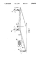
- FIG. 4 A spatial positioning and measurement system in accordance with a preferred embodiment of the invention is shown in FIG. 4.
- the reflector positioning system :
- the reflector positioning system includes a portable positioning reflector 200, shown in FIG. 2 and three or more fixed stations 101, shown in FIG. 1a.
- the portable positioning reflector 200 includes a 360° retroreflector unit 210 and a rod 220.
- the retroreflector unit preferably includes a plurality of retroreflectors arranged around the upper end thereof.
- the retroreflector unit 210 reflects light parallel to its incoming direction and produces a virtual image which is at it center.
- the rod 220 can be replaced by a tool or machine which is specifically suited for the positioning or measurement work being performed.
- the fixed stations 101 are located at known points in and/or around a measurement area, as shown in FIG. 4.
- the fixed station 101 generates a sets of rotating fanned laser beams 130. These fanned laser beams 130 periodically strike the P-reflector 200.
- the retroreflector unit 210 reflects the fanned laser beams 130 back toward the fixed station 101.
- the reflected light beam is received by a light sensitive detector 110 located on the fixed station 101.
- the light sensitive detector 110 generates an electrical pulse each time it receives a reflected light beam.
- the electrical pulses are sent to a processor 120 where they are individually time-labeled.
- the horizontal angle of the fanned laser beams as they strike the P-reflector 200 are determined at the processor by mathematical algorithms which use the timing information provided by the time-labels.
- time-labelling in a spatial positioning system, see U.S. application Ser. No. 07/570,268, the contents of which are incorporated herein by reference.
- the angle information is sent, via a communications link 145, to a central processing system 150.
- the central processing system 150 can determine the position of the P-reflector 200 if angle information is received from three or more fixed stations 101.
- the position of the P-reflector 200 is the intersection of the fanned laser beams from the three fixed stations as determined through plane equations:
- the communication link may be of any suitable type including, but not limited to, radio, optical fiber, microwave, and cable.
- the time-labels generated by the processor 120 at the fixed station 101, can be sent directly to the central processing system 150.
- the central processing system 150 would then perform all angle and position calculations necessary for determining the position of the P-reflector 200. Using this method the time references at the fixed stations would need to be synchronized.
- the electrical pulses generated by the light sensitive detector 110 of the fixed station 101, can be sent directly to the central processing system 150.
- the central processing system 150 would then perform the time-labeling of the electrical pulses and perform all angle and position calculations necessary for determining the position of the P-reflector 200.
- a portable positioning transponder (hereinafter referred to as "P-transponder") 300, shown in FIGS. 3 and 5, may be used in place of the P-reflector 200.
- the P-transponder 300 includes an optical light detector 330, a transponder 340, and a rod 320.
- the optical light detector 330 preferably has a view of 360° on the horizontal plane and a view less than +/-90° vertically.
- the optical light detector 330 senses changes in the magnitude of light energy (e.g. the presence of a fanned laser beam 130).
- a fixed station 102 as shown in FIG. 1b, is used in conjunction with P-transponder 300.
- the fixed station 102 is fitted with a transponder receiver 140 which is suited for receiving emissions from the P-transponder 300.
- the receiver 140 replaces the light sensitive detector 110 used in the P-reflector embodiment discussed above.
- an electrical pulse is generated and sent to the transponder 340.
- the receipt of the electrical pulse triggers the transponder 340 and causes an energy beam to be emitted.
- the energy beam may be of any suitable type, including electromagnetic energy in the visible or radio frequencies.
- the energy beam created by the transponder 340 is received by a transponder receiver 140.
- the receiver 140 creates an electrical pulse each time it receives an energy beam from the transponder 340.
- the electrical pulses are sent to the processor 120 where they are individually time-labeled.
- the horizontal angle of the fanned laser beams 130 as they strike the P-transponder 300 are determined at the processor 120 by mathematical algorithms which use the timing information provided by the time-labels. The time delay caused by electronics must be accounted for in calculations, if these delays are not constant.
- the horizontal angle information is sent, via a communications link 145, to a central processing system 150.
- the central processing system 150 can determine the position of the P-transponder 300 if angle information is received from three or more fixed stations 102.
- the position of the P-transponder is the intersection of the fanned laser beams from the three fixed stations 102 of this determined through plane equations as in the previous embodiment.
- the communication link 145 may be of any suitable type, including, but not limited to, radio, optical fiber, microwave, and cable.
- the time-labels generated by the processor 120 at the fixed station 102, can be sent directly to the central processing system 150.
- the central processing system 150 would then perform all angle and position calculations necessary for determining the position of the P-transponder 300. Using this method the time references at the fixed stations would need to be synchronized.
- the electrical pulses generated by the light sensitive detector 110 of the fixed station 102, can be sent directly to the central processing system 150.
- the central processing system 150 would perform the time-labeling of the electrical pulses and perform all angle and position calculations necessary for determining the position of the P-transponder 300.
- the energy beam emitted by the P-transponder 300 can be received by a transponder receiver 155 at the central processing system 150, as shown in FIG. 6.
- the transponder receiver 155 creates an electrical pulse each time it receives an energy beam.
- the electrical pulse is sent to the central processing system 150.
- the central processing system 150 performs the time-labeling of the electrical pulses and performs all angle and position calculations necessary for determining the position of the P-transponder 300.
- no receiving or signal processing capability is required in order to determine position information.
- Fixed station 103 has no receiving or signal processing capability at the fixed station, as shown in FIG. 1c.
- the central processing system 150 may include a monitor which continually outputs position information.
- the central processing system 150 may include a plotter or other printing device for outputting position information.
- the central processing system 150 may also include a control system for remote control of a vehicle or other device, attached to a portable position sensor, reflector, or transponder.
- the fixed stations 101 used in any of the above embodiments produce two or more sets of rotating fanned laser beams, only two fixed stations 101 are necessary to determine the location of any of the portable position sensors, reflectors, or transponders.
- fixed stations which have optical receiving and processing capabilities allows the position of the fixed stations to be determined in reference to each other.
- fixed stations can determine their position in reference to one another, fixed stations can be repositioned as long as two fixed stations remain stationary during repositioning of the other stations.
- the invention also includes an alternative fixed station 500, as shown in FIGS. 6 and 7.
- the lower optics 505 of each fixed station 500 produce a pair of fanned laser beams 510, 511, beam 510 being slanted from the axis of rotation 510 and beam 511 being parallel to the axis of rotation.
- the upper optics 506 of each fixed station produce fanned laser beam 512 which is parallel to the axis of rotation.
- any combination of fanned laser beams or sets of fanned laser beams and inclination of fanned laser beams can be used.
- the rotation of beams 510 511 is controlled by motor 502 while the rotation of beam 512 is controlled by motor 501.
- the two motors, 501 and 502 are rotated at different speeds.
- the fanned laser beams from the two motors, 510, 511, 512 can be differentiated via software phase-locked-loops (PLL's).
- PLL's software phase-locked-loops
- A angular velocity of motor 501
- motor 501 would spin once in the time motor 502 would spin twice.
- This equation defines a relationship between the two motors, 501 and 502.
- the direction in which each of the two motors, 501 and 502, spin is unimportant.
- Position of a portable position sensor can be determined whether the motors counter-rotate or rotate together in the same direction.
- a shutter 520 covers the angular field of view defined by the difference in total angular rotation during one rotation of the slower motor. Turning the laser off and then on again while the fanned laser beams 510, 511 and 512 are within the field of the shutter removes any ambiguity in identification of the beams. If the two motors, 501 and 502, are spinning at an integer multiple of one another, the size of the shutter 520 required is minimal. The shutter 520 needs only to be large enough to cover any hysteresis in the power supply to the laser. By monitoring the missing pulses, the processor can identify the laser beams 510, 511, and 512.
- each fixed station may produce a plurality of fan-shaped beams which oscillate back and forth instead of rotating. This oscillation may be achieved via any of a number of known mechanical, acousto-optical and other suitable mechanisms.
Abstract
Description
cos φ.sub.0,0 sin (θ.sub.0,0 -θ'.sub.0)(x-x.sub.0)-cos φ.sub.0,0 cos (θ.sub.0,0 -θ.sub.0)(y-y.sub.0)-sin φ.sub.0,0 (z-z.sub.0)=0
cos φ.sub.0,1 sin (θ.sub.0,1 -θ'.sub.0)(x-x.sub.0)-cos φ.sub.0,1 cos (θ.sub.0,1 -θ.sub.0)(y-y.sub.0)-sin φ.sub.0,1 (z-z.sub.0)=0
cos φ.sub.n,1 sin (θ.sub.n,1 -θ'.sub.0)(x-x.sub.0)-cos φ.sub.n,0 cos (θ.sub.n,0 -θ.sub.0)(y-y.sub.0)-sin φ.sub.n,0 (z-z.sub.0)=0
jA=kB
Claims (16)
Priority Applications (3)
| Application Number | Priority Date | Filing Date | Title |
|---|---|---|---|
| US07/755,780 US5294970A (en) | 1990-12-31 | 1991-09-06 | Spatial positioning system |
| US08/123,891 US5461473A (en) | 1990-12-31 | 1993-09-20 | Transmitter and receiver units for spatial position measurement system |
| US08/539,379 US5579102A (en) | 1991-06-17 | 1995-10-05 | Transmitter and receiver units for spatial position measurement system |
Applications Claiming Priority (2)
| Application Number | Priority Date | Filing Date | Title |
|---|---|---|---|
| US07/636,459 US5110202A (en) | 1990-08-17 | 1990-12-31 | Spatial positioning and measurement system |
| US07/755,780 US5294970A (en) | 1990-12-31 | 1991-09-06 | Spatial positioning system |
Related Parent Applications (1)
| Application Number | Title | Priority Date | Filing Date |
|---|---|---|---|
| US07/636,459 Continuation-In-Part US5110202A (en) | 1990-08-17 | 1990-12-31 | Spatial positioning and measurement system |
Related Child Applications (2)
| Application Number | Title | Priority Date | Filing Date |
|---|---|---|---|
| US08/123,891 Continuation-In-Part US5461473A (en) | 1990-12-31 | 1993-09-20 | Transmitter and receiver units for spatial position measurement system |
| US08/539,379 Continuation-In-Part US5579102A (en) | 1991-06-17 | 1995-10-05 | Transmitter and receiver units for spatial position measurement system |
Publications (1)
| Publication Number | Publication Date |
|---|---|
| US5294970A true US5294970A (en) | 1994-03-15 |
Family
ID=24552003
Family Applications (1)
| Application Number | Title | Priority Date | Filing Date |
|---|---|---|---|
| US07/755,780 Expired - Fee Related US5294970A (en) | 1990-12-31 | 1991-09-06 | Spatial positioning system |
Country Status (1)
| Country | Link |
|---|---|
| US (1) | US5294970A (en) |
Cited By (82)
| Publication number | Priority date | Publication date | Assignee | Title |
|---|---|---|---|---|
| US5422715A (en) * | 1993-03-11 | 1995-06-06 | Clarke; Thomas L. | Hybrid orthogonal localization and orientation system |
| US5587787A (en) * | 1992-06-22 | 1996-12-24 | J. Muller Ag | Process for measuring relative angles |
| DE19536295A1 (en) * | 1995-09-29 | 1997-04-03 | Daimler Benz Ag | Arrangement of partially structured flat signal markers for calibration and orientation of three=dimensional sensors |
| US5621531A (en) * | 1995-04-03 | 1997-04-15 | Laser Alignment, Inc. | Self-aligning sewer pipe laser |
| US5729475A (en) * | 1995-12-27 | 1998-03-17 | Romanik, Jr.; Carl J. | Optical system for accurate monitoring of the position and orientation of an object |
| US5742385A (en) * | 1996-07-16 | 1998-04-21 | The Boeing Company | Method of airplane interiors assembly using automated rotating laser technology |
| US5748353A (en) * | 1992-10-27 | 1998-05-05 | Topcon Corporation | Marking apparatus having feedback-controlled rotational laser beam |
| US5898490A (en) * | 1996-03-19 | 1999-04-27 | Kabushiki Kaisha Topcon | Laser survey instrument |
| US5982480A (en) * | 1997-05-08 | 1999-11-09 | Netmor Ltd. | Method for determining the position of targets in three dimensional space by optical chirped radio frequency modulation |
| US6133998A (en) * | 1997-08-01 | 2000-10-17 | Carl Zeiss Jena Gmbh | Method and device for target seeking for geodetic devices |
| US6198528B1 (en) * | 1998-05-22 | 2001-03-06 | Trimble Navigation Ltd | Laser-based three dimensional tracking system |
| EP1103824A2 (en) * | 1999-11-23 | 2001-05-30 | Xerox Corporation | Virtual control system using non-imaging scanners |
| WO2001069173A1 (en) * | 2000-03-10 | 2001-09-20 | Spectra Precision Inc. | Versatile transmitter and receiver for position measurement |
| EP1203930A2 (en) * | 2000-11-03 | 2002-05-08 | Nestle & Fischer GmbH & Co. KG | Method and device for aligning a light beam generated by a rotation laser |
| US6433866B1 (en) * | 1998-05-22 | 2002-08-13 | Trimble Navigation, Ltd | High precision GPS/RTK and laser machine control |
| US6452668B1 (en) | 1998-10-13 | 2002-09-17 | Arc Second, Inc. | Rotating head optical transmitter for position measurement system |
| US6459483B1 (en) * | 1998-02-10 | 2002-10-01 | Toolz, Ltd. | Level with angle and distance measurement apparatus |
| US6501543B2 (en) * | 2000-02-28 | 2002-12-31 | Arc Second, Inc. | Apparatus and method for determining position |
| US6519029B1 (en) * | 1999-03-22 | 2003-02-11 | Arc Second, Inc. | Low cost transmitter with calibration means for use in position measurement systems |
| US6545751B2 (en) * | 2000-02-28 | 2003-04-08 | Arc Second, Inc. | Low cost 2D position measurement system and method |
| US20030136901A1 (en) * | 2002-01-21 | 2003-07-24 | Fumio Ohtomo | Position determining apparatus and rotary laser apparatus used with the same |
| US6630993B1 (en) * | 1999-03-22 | 2003-10-07 | Arc Second Inc. | Method and optical receiver with easy setup means for use in position measurement systems |
| US20040135992A1 (en) * | 2002-11-26 | 2004-07-15 | Munro James F. | Apparatus for high accuracy distance and velocity measurement and methods thereof |
| US6799141B1 (en) | 1999-06-09 | 2004-09-28 | Beamcontrol Aps | Method for determining the channel gain between emitters and receivers |
| US20040223139A1 (en) * | 2003-05-09 | 2004-11-11 | Michael Vogel | Method for determining the spatial location and position of a reflector rod in relation to a marked ground point |
| US6947820B2 (en) | 2002-01-21 | 2005-09-20 | Kabushiki Kaisha Topcon | Construction machine control system |
| US20060224268A1 (en) * | 2005-03-31 | 2006-10-05 | The Boeing Company | Methods and systems for position sensing |
| US20070024845A1 (en) * | 2000-08-01 | 2007-02-01 | Androtec Gmbh | Measuring device and measuring method for determining distance and/or position |
| US20070198185A1 (en) * | 2002-12-11 | 2007-08-23 | Mcclure John A | GNSS control system and method |
| US20070265942A1 (en) * | 2006-04-21 | 2007-11-15 | The Boeing Company | Assembly task verification system and method |
| CN100359975C (en) * | 2004-09-23 | 2008-01-02 | 乐金电子(中国)研究开发中心有限公司 | Mobile communication terminal with wireless identification function and control method thereof |
| US20080077300A1 (en) * | 2006-09-26 | 2008-03-27 | Balogh Robert A | Method and apparatus for estimating landscape services |
| US20080154538A1 (en) * | 2006-10-21 | 2008-06-26 | Sam Stathis | System for accurately and precisely locating and marking a position in space using wireless communications and robotics |
| US20080167770A1 (en) * | 2007-01-05 | 2008-07-10 | Beeline Technologies Pty Ltd | Vehicle control system |
| US20080205494A1 (en) * | 2007-02-27 | 2008-08-28 | Whitehead Michael L | Unbiased code phase discriminator |
| US20090085815A1 (en) * | 2007-09-27 | 2009-04-02 | Jakab Andrew J | Tightly-coupled pcb gnss circuit and manufacturing method |
| US20090099730A1 (en) * | 2003-03-20 | 2009-04-16 | Mcclure John A | Satellite based vehicle guidance control in straight and contour modes |
| US20090121932A1 (en) * | 2003-03-20 | 2009-05-14 | Whitehead Michael L | Multi-antenna gnss positioning method and system |
| US20090164067A1 (en) * | 2003-03-20 | 2009-06-25 | Whitehead Michael L | Multiple-antenna gnss control system and method |
| US20090177435A1 (en) * | 2006-03-07 | 2009-07-09 | Mikko Heininen | Method, System and Computer Program Product for Locating a Measuring Device and for Measuring Large Objects |
| US20090204281A1 (en) * | 2008-02-10 | 2009-08-13 | Hemisphere Gps Llc | Visual, gnss and gyro autosteering control |
| US20090210083A1 (en) * | 2008-02-18 | 2009-08-20 | The Boeing Company | System and method for electronic inspection and record creation of assembly, repair and maintenance operations |
| US20090251366A1 (en) * | 2008-04-08 | 2009-10-08 | Mcclure John A | Gnss-based mobile communication system and method |
| US20100109944A1 (en) * | 2003-03-20 | 2010-05-06 | Whitehead Michael L | Gnss-based tracking of fixed or slow-moving structures |
| US20100161179A1 (en) * | 2008-12-22 | 2010-06-24 | Mcclure John A | Integrated dead reckoning and gnss/ins positioning |
| US20100176991A1 (en) * | 2008-12-11 | 2010-07-15 | Webber Mark R | Gnss superband asic with simultaneous multi-frequency down conversion |
| US20100292954A1 (en) * | 2009-05-13 | 2010-11-18 | Chih-Hsiung Lin | Method and device for detecting rotating angle of reflector |
| US20100312428A1 (en) * | 2003-03-20 | 2010-12-09 | Roberge Andre C | Gnss guidance and machine control |
| US20110015817A1 (en) * | 2009-07-17 | 2011-01-20 | Reeve David R | Optical tracking vehicle control system and method |
| US20110018765A1 (en) * | 2007-10-08 | 2011-01-27 | Whitehead Michael L | Gnss receiver and external storage device system and gnss data processing method |
| US20110022238A1 (en) * | 2009-07-22 | 2011-01-27 | Pollock Colin J | Gnss control system and method for irrigation and related applications |
| US20110054729A1 (en) * | 2004-03-19 | 2011-03-03 | Whitehead Michael L | Multi-antenna gnss control system and method |
| US20110057834A1 (en) * | 2009-09-04 | 2011-03-10 | Miller Steven R | Multi-frequency gnss receiver baseband dsp |
| US20110172887A1 (en) * | 2009-11-30 | 2011-07-14 | Reeve David R | Vehicle assembly control method for collaborative behavior |
| US20110196565A1 (en) * | 2010-02-09 | 2011-08-11 | Collins Dennis M | Gnss contour guidance path selection |
| US8085196B2 (en) | 2009-03-11 | 2011-12-27 | Hemisphere Gps Llc | Removing biases in dual frequency GNSS receivers using SBAS |
| US8087176B1 (en) | 2010-06-28 | 2012-01-03 | Trimble Navigation Ltd | Two dimension layout and point transfer system |
| US8174437B2 (en) | 2009-07-29 | 2012-05-08 | Hemisphere Gps Llc | System and method for augmenting DGNSS with internally-generated differential correction |
| US20120198711A1 (en) * | 2010-06-28 | 2012-08-09 | Trimble Navigation Limited | Three dimensional layout and point transfer system |
| US8265826B2 (en) | 2003-03-20 | 2012-09-11 | Hemisphere GPS, LLC | Combined GNSS gyroscope control system and method |
| US8271194B2 (en) | 2004-03-19 | 2012-09-18 | Hemisphere Gps Llc | Method and system using GNSS phase measurements for relative positioning |
| US8386129B2 (en) | 2009-01-17 | 2013-02-26 | Hemipshere GPS, LLC | Raster-based contour swathing for guidance and variable-rate chemical application |
| US8548649B2 (en) | 2009-10-19 | 2013-10-01 | Agjunction Llc | GNSS optimized aircraft control system and method |
| US20130298413A1 (en) * | 2010-11-10 | 2013-11-14 | Leica Geosystems Ag | Construction laser system comprising a rotation laser and a laser receiver, and method |
| US8649930B2 (en) | 2009-09-17 | 2014-02-11 | Agjunction Llc | GNSS integrated multi-sensor control system and method |
| US8943701B2 (en) | 2010-06-28 | 2015-02-03 | Trimble Navigation Limited | Automated layout and point transfer system |
| US20150052765A1 (en) * | 2013-08-23 | 2015-02-26 | Kabushiki Kaisha Topcon | Surveying instrument and surveying operation system |
| US20150052766A1 (en) * | 2013-08-23 | 2015-02-26 | Kabushiki Kaisha Topcon | Surveying instrument |
| WO2015066992A1 (en) * | 2013-11-07 | 2015-05-14 | 天津大学 | Top-mounted up-side-down transmit base station for intersection measurement of angle |
| US20150346319A1 (en) * | 2012-12-20 | 2015-12-03 | Hilti Aktiengesellschaft | Method and Device for Determining the Position Coordinates of a Target Object |
| CN107144848A (en) * | 2017-03-31 | 2017-09-08 | 成都理想境界科技有限公司 | A kind of locating base station and alignment system |
| US9880022B1 (en) | 2016-11-14 | 2018-01-30 | Trimble Navigation Limited | Point layout system with third transmitter |
| US9880562B2 (en) | 2003-03-20 | 2018-01-30 | Agjunction Llc | GNSS and optical guidance and machine control |
| USRE47101E1 (en) | 2003-03-20 | 2018-10-30 | Agjunction Llc | Control for dispensing material from vehicle |
| US10338186B2 (en) * | 2014-11-10 | 2019-07-02 | Valve Corporation | Positional tracking systems and methods |
| US10690498B2 (en) | 2017-05-10 | 2020-06-23 | Trimble, Inc. | Automatic point layout and staking system |
| US10859702B1 (en) * | 2017-12-21 | 2020-12-08 | Facebook Technologies, Llc | Positional tracking using retroreflectors |
| USRE48527E1 (en) | 2007-01-05 | 2021-04-20 | Agjunction Llc | Optical tracking vehicle control system and method |
| US11226199B2 (en) | 2017-01-17 | 2022-01-18 | Trimble Navigation Limited | Point layout system using single laser transmitter |
| US11280607B2 (en) * | 2016-03-08 | 2022-03-22 | Staff Holdings Pty Ltd | Laser level checking |
| US11435445B2 (en) | 2019-12-20 | 2022-09-06 | Trimble, Inc. | Laser receiver and target with lighted indicators |
| US11435182B2 (en) | 2019-12-20 | 2022-09-06 | Trimble, Inc. | Laser receiver and target with lighted indicators |
Citations (6)
| Publication number | Priority date | Publication date | Assignee | Title |
|---|---|---|---|---|
| US4700301A (en) * | 1983-11-02 | 1987-10-13 | Dyke Howard L | Method of automatically steering agricultural type vehicles |
| US4709580A (en) * | 1986-02-26 | 1987-12-01 | Bd Systems, Inc. | Retroflective attitude determining system |
| US4791297A (en) * | 1987-03-26 | 1988-12-13 | Barnes Engineering Company | Yaw sensing conical scanner horizon sensor |
| US4820041A (en) * | 1986-11-12 | 1989-04-11 | Agtek Development Co., Inc. | Position sensing system for surveying and grading |
| US4830489A (en) * | 1986-08-20 | 1989-05-16 | Spectra-Physics, Inc. | Three dimensional laser beam survey system |
| US4895440A (en) * | 1988-08-22 | 1990-01-23 | Spectra-Physics, Inc. | Laser-based measurement system |
-
1991
- 1991-09-06 US US07/755,780 patent/US5294970A/en not_active Expired - Fee Related
Patent Citations (6)
| Publication number | Priority date | Publication date | Assignee | Title |
|---|---|---|---|---|
| US4700301A (en) * | 1983-11-02 | 1987-10-13 | Dyke Howard L | Method of automatically steering agricultural type vehicles |
| US4709580A (en) * | 1986-02-26 | 1987-12-01 | Bd Systems, Inc. | Retroflective attitude determining system |
| US4830489A (en) * | 1986-08-20 | 1989-05-16 | Spectra-Physics, Inc. | Three dimensional laser beam survey system |
| US4820041A (en) * | 1986-11-12 | 1989-04-11 | Agtek Development Co., Inc. | Position sensing system for surveying and grading |
| US4791297A (en) * | 1987-03-26 | 1988-12-13 | Barnes Engineering Company | Yaw sensing conical scanner horizon sensor |
| US4895440A (en) * | 1988-08-22 | 1990-01-23 | Spectra-Physics, Inc. | Laser-based measurement system |
Cited By (150)
| Publication number | Priority date | Publication date | Assignee | Title |
|---|---|---|---|---|
| US5587787A (en) * | 1992-06-22 | 1996-12-24 | J. Muller Ag | Process for measuring relative angles |
| US5926305A (en) * | 1992-10-27 | 1999-07-20 | Topcon Corporation | Marking apparatus having feedback-controlled rotational laser beam |
| US5748353A (en) * | 1992-10-27 | 1998-05-05 | Topcon Corporation | Marking apparatus having feedback-controlled rotational laser beam |
| US5751459A (en) * | 1992-10-27 | 1998-05-12 | Topcon Corporation | Marking apparatus having feedback-controlled rotational laser beam |
| US5422715A (en) * | 1993-03-11 | 1995-06-06 | Clarke; Thomas L. | Hybrid orthogonal localization and orientation system |
| US5621531A (en) * | 1995-04-03 | 1997-04-15 | Laser Alignment, Inc. | Self-aligning sewer pipe laser |
| DE19536295A1 (en) * | 1995-09-29 | 1997-04-03 | Daimler Benz Ag | Arrangement of partially structured flat signal markers for calibration and orientation of three=dimensional sensors |
| DE19536295C2 (en) * | 1995-09-29 | 2000-12-14 | Daimler Chrysler Ag | Spatially designed signal mark |
| US5729475A (en) * | 1995-12-27 | 1998-03-17 | Romanik, Jr.; Carl J. | Optical system for accurate monitoring of the position and orientation of an object |
| US5884239A (en) * | 1995-12-27 | 1999-03-16 | Romanik, Jr.; Carl J. | Optical system for accurate monitoring of the position and orientation of an object |
| US5898490A (en) * | 1996-03-19 | 1999-04-27 | Kabushiki Kaisha Topcon | Laser survey instrument |
| US5742385A (en) * | 1996-07-16 | 1998-04-21 | The Boeing Company | Method of airplane interiors assembly using automated rotating laser technology |
| US5982480A (en) * | 1997-05-08 | 1999-11-09 | Netmor Ltd. | Method for determining the position of targets in three dimensional space by optical chirped radio frequency modulation |
| US6133998A (en) * | 1997-08-01 | 2000-10-17 | Carl Zeiss Jena Gmbh | Method and device for target seeking for geodetic devices |
| US6741343B2 (en) | 1998-02-10 | 2004-05-25 | Toolz, Ltd. | Level with angle and distance measurement apparatus |
| US6459483B1 (en) * | 1998-02-10 | 2002-10-01 | Toolz, Ltd. | Level with angle and distance measurement apparatus |
| US6198528B1 (en) * | 1998-05-22 | 2001-03-06 | Trimble Navigation Ltd | Laser-based three dimensional tracking system |
| US6400452B1 (en) * | 1998-05-22 | 2002-06-04 | Trimble Navigation, Ltd | Three dimensional laser control and tracking system |
| US6433866B1 (en) * | 1998-05-22 | 2002-08-13 | Trimble Navigation, Ltd | High precision GPS/RTK and laser machine control |
| US6452668B1 (en) | 1998-10-13 | 2002-09-17 | Arc Second, Inc. | Rotating head optical transmitter for position measurement system |
| US6621565B2 (en) * | 1998-10-13 | 2003-09-16 | Arc Second Inc. | Rotating head optical transmitter for position measurement system |
| US6519029B1 (en) * | 1999-03-22 | 2003-02-11 | Arc Second, Inc. | Low cost transmitter with calibration means for use in position measurement systems |
| US6618133B2 (en) * | 1999-03-22 | 2003-09-09 | Arc Second, Inc. | Low cost transmitter with calibration means for use in position measurement systems |
| US6630993B1 (en) * | 1999-03-22 | 2003-10-07 | Arc Second Inc. | Method and optical receiver with easy setup means for use in position measurement systems |
| US6799141B1 (en) | 1999-06-09 | 2004-09-28 | Beamcontrol Aps | Method for determining the channel gain between emitters and receivers |
| EP1103824A2 (en) * | 1999-11-23 | 2001-05-30 | Xerox Corporation | Virtual control system using non-imaging scanners |
| EP1103824A3 (en) * | 1999-11-23 | 2002-08-28 | Xerox Corporation | Virtual control system using non-imaging scanners |
| US6545751B2 (en) * | 2000-02-28 | 2003-04-08 | Arc Second, Inc. | Low cost 2D position measurement system and method |
| US6501543B2 (en) * | 2000-02-28 | 2002-12-31 | Arc Second, Inc. | Apparatus and method for determining position |
| WO2001069173A1 (en) * | 2000-03-10 | 2001-09-20 | Spectra Precision Inc. | Versatile transmitter and receiver for position measurement |
| US6643004B2 (en) * | 2000-03-10 | 2003-11-04 | Trimble Navigation Limited | Versatile transmitter and receiver for position measurement |
| US20040008338A1 (en) * | 2000-03-10 | 2004-01-15 | Detweiler Philip L. | Versatile transmitter and receiver for position measurement |
| US20050122507A1 (en) * | 2000-03-10 | 2005-06-09 | Detweiler Philip L. | Versatile transmitter and receiver for position measurement |
| US7064819B2 (en) | 2000-03-10 | 2006-06-20 | Trimble Navigation Limited | Versatile transmitter and receiver for position measurement |
| US6870608B2 (en) | 2000-03-10 | 2005-03-22 | Trimble Navigation Limited | Versatile transmitter and receiver for position measurement |
| US7394527B2 (en) * | 2000-08-01 | 2008-07-01 | Androtec Gmbh | Measuring device and measuring method for determining distance and/or position |
| US20070024845A1 (en) * | 2000-08-01 | 2007-02-01 | Androtec Gmbh | Measuring device and measuring method for determining distance and/or position |
| EP1203930A2 (en) * | 2000-11-03 | 2002-05-08 | Nestle & Fischer GmbH & Co. KG | Method and device for aligning a light beam generated by a rotation laser |
| EP1203930A3 (en) * | 2000-11-03 | 2002-07-31 | Nestle & Fischer GmbH & Co. KG | Method and device for aligning a light beam generated by a rotation laser |
| US7022962B2 (en) | 2002-01-21 | 2006-04-04 | Kabushiki Kaisha Topcon | Position determining apparatus |
| US20030136901A1 (en) * | 2002-01-21 | 2003-07-24 | Fumio Ohtomo | Position determining apparatus and rotary laser apparatus used with the same |
| US6947820B2 (en) | 2002-01-21 | 2005-09-20 | Kabushiki Kaisha Topcon | Construction machine control system |
| US20080100822A1 (en) * | 2002-11-26 | 2008-05-01 | Munro James F | Apparatus for high accuracy distance and velocity measurement and methods thereof |
| WO2005008271A2 (en) * | 2002-11-26 | 2005-01-27 | Munro James F | An apparatus for high accuracy distance and velocity measurement and methods thereof |
| WO2005008271A3 (en) * | 2002-11-26 | 2009-06-18 | James F Munro | An apparatus for high accuracy distance and velocity measurement and methods thereof |
| US7202941B2 (en) * | 2002-11-26 | 2007-04-10 | Munro James F | Apparatus for high accuracy distance and velocity measurement and methods thereof |
| US20040135992A1 (en) * | 2002-11-26 | 2004-07-15 | Munro James F. | Apparatus for high accuracy distance and velocity measurement and methods thereof |
| US7885745B2 (en) | 2002-12-11 | 2011-02-08 | Hemisphere Gps Llc | GNSS control system and method |
| US20070198185A1 (en) * | 2002-12-11 | 2007-08-23 | Mcclure John A | GNSS control system and method |
| US20090121932A1 (en) * | 2003-03-20 | 2009-05-14 | Whitehead Michael L | Multi-antenna gnss positioning method and system |
| US8594879B2 (en) | 2003-03-20 | 2013-11-26 | Agjunction Llc | GNSS guidance and machine control |
| US8138970B2 (en) | 2003-03-20 | 2012-03-20 | Hemisphere Gps Llc | GNSS-based tracking of fixed or slow-moving structures |
| US8190337B2 (en) | 2003-03-20 | 2012-05-29 | Hemisphere GPS, LLC | Satellite based vehicle guidance control in straight and contour modes |
| US8140223B2 (en) | 2003-03-20 | 2012-03-20 | Hemisphere Gps Llc | Multiple-antenna GNSS control system and method |
| US8265826B2 (en) | 2003-03-20 | 2012-09-11 | Hemisphere GPS, LLC | Combined GNSS gyroscope control system and method |
| US20100312428A1 (en) * | 2003-03-20 | 2010-12-09 | Roberge Andre C | Gnss guidance and machine control |
| US10168714B2 (en) | 2003-03-20 | 2019-01-01 | Agjunction Llc | GNSS and optical guidance and machine control |
| USRE47101E1 (en) | 2003-03-20 | 2018-10-30 | Agjunction Llc | Control for dispensing material from vehicle |
| US8686900B2 (en) | 2003-03-20 | 2014-04-01 | Hemisphere GNSS, Inc. | Multi-antenna GNSS positioning method and system |
| US20100109944A1 (en) * | 2003-03-20 | 2010-05-06 | Whitehead Michael L | Gnss-based tracking of fixed or slow-moving structures |
| US9886038B2 (en) | 2003-03-20 | 2018-02-06 | Agjunction Llc | GNSS and optical guidance and machine control |
| US20090099730A1 (en) * | 2003-03-20 | 2009-04-16 | Mcclure John A | Satellite based vehicle guidance control in straight and contour modes |
| US9880562B2 (en) | 2003-03-20 | 2018-01-30 | Agjunction Llc | GNSS and optical guidance and machine control |
| US20090164067A1 (en) * | 2003-03-20 | 2009-06-25 | Whitehead Michael L | Multiple-antenna gnss control system and method |
| US7079234B2 (en) * | 2003-05-09 | 2006-07-18 | Trimble Jena Gmbh | Method for determining the spatial location and position of a reflector rod in relation to a marked ground point |
| US20040223139A1 (en) * | 2003-05-09 | 2004-11-11 | Michael Vogel | Method for determining the spatial location and position of a reflector rod in relation to a marked ground point |
| DE10321749B4 (en) | 2003-05-09 | 2018-05-30 | Trimble Jena Gmbh | Method and arrangement for determining the spatial position and position of a reflector rod in relation to a stopping point |
| US20110054729A1 (en) * | 2004-03-19 | 2011-03-03 | Whitehead Michael L | Multi-antenna gnss control system and method |
| US8271194B2 (en) | 2004-03-19 | 2012-09-18 | Hemisphere Gps Llc | Method and system using GNSS phase measurements for relative positioning |
| US8583315B2 (en) | 2004-03-19 | 2013-11-12 | Agjunction Llc | Multi-antenna GNSS control system and method |
| CN100359975C (en) * | 2004-09-23 | 2008-01-02 | 乐金电子(中国)研究开发中心有限公司 | Mobile communication terminal with wireless identification function and control method thereof |
| US7305277B2 (en) | 2005-03-31 | 2007-12-04 | The Boeing Company | Methods and systems for position sensing of components in a manufacturing operation |
| US7774083B2 (en) | 2005-03-31 | 2010-08-10 | The Boeing Company | Methods and systems for position sensing |
| US20080046109A1 (en) * | 2005-03-31 | 2008-02-21 | The Boeing Company | Methods and Systems for Position Sensing |
| US20060224268A1 (en) * | 2005-03-31 | 2006-10-05 | The Boeing Company | Methods and systems for position sensing |
| US20090177435A1 (en) * | 2006-03-07 | 2009-07-09 | Mikko Heininen | Method, System and Computer Program Product for Locating a Measuring Device and for Measuring Large Objects |
| US8938315B2 (en) | 2006-04-21 | 2015-01-20 | The Boeing Company | Assembly task verification method |
| US20070265942A1 (en) * | 2006-04-21 | 2007-11-15 | The Boeing Company | Assembly task verification system and method |
| US8630729B2 (en) | 2006-04-21 | 2014-01-14 | The Boeing Company | Assembly task verification system and method |
| US8200354B2 (en) | 2006-04-21 | 2012-06-12 | The Boeing Company | Assembly task verification system and method |
| US20080077300A1 (en) * | 2006-09-26 | 2008-03-27 | Balogh Robert A | Method and apparatus for estimating landscape services |
| US9747698B2 (en) | 2006-10-21 | 2017-08-29 | Sam Stathis | System for accurately and precisely locating and marking a position in space using wireless communications and robotics |
| US20080154538A1 (en) * | 2006-10-21 | 2008-06-26 | Sam Stathis | System for accurately and precisely locating and marking a position in space using wireless communications and robotics |
| WO2008067349A3 (en) * | 2006-10-21 | 2008-08-28 | Sam Stathis | System for accurately and precisely locating and marking a position in space using wireless communications and robotics |
| US7835832B2 (en) | 2007-01-05 | 2010-11-16 | Hemisphere Gps Llc | Vehicle control system |
| US20080167770A1 (en) * | 2007-01-05 | 2008-07-10 | Beeline Technologies Pty Ltd | Vehicle control system |
| WO2008080193A1 (en) * | 2007-01-05 | 2008-07-10 | Hemisphere Gps Llc | A vehicle control system |
| USRE48527E1 (en) | 2007-01-05 | 2021-04-20 | Agjunction Llc | Optical tracking vehicle control system and method |
| US20110118938A1 (en) * | 2007-01-05 | 2011-05-19 | Andrew John Macdonald | Vehicle control system |
| US8000381B2 (en) | 2007-02-27 | 2011-08-16 | Hemisphere Gps Llc | Unbiased code phase discriminator |
| US20080205494A1 (en) * | 2007-02-27 | 2008-08-28 | Whitehead Michael L | Unbiased code phase discriminator |
| US7948769B2 (en) | 2007-09-27 | 2011-05-24 | Hemisphere Gps Llc | Tightly-coupled PCB GNSS circuit and manufacturing method |
| US20090085815A1 (en) * | 2007-09-27 | 2009-04-02 | Jakab Andrew J | Tightly-coupled pcb gnss circuit and manufacturing method |
| US20110018765A1 (en) * | 2007-10-08 | 2011-01-27 | Whitehead Michael L | Gnss receiver and external storage device system and gnss data processing method |
| US8456356B2 (en) | 2007-10-08 | 2013-06-04 | Hemisphere Gnss Inc. | GNSS receiver and external storage device system and GNSS data processing method |
| US20090204281A1 (en) * | 2008-02-10 | 2009-08-13 | Hemisphere Gps Llc | Visual, gnss and gyro autosteering control |
| US9002566B2 (en) | 2008-02-10 | 2015-04-07 | AgJunction, LLC | Visual, GNSS and gyro autosteering control |
| US8630819B2 (en) | 2008-02-18 | 2014-01-14 | The Boeing Company | System and method for electronic inspection and record creation of assembly, repair and maintenance operations |
| US20090210083A1 (en) * | 2008-02-18 | 2009-08-20 | The Boeing Company | System and method for electronic inspection and record creation of assembly, repair and maintenance operations |
| US20090251366A1 (en) * | 2008-04-08 | 2009-10-08 | Mcclure John A | Gnss-based mobile communication system and method |
| US8018376B2 (en) | 2008-04-08 | 2011-09-13 | Hemisphere Gps Llc | GNSS-based mobile communication system and method |
| US8217833B2 (en) | 2008-12-11 | 2012-07-10 | Hemisphere Gps Llc | GNSS superband ASIC with simultaneous multi-frequency down conversion |
| US20100176991A1 (en) * | 2008-12-11 | 2010-07-15 | Webber Mark R | Gnss superband asic with simultaneous multi-frequency down conversion |
| US20100161179A1 (en) * | 2008-12-22 | 2010-06-24 | Mcclure John A | Integrated dead reckoning and gnss/ins positioning |
| US8386129B2 (en) | 2009-01-17 | 2013-02-26 | Hemipshere GPS, LLC | Raster-based contour swathing for guidance and variable-rate chemical application |
| USRE48509E1 (en) | 2009-01-17 | 2021-04-13 | Agjunction Llc | Raster-based contour swathing for guidance and variable-rate chemical application |
| USRE47055E1 (en) | 2009-01-17 | 2018-09-25 | Agjunction Llc | Raster-based contour swathing for guidance and variable-rate chemical application |
| US8085196B2 (en) | 2009-03-11 | 2011-12-27 | Hemisphere Gps Llc | Removing biases in dual frequency GNSS receivers using SBAS |
| US20100292954A1 (en) * | 2009-05-13 | 2010-11-18 | Chih-Hsiung Lin | Method and device for detecting rotating angle of reflector |
| US8311696B2 (en) | 2009-07-17 | 2012-11-13 | Hemisphere Gps Llc | Optical tracking vehicle control system and method |
| US20110015817A1 (en) * | 2009-07-17 | 2011-01-20 | Reeve David R | Optical tracking vehicle control system and method |
| US8401704B2 (en) | 2009-07-22 | 2013-03-19 | Hemisphere GPS, LLC | GNSS control system and method for irrigation and related applications |
| US20110022238A1 (en) * | 2009-07-22 | 2011-01-27 | Pollock Colin J | Gnss control system and method for irrigation and related applications |
| US8174437B2 (en) | 2009-07-29 | 2012-05-08 | Hemisphere Gps Llc | System and method for augmenting DGNSS with internally-generated differential correction |
| US8334804B2 (en) | 2009-09-04 | 2012-12-18 | Hemisphere Gps Llc | Multi-frequency GNSS receiver baseband DSP |
| US20110057834A1 (en) * | 2009-09-04 | 2011-03-10 | Miller Steven R | Multi-frequency gnss receiver baseband dsp |
| US8649930B2 (en) | 2009-09-17 | 2014-02-11 | Agjunction Llc | GNSS integrated multi-sensor control system and method |
| USRE47648E1 (en) | 2009-09-17 | 2019-10-15 | Agjunction Llc | Integrated multi-sensor control system and method |
| US8548649B2 (en) | 2009-10-19 | 2013-10-01 | Agjunction Llc | GNSS optimized aircraft control system and method |
| US20110172887A1 (en) * | 2009-11-30 | 2011-07-14 | Reeve David R | Vehicle assembly control method for collaborative behavior |
| US20110196565A1 (en) * | 2010-02-09 | 2011-08-11 | Collins Dennis M | Gnss contour guidance path selection |
| US8583326B2 (en) | 2010-02-09 | 2013-11-12 | Agjunction Llc | GNSS contour guidance path selection |
| US8087176B1 (en) | 2010-06-28 | 2012-01-03 | Trimble Navigation Ltd | Two dimension layout and point transfer system |
| US10935369B2 (en) * | 2010-06-28 | 2021-03-02 | Trimble Navigation Limited | Automated layout and point transfer system |
| US10145676B2 (en) | 2010-06-28 | 2018-12-04 | Trimble Navigation Limited | Automated layout and point transfer system |
| US8943701B2 (en) | 2010-06-28 | 2015-02-03 | Trimble Navigation Limited | Automated layout and point transfer system |
| US8745884B2 (en) * | 2010-06-28 | 2014-06-10 | Trimble Navigation Limited | Three dimensional layout and point transfer system |
| US20120198711A1 (en) * | 2010-06-28 | 2012-08-09 | Trimble Navigation Limited | Three dimensional layout and point transfer system |
| US8595946B2 (en) | 2010-06-28 | 2013-12-03 | Trimble Navigation Limited | Two dimension layout and point transfer system |
| US8281495B2 (en) | 2010-06-28 | 2012-10-09 | Trimble Navigation Limited | Two dimension layout and point transfer system |
| US9207077B2 (en) * | 2010-11-10 | 2015-12-08 | Leica Geosystems Ag | Construction laser system comprising a rotation laser and a laser receiver, and method |
| US20130298413A1 (en) * | 2010-11-10 | 2013-11-14 | Leica Geosystems Ag | Construction laser system comprising a rotation laser and a laser receiver, and method |
| US20150346319A1 (en) * | 2012-12-20 | 2015-12-03 | Hilti Aktiengesellschaft | Method and Device for Determining the Position Coordinates of a Target Object |
| US20150052765A1 (en) * | 2013-08-23 | 2015-02-26 | Kabushiki Kaisha Topcon | Surveying instrument and surveying operation system |
| US9523574B2 (en) * | 2013-08-23 | 2016-12-20 | Kabushiki Kaisha Topcon | Surveying instrument |
| US9482532B2 (en) * | 2013-08-23 | 2016-11-01 | Kabushiki Kaisha Topcon | Surveying instrument and surveying operation system |
| JP2015040831A (en) * | 2013-08-23 | 2015-03-02 | 株式会社トプコン | Surveying instrument, and surveying work system |
| JP2015040830A (en) * | 2013-08-23 | 2015-03-02 | 株式会社トプコン | Surveying instrument |
| US20150052766A1 (en) * | 2013-08-23 | 2015-02-26 | Kabushiki Kaisha Topcon | Surveying instrument |
| WO2015066992A1 (en) * | 2013-11-07 | 2015-05-14 | 天津大学 | Top-mounted up-side-down transmit base station for intersection measurement of angle |
| US10338186B2 (en) * | 2014-11-10 | 2019-07-02 | Valve Corporation | Positional tracking systems and methods |
| US11280607B2 (en) * | 2016-03-08 | 2022-03-22 | Staff Holdings Pty Ltd | Laser level checking |
| US9880022B1 (en) | 2016-11-14 | 2018-01-30 | Trimble Navigation Limited | Point layout system with third transmitter |
| US11226199B2 (en) | 2017-01-17 | 2022-01-18 | Trimble Navigation Limited | Point layout system using single laser transmitter |
| US11802764B2 (en) | 2017-01-17 | 2023-10-31 | Trimble Navigation Limited | Point layout system using single laser transmitter |
| CN107144848A (en) * | 2017-03-31 | 2017-09-08 | 成都理想境界科技有限公司 | A kind of locating base station and alignment system |
| US10690498B2 (en) | 2017-05-10 | 2020-06-23 | Trimble, Inc. | Automatic point layout and staking system |
| US10859702B1 (en) * | 2017-12-21 | 2020-12-08 | Facebook Technologies, Llc | Positional tracking using retroreflectors |
| US11435445B2 (en) | 2019-12-20 | 2022-09-06 | Trimble, Inc. | Laser receiver and target with lighted indicators |
| US11435182B2 (en) | 2019-12-20 | 2022-09-06 | Trimble, Inc. | Laser receiver and target with lighted indicators |
Similar Documents
| Publication | Publication Date | Title |
|---|---|---|
| US5294970A (en) | Spatial positioning system | |
| US5110202A (en) | Spatial positioning and measurement system | |
| EP0543954B1 (en) | Spatial positioning system | |
| US10365352B2 (en) | Distance measurement instrument with scanning function | |
| EP0659265B1 (en) | Spatial positioning system | |
| US7474256B2 (en) | Position detecting system, and transmitting and receiving apparatuses for the position detecting system | |
| EP0358368B1 (en) | Laser based measurement system | |
| US20130202010A1 (en) | Target apparatus and method | |
| CN101750012A (en) | Device for measuring six-dimensional position poses of object | |
| JP7357124B2 (en) | Targets, survey methods and programs | |
| US20150022826A1 (en) | Target apparatus and method | |
| CN210572728U (en) | Laser radar and laser radar system | |
| CN212008926U (en) | Laser radar | |
| US10073165B2 (en) | Distance measurement instrument with scanning function | |
| EP0201598B1 (en) | Laser position measurement and alignment | |
| US4307939A (en) | Oscillating retroreflector | |
| JP2689266B2 (en) | Three-dimensional position measuring device | |
| JPH06167339A (en) | Surveying device | |
| JPH03251706A (en) | Method and apparatus for detecting three-dimensional position | |
| JPH06174466A (en) | Surveying device | |
| JPH06307869A (en) | Method for measuring displacement of sheet pile | |
| JP2000182165A (en) | Monitoring system | |
| JPH0743156A (en) | Survey device | |
| JPH06174469A (en) | Marking device | |
| JPH0157312B2 (en) |
Legal Events
| Date | Code | Title | Description |
|---|---|---|---|
| AS | Assignment |
Owner name: SPATIAL POSITIONING SYSTEMS, INC.,, VIRGINIA Free format text: ASSIGNMENT OF ASSIGNORS INTEREST.;ASSIGNORS:DORNBUSCH, ANDREW W.;LUNDBERG, ERIC J.;BELIVEAU, YVAN J.;AND OTHERS;REEL/FRAME:005849/0421;SIGNING DATES FROM 19910904 TO 19910905 |
|
| REMI | Maintenance fee reminder mailed | ||
| FPAY | Fee payment |
Year of fee payment: 4 |
|
| SULP | Surcharge for late payment | ||
| FP | Lapsed due to failure to pay maintenance fee |
Effective date: 19980318 |
|
| AS | Assignment |
Owner name: ARC SECOND, INC., VIRGINIA Free format text: CHANGE OF NAME;ASSIGNOR:SPATIAL POSITIONING SYSTEMS, INC.;REEL/FRAME:009547/0941 Effective date: 19980309 |
|
| AS | Assignment |
Owner name: PNC BANK, NATIONAL ASSOCIATION, PENNSYLVANIA Free format text: SECURITY AGREEMENT;ASSIGNOR:ARC SECOND, INC.;REEL/FRAME:010371/0167 Effective date: 19991001 |
|
| AS | Assignment |
Owner name: IMPERIAL BANK, CALIFORNIA Free format text: SECURITY INTEREST;ASSIGNOR:ARC SECOND, INC.;REEL/FRAME:011190/0537 Effective date: 20000615 |
|
| AS | Assignment |
Owner name: ARC SECOND, INC., VIRGINIA Free format text: RELEASE OF SECURITY INTEREST;ASSIGNOR:IMPERIAL BANK;REEL/FRAME:012014/0852 Effective date: 20010712 |
|
| AS | Assignment |
Owner name: SOFINOV, SOCIETE FINANCIERE D'INNOVATION INC., CAN Free format text: SECURITY INTEREST;ASSIGNOR:ARC SECOND, INC.;REEL/FRAME:012166/0072 Effective date: 20010709 |
|
| REMI | Maintenance fee reminder mailed | ||
| LAPS | Lapse for failure to pay maintenance fees | ||
| STCH | Information on status: patent discontinuation |
Free format text: PATENT EXPIRED DUE TO NONPAYMENT OF MAINTENANCE FEES UNDER 37 CFR 1.362 |
|
| FP | Lapsed due to failure to pay maintenance fee |
Effective date: 20020315 |