US5300260A - Fog generator - Google Patents
Fog generator Download PDFInfo
- Publication number
- US5300260A US5300260A US08/049,381 US4938193A US5300260A US 5300260 A US5300260 A US 5300260A US 4938193 A US4938193 A US 4938193A US 5300260 A US5300260 A US 5300260A
- Authority
- US
- United States
- Prior art keywords
- reservoir
- gas
- liquid
- fog generator
- ultrasonic transducers
- Prior art date
- Legal status (The legal status is an assumption and is not a legal conclusion. Google has not performed a legal analysis and makes no representation as to the accuracy of the status listed.)
- Expired - Fee Related
Links
- 239000007788 liquid Substances 0.000 claims abstract description 49
- 238000005192 partition Methods 0.000 claims description 11
- 230000015572 biosynthetic process Effects 0.000 claims description 5
- 230000004888 barrier function Effects 0.000 claims description 3
- 239000007789 gas Substances 0.000 description 16
- 241000196324 Embryophyta Species 0.000 description 9
- XLYOFNOQVPJJNP-UHFFFAOYSA-N water Substances O XLYOFNOQVPJJNP-UHFFFAOYSA-N 0.000 description 9
- 238000003898 horticulture Methods 0.000 description 3
- 239000002245 particle Substances 0.000 description 3
- IJGRMHOSHXDMSA-UHFFFAOYSA-N Atomic nitrogen Chemical compound N#N IJGRMHOSHXDMSA-UHFFFAOYSA-N 0.000 description 2
- CURLTUGMZLYLDI-UHFFFAOYSA-N Carbon dioxide Chemical compound O=C=O CURLTUGMZLYLDI-UHFFFAOYSA-N 0.000 description 2
- 235000014676 Phragmites communis Nutrition 0.000 description 2
- 239000002184 metal Substances 0.000 description 2
- 238000000034 method Methods 0.000 description 2
- 239000000654 additive Substances 0.000 description 1
- 239000003990 capacitor Substances 0.000 description 1
- 229910002092 carbon dioxide Inorganic materials 0.000 description 1
- 239000001569 carbon dioxide Substances 0.000 description 1
- 238000010586 diagram Methods 0.000 description 1
- 238000007599 discharging Methods 0.000 description 1
- 238000001035 drying Methods 0.000 description 1
- 238000005868 electrolysis reaction Methods 0.000 description 1
- 239000003337 fertilizer Substances 0.000 description 1
- 239000000417 fungicide Substances 0.000 description 1
- 238000012423 maintenance Methods 0.000 description 1
- 238000012986 modification Methods 0.000 description 1
- 230000004048 modification Effects 0.000 description 1
- 229910052757 nitrogen Inorganic materials 0.000 description 1
- 238000009938 salting Methods 0.000 description 1
- 239000002689 soil Substances 0.000 description 1
- 239000008400 supply water Substances 0.000 description 1
Images


Classifications
-
- B—PERFORMING OPERATIONS; TRANSPORTING
- B05—SPRAYING OR ATOMISING IN GENERAL; APPLYING FLUENT MATERIALS TO SURFACES, IN GENERAL
- B05B—SPRAYING APPARATUS; ATOMISING APPARATUS; NOZZLES
- B05B17/00—Apparatus for spraying or atomising liquids or other fluent materials, not covered by the preceding groups
- B05B17/04—Apparatus for spraying or atomising liquids or other fluent materials, not covered by the preceding groups operating with special methods
- B05B17/06—Apparatus for spraying or atomising liquids or other fluent materials, not covered by the preceding groups operating with special methods using ultrasonic or other kinds of vibrations
- B05B17/0607—Apparatus for spraying or atomising liquids or other fluent materials, not covered by the preceding groups operating with special methods using ultrasonic or other kinds of vibrations generated by electrical means, e.g. piezoelectric transducers
- B05B17/0615—Apparatus for spraying or atomising liquids or other fluent materials, not covered by the preceding groups operating with special methods using ultrasonic or other kinds of vibrations generated by electrical means, e.g. piezoelectric transducers spray being produced at the free surface of the liquid or other fluent material in a container and subjected to the vibrations
-
- B—PERFORMING OPERATIONS; TRANSPORTING
- B05—SPRAYING OR ATOMISING IN GENERAL; APPLYING FLUENT MATERIALS TO SURFACES, IN GENERAL
- B05B—SPRAYING APPARATUS; ATOMISING APPARATUS; NOZZLES
- B05B7/00—Spraying apparatus for discharge of liquids or other fluent materials from two or more sources, e.g. of liquid and air, of powder and gas
- B05B7/0012—Apparatus for achieving spraying before discharge from the apparatus
-
- B—PERFORMING OPERATIONS; TRANSPORTING
- B05—SPRAYING OR ATOMISING IN GENERAL; APPLYING FLUENT MATERIALS TO SURFACES, IN GENERAL
- B05B—SPRAYING APPARATUS; ATOMISING APPARATUS; NOZZLES
- B05B7/00—Spraying apparatus for discharge of liquids or other fluent materials from two or more sources, e.g. of liquid and air, of powder and gas
- B05B7/0081—Apparatus supplied with low pressure gas, e.g. "hvlp"-guns; air supplied by a fan
-
- Y—GENERAL TAGGING OF NEW TECHNOLOGICAL DEVELOPMENTS; GENERAL TAGGING OF CROSS-SECTIONAL TECHNOLOGIES SPANNING OVER SEVERAL SECTIONS OF THE IPC; TECHNICAL SUBJECTS COVERED BY FORMER USPC CROSS-REFERENCE ART COLLECTIONS [XRACs] AND DIGESTS
- Y10—TECHNICAL SUBJECTS COVERED BY FORMER USPC
- Y10S—TECHNICAL SUBJECTS COVERED BY FORMER USPC CROSS-REFERENCE ART COLLECTIONS [XRACs] AND DIGESTS
- Y10S261/00—Gas and liquid contact apparatus
- Y10S261/48—Sonic vibrators
Definitions
- the present invention relates to a fog generator, and particularly to one useful in horticulture for growing plants aeroponically, or conventionally.
- the invention is particularly useful in the fog-generator method for growing plants aeroponically (i.e. in air, rather than in soil), such as described in our prior U.S. Pat. No. 5,136,804.
- a fog generator has a number of advantages over a water sprayer.
- sprayers when sprayers are used, they supply water at a relatively high rate so they must be intermittently operated, whereas a fog generator, supplying water at a much lower rate, can be continuously operated.
- utilizing a fog generator reduces the possibility of "stress drying" or "salting" of the plants which may occur in sprayer systems during the periods when the sprayers are not operated.
- An object of the present invention is to provide a fog generator which can efficiently supply copious quantities of finely atomized liquid, or fog.
- a fog generator comprising: a housing including a reservoir for a liquid to be atomized; a plurality of ultrasonic transducers disposed in spaced relation to each other in the reservoir so as to be submerged within the liquid therein; and gas directing means for directing a flow of gas across the liquid in the reservoir; the gas directing means including a gas inlet duct extending through the reservoir, and a dome-shaped deflector overlying, and of larger diameter than, the gas inlet duct to deflect the gas flowing through the duct back towards the reservor to pick up liquid atomized by the transducers.
- a fog generator comprising: a housing including a reservoir for a liquid to be atomized; a plurality of ultrasonic transducers disposed in spaced relation to each other in the reservoir so as to be submerged within the liquid therein; gas directing means for directing a flow of gas across the liquid in the reservoir; and a plurality of baffles fixed in the reservoir in the spaces between the ultrasonic transducers to act as barriers suppressing the formation of waves in the liquid between the ultrasonic transducers.
- the ultrasonic transducers are disposed in a circular array and the baffles are also disposed in a circular array between the ultrasonic transducers.
- a fog generator constructed in accordance with the foregoing features can efficiently produce large quantities of fog, particularly useful in horticulture for aeroponically growing plants.
- the fog produced by such a generator may have an average particle size of about five microns, such that the fog effectively penetrates all the spaces in the roots of the plants in the aeroponic enclosure and, if desired, also in the shoots and foliage of such plants, as described for example in the above-cited patent application.
- FIG. 1 is a three-dimensional view, partly exploded and broken-away to show internal structure, of one form of fog generator constructed in accordance with a preferred embodiment of the present invention
- FIG. 2 is a sectional view of the fog generator of FIG. 1;
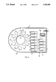
- FIG. 3 is a top view of the fog generator of FIGS. 1 and 2 with parts removed to show internal structure;
- FIG. 4 is a bottom view of the fog generator of FIGS. 1 and 2;
- FIG. 5 is a diagram illustrating the electrical circuit in the fog generator of FIGS. 1-4;
- FIG. 6 is a view corresponding to FIG. 2 but illustrating another preferred embodiment of the invention.
- FIG. 7 is a view corresponding to FIG. 3 but illustrating the embodiment of FIG. 6.
- the fog generator illlustrated in FIGS. 1-5 comprises a housing, generally designated 2, constituted of two sections: an air-blower section 2a, in which a flow of air (or other gas) is generated, and a fog generator section 2b, in which a fog is generated by means of ultrasonic transducers located in that section.
- the air blower section 2a is closed by a cover 4, having an inlet grid 6 through which the air is drawn into the apparatus.
- the fog generator section 2b is closed by a cover 7 having an outlet duct 8 through which the generated fog is discharged.
- the fog generated within the device and discharged via outlet duct 8 is particularly useful in horticulture for aeroponically or conventionally growing plants, but may be used in many other applications, such as humidifiers, nebulizers, and the like.
- Housing 2 includes a horizontal partition 10.
- One part 10a of this partition divides the air-blower section 2a into an upper compartment 12 containing an air blower 14, and a lower compartment 16 containing a plurality of electrical drivers 18 for a plurality of ultrasonic transducers 20 included in the fog generator section 2b.
- a second part 10b of partition 10 divides the fog generator section 2b of the apparatus into an upper compartment 21 including a liquid reservoir 22 of annular configuration, and a lower compartment 24 communicating directly with compartment 16 of the air-blower section 2a.
- the plurality of ultrasonic transducers 20 are fixed in a circular array to partition 10, such as to be immersed in the liquid within the liquid reservoir 22.
- a cylindrical air duct 26 passes through partition 10 centrally of the annular liquid reservoir 22 and the array of ultrasonic transducers 20.
- a dome-shaped deflector 28, of semi-spherical configuration, is fixed above the outlet end of air duct 26.
- the open end of deflector 28 is of larger diameter than air duct 26 such that the inner surface of the open end of the deflector projects outwardly of the air duct and overlies the inner end of the annular liquid reservoir 22.
- a conically-shaped outlet duct 30 is secured to the housing section 2b, with the larger-diameter end of the duct circumscribing the ultrasonic transducers 20 and overlying the outer end of the annular liquid reservoir 22.
- the outer, smaller-diameter end 30b of duct 30 is spaced below the upper end 7a of cover 7, to which is secured a cylindrical outlet duct 8, as shown in FIG. 1, for discharging the generated fog.
- the liquid within the annular reservoir 22 is maintained at a constant level by a float 32 operating a valve 34 controlling the inletting of the water via an inlet tube 36 (FIGS. 1 and 3).
- Float 32 maintains the liquid at the optimum level within reservoir 22 to immerse all the ultrasonic transducers 20 which, when energized by their drivers 18, atomize the liquid.
- An annular array of baffles 38 fixed to partition 10 in the spaces between the ultrasonic transducers 20 and projecting above the level of the liquid within the reservoir 22, acts as barriers suppressing the formation of waves in the liquid when the blower 14 and the ultrasonic transducers 20 are operated.
- Compartment 12 including the air blower 14, may also include a power supply 40 (FIG. 3) and a plurality of fuses 42 These electrical components, as well as the drivers 18 for the ultrasonic transducers 20 in compartment 16, are cooled by the air flow produced by blower 14.
- a reed switch 44 (FIG. 3) is floatingly mounted to turn-off the power supply, should the water level in the reservoir 22 drop below a minimum value, to protect the ultrasonic transducers 20.
- the fog generator illustrated in the drawings operates as follows:
- air blower 14 When air blower 14 is energized, it draws air via the inlet grid 6 in cover 4, causing the air to pass over the power supply 40 and the fuses 42 before reaching inlet 14a (FIG. 1) of the air blower. The air is discharged from the air blower through an outlet opening 14b (FIG. 4) in partition 10, into the lower compartment 16, and is circulated over the ultrasonic transducer drivers 18 before being directed to compartment 24 underlying the fog generator section 2b of the housing.
- the air is passed through the inlet duct 26 centrally of the annular reservoir 22 and the circular array of ultrasonic transducers 20 immersed in the liquid in that reservoir. As shown by the arrows in FIG. 2, the air is then deflected by the inner surface of the dome-shaped deflector 28 back towards the liquid level within reservoir 22, and then transversely across the reservoir so as to become intimately mixed with the liquid atomized by the ultrasonic transducers 20. Baffles 38 between the ultrasonic transducers suppress the formation of waves.
- the operation of the ultrasonic transducers 20 directs the atomized liquid upwardly towards the inner surface of the conical duct 30. Heavy particles of liquid tend to coalesce on the inner surface of the duct and drip back into reservoir 22, whereas the lighter particles, intimately mixed with the air, pass through the outlet opening 30b of duct 30 and through the cylindrical outlet duct 8.
- FIG. 5 illustrates the electrical circuitry for driving the ultrasonic transducers 20. While the ultrasonic transducers 20 are immersed in the liquid within reservoir 22, their drivers 18 are disposed in the electrical circuitry compartment 16, remote from the transducers, so as to enable them to be cooled by the air from the blower 12 passing through compartment 16 before reaching the fog generator section 2b of the device. This arrangement also facilitates maintenance.
- the electrical circuitry includes a full-wave rectifier FWR which supplies, in parallel, the power to the drivers 18 for the ultrasonic transducers 20.
- Each driver 18 includes an oscillator OSC, outputting a voltage at the appropriate frequency (10 KHz-4.6 MHz) to the respective transducer 20.
- Each driver 18 further includes a transistor Q 1 which serves as a base-current regulator for its respective oscillator OSC.
- RFI radio frequency interference
- each ultrasonic transducer 20 is housed within a metal shielding box schematically illustrated by broken lines 50.
- each driver 18, including its oscillator within shielding box 50 is located in compartment 16 remote from its respective ultrasonic transducer 20 located in the liquid reservoir 22.
- Each ultrasonic transducer 20 is connected to its respective driver by a pair of wires enclosed within a shielding cable 52 (FIGS. 2 and 5) electrically connected to the metal shielding box 50 housing the oscillator OSC for the respective ultrasonic transducer.
- the above electrical system provides a number of advantages: It permits the drivers 18 for the ultrasonic transducers 20 to be remotely located from the respective transducers and to be cooled by the gas flow from the blower 14.
- the illustrated circuitry maintains the electrodes of the ultrasonic transducers 20 which are in contact with the water all at the same potential, so as to prevent electrolysis of the water.
- the fog generated by the described apparatus and discharged via the outlet duct 8 is particularly useful for aeroponically growing plants, but may be used in many other applications, e.g. humidifiers, nebulizers, etc.
- the gas may be air and/or other gases, such as carbon dioxide, nitrogen, or the like.
- FIGS. 6 and 7 The fog generator illustrated in FIGS. 6 and 7 is very similar to that illustrated in FIGS. 1-5. To facilitate understanding, similar parts are correspondingly numbered.
- the housing includes a plurality of tubes 102 each overlying one of the transducers 20 for conducting the atomized liquid out of the housing. All of the tubes 102 are enclosed by the cover 7 having the outlet duct through which the generated fog is discharged.
- the fog generator includes a plate 104 which is fixed to the central gas inlet duct 26.
- Plate 104 is spaced over and closes the top of the reservoir 22.
- the tubes 102 are fixed to plate 104 in alignment with their respective transducers 20 such that the lower end of each tube is spaced slightly above the water within the reservoir 22 in alignment with its respective transducer.
- the fog generator illustrated in FIGS. 6 and 7 also includes the dome-shaped deflector 28 of semi-spherical configuration fixed to the inlet duct 26 and of larger diameter than that duct.
- the open end of deflector 28 is secured to all the tubes 102, so that while the deflector also deflects the air from the inlet duct 26 towards the reservoir 22, this air does not actually enter compartment 21 containing the reservoir 22 but rather is deflected by plate 104 upwardly towards the discharge outlet.
- Compartment 21 containing the reservoir 22 is supplied with the air via a pair of two further inlet ducts 106 passing through partition 10b from the lower compartment 24 into the reservoir compartment 25 and terminating below plate 104 securing the tubes 102.
- This air is deflected by plate 104 back towards the surface of the water in reservoir 22, as shown by the arrows in FIG. 6, and flows through the tubes 102 to pick up the liquid atomized by the transducers 20.
- the fog generator illustrated in FIGS. 6 and 7 is otherwise constructed and operates in substantially the same manner as described above with respect to FIGS. 1-5.
- the float-operated valve and the reed switch may be replaced by other forms of liquid level detectors, such as electrical detectors.
- the air blower 14 may be disposed outside of the housing enclosed by cover 4.
Abstract
A fog generator includes a reservoir for a liquid to be atomized, a plurality of ultrasonic transducers disposed in spaced relation to each other in the reservoir so as to be submerged within the liquid therein, a gas inlet duct extending through the reservoir, and a dome-shaped deflector overlying, and of larger diameter than, the gas inlet duct to deflect the gas flowing through the duct back towards the reservor to pick up liquid atomized by the transducers.
Description
The present invention relates to a fog generator, and particularly to one useful in horticulture for growing plants aeroponically, or conventionally.
The invention is particularly useful in the fog-generator method for growing plants aeroponically (i.e. in air, rather than in soil), such as described in our prior U.S. Pat. No. 5,136,804. In such a method, the plant roots, and also the shoots and foliage, are subjected to a fog of atomized water, which may include other additives such as fertilizers, fungicides, etc. Utilizing a fog generator has a number of advantages over a water sprayer. Thus, when sprayers are used, they supply water at a relatively high rate so they must be intermittently operated, whereas a fog generator, supplying water at a much lower rate, can be continuously operated. As a result, utilizing a fog generator reduces the possibility of "stress drying" or "salting" of the plants which may occur in sprayer systems during the periods when the sprayers are not operated.
An object of the present invention is to provide a fog generator which can efficiently supply copious quantities of finely atomized liquid, or fog.
According to one aspect of the present invention, there is provided a fog generator, comprising: a housing including a reservoir for a liquid to be atomized; a plurality of ultrasonic transducers disposed in spaced relation to each other in the reservoir so as to be submerged within the liquid therein; and gas directing means for directing a flow of gas across the liquid in the reservoir; the gas directing means including a gas inlet duct extending through the reservoir, and a dome-shaped deflector overlying, and of larger diameter than, the gas inlet duct to deflect the gas flowing through the duct back towards the reservor to pick up liquid atomized by the transducers.
According to another aspect of the present invention, there is provided a fog generator, comprising: a housing including a reservoir for a liquid to be atomized; a plurality of ultrasonic transducers disposed in spaced relation to each other in the reservoir so as to be submerged within the liquid therein; gas directing means for directing a flow of gas across the liquid in the reservoir; and a plurality of baffles fixed in the reservoir in the spaces between the ultrasonic transducers to act as barriers suppressing the formation of waves in the liquid between the ultrasonic transducers. The ultrasonic transducers are disposed in a circular array and the baffles are also disposed in a circular array between the ultrasonic transducers.
As will be described more particularly below, a fog generator constructed in accordance with the foregoing features can efficiently produce large quantities of fog, particularly useful in horticulture for aeroponically growing plants. The fog produced by such a generator may have an average particle size of about five microns, such that the fog effectively penetrates all the spaces in the roots of the plants in the aeroponic enclosure and, if desired, also in the shoots and foliage of such plants, as described for example in the above-cited patent application.
Further features and advantages of the invention will be apparent from the description below.
The invention is herein described, by way of example only, with reference to the accompanying drawings, wherein:
FIG. 1 is a three-dimensional view, partly exploded and broken-away to show internal structure, of one form of fog generator constructed in accordance with a preferred embodiment of the present invention;
FIG. 2 is a sectional view of the fog generator of FIG. 1;
FIG. 3 is a top view of the fog generator of FIGS. 1 and 2 with parts removed to show internal structure;
FIG. 4 is a bottom view of the fog generator of FIGS. 1 and 2;
FIG. 5 is a diagram illustrating the electrical circuit in the fog generator of FIGS. 1-4;
FIG. 6 is a view corresponding to FIG. 2 but illustrating another preferred embodiment of the invention; and
FIG. 7 is a view corresponding to FIG. 3 but illustrating the embodiment of FIG. 6.
The fog generator illlustrated in FIGS. 1-5 comprises a housing, generally designated 2, constituted of two sections: an air-blower section 2a, in which a flow of air (or other gas) is generated, and a fog generator section 2b, in which a fog is generated by means of ultrasonic transducers located in that section. The air blower section 2a is closed by a cover 4, having an inlet grid 6 through which the air is drawn into the apparatus. The fog generator section 2b is closed by a cover 7 having an outlet duct 8 through which the generated fog is discharged. The fog generated within the device and discharged via outlet duct 8 is particularly useful in horticulture for aeroponically or conventionally growing plants, but may be used in many other applications, such as humidifiers, nebulizers, and the like.
The plurality of ultrasonic transducers 20 are fixed in a circular array to partition 10, such as to be immersed in the liquid within the liquid reservoir 22. A cylindrical air duct 26 passes through partition 10 centrally of the annular liquid reservoir 22 and the array of ultrasonic transducers 20. A dome-shaped deflector 28, of semi-spherical configuration, is fixed above the outlet end of air duct 26. The open end of deflector 28 is of larger diameter than air duct 26 such that the inner surface of the open end of the deflector projects outwardly of the air duct and overlies the inner end of the annular liquid reservoir 22. A conically-shaped outlet duct 30 is secured to the housing section 2b, with the larger-diameter end of the duct circumscribing the ultrasonic transducers 20 and overlying the outer end of the annular liquid reservoir 22. The outer, smaller-diameter end 30b of duct 30 is spaced below the upper end 7a of cover 7, to which is secured a cylindrical outlet duct 8, as shown in FIG. 1, for discharging the generated fog.
The liquid within the annular reservoir 22 is maintained at a constant level by a float 32 operating a valve 34 controlling the inletting of the water via an inlet tube 36 (FIGS. 1 and 3). Float 32 maintains the liquid at the optimum level within reservoir 22 to immerse all the ultrasonic transducers 20 which, when energized by their drivers 18, atomize the liquid. An annular array of baffles 38, fixed to partition 10 in the spaces between the ultrasonic transducers 20 and projecting above the level of the liquid within the reservoir 22, acts as barriers suppressing the formation of waves in the liquid when the blower 14 and the ultrasonic transducers 20 are operated.
The fog generator illustrated in the drawings operates as follows:
When air blower 14 is energized, it draws air via the inlet grid 6 in cover 4, causing the air to pass over the power supply 40 and the fuses 42 before reaching inlet 14a (FIG. 1) of the air blower. The air is discharged from the air blower through an outlet opening 14b (FIG. 4) in partition 10, into the lower compartment 16, and is circulated over the ultrasonic transducer drivers 18 before being directed to compartment 24 underlying the fog generator section 2b of the housing.
The air is passed through the inlet duct 26 centrally of the annular reservoir 22 and the circular array of ultrasonic transducers 20 immersed in the liquid in that reservoir. As shown by the arrows in FIG. 2, the air is then deflected by the inner surface of the dome-shaped deflector 28 back towards the liquid level within reservoir 22, and then transversely across the reservoir so as to become intimately mixed with the liquid atomized by the ultrasonic transducers 20. Baffles 38 between the ultrasonic transducers suppress the formation of waves.
The operation of the ultrasonic transducers 20 directs the atomized liquid upwardly towards the inner surface of the conical duct 30. Heavy particles of liquid tend to coalesce on the inner surface of the duct and drip back into reservoir 22, whereas the lighter particles, intimately mixed with the air, pass through the outlet opening 30b of duct 30 and through the cylindrical outlet duct 8.
FIG. 5 illustrates the electrical circuitry for driving the ultrasonic transducers 20. While the ultrasonic transducers 20 are immersed in the liquid within reservoir 22, their drivers 18 are disposed in the electrical circuitry compartment 16, remote from the transducers, so as to enable them to be cooled by the air from the blower 12 passing through compartment 16 before reaching the fog generator section 2b of the device. This arrangement also facilitates maintenance.
As shown in FIG. 5, the electrical circuitry includes a full-wave rectifier FWR which supplies, in parallel, the power to the drivers 18 for the ultrasonic transducers 20. Each driver 18 includes an oscillator OSC, outputting a voltage at the appropriate frequency (10 KHz-4.6 MHz) to the respective transducer 20. Each driver 18 further includes a transistor Q1 which serves as a base-current regulator for its respective oscillator OSC. RFI (radio frequency interference) is suppressed by a plurality of capacitors and a common mode choke CMC1 between the latter regulator and its respective oscillator OSC, and by a second common mode choke CMC2 between the oscillator and its respective ultrasonic transducer 20.
The oscillator OSC for each ultrasonic transducer 20 is housed within a metal shielding box schematically illustrated by broken lines 50. As indicated earlier, each driver 18, including its oscillator within shielding box 50, is located in compartment 16 remote from its respective ultrasonic transducer 20 located in the liquid reservoir 22. Each ultrasonic transducer 20 is connected to its respective driver by a pair of wires enclosed within a shielding cable 52 (FIGS. 2 and 5) electrically connected to the metal shielding box 50 housing the oscillator OSC for the respective ultrasonic transducer.
The above electrical system provides a number of advantages: It permits the drivers 18 for the ultrasonic transducers 20 to be remotely located from the respective transducers and to be cooled by the gas flow from the blower 14. In addition, the illustrated circuitry maintains the electrodes of the ultrasonic transducers 20 which are in contact with the water all at the same potential, so as to prevent electrolysis of the water.
As indicated earlier, the fog generated by the described apparatus and discharged via the outlet duct 8 is particularly useful for aeroponically growing plants, but may be used in many other applications, e.g. humidifiers, nebulizers, etc. The gas may be air and/or other gases, such as carbon dioxide, nitrogen, or the like.
The fog generator illustrated in FIGS. 6 and 7 is very similar to that illustrated in FIGS. 1-5. To facilitate understanding, similar parts are correspondingly numbered.
In the fog generator of FIGS. 6 and 7 the common outer duct 30 is omitted. Instead, the housing includes a plurality of tubes 102 each overlying one of the transducers 20 for conducting the atomized liquid out of the housing. All of the tubes 102 are enclosed by the cover 7 having the outlet duct through which the generated fog is discharged.
More particularly, the fog generator includes a plate 104 which is fixed to the central gas inlet duct 26. Plate 104 is spaced over and closes the top of the reservoir 22. The tubes 102 are fixed to plate 104 in alignment with their respective transducers 20 such that the lower end of each tube is spaced slightly above the water within the reservoir 22 in alignment with its respective transducer. In the example illustrated in FIGS. 6 and 7, there are twenty-two transducers 20 arranged in a circular array around the inlet duct 26, and therefore there would be twenty-two tubes 102. This number can of course be increased or reduced; preferably, in the particular application described herein, there are at least ten transducers 20 each provided with one of the tubes 102.
The fog generator illustrated in FIGS. 6 and 7 also includes the dome-shaped deflector 28 of semi-spherical configuration fixed to the inlet duct 26 and of larger diameter than that duct. In this case, the open end of deflector 28 is secured to all the tubes 102, so that while the deflector also deflects the air from the inlet duct 26 towards the reservoir 22, this air does not actually enter compartment 21 containing the reservoir 22 but rather is deflected by plate 104 upwardly towards the discharge outlet.
It will thus be seen that part of the gas from the gas compartment 24 enters the reservoir compartment 21 and flows through the tubes 102 as it picks up liquid atomized by the transducers 20. Another part of the gas flows through the central duct 26, is deflected downwardly by deflector 28 towards plate 104, and then upwardly out through the discharge outlet in cover 7, as it also picks up and mixes with the liquid atomized by the transducers 20 exiting from the tubes 102.
It has been found that such an arrangement produces very large quantities of fog for the relative size of the unit.
The fog generator illustrated in FIGS. 6 and 7 is otherwise constructed and operates in substantially the same manner as described above with respect to FIGS. 1-5.
It will be appreciated that many further variations may be made. For example, the float-operated valve and the reed switch (32 and 44, respectively, may be replaced by other forms of liquid level detectors, such as electrical detectors. In addition, the air blower 14 may be disposed outside of the housing enclosed by cover 4.
Many other variations, modifications and applications of the invention will be apparent.
Claims (19)
1. A fog generator, comprising:
a housing including a reservoir for a liquid to be atomized;
a plurality of ultrasonic transducers disposed in spaced relation to each other in said reservoir so as to be submerged within the liquid therein;
and gas directing means for directing a flow of gas across the liquid in the reservoir;
said gas directing means including a gas inlet duct extending through said reservoir, and a dome-shaped deflector overlying, and of larger diameter than, said gas inlet duct to deflect the gas flowing through said duct back towards the reservor to pick up liquid atomized by said transducers.
2. The fog generator according to claim 1, wherein said ultrasonic transducers are disposed in a circular array, and said gas inlet duct extends through said circular array of transducers.
3. The fog generator according to claim 1, wherein the outlet end of the inlet duct is of cylindrical configuration, and the dome-shaped deflector is of semi-spherical configuration and of larger diameter than the outlet end of said inlet duct.
4. The fog generator according to claim 1, wherein said reservoir includes a plurality of baffles fixed in the reservoir in the spaces between the ultrasonic transducers to suppress the formation of waves in the liquid between the ultrasonic transducers.
5. The fog generator according to claim 1, wherein said housing further includes a conically-shaped outlet duct having its larger diameter end circumscribing the ultrasonic transducers and overlying the reservoir so as to receive, and to return to the reservoir, large droplets of the liquid atomized by the ultrasonic transducers.
6. The for generator according to claim 1, wherein said gas directing means further includes a gas chamber defined by a partition to which said ultrasonic transducers are fixed, said inlet duct passing through said partition to direct the flow of gas from said gas chamber into said reservoir.
7. The fog generator according to claim 6, wherein said housing further includes a blower located in a blower compartment laterally of said reservoir and gas compartment, and communicating with said gas compartment.
8. The fog generator according to claim 7, wherein said blower compartment is defined by a second partition also defining an electrical circuitry compartment including electrical drivers for said ultrasonic transducers, the gas being directed from said blower compartment to the gas compartment to also cool the electrical circuitry components in said electrical circuitry compartment.
9. The fog generator according to claim 8, wherein additional electrical components are located in said blower compartment, said housing including a gas inlet to the blower located so as to draw the air past said other electrical components to cool them before the gas arrives at said gas inlet.
10. The fog generator according to claim 8, wherein each of said electrical devices is disposed in a shielded housing in said electrical circuitry compartment, and is connected to its respective ultrasonic transducer in the reservoir by a shielded cable electrically connected to its respective shielded housing.
11. A fog generator, comprising :
a housing including a reservoir for a liquid to be atomized;
a plurality of ultrasonic transducers disposed in spaced relation to each other in said reservoir so as to be submerged within the liquid therein;
gas directing means for directing a flow of gas across the liquid in the reservoir;
and a plurality of baffles fixed in the reservoir in the spaces between the ultrasonic transducers to act as barriers suppressing the formation of waves in the liquid between the ultrasonic transducers;
said ultrasonic transducers being disposed in a circular array, and said baffles also being disposed in a circular array between the ultrasonic transducers.
12. The fog generator according to claim 11, wherein said reservoir is of annular configuration, and said gas directing means includes a gas inlet centrally of said reservoir and said circular array of ultrasonic transducers therein.
13. The fog generator according to claim 12, wherein said gas inlet includes an inlet duct coaxial with said circular array of ultrasonic transducers and having an outlet end above the level of the liquid in the reservoir; and wherein said generator further includes a dome-shaped deflector overlying, and of larger diameter than, said inlet duct so as to deflect the gas flowing therethrough back to the liquid in the reservoir to pick up the liquid atomized by the ultrasonic transducers.
14. The fog generator according to claim 13, wherein the outlet end of the inlet duct is of cylindrical configuration, and wherein the dome-shaped deflector is of semi-spherical configuration and of larger diameter than the outlet end of said inlet duct.
15. A fog generator according to claim 11, wherein the housing includes a plurality of tubes each overlying one of said transducers for conducting the atomized liquid out of said housing.
16. The fog generator according to claim 15, wherein there are at least ten transducers and ten of said tubes each overlying one of said transducers.
17. The fog generator according to claim 15, wherein said tubes are carried by a plate which is spaced over and closes the top of said reservoir.
18. The fog generator according to claim 17, wherein said gas directing means includes at least one further gas inlet duct for directing the gas into the space between said plate and said reservoir.
19. The fog generator according to claim 18, wherein there are at least two of said further gas inlet ducts.
Applications Claiming Priority (4)
| Application Number | Priority Date | Filing Date | Title |
|---|---|---|---|
| IL101967 | 1992-05-22 | ||
| IL101967A IL101967A0 (en) | 1992-05-22 | 1992-05-22 | Fog generator |
| IL104231 | 1992-12-25 | ||
| IL104231A IL104231A0 (en) | 1992-05-22 | 1992-12-25 | Fog generator |
Publications (1)
| Publication Number | Publication Date |
|---|---|
| US5300260A true US5300260A (en) | 1994-04-05 |
Family
ID=26322453
Family Applications (1)
| Application Number | Title | Priority Date | Filing Date |
|---|---|---|---|
| US08/049,381 Expired - Fee Related US5300260A (en) | 1992-05-22 | 1993-04-21 | Fog generator |
Country Status (3)
| Country | Link |
|---|---|
| US (1) | US5300260A (en) |
| EP (1) | EP0571316A1 (en) |
| IL (1) | IL104231A0 (en) |
Cited By (34)
| Publication number | Priority date | Publication date | Assignee | Title |
|---|---|---|---|---|
| US5908158A (en) * | 1992-10-16 | 1999-06-01 | Sheiman Ultrasonic Research Foundation Party, Ltd. | Ultrasonic nebulising device |
| US5922247A (en) * | 1997-07-28 | 1999-07-13 | Green Clouds Ltd. | Ultrasonic device for atomizing liquids |
| US6127429A (en) * | 1997-02-20 | 2000-10-03 | Degussa-Huls Ag | Ultrasonic atomization for production of aerosols |
| US6361024B1 (en) * | 1999-03-17 | 2002-03-26 | Pwc Technologies, Inc. | Hand-held ultrasonic fog generator |
| WO2003024610A1 (en) | 2001-09-19 | 2003-03-27 | Adiga Kayyani C | Method and device for production, extraction and delivery of mist with ultrafine droplets |
| US20050079124A1 (en) * | 2003-08-06 | 2005-04-14 | Sanderson William D. | Apparatus and method for producing chlorine dioxide |
| US20060115388A1 (en) * | 2002-12-13 | 2006-06-01 | Sanderson William D | Dispersal air scrubber |
| US20060131764A1 (en) * | 2004-12-20 | 2006-06-22 | Weon Yoo S | Faucet-based humidifier |
| US20060213508A1 (en) * | 2005-03-23 | 2006-09-28 | Barnstead/Thermolyne Corporation | Environmental chamber and ultrasonic nebulizer assembly therefor |
| US20070148362A1 (en) * | 2003-10-28 | 2007-06-28 | Mikael Furu | Spay coating unit and method of spray coating |
| US20070224080A1 (en) * | 2006-03-22 | 2007-09-27 | Zimek Technologies Ip, Llc | Ultrasonic Sanitation Device and Associated Methods |
| US20080011873A1 (en) * | 2006-03-28 | 2008-01-17 | Areco Finances Et Technologie - Arfitec | Optimized method of atomizing liquid and a liquid atomizer device for implementing the method |
| US20080299161A1 (en) * | 2005-12-16 | 2008-12-04 | Sanderson William D | Solid Biocide Composition and Sealed Biocide Article |
| US7524454B1 (en) | 2004-08-10 | 2009-04-28 | Zimek Technologies Ip, Llc | Sanitation method for disinfection of enclosed spaces |
| US20090185970A1 (en) * | 2008-01-17 | 2009-07-23 | Sanderson William D | Stable chlorine dioxide tablet |
| US20090232903A1 (en) * | 2005-12-16 | 2009-09-17 | Sanderson William D | Biocide compositions |
| US7712249B1 (en) * | 2007-11-16 | 2010-05-11 | Monster Mosquito Systems, Llc | Ultrasonic humidifier for repelling insects |
| EP1875951A3 (en) * | 2006-07-05 | 2010-09-08 | Ultrasound Brewery | Ultrasonic solution separation apparatus |
| US20100224697A1 (en) * | 2007-11-16 | 2010-09-09 | Monster Mosquito Systems | Ultrasonic humidifier for repelling insects |
| US20110030743A1 (en) * | 2006-03-22 | 2011-02-10 | Zimek Technologies Ip, Llc | Ultrasonic sanitation and disinfecting device and associated methods |
| US8062588B2 (en) | 2006-03-22 | 2011-11-22 | Zimek Technologies Ip, Llc | Ultrasonic sanitation device and associated methods |
| US20120107919A1 (en) * | 2009-06-24 | 2012-05-03 | Igv Institut Fuer Getreideverarbeitung Gmbh | Method for Producing Biomass and Photobioreactor for Cultivating Phototrophic or Mixotrophic Organisms or Cells |
| US8196604B1 (en) | 2010-01-18 | 2012-06-12 | Ricciardi Jonathan J | Deployable automated vent cover device |
| US20120208304A1 (en) * | 2001-06-08 | 2012-08-16 | Semiconductor Energy Laboratory Co., Ltd. | Process of manufacturing luminescent device |
| US8359984B1 (en) | 2010-01-18 | 2013-01-29 | Wolf Ii John D | Portable automated vent cover |
| US8382008B1 (en) * | 2005-08-26 | 2013-02-26 | Jonathan J. Ricciardi | Optimized and miniaturized aerosol generator |
| WO2015061450A1 (en) * | 2013-10-22 | 2015-04-30 | James Alan Aamodt | Product display system providing product humidification |
| US20160158788A1 (en) * | 2013-08-08 | 2016-06-09 | Toshiba Mitsubishi-Electric Industrial Systems Corporation | Atomizing apparatus |
| CN106422005A (en) * | 2016-09-22 | 2017-02-22 | 声海电子(深圳)有限公司 | Ultrasonic atomization structure and ultrasonic atomization device using the same |
| US9718078B1 (en) * | 2016-09-30 | 2017-08-01 | Acoustic Arc International Limited | Piezoceramic based atomizer for high viscosity liquids |
| US20180126394A1 (en) * | 2016-11-04 | 2018-05-10 | Verisure Sàrl | Smoke generator with deflector |
| US10823438B1 (en) * | 2019-09-05 | 2020-11-03 | Altapure, Llc | Vent bypass system |
| US20200368383A1 (en) * | 2018-12-21 | 2020-11-26 | Foshan Nanhai Keri Electronic Co.,Ltd | Method for forming changeable mist of aromatherapy machine and applied aromatherapy machine |
| US20220044535A1 (en) * | 2018-12-18 | 2022-02-10 | Essence Security International (E.S.I.) Ltd. | Obscuration cloud generator |
Families Citing this family (4)
| Publication number | Priority date | Publication date | Assignee | Title |
|---|---|---|---|---|
| GB9412676D0 (en) * | 1994-06-23 | 1994-08-10 | Jem Smoke Machine Co | Improvements in or relating to a method of creating an effect |
| FR2721839B1 (en) * | 1994-07-04 | 1996-10-25 | Imra Europe Sa | SPRAYING DEVICE, ESPECIALLY WATER IN THE FORM OF MICRO-DROPLETS, CAPABLE OF OPERATING IN A NON-STATIONARY MEDIUM |
| ES2114403B1 (en) * | 1994-07-29 | 1999-01-01 | Tecnidex Tecnicas De Desinfecc | WATER STEAM NEBULIZING GENERATOR USING ULTRASONICS. |
| WO2012127512A1 (en) * | 2011-03-23 | 2012-09-27 | Giuseppe Cascone | Ultrasonic atomizer for liquid substances and solutions |
Citations (7)
| Publication number | Priority date | Publication date | Assignee | Title |
|---|---|---|---|---|
| JPS5434113A (en) * | 1977-08-22 | 1979-03-13 | Mitsubishi Electric Corp | Supersonic atomizer |
| JPS555760A (en) * | 1978-06-30 | 1980-01-16 | Nomura Sangyo Kk | Generating unit for fume by ultrasonic wave |
| JPS60129541A (en) * | 1983-12-16 | 1985-07-10 | Matsushita Seiko Co Ltd | Supersonic type humidifier |
| DE3516144A1 (en) * | 1985-05-04 | 1986-11-06 | Kalwar, Klaus, 4802 Halle | Method and apparatus for generating aerosols |
| US4731204A (en) * | 1983-07-08 | 1988-03-15 | Sanyo Electric Co., Ltd. | Humidifier unit for refrigerated display cabinets |
| US4776990A (en) * | 1986-11-14 | 1988-10-11 | Rhinotherm Netzer Sereni | Method and apparatus for nebulizing a liquid |
| US4911866A (en) * | 1988-11-25 | 1990-03-27 | The Walt Disney Company | Fog producing apparatus |
-
1992
- 1992-12-25 IL IL104231A patent/IL104231A0/en unknown
-
1993
- 1993-04-21 US US08/049,381 patent/US5300260A/en not_active Expired - Fee Related
- 1993-05-24 EP EP93630041A patent/EP0571316A1/en not_active Withdrawn
Patent Citations (7)
| Publication number | Priority date | Publication date | Assignee | Title |
|---|---|---|---|---|
| JPS5434113A (en) * | 1977-08-22 | 1979-03-13 | Mitsubishi Electric Corp | Supersonic atomizer |
| JPS555760A (en) * | 1978-06-30 | 1980-01-16 | Nomura Sangyo Kk | Generating unit for fume by ultrasonic wave |
| US4731204A (en) * | 1983-07-08 | 1988-03-15 | Sanyo Electric Co., Ltd. | Humidifier unit for refrigerated display cabinets |
| JPS60129541A (en) * | 1983-12-16 | 1985-07-10 | Matsushita Seiko Co Ltd | Supersonic type humidifier |
| DE3516144A1 (en) * | 1985-05-04 | 1986-11-06 | Kalwar, Klaus, 4802 Halle | Method and apparatus for generating aerosols |
| US4776990A (en) * | 1986-11-14 | 1988-10-11 | Rhinotherm Netzer Sereni | Method and apparatus for nebulizing a liquid |
| US4911866A (en) * | 1988-11-25 | 1990-03-27 | The Walt Disney Company | Fog producing apparatus |
Non-Patent Citations (2)
| Title |
|---|
| Patent Abstracts of Japan vol. 004, No. 030 (C 002) 15 Mar. 1980 & JP A 55 005 760 (Nomura Sangyo KK) 30 Jun. 1978. * |
| Patent Abstracts of Japan vol. 004, No. 030 (C-002) 15 Mar. 1980 & JP-A-55 005 760 (Nomura Sangyo KK) 30 Jun. 1978. |
Cited By (47)
| Publication number | Priority date | Publication date | Assignee | Title |
|---|---|---|---|---|
| US5908158A (en) * | 1992-10-16 | 1999-06-01 | Sheiman Ultrasonic Research Foundation Party, Ltd. | Ultrasonic nebulising device |
| US6127429A (en) * | 1997-02-20 | 2000-10-03 | Degussa-Huls Ag | Ultrasonic atomization for production of aerosols |
| US5922247A (en) * | 1997-07-28 | 1999-07-13 | Green Clouds Ltd. | Ultrasonic device for atomizing liquids |
| US6361024B1 (en) * | 1999-03-17 | 2002-03-26 | Pwc Technologies, Inc. | Hand-held ultrasonic fog generator |
| US20120208304A1 (en) * | 2001-06-08 | 2012-08-16 | Semiconductor Energy Laboratory Co., Ltd. | Process of manufacturing luminescent device |
| WO2003024610A1 (en) | 2001-09-19 | 2003-03-27 | Adiga Kayyani C | Method and device for production, extraction and delivery of mist with ultrafine droplets |
| US6883724B2 (en) | 2001-09-19 | 2005-04-26 | Nanomist Systems, Llc | Method and device for production, extraction and delivery of mist with ultrafine droplets |
| US20060115388A1 (en) * | 2002-12-13 | 2006-06-01 | Sanderson William D | Dispersal air scrubber |
| US7695692B2 (en) | 2003-08-06 | 2010-04-13 | Sanderson William D | Apparatus and method for producing chlorine dioxide |
| US20050079124A1 (en) * | 2003-08-06 | 2005-04-14 | Sanderson William D. | Apparatus and method for producing chlorine dioxide |
| US20070148362A1 (en) * | 2003-10-28 | 2007-06-28 | Mikael Furu | Spay coating unit and method of spray coating |
| US20110081483A1 (en) * | 2003-10-28 | 2011-04-07 | Metso Paper, Inc. | Method of Spray Coating |
| US7524454B1 (en) | 2004-08-10 | 2009-04-28 | Zimek Technologies Ip, Llc | Sanitation method for disinfection of enclosed spaces |
| US7434791B2 (en) * | 2004-12-20 | 2008-10-14 | Yoo Sung Weon | Faucet-based humidifier |
| US20060131764A1 (en) * | 2004-12-20 | 2006-06-22 | Weon Yoo S | Faucet-based humidifier |
| US20060213508A1 (en) * | 2005-03-23 | 2006-09-28 | Barnstead/Thermolyne Corporation | Environmental chamber and ultrasonic nebulizer assembly therefor |
| US7686285B2 (en) | 2005-03-23 | 2010-03-30 | Barnstead Thermolyne Corporation | Environmental chamber and ultrasonic nebulizer assembly therefor |
| US8382008B1 (en) * | 2005-08-26 | 2013-02-26 | Jonathan J. Ricciardi | Optimized and miniaturized aerosol generator |
| US20080299161A1 (en) * | 2005-12-16 | 2008-12-04 | Sanderson William D | Solid Biocide Composition and Sealed Biocide Article |
| US20090232903A1 (en) * | 2005-12-16 | 2009-09-17 | Sanderson William D | Biocide compositions |
| US20070224080A1 (en) * | 2006-03-22 | 2007-09-27 | Zimek Technologies Ip, Llc | Ultrasonic Sanitation Device and Associated Methods |
| US7959859B2 (en) * | 2006-03-22 | 2011-06-14 | Sparks David W | Ultrasonic sanitation device and associated methods |
| US8609029B2 (en) | 2006-03-22 | 2013-12-17 | Zimek Technologies Ip, Llc | Ultrasonic sanitation and disinfecting device and associated methods |
| US8062588B2 (en) | 2006-03-22 | 2011-11-22 | Zimek Technologies Ip, Llc | Ultrasonic sanitation device and associated methods |
| US20110030743A1 (en) * | 2006-03-22 | 2011-02-10 | Zimek Technologies Ip, Llc | Ultrasonic sanitation and disinfecting device and associated methods |
| US20080011873A1 (en) * | 2006-03-28 | 2008-01-17 | Areco Finances Et Technologie - Arfitec | Optimized method of atomizing liquid and a liquid atomizer device for implementing the method |
| EP1875951A3 (en) * | 2006-07-05 | 2010-09-08 | Ultrasound Brewery | Ultrasonic solution separation apparatus |
| US20100224697A1 (en) * | 2007-11-16 | 2010-09-09 | Monster Mosquito Systems | Ultrasonic humidifier for repelling insects |
| US8296993B2 (en) * | 2007-11-16 | 2012-10-30 | Monster Mosquito Systems, Llc | Ultrasonic humidifier for repelling insects |
| US7712249B1 (en) * | 2007-11-16 | 2010-05-11 | Monster Mosquito Systems, Llc | Ultrasonic humidifier for repelling insects |
| US7666384B2 (en) | 2008-01-17 | 2010-02-23 | Sanderson William D | Stable chlorine dioxide tablet |
| US20090185970A1 (en) * | 2008-01-17 | 2009-07-23 | Sanderson William D | Stable chlorine dioxide tablet |
| US20120107919A1 (en) * | 2009-06-24 | 2012-05-03 | Igv Institut Fuer Getreideverarbeitung Gmbh | Method for Producing Biomass and Photobioreactor for Cultivating Phototrophic or Mixotrophic Organisms or Cells |
| US8196604B1 (en) | 2010-01-18 | 2012-06-12 | Ricciardi Jonathan J | Deployable automated vent cover device |
| US8359984B1 (en) | 2010-01-18 | 2013-01-29 | Wolf Ii John D | Portable automated vent cover |
| US20160158788A1 (en) * | 2013-08-08 | 2016-06-09 | Toshiba Mitsubishi-Electric Industrial Systems Corporation | Atomizing apparatus |
| US10456802B2 (en) * | 2013-08-08 | 2019-10-29 | Toshiba Mitsubihshi-Electric Industrial Systems Corporation | Atomizing apparatus |
| WO2015061450A1 (en) * | 2013-10-22 | 2015-04-30 | James Alan Aamodt | Product display system providing product humidification |
| CN106422005A (en) * | 2016-09-22 | 2017-02-22 | 声海电子(深圳)有限公司 | Ultrasonic atomization structure and ultrasonic atomization device using the same |
| US9718078B1 (en) * | 2016-09-30 | 2017-08-01 | Acoustic Arc International Limited | Piezoceramic based atomizer for high viscosity liquids |
| US20180126394A1 (en) * | 2016-11-04 | 2018-05-10 | Verisure Sàrl | Smoke generator with deflector |
| US11045820B2 (en) * | 2016-11-04 | 2021-06-29 | Verisure Sarl | Smoke generator with deflector |
| US11318485B2 (en) | 2016-11-04 | 2022-05-03 | Verisure Sàrl | Smoke generator with deflector |
| US11724269B2 (en) | 2016-11-04 | 2023-08-15 | Verisure Sàr | Smoke generator with deflector |
| US20220044535A1 (en) * | 2018-12-18 | 2022-02-10 | Essence Security International (E.S.I.) Ltd. | Obscuration cloud generator |
| US20200368383A1 (en) * | 2018-12-21 | 2020-11-26 | Foshan Nanhai Keri Electronic Co.,Ltd | Method for forming changeable mist of aromatherapy machine and applied aromatherapy machine |
| US10823438B1 (en) * | 2019-09-05 | 2020-11-03 | Altapure, Llc | Vent bypass system |
Also Published As
| Publication number | Publication date |
|---|---|
| IL104231A0 (en) | 1993-05-13 |
| EP0571316A1 (en) | 1993-11-24 |
Similar Documents
| Publication | Publication Date | Title |
|---|---|---|
| US5300260A (en) | Fog generator | |
| US6883724B2 (en) | Method and device for production, extraction and delivery of mist with ultrafine droplets | |
| EP0107324B1 (en) | Electrostatic sprayhead assembly | |
| US4087495A (en) | Ultrasonic air humidifying apparatus | |
| US20120111961A1 (en) | Grove sprayer | |
| US3249553A (en) | Smoke generator | |
| US5240186A (en) | Portable electrostatic liquid sprayer | |
| JP2005502463A5 (en) | ||
| JPS61287467A (en) | Ultrasonic spray apparatus | |
| KR101981363B1 (en) | Liquid-Agent-Spraying Device, Electrifying/Spraying Head, and Liquid-Agent-Spraying Method | |
| KR101670464B1 (en) | A prevention device of raindrops noise for humidifier | |
| CN111643709A (en) | Nano aerosol disinfection equipment | |
| US7195179B2 (en) | Piezoelectric mist generation device | |
| EP0225193B1 (en) | Spraying nozzle | |
| KR20170067344A (en) | A humidifier with type of verticality spray | |
| JPH09172855A (en) | Treatment of agricultural product | |
| JPH0924315A (en) | Fog generator | |
| JP2007283281A (en) | Ultrasonic atomizing apparatus | |
| GB1120414A (en) | Improvements in or relating to a liquid atomizer | |
| JPS5831227B2 (en) | Ultrasonic fog generator | |
| JPH0579886B2 (en) | ||
| US4269353A (en) | Exhaust operated vaporizer | |
| JP2005144096A (en) | Sprayer with illumination | |
| GB2100147A (en) | Electrostatic spraying | |
| JPH0612837Y2 (en) | Chemical liquid spraying device using static electricity |
Legal Events
| Date | Code | Title | Description |
|---|---|---|---|
| AS | Assignment |
Owner name: SHIRA AEROPONICS (1984) LTD., ISRAEL Free format text: ASSIGNMENT OF ASSIGNORS INTEREST;ASSIGNORS:KESHET, AMIRAM;SHOHAM, YAACOV;REEL/FRAME:006551/0126;SIGNING DATES FROM 19930209 TO 19930404 |
|
| LAPS | Lapse for failure to pay maintenance fees | ||
| FP | Lapsed due to failure to pay maintenance fee |
Effective date: 19980405 |
|
| STCH | Information on status: patent discontinuation |
Free format text: PATENT EXPIRED DUE TO NONPAYMENT OF MAINTENANCE FEES UNDER 37 CFR 1.362 |