US5302402A - Bone-in food packaging article - Google Patents
Bone-in food packaging article Download PDFInfo
- Publication number
- US5302402A US5302402A US07/979,520 US97952092A US5302402A US 5302402 A US5302402 A US 5302402A US 97952092 A US97952092 A US 97952092A US 5302402 A US5302402 A US 5302402A
- Authority
- US
- United States
- Prior art keywords
- patch
- bag
- density polyethylene
- low density
- vinyl acetate
- Prior art date
- Legal status (The legal status is an assumption and is not a legal conclusion. Google has not performed a legal analysis and makes no representation as to the accuracy of the status listed.)
- Expired - Lifetime
Links
Images


Classifications
-
- B—PERFORMING OPERATIONS; TRANSPORTING
- B65—CONVEYING; PACKING; STORING; HANDLING THIN OR FILAMENTARY MATERIAL
- B65D—CONTAINERS FOR STORAGE OR TRANSPORT OF ARTICLES OR MATERIALS, e.g. BAGS, BARRELS, BOTTLES, BOXES, CANS, CARTONS, CRATES, DRUMS, JARS, TANKS, HOPPERS, FORWARDING CONTAINERS; ACCESSORIES, CLOSURES, OR FITTINGS THEREFOR; PACKAGING ELEMENTS; PACKAGES
- B65D75/00—Packages comprising articles or materials partially or wholly enclosed in strips, sheets, blanks, tubes, or webs of flexible sheet material, e.g. in folded wrappers
- B65D75/002—Packages comprising articles or materials partially or wholly enclosed in strips, sheets, blanks, tubes, or webs of flexible sheet material, e.g. in folded wrappers in shrink films
- B65D75/004—Packages comprising articles or materials partially or wholly enclosed in strips, sheets, blanks, tubes, or webs of flexible sheet material, e.g. in folded wrappers in shrink films with auxiliary packaging elements, e.g. protective pads or frames, trays
-
- B—PERFORMING OPERATIONS; TRANSPORTING
- B65—CONVEYING; PACKING; STORING; HANDLING THIN OR FILAMENTARY MATERIAL
- B65B—MACHINES, APPARATUS OR DEVICES FOR, OR METHODS OF, PACKAGING ARTICLES OR MATERIALS; UNPACKING
- B65B25/00—Packaging other articles presenting special problems
- B65B25/06—Packaging slices or specially-shaped pieces of meat, cheese, or other plastic or tacky products
- B65B25/065—Packaging slices or specially-shaped pieces of meat, cheese, or other plastic or tacky products of meat
-
- B—PERFORMING OPERATIONS; TRANSPORTING
- B31—MAKING ARTICLES OF PAPER, CARDBOARD OR MATERIAL WORKED IN A MANNER ANALOGOUS TO PAPER; WORKING PAPER, CARDBOARD OR MATERIAL WORKED IN A MANNER ANALOGOUS TO PAPER
- B31B—MAKING CONTAINERS OF PAPER, CARDBOARD OR MATERIAL WORKED IN A MANNER ANALOGOUS TO PAPER
- B31B2150/00—Flexible containers made from sheets or blanks, e.g. from flattened tubes
- B31B2150/002—Flexible containers made from sheets or blanks, e.g. from flattened tubes by joining superimposed sheets, e.g. with separate bottom sheets
-
- B—PERFORMING OPERATIONS; TRANSPORTING
- B31—MAKING ARTICLES OF PAPER, CARDBOARD OR MATERIAL WORKED IN A MANNER ANALOGOUS TO PAPER; WORKING PAPER, CARDBOARD OR MATERIAL WORKED IN A MANNER ANALOGOUS TO PAPER
- B31B—MAKING CONTAINERS OF PAPER, CARDBOARD OR MATERIAL WORKED IN A MANNER ANALOGOUS TO PAPER
- B31B2155/00—Flexible containers made from webs
- B31B2155/003—Flexible containers made from webs starting from tubular webs
-
- B—PERFORMING OPERATIONS; TRANSPORTING
- B31—MAKING ARTICLES OF PAPER, CARDBOARD OR MATERIAL WORKED IN A MANNER ANALOGOUS TO PAPER; WORKING PAPER, CARDBOARD OR MATERIAL WORKED IN A MANNER ANALOGOUS TO PAPER
- B31B—MAKING CONTAINERS OF PAPER, CARDBOARD OR MATERIAL WORKED IN A MANNER ANALOGOUS TO PAPER
- B31B2170/00—Construction of flexible containers
- B31B2170/20—Construction of flexible containers having multi-layered walls, e.g. laminated or lined
-
- B—PERFORMING OPERATIONS; TRANSPORTING
- B31—MAKING ARTICLES OF PAPER, CARDBOARD OR MATERIAL WORKED IN A MANNER ANALOGOUS TO PAPER; WORKING PAPER, CARDBOARD OR MATERIAL WORKED IN A MANNER ANALOGOUS TO PAPER
- B31B—MAKING CONTAINERS OF PAPER, CARDBOARD OR MATERIAL WORKED IN A MANNER ANALOGOUS TO PAPER
- B31B70/00—Making flexible containers, e.g. envelopes or bags
- B31B70/74—Auxiliary operations
- B31B70/81—Forming or attaching accessories, e.g. opening devices, closures or tear strings
-
- B—PERFORMING OPERATIONS; TRANSPORTING
- B31—MAKING ARTICLES OF PAPER, CARDBOARD OR MATERIAL WORKED IN A MANNER ANALOGOUS TO PAPER; WORKING PAPER, CARDBOARD OR MATERIAL WORKED IN A MANNER ANALOGOUS TO PAPER
- B31B—MAKING CONTAINERS OF PAPER, CARDBOARD OR MATERIAL WORKED IN A MANNER ANALOGOUS TO PAPER
- B31B70/00—Making flexible containers, e.g. envelopes or bags
- B31B70/74—Auxiliary operations
- B31B70/92—Delivering
- B31B70/94—Delivering singly or in succession
- B31B70/946—Delivering singly or in succession the bags being interconnected
-
- B—PERFORMING OPERATIONS; TRANSPORTING
- B65—CONVEYING; PACKING; STORING; HANDLING THIN OR FILAMENTARY MATERIAL
- B65D—CONTAINERS FOR STORAGE OR TRANSPORT OF ARTICLES OR MATERIALS, e.g. BAGS, BARRELS, BOTTLES, BOXES, CANS, CARTONS, CRATES, DRUMS, JARS, TANKS, HOPPERS, FORWARDING CONTAINERS; ACCESSORIES, CLOSURES, OR FITTINGS THEREFOR; PACKAGING ELEMENTS; PACKAGES
- B65D2275/00—Details of sheets, wrappers or bags
- B65D2275/02—Sheets wrappers or bags provided with protective or puncture resistant patches, specially adapted for meat on the bone, e.g. patch bags
Definitions
- This invention relates to the packaging of bone-in food masses such as cuts of meat.
- the invention relates to an article comprising a thermoplastic evacuable heat shrinkable bag - external patch combination, a method for packaging bone-in food mass, and a transportable evacuated sealed package containing bone-in food mass.
- thermoplastic film as flexible packaging material for vacuum packaging perishable food mass is well-known.
- This type of film is relatively thin, e.g. less than 4 mils, so itself is not suitable for packaging bone-in food mass such as meat.
- attempts to use such thin film in bag form to package bone-in sub-primal rib beef cuts are generally unsuccessful because the bone punctures the film.
- the puncture problem is compounded by external abrasion between adjacent packages when they are transported in containers subject to intransit vibration and movement during loading and unloading.
- Another approach was to adhere a puncture guard in the form of a patch on the outer surface of the heat shrinkable bag.
- One form of patch was a plurality of oriented sheets which are laminated in cross-oriented relationship, as for example described in Conant U.S. Pat. No. 4,239,111.
- the manufacturer reported that the non-heat shrinkable patch, which was adhesively bonded to the bag outer surface, tended to delaminate when the evacuated bag was heat shrunk around and onto the bone-in food mass outer surface.
- the aforementioned U.S. Pat. No. 4,755,403 describes a patch formed from a tube comprising an outer layer of 87% linear low density polyethylene (LLDPE), 10% ethylene vinyl acetate (EVA) having 9% vinyl acetate (VA) content, and an inner layer comprising EVA with 28% VA content.
- LLDPE linear low density polyethylene
- EVA ethylene vinyl acetate
- VA vinyl acetate
- the tube must be extruded with powder such as starch particles on the inner layer inside surface to prevent adhesion during extrusion. This is necessary because the primary tube must be reinflated to form the trapped or secondary bubble if the tube is to be biaxially oriented by this method.
- the starch particles are sufficiently spread apart by the two way stretching and thinning of the film, that the collapsed tube becomes self adhering.
- Patent '403 also teaches that irradiative cross linking of the patch is necessary to strengthen the tube sufficiently to permit inflation as a bubble for biaxial orientation. Accordingly, the irradiation step must be performed on the relatively thick primary tube, and relatively high power is needed for this because of the thick-walled tube.
- the patch bag of Patent '403 is relatively expensive to manufacture because of the need to use high VA content EVA (for self adhesion), the need for multiple layers, the need for powdered starch as an antiblock, the high power consumption resulting from irradiation of a relatively thick patch, and the need for biaxial orientation.
- the manufacturing process requires adhesive application to either or both the patch inner surface and the bag outer surface, careful placement of the patch on the bag or rollstock surface for proper mating of adhesive-coated surfaces, pressure contact and elevated temperature curing of the adhesive bond.
- the heat shrinkable patch-bag combination Since the patch biaxially shrinks to about the same extent as the substrate bag, a substantial proportion of the as-applied patch surface area does not perform the guard function when heat shrunk. This means that whereas a protruding bone area of food mass may have been covered by an overlying patch when placed in the bag, when the patch-bag combination is heat shrunk around the food mass a significant portion of the bone area on the perimeter of the non-shrunk patch may be no longer covered by the non-shrunk patch. For example, if the original patch is square and 10 inches on each side and the shrink is 25% in both directions, the cross-sectional area of the heat shrunk patch is only about 56% of the original surface.
- thermoplastic surfaces may be made self adhering by exposing the surfaces to corona treatment and then pressure contacting the surfaces.
- Shirmer U.S. Pat. No. 4,605,460 discloses a high barrier shrink film wherein the EVA surfaces of a hot blown melt oriented high oxygen barrier film and a stretch oriented base film are each corona treated and then contacted between nip rolls for lamination.
- corona treatment has not been used in patch bag construction to bond the patch and the bag, probably because of the high abrasion/delamination forces experienced by the patch in commercial use.
- One object of this invention is to provide an improved patch bag article for enclosing bone-in food products.
- a specific object is to provide an improved patch bag article wherein the patch need not be irradiated to perform its intended function.
- Another object is to provide an improved patch bag article comprising a non-heat shrinkable patch which does not delaminate from the evacuated bag when the latter is heat shrunk around bone-in food mass.
- a further object is to provide an improved patch bag article comprising a non-heat shrinkable patch, heat shrinkable bag article which does not require an adhesive therebetween, yet with a patch-bag bond so strong that substantially no delamination of the patch occurs when the evacuated bag is heat shrunk.
- Still another object is to provide an improved food package comprising a heat shrunk, evacuated and sealed bag containing bone-in food mass and a non-delaminated non-heat shrinkable patch bonded to the bag outer surface without a separate adhesive.
- a still further object is to provide an improved method for packaging bone-in food mass in an adhesive-free heat shrinkable bag - non-heat shrinkable patch article by evacuating and sealing the food mass - containing article, and heat shrinking the package without delamination of the patch.
- the invention relates to an article for enclosing bone-in food mass comprising a biaxially heat shrinkable relatively thin-walled thermoplastic film bag and at least one non-heat shrinkable relatively thick-walled thermoplastic film patch bonded to an outer surface of the bag.
- the patch outer surface comprises a member selected from the group consisting of ethylene vinyl acetate (EVA), very low density polyethylene (VLDPE) and linear low density polyethylene (LLDPE), or blends thereof. That is, the patch outer layer may be blends of EVA-VLDPE, EVA-LLDPE, EVA-VLDPE-LLDPE, or VLDPE-LLDPE.
- the patch inner surface comprises a member selected from the group consisting of EVA, VLDPE, and blends of EVA and VLDPE.
- the bag outer surface comprises a member selected from the group consisting of EVA, VLDPE, blends of EVA and VLDPE, blends of EVA and LLDPE, and blends of EVA, VLDPE and LLDPE.
- the patch inner surface and the bag outer surface each have high surface energy (measured as wetting tension) of at least about 38 dynes/cm as the sole bonding means therebetween, such that when the bag is filled with the bone-in food product, evacuated, sealed and heat shrunk against the food mass, the strength of the patch-bag bond increases and the bag portion adhered to the patch shrinks to a lesser extent than the remainder of the bag, but the patch does not delaminate from the bag outer surface.
- "sole bonding means” means that a separate adhesive is not needed to bond the bag outer surface and patch inner surface. This for example may be accomplished by first contacting the two high energy surfaces in flat form under pressure to form an initial bond and thereafter passing the bone-in food mass containing patch bag through a hot tunnel to heat shrink the bag and increase the patch-bag bond strength.
- Another aspect of the invention relates to a food package comprising a heat shrunk and relatively thin-walled thermoplastic film bag containing bone-in food mass in an evacuated and sealed space within the bag.
- the bone-in food mass outer surface is in direct supporting relationship to the heat shrunk bag inside surface.
- a non-heat shrinkable and relatively thick-walled thermoplastic film patch is provided, and the patch inner surface and the collapsed heat shrink bag outer surface are in direct contact.
- the patch outer surface comprises a member selected from the group consisting of EVA, VLDPE and LLDPE, or blends thereof.
- the patch inner surface comprises a member selected from the group consisting of EVA, VLDPE, and blends of EVA and VLDPE.
- the bag outer surface comprises a member selected from the group consisting of EVA, VLDPE, blends of EVA and VLDPE, blends of EVA and LLDPE, and blends of EVA, VLDPE and LLDPE. These two surfaces each have high wetting tension of at least about 38 dynes/cm 2 as the sole bonding means therebetween prior to introduction of the bone-in food mass.
- the strength of this patch-bag bond increases during the heat shrinking, and the bond is of sufficient strength that the bag portion adhered to the patch shrinks to a lesser extent than the remainder of the bag, but the patch does not delaminate from the bag outer surface when the bag is heat shrunk.
- a further aspect of the invention is a method for packaging bone-in food mass and comprises several steps including providing a heat shrinkable relatively thin-walled thermoplastic film and a non-heat shrinkable relatively thick-walled thermoplastic film patch.
- An outer surface of the patch comprises a member selected from the group consisting of EVA, VLDPE and LLDPE, or blends thereof.
- the patch inner surface comprises a member selected from the group consisting of EVA, VLDPE, and blends of EVA and VLDPE.
- At least an outer surface of the thin-walled film comprises a member selected from the group consisting of EVA, VLDPE, blends of EVA and VLDPE, blends of EVA and LLDPE, and blends of EVA, VLDPE and LLDPE.
- the film outer surface and the patch inner surface are separately exposed to high energy to impart wetting tension of at least about 38 dynes/cm, and the two high energy surfaces are contacted under pressure as a first bonding step with the high energy surfaces as the sole bonding means to form an initially bonded patch-film substrate article.
- This article is then converted into a patch bag with the patch inner surface bonded to the bag outer surface.
- the bone-in food mass is charged into the patch bag and the food mass containing patch bag is evacuated and sealed so that the bone-in food mass outer surface is in direct supporting relationship to the collapsed bag inside surface.
- the bag is heat shrunk against the bone-in food mass outer surface and the bag-patch high surface energy bond strength is simultaneously increased as a second patch-bag bond enhancement step so the bond is sufficient to prevent delamination of the non-heat shrinkable patch from the heat shrunk bag.
- the bag portion adhered to the patch shrinks to a lesser extent than the remainder of the bag.
- the inner and outer surfaces of the inventive patch have different requirements as previously defined, they may both be satisfied by certain types of single component material or a monolayer blend film.
- the patch may be multilayer with the inner and outer surfaces formed of different materials.
- the present invention accomplishes all of the aforedescribed objectives, and in one aspect comprises a patch bag which is at least functionally equivalent to present commercially employed patch bags, but includes a patch which does not require the expensive features of biaxial orientation, irradiative cross-linking or adhesion material for lamination of the patch inner surface to the bag outer surface.
- FIG. 1 schematically depicts a plan view of a patch bag embodiment of the invention
- FIG. 2 schematically depicts an elevation view of a bone-in food package embodiment of the invention using the FIG. 1 patch bag.
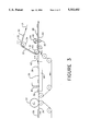
- FIG. 3 schematically depicts a system for manufacturing the FIG. 1 patch bag
- FIG. 4 schematically depicts a system for packaging bone-in food mass using the FIG. 1 patch bag.
- the thin-walled thermoplastic film forming the bag is "biaxially heat shrinkable". As used herein this means that the film has an unrestrained shrinkage of at least ten (10) percent in each of the transverse and machine directions measured at 90° C. (194° F.). Preferably, the film has an unrestrained shrinkage of at least twenty (20) percent in each direction.
- the relatively thick-walled thermoplastic film patch is "non-heat shrinkable". As used herein this means the patch has an unrestrained shrinkage below about five (5) percent in each of the transverse and machine directions measured at 90° C.
- the unrestrained shrink of the film is measured by a procedure derived from ASTM D2732 after immersion in a water bath at 90° C. for five seconds.
- Four test specimens are cut from a given sample of the film to be tested. The specimens are cut to 10 cm. in the machine direction by 10 cm. in the transverse direction. Each specimen is completely immersed for 5 seconds in a 90° C. water bath. After removal from the water bath the distance between the ends of the specimen is measured. The difference in the measured distance for the shrunken specimen and the original 10 cm. is multiplied by ten to obtain the percent of shrinkage for the specimen.
- the shrinkage for the four specimens is averaged for the MD shrinkage values of the given film sample, and the shrinkage for the four specimens is averaged for the TD shrinkage value.
- barrier or “barrier layer” as used herein in connection with the bag means a layer of a multi-layer film which acts as a physical barrier to gaseous oxygen molecules. Physically, a barrier layer material will reduce the oxygen permeability of a film (used to form the bag) to less than 70 cc per square meter in 24 hours at one atmosphere 73° F. (23° C.) and 0% relative humidity. These values should be measured in accordance with ASTM standard D-1434.
- ethylene vinyl acetate copolymer refers to a copolymer formed from ethylene and vinyl acetate monomers wherein the ethylene derived units (monomer units) in the copolymer are present in major, by weight, amounts and the vinyl acetate derived units (monomer units) in the copolymer are present in minor, by weight, amounts, generally between about 5 and 40 wt. % of the total.
- wetting tension refers to a measure of the surface energy of a film in accordance with the test described in ASTM D2578-84.
- An essential aspect of this invention is that the patch inner surface and the bag film outer surface to be bonded together are each separately exposed to high energy to impart wetting tension of at least about 38 dynes/cm to these surfaces. This may for example be accomplished by corona discharge, flame, plasma and ultraviolet treatment, and, in general, treatments which expose the EVA-polyethylene blend surfaces to energetic radiation in the presence of gas such as oxygen or nitrogen.
- Corona discharge is the preferred high energy to film surface transfer method, and preferably in the range of about 44 to 46 dynes/cm wetting tension. Higher surface energies do not appear necessary to achieve the needed strong bond between the patch and the bag.
- Bonet U.S. Pat. No. 4,120,716 directed to improvement of adherence characteristics of the surface of polyethylene by corona treatment to oxidize the polyethylene surface to promote wetting by printing inks and adhesives.
- flame surface treatment of polymeric film is the representative disclosure of Lonkowsky U.S. Pat. No. 2,767,103.
- ultra violet surface treatment of polymeric film is the representative disclosure of Wolinski U.S. Pat. No. 3,227,605.
- plasma surface treatment of polymeric film is the disclosure of Baird et al. U.S. Pat. No. 3,870,610.
- VLDPE very low density polyethylene
- ULDPE ultra low density polyethylene
- VLDPE linear low density polyethylene
- ULDPE ultra low density polyethylene
- This expression does not include ethylene alpha olefin copolymers of densities below about 0.90 g with elastomeric properties and referred to by at least one manufacturer as "ethylene alpha olefin plastomers”.
- ethylene alpha olefin plastomers may be used in the practice of this invention as a minor constituent in the patch inner or outer surface and/or the bag outer surface, as long as it does not prevent the surface from performing its intended function.
- VLDPE does not include linear low density polyethylene (LLDPE) which have densities in the range of about 0.915-0.930 gm/cm 3 .
- VLDPE comprises copolymers (including terpolymers) of ethylene with alpha-olefins, usually 1-butene, 1-hexene or 1-octene, and in some instances terpolymers, as for example of ethylene, 1-butene and 1-octene.
- alpha-olefins usually 1-butene, 1-hexene or 1-octene
- terpolymers as for example of ethylene, 1-butene and 1-octene.
- VLDPEs are capable of use in biaxially oriented films which have superior properties to comparable films with LLDPEs. These superior properties include higher shrink, higher tensile strength and greater puncture resistance.
- Suitable VLDPEs include those manufactured by Dow Chemical Company, Exxon Chemical Company and Union Carbide Corporation, and having the following physical properties in the resin form according to the manufacturers, as summarized in Table A.
- Linear low density polyethylene has densities in the range of between about 0.915 and about 0.930 g/cm 3 .
- LLDPE Linear low density polyethylene
- the linear structure and lack of long chain branching in both LLDPE and VLDPE arise from their similar polymerization mechanisms.
- the random incorporation of alpha-olefin comonomers produces sufficient short-chain branching to yield densities in the above-stated range.
- Suitable LLDPE for use in the heat shrinkable bag outer surface of this invention include Dow's Dowlex types 2045 and 2247A. Their physical properties are summarized in Table B.
- a variety of ethylene vinyl acetates may be used in the patch inner surface and the bag outer surface, and having vinyl acetate contains up to at least 20% of the copolymer total weight.
- Vinyl acetate contents in the range of 8-12 wt. % are preferred from the standpoint of processability and strength.
- lower vinyl acetate contents than this preferred range tend to produce poorer shrinkage.
- Higher VA contents tend to be excessively tacky and difficult to orient.
- lower VA contents than this preferred range tend to be stiffer and less elastic than preferred for the patch. Higher VA contents tend to be excessively tacky.
- thermoplastic film for this construction which is an oxygen barrier.
- the essential outer surface of the bag is not itself an oxygen barrier, if the latter property is needed it must be provided as a separate layer of a multilayer film, most commonly as the core layer.
- Widely used barrier materials include vinylidene chloride copolymers with various comonomers such as vinyl chloride (VC-VDC copolymer) or methyl acrylate (MA-VDC copolymer).
- the preferred barrier layer is a blend of about 85% vinylidene chloride-methyl acrylate comonomer and about 15% vinylidene chloride-vinyl chloride comonomer, as for example described in Schuetz et al. U.S. Pat. No. 4,798,251.
- Other suitable oxygen barrier materials include polyamides and ethylene vinyl alcohol.
- the most commonly used barrier-core layer multilayer film for food product-containing bags comprises at least three layers, with a heat sealable layer adhered to one side of the barrier layer and forming the inside layer of the bag converted from the film.
- heat sealable material refers to a thermoplastic material which will seal to itself or another material when subjected to elevated temperature and/or pressure. EVA is a well-known heat sealable material. Even though heat sealable materials are preferred as the inner layer of the bag-forming thermoplastic material, bags can be sealed after evacuation by mechanical clipping, so a heat sealable material is not essential.
- an impact-abrasion resistant EVA-polyethylene blend is adhered to the opposite side of the barrier core layer to form the bag outer layer.
- Polyethylenes such as VLDPE and LLDPE have higher impact-abrasion resistance than EVA. This property is desirable for both the patch inner surface and the bag outer surface.
- the polyethylenes do not provide the high heat shrinkability property needed in the bag, but this is a characteristic of ethylene vinyl acetate.
- VLDPE provides substantially higher heat shrink than LLDPE.
- the EVA-VLDPE blend provides both the high abrasion and impact resistance as well as the high heat shrink property needed by the bag outer surface.
- the bag outer surface comprises a blend of about 15-65% EVA and 85-65% VLDPE.
- the physical properties of the patch inner surface must be at least similar to those of the bag outer surface.
- this may be achieved by using EVA or EVA-VLDPE blends as the patch inner surface, and certain EVA types, EVA-VLDPE blends, and EVA-LLDPE blends as the bag outer surface.
- both surfaces are blends of EVA and VLDPE; most preferably they are both about 15-65% EVA and about 85-35% VLDPE.
- the patch inner surface and the bag outer surface are unexpectedly bonded to each other solely by their respective high surface energies.
- the EVA content of the bag outer surface should preferably be at least about 15 wt. % because EVA provides relatively high shrink, but should not exceed about 65 wt. % because of the relatively low impact-abrasion resistance of EVA.
- the VLDPE content of the bag outer surface should preferably be at least about 35 wt. % because VLDPE provides relatively high impact-abrasion resistance, but preferably should not exceed 85 wt. % because VLDPE has lower heat shrink than EVA.
- the patch inner surface composition is preferably in the same EVA and VLDPE blend range to be chemically similar and provide high bond strength between the high energy surfaces.
- the ethylene vinyl acetate contents in the patch inner surface and the bag outer surface are most preferably within about 25 weight % of each other because similar chemistry optimizes the adhesion between the two surfaces.
- the very low density polyethylene contents of the patch inner surface and the bag outer surface are most preferably within about 25 weight % of each other for the same reason as discussed in connection with the EVA contents, i.e. similar chemistry optimizes adhesion.
- the inner and outer layers of the preferred three layer film for the bag both comprise blends of VLDPE and EVA, as for example described in the aforementioned Lustig et al. U.S. Pat. No. 4,863,769.
- the film comprising the bag is provided either as a flat sheet or as a tube, most commonly the latter.
- This primary and relatively thick film may be biaxially oriented by the well-known tentering process, but most commonly this is done by the trapped bubble or double bubble technique as for example described in Pahlke U.S. Pat. No. 3,456,044. In this technique an extruded primary tube leaving the tubular extrusion die is cooled, collapsed and then preferably oriented by reheating and reinflating to form a secondary bubble.
- the film is preferably biaxially oriented wherein transverse (TD) orientation is accomplished by inflation to radially expand the heated film.
- Machine direction (MD) orientation is preferably accomplished with the use of nip rolls rotating at different speeds to pull or draw the film tube in the machine direction.
- the stretch ratio in the biaxial orientation to form the bag material is preferably sufficient to provide a film with total thickness of between about 1.5 and 3.5 mils.
- the MD stretch ratio is typically 3-5 and the TD stretch ratio is also typically 3-5.
- An overall stretch ratio (MD stretch multiplied by TD stretch) of about 9-25% is suitable.
- the preferred method for forming the preferred multilayer bag film is coextrusion of the primary tube, as for example described in Lustig et al. U.S. Pat. No. 4,714,638.
- the coextruded primary tube is then biaxially oriented in the manner broadly described in the aforementioned Pahlke Patent.
- the multilayer film may be formed by extruding a substrate layer and then adding the remaining layers to the substrate by coating lamination, as for example described in Brax et al. U.S. Pat. No. 3,741,253. If two additional layers are to be added to the substrate layer, this may be done sequentially or the two layers may be coextruded and then added to the substrate layer by coating lamination.
- the entire bag film is preferred to broaden the heat sealing range of the inner layer and also enhance the toughness properties of the inner and outer layers.
- This is preferably done by irradiation with an election beam at dosage level of at least about 2 megarads (MR) and preferably in the range of 3-5 MR, although higher dosages may be employed. Irradiation may be done on the primary tube or after biaxial orientation. The latter, called post-irradiation, is preferred and described in Lustig et al. U.S. Pat. No. 4,737,391.
- An advantage of post-irradiation is that a relatively thin film is treated instead of the relatively thick primary tube, thereby reducing the power requirement for a given treatment level.
- a possible advantage of preorientation irradiation is that if the practioner is using a barrier layer material which tends to discolor on irradiation as for example vinylidene chloride-vinyl chloride copolymer, this problem may be avoided by irradiating only a substrate layer as described in the aforementioned Brax et al. patent.
- cross linking may be achieved by addition of a cross linking enhancer to one or more of the layers, as for example described in Evert et al. U.S. Pat. No. 5,055,328.
- the most commonly used cross linking enhancers are organic peroxides such as trimethylpropane and trimethylacrylate.
- barrier type multilayer films are preferred for bag fabrication, it should be recognized that for some end uses a barrier material may not be required, as for example poultry type bone-in food masses.
- the bag may be monolayer film comprising an EVA-polyethylene blend.
- the patch is a blown, non heat shrinkable film which can be either a monolayer or a multilayer construction.
- the patch inner surface must be capable of initially bonding to the bag outer surface solely by high energy treatment of both surfaces and pressure contact. Moreover, the bond must be strong enough to resist delamination when the food-containing bag with a non-heat shrinkable patch is heat shrunk.
- the patch outer surface must have high puncture strength and resistance to abrasion. All of these properties may be realized in 100% EVA or 100% VLDPE monolayer patches or certain types of EVA-VLDPE blends as a monolayer.
- the blend preferably comprises 15-65% EVA and 85-35% VLDPE, with a 50% EVA-50% VLDPE blend most preferred.
- the patch may comprise at least two layers: an inner layer with an inner surface suitable for high surface energy lamination to the bag outer surface, and an outer layer with an outer surface providing high external abrasion resistance and puncture resistance. If the patch inner layer is formed of material having relatively low puncture resistance as for example EVA, the patch outer layer preferably also provides puncture protection against sharp edges of the food body. For this reason, the preferred multilayer patch with a 100% EVA inner layer has an outer layer comprising 15-25% EVA and 75-85% VLDPE. The high VLDPE content provides additional protection against internal puncture.
- the patch may be irradiated, and preferably at dosage of at least about 5 MR.
- FIG. 1 is a schematic drawing of a plan view of a patch bag 10 fabricated according to this invention and comprising a biaxially oriented heat shrinkable relatively thin-walled thermoplastic film bag 11 and non-heat shrinkable relatively thick-walled thermoplastic film patch 12 bonded to an outer surface of the bag.
- Patch 12 preferably covers less than the entire surface area of at least one side of bag 11. Both the patch 12 inner surface and at least the bag outer surface portion 13 coextensive with the patch inner surface have been exposed to high energy as for example corona discharge, so as to be characterized by high surface energy of at least about 38 dynes/cm as the sole bonding means therebetween.
- This surface energy is sufficient so that when the patch bag 10 is filled with bone-in food mass as for example beef loin subprimal cuts, evacuated, sealed and heat shrunk around the bone-in food mass, the bag outer surface portion 13 bonded to the patch shrinks to a lesser extent than the remainder 14 of the bag, but the patch 12 does not delaminate from the bag 11.
- Bag 11 generally comprises two sides having interior and exterior faces, a closed end 15 and an opening 16 into the interior of the bag opposite end which is often referred to as the mouth of the bag.
- FIG. 2 is a schematic drawing of a food package 20 prepared according to this invention, comprising a heat shrunk and relatively thin-walled thermoplastic film bag 21 containing bone-in food mass 22 in an evacuated and sealed space within the bag, such that the mass 22 outer surface with protruding bones 23 is in direct supporting relationship with the collapsed bag inside surface.
- the bag mouth is sealed, preferably by a heat bond 24 between the bag inner surfaces.
- a non heat shrinkable and relatively thick-walled thermoplastic film patch 25 is provided with the patch inner surface positioned over any protruding bones 23.
- the non heat shrinkable patch inner surface and the heat shrunk patch outer surface are bonded together solely by contacting each of these surfaces having high surface energy of at least about 38 dynes/cm.
- the strength of the existing patch-bag bond increases and the bag portion adhered to the patch shrinks to a lesser extent than the nonpatched remainder 26 of the bag. This is because of the extremely strong high surface energy patch-bag bond which restrains shrinkage of the covered bag portion. But because of this extremely strong patch-bag bond the patch does not delaminate from the bag.
- FIG. 3 is a schematic drawing of a preferred system for manufacturing the FIG. 1 patch bag, in which the flattened tubular film 30 having high energy on its exterior surface and ultimately used to fabricate the bags (hereinafter “bag film”) is introduced on upwardly inclined roll 31. It passes beneath negative static generator 32 which imparts a negative change of about 15 kv to the high energy surface. The purpose of this charge is to insure a static cling with the positively charged patch surface (hereinafter discussed) as the two mate at the nip rollers.
- the negatively charged high surface energy bag film 33 is downwardly directed by idler roll 34, still on roll 31.
- patch stock with high energy top surface 35 is introduced on horizontal conveyor belt 36 and passes beneath rotary cutter 37 where the stock is transversely severed into longitudinally spaced patches 38, and transferred to horizontal support roll 39 for movement by air fingers.
- the distance between adjacent patches and the conveying speeds of the patch and bag film are arranged so that the two components are mated in the desired manner.
- Patches 38 are horizontally moved on support roll 39 over vacuum chamber 40 where the applied vacuum maintains the patches in the desired spaced positions.
- the patches initially travel beneath static eliminator 41 and then beneath positive static generator 42 which imparts a positive charge of about 15 kv to the patch high energy to surface.
- Bag film 33 and patches 38 are mated on conveyor 39 under slight pressure between soft rubber marriage roller 43 and a support roller.
- the composite patch-film is then fed through the nip roller system comprising hard rubber upper roller 44 and steel lower roller 45 to form an initial bond. Satisfactory initial bond laminations have been produced with pressures of about 40 psi and about 2500 psi on the patch-bag film composite, and probably lower or higher pressures would be satisfactory. Loading pressures of 40100 100 psi. are preferred.
- the preferred temperature for nip rolls 44 and 45 using VLDPE-EVA blends for both bonding surfaces is about 100°-110° F. The rolls may be heated by electric coils 46 to maintain this temperature level in cold weather.
- the resulting initially bonded bag film-spaced patch article 48 is discharged from the nip rolls 45-46 onto conveyor 49 for further processing as for example described in connection with FIG. 4.
- FIG. 4 is a schematic drawing of a system for manufacturing the food package of this invention from the initially bonded bag tube film-spaced patch article 48 of FIG. 3.
- This article may for example be stored in roll form, converted by the manufacturer into patch bags and sold to the food processor for use in forming the food packages of this invention.
- the entire sequence may be performed at one location in an "in-line" system as depicted in this FIG. 4.
- the initially bonded bag tube film-spaced patch article 48 in lay-flat form is moved by conveyor 49 to sealing and bag forming station 50.
- the latter comprises upper and lower sealing jaws 51 and 52, and bag severing means 53.
- the combined action of these elements may be arranged, as is well known in the art, such that the leading edge of article 48 is open so as to define the mouth or open end of the bag being formed.
- Jaws 51 and 52 cooperate to make a transverse heat seal to bond the opposite end of a same bag, and severing means 53 separates that patch bag 54 from the open end of the next successive bag. It will be understood that many other methods of bag formation from a tube are well known to those skilled in the art, and any of these may be used to convert the initially bonded bag tube--spaced patch article into the patch bag of this invention.
- the patch bag 54 is next moved to bag opening and filling station 55 which may for example include gas inflation means (not illustrated).
- Bone-in food mass 56 is introduced in opened patch bag 57 and positioned so that any protruding bones are located beneath the patch.
- the open patch bag-containing bone-in food mass 58 is moved to evacuation station 59 where the bag interior is evacuated so the bone-in food mass outer surface directly supports the collapsed bag inside surface.
- the evacuated but open mouthed bone-in food mass-containing patch bag 60 is then sealed either by clipping or preferably by a transverse heat seal across the bag mouth, at heat sealing station 61.
- Suitable means for accomplishing the evacuating and sealing steps are for example disclosed in Kuehne U.S. Pat. No. 4,534,984 and Kupcikevicius U.S. Pat. No. 5,062,252, both incorporated herein by reference.
- the evacuated and sealed bone-in food mass-containing patch bag is passed through shrink tunnel 62 where the bag is heat shrunk as for example by upward and downward sprays 63 of hot water at for example 195° F.
- the bag is heat shrunk against the bone-in food mass outer surface and the bond between the high surface energy treated bag outer surface and patch inside surface is simultaneously increased is a second bond enhancement step.
- the bag portion adhered to the patch shrinks to a lesser extent than the remainder of the bag, but this enhanced strength bond is sufficient to prevent delamination of the non-heat shrinkable patch from the heat shrunk bag.
- the resulting food package 64 discharged from hot shrink tunnel 62 is cooled to slightly above freezing temperature such as 35° F. by means not illustrated, and comprises the FIG. 2 food package of this invention.
- E-Z GUARD® patch bag For comparison with the prior art, a series of shaker tests were performed using as the control, a commercial patch bag product sold by Viskase Corporation as E-Z GUARD® patch bag. This product was commercially successful in terms of meeting food processor requirements for packaging and transporting bone-in beef.
- This commercially employed product had a collapsed bubble-type heat shrinkable multilayer film patch comprising an ethylene methyl acrylate (EMA) core layer and inner and outer layers each comprising about 40% EVA, 40% LLDPE and 20% VLDPE.
- EMA ethylene methyl acrylate
- the patch was about 5 mils thick, irradiated to about 10 MR and bonded to the bag outer layer by a water-based adhesive.
- the bag was Viskase Corporations's commercially employed PERFLEX type comprising a heat shrinkable three layer film with an oxygen barrier-core layer comprising a blend of 85% MA-VDC copolymer and 15% VC-VDC copolymer.
- the inner and outer layers were 75% VLDPE (Union Carbide type 1192) and 25% EVA (Union Carbide type 6833).
- the bag thickness was about 2.25 mil.
- the bag was heat shrinkable to the extent of about 30-35% in both the machine and transverse directions.
- the patch was heat shrinkable to the extent of about 25-30% in both directions.
- the experimental patches were adhered to the bag-forming tubular film by water-based or organic solvent based adhesion.
- the patch material was extruded in tubular form, and longitudinally slit to form a flat sheet which was corona treated to impart high wetting tension of about 42 dynes/cm on one side.
- the aforedescribed bag film was also extruded in tubular form and its outer surface corona treated to impart high wetting tension of about 42 dynes/cm.
- Nonadhesive slip sheets were applied to the patch (at desired longitudinal spacing) and bag film high energy surfaces to prevent blocking, and each was wrapped in roll form.
- Corona treatment was performed by a covered roll multiple electrode treater using apparatus identified by the manufacturer, Pillar Company of Hartland, WI as Model AB 1326-1A. Corona treatment may also be done with bare roll type apparatus.
- each patch was about 213/4 inches long ⁇ about 163/4 inches wide, and was centered on the 17 inch wide bag outer surface with about 83/4 inches spacing between the ends of adjacent patches.
- the patch-bag laminate was stored at least 12 hours under roll pressure to allow the initial bonding of the two high energy surfaces. Initially this storage period was 2-3 days (Examples 1 and 2), and then the patch-tubular substrate laminate was converted into patch bags. For Examples 3-8, the tubular substrate bag film was heated to 105°-115° F. after corona treatment and then immediately intertwined with the patch by the rewinder. In this manner, the patch-tubular substrate bag laminate was rolled up with internal heat which accelerated initial bonding between the two high energy surfaces. When this was done, the initial bond was sufficiently strong after 12 hours storage for conversion into bags. In effect, this 12 hour storage provided curing time for the initial bonding to occur.
- the patch-bag bond was strengthened when the bone-in food containing package was heat shrunk.
- this packaging was done about 14 days after the initial patch-bag film bonding.
- a standard type and size of sub primal beef rib cut from a standard primal beef rib cut was placed in a variety of patch bags, evacuated and heat sealed.
- the heat sealed packages were heat shrunk by external contact with hot water sprays, so that the heated patch bag inner surface shrunk over the outer surface of the sub primal beef rib.
- the heat shrunk packages were placed in open cardboard boxes (three side-by-side packages per box) of a size commonly used in the beef packaging industry, the relative sizes of the packages and the box being such that the packages loosely fit against each other and would slide when the box was mechanically shaken.
- the packages were examined to insure that no bones protruded from unpatched areas of the packages.
- each cut was placed in each type patch bag, and each type package was placed in different positions in the box.
- the data from these shaker tests was organized in terms of survival time without failure, i.e. breakage due to external abrasion or puncture of the patch and the patch-covered bag irrespective of the cause.
- the arithmetic average survival time without failure was calculated for each type of patch bag (in minutes) as well as the standard deviation (in minutes) from the average survival time.
- the actual total survival time for all tested bags of a particular type was determined by addition, and calculated as a percentage of maximum possible survival time based on an arbitrary total survival time of 135 minutes.
- the abrasion performances of the patch bag types used in a particular experiment were then compared on a qualitative rather then quantitative basis. That is, the survival time information may be compared to determine if two types of patch bags provide similar or substantially different abrasion performance.
- NAMP National Association of Meat Purveyors
- the chine bone is removed by a cut which exposes lean meat between the feather bones and the vertebrae, leaving the feather bones attached.
- the blade bone and related cartilage is removed.
- the target weight for No. 107 beef rib for these experiments was 22 lbs. and each rib was about 14-15 inches long.
- the aforedescribed film used to fabricate the bags was prepared by coextrusion and biaxially oriented by the double or trapped bubble technique, the proportions of the oriented film layer thicknesses being 27% (outer)/10% (core)/63% (inner).
- the biaxially oriented film was post irradiated at dosage of about 4 MR.
- the sub primal beef rib cuts were first conditioned by placement in non test patch bags and vibrated/oscillated for 2 hours on the shaker table to round off the sharpest protruding bones. This was done to insure that at least most of the test patch bags would survive the initial period of the shaker abrasion test, and meaningful experimental information could be developed.
- the beef rib sub primal cut-containing patch bag was evacuated to an absolute pressure on the order of 60 mm. Hg. and impulse heat sealed across the top in a Super Vac® machine manufactured by Smith Equipment Company, Clifton, N.J.
- the evacuated packages were then processed through a commercial-type shrink tunnel wherein the packages were moved on a conveyer belt through downward and upward hot water sprays at 195° F. for a contact time of about 11/2 seconds.
- the heat shrunk packages were chilled for at least 12 hours at 35° F.
- the chilled heat shrunk packages were externally dried and placed side-by-side lengthwise resting on the feather bones in open cardboard boxes of about 20.5 inches ⁇ 17.25 inches ⁇ 10 inches with three packages per box. To obtain representative loading configuration alternate boxes were loaded L-R-L and R-L-R in terms of left side cuts and right side cuts.
- the boxes were placed on a shaker table manufactured by Gaynes Engineering Company, Chicago, Ill.
- the shaker motion was a rolling circle of about 1 inch diameter, at a rate of 100 cycles per minute.
- sample 1 patch was irradiated to 10 MR and adhered to the bag by a commercially available water based acrylic adhesive, Northwest Adhesive Company's Product, NW No. 707.
- the adhesive was applied to the patch material, and the article was placed in an oven to evaporate excess moisture to a water content of about 8% of the adhesive weight.
- a paper slip sheet was placed over the adhesive-containing patch surface and the patches were cut to size.
- the patch was joined to the tubular bag film outer surface under light pressure of about 2 psi, the patch-film composite rolled, and the roll was stored for about 3 days. During this period the roll compression on the patch-film increased to about 15 psi.
- Example 1 demonstrated that a non-heat shrinkable LDPE blown film patch was not satisfactory when adhered to the bag by a conventional water-based adhesive.
- Example 3 The purpose of this experiment was to qualitatively compare the abrasion resistance of a 10 MR irradiated 50% EVA (Union Carbide type 6833) - 50% VLDPE (Dow's type XU 61520.01) blown film non-heat shrinkable 5 mil thick patch on a 17 inch flat width bag (sample 3) with that of the aforementioned E-Z GUARD patch bag (biaxially oriented patch adhered to the same type of commercially used bag) as sample 4.
- the adhesive and patch-bag film bonding procedure for sample 3 was the same as described in Example 1.
- Table D The results of these tests are summarized in Table D. The latter shows that the experimental bags were markedly inferior to the commercial control bags, and would not satisfy commercial standards. Accordingly, Example 2 demonstrated a 50% EVA - 50% VLDPE blown film patch was not satisfactory when adhered to the bag by conventional water-based adhesive.
- the purpose of this experiment was to test the effectiveness of an organic solvent-based adhesive as the bonding agent for a 100% LLDPE (type Dowlex 2045 manufactured by Dow, density 0.920 g/cm 3 ) nonirradiated blown film patch having 0% shrinkability to the outer surface of the aforedescribed commercially employed multilayer oxygen barrier PERFLEX type heat shrinkable film with a 75% VLDPE--25% EVA outer layer.
- the organic solvent-based adhesive was AROSET® type 1085-Z-85 pressure sensitive adhesive described by its manufacturer, Ashland Chemical Company, as a thermosetting acrylic solution polymer. Because of its organic content, the manufacturer recommends that after application, the adhesive-containing body be heated to at least 250° F. to maximize effectiveness of the adhesive, volatilize the organic residue and remove odor traces which are characteristic of organics.
- the adhesive was applied to both the inner surface of the 4 mil thick patch of blown film comprising 100% LLDPE having a Vicat softening point of about 212° F., and the outer surface of the aforedescribed three layer 3.25 mil thick film material.
- the patch-film combination was bonded at room temperature under slight contact pressure, e.g. 10 psi.
- a higher curing temperature was not used because the softening point of the LLDPE in the patch and the EVA and VLDPE film outer layer blends were all below 250° F. It was noted that noxious fumes were present even at the lower as-practiced room drying temperature, so that a special venting and exhaust system would be needed for commercial practice at this less than optimum temperature level.
- test bags as sample 5 were loaded with No. 107 beef ribs, evacuated, sealed and immersed in hot water, then subjected to abrasion testing along with heat shrinkable control patch bag sample 6 (identical to heat shrinkable patch bag sample 4).
- Table D The latter shows that the experimental bags were markedly inferior to the commercial control bags and would not satisfy commercial standards.
- Example 3 demonstrated that organic solvent-based adhesives are not suitable for bonding a non-heat shrinkable LLDPE-containing blown film patch to a heat shrinkable bag having a VLDPE-EVA outer surface.
- the purpose of this experiment was to qualitatively demonstrate the effect of shrink tunnel heating on patch-to-bag bonding by corona treatment.
- the blown non-heat . shrinkable patch film was 5 mils thick, and comprised a 50% VLDPE (Dow type XU61520.01)--50% EVA (Union Carbide type 6833) adhered to a 3.25 mil thick three layer heat shrinkable barrier film having an outer layer comprising 75% VLDPE (Dow type 4001)--25% EVA (Union Carbide type 6833).
- the patch inner surface and the bag film outer surface were separately corona treated so as to provide surface energy of at least about 42 dynes/cm 2 .
- the patch bags were prepared and filled with No. 107 beef ribs, evacuated and sealed. Prior to hot water shrinking, the patches were visually inspected and found to be firmly bonded to the bag outside surface. However, with a moderate effort the patch could be pulled off the bag. After heat shrinking there was no visual evidence of patch delamination and it was noticeably more difficult to manually pull the patch away from the bag.
- the purpose of this experiment was to quantitatively demonstrate the effect of shrink tunnel heating on non-heat shrinkable patch-to-heat shrinkable bag bonding by corona treatment, using a peel strength test.
- Sections of the same patch bag composite used in Example 3A were used in the experiment, one section being heat shrunk by a hot water immersion procedure very similar to that described in ASTM D-2732 to simulate typical shrink tunnel operating conditions.
- the only significant differences from the ASTM procedure were that the patch bag sample was immersed in 90° C. water for five seconds and air dried.
- the peel strength tests were performed on an Instron Table Model Tensile Testing Machine manufactured by Instron Corporation, Canton, Mass. and equipped with a COF stationary (horizontal) plane, using a procedure derived from ASTM-D 903.
- the samples were cut 8 inches long in the machine direction (MD) across the sheet, and 1 inch long in the transverse direction (TD).
- a corner of the sample was dipped in xylene and the patch partially separated by manually slowly pulling apart at a 180° angle starting at the corner, to separate 1-2 inches in the MD and across the TD.
- the partially separated patch end was connected by a 3/4 inch long standard office-equipment type binder clip through an 8 lb. test monofilament fishing line and secured to the longitudinal stationary plane by a jaw holder.
- the crosshead was set to pull at 1 inch/minute and the test was run. Maximum, minimum and average peaks in force were read from the chart, and the average force in grams to separate the patch from the bag was calculated from the average peak height.
- Patch-bag adhesion prior to the shrinking was 180 grams/inch.
- Patch-bag adhesion after shrinking was 365 grams/inch, and failure was due to delamination of the multilayer bag film, not the bag-patch bond.
- the patch inner surface and the bag outer surface should have high surface energy of at least about 38 dynes/cm wetting tension as the sole bonding means therebetween.
- the bond strength increases with increasing surface energy, but there is no need to provide a bag-patch bond which is stronger than the lamination strength of a multilayer bag film.
- the preferred energy levels of the patch inner surface and bag outer surface is 44 to 46 dynes/cm wetting tension.
- Sample 7 used a 50% VLDPE (Dow type XU61520.01) - 50% EVA (Union Carbide type 6833) 5 mil thick blown film patch irradiated to 10 MR and bonded to the aforedescribed 3.25 mil thick bag with a 75% VLDPE-25% EVA outer layer solely by high surface energy from corona treatment.
- Sample 8 was the aforedescribed commercially employed heat shrinkable patch bag (E-Z GUARD patch bag) which was identical to samples 4 and 6.
- Table D shows that the invention package is equivalent to the heat shrinkable patch type bag commercial package in terms of abrasion resistance.
- sample 9 included a 75% VLDPE (Dow type XU61520.01 with 0.9 MI) - 25% EVA (Union Carbide type 6833 with 0.25 MI) 5 mil thick patch irradiated to 10 MR and bonded to the aforedescribed 3.25 mil thick bag with the 75% VLDPE-25% EVA outer layer, and sample 10 was identical to previously described sample 7.
- the only difference between samples 9 and 10 was the VLDPE-EVA blend in the blown film patch.
- Sample 11 used the previously described E-Z GUARD control heat shrinkable patch type patch bag which was identical to samples 4, 6 and 8.
- a preferred patch material for practicing this invention is a monolayer comprising between about 25-50% ethylene vinyl acetate and about 75%-50% very low density polyethylene.
- Sample 12 used a 3.25 mil thick bag.
- Sample 13 was the control and used the same type heat shrinkable patch bag as in samples 4, 6 and 8.
- Table D The results of the abrasion tests are summarized in Table D, and demonstrate that the LDPE blown film corona laminated patch bag is substantially inferior to the control heat shrinkable patch bag, so would not be commercially acceptable.
- Sample 14 used a 10 MR irradiated 50% EVA (Exxon's type D318.92, MI 2.2) - 50% VLDPE (Exxon's Exact type 3010B, MI 2.2) blown film 5 mils thick patch with 0% heat shrink and a 3.25 mil thick bag.
- the latter's outer surface comprised the aforedescribed 75% Union Carbide type 1192 VLDPE (0.19 MI)--25% EVA (0.25 MI).
- Sample 15 used the previously described commercially employed heat shrinkable E-Z GUARD patch bag.
- EVA Viskase PERFLEX as a control, a 100% EVA (Union Carbide type 6833 with 10% vinyl acetate), a TUF SEAL 90® bag sold by American National Can Company and believed to have a 100% EVA outer surface, and a TUF SEAL II bag sold by American National Can Company and believed to have an EVA-LLDPE blend outer surface.
- Eight (8) different patch inner surface compositions were used, including the preferred sample 14 (Example 8) 50% VLDPE (MI 2.2) - 50% EVA (MI 2.2).
- the combination of this patch material and the Viskase commercially employed PERFLEX bag comprising 75% VLDPE - 25% EVA is identical to the sample 14 patch-bag combination, and is the control for the experiments.
- the patch materials were 5 mils thick and the bag materials were 2.25 mils thick.
- the terms "patch” and "bag” are used for consistency with the terminology in this specification, but unlike the preceding examples, the actual samples used in these experiments were in single sheet form. However, these samples were corona treated to impart high wetting tension of about 42 dynes/cm, and laminated in exactly the same manner as the previously described patch bags.
- the patch materials were irradiated at 10 MR.
- the PERFLEX bag materials irradiated at 3 MR (EVA type) and 4 MR (EVA/VLDPE type).
- the TUF SEAL 90 and II bags are believed to have been irradiated at about 4 MR.
- Lamination strength was measured by the procedure derived from ASTM-D903 and described in Example 4B, using an Instron Table Model Testing Machine to determine the force (in grams) required to pull the patch bag films apart. It should be noted however, that whereas the Example 4B samples were immersed in hot water to simulate shrink tunnel treatment prior to the peel test, in this instance the samples were not heat shrunk. The results of the experiments are summarized in Table E.
- Table E peel strength data is not a quantitative measure of the corona treated patch-to-bag lamination strength in commercial practice. This is because the lamination strength is substantially increased by shrink tunnel heating the food-containing package, as qualitatively and quantitatively demonstrated by Examples 4A and 4B respectively. However, to be functional, there must be sufficient patch-to-bag lamination strength from the individual components' corona treatment and pressure contact so that the composite may be processed through the several steps of bag formation, storage, filling with food, and movement to the shrink tunnel.
- Table E shows that only patches with inner surfaces comprising EVA or EVA and VLDPE blends provided corona lamination strength. That is, the 100% LLDPE, 50% EVA/50% LLDPE, 50% EVA/50% plastomer and 50% EVA/50% HDPE patch-to-bag combinations had no corona lamination strength. Since they could not be processed in this loose form, they are unsuitable for practice of the invention.
- the EVA/VLDPE bag outer surface tests demonstrate that from the corona lamination standpoint alone, a 100% EVA patch and 25 to 75% EVA--75 to 25% VLDPE patches were all suitable, with the 25%-75% VLDPE patch providing the highest corona lamination strength.
- Table E shows that the PERFLEX 100% EVA (Union Carbide's 6833, 10% VA and 0.25 MI) is not a suitable bag outer surface for practicing this invention because there was no peel strength with even the EVA-VLDPE blend patches, yet the presumably EVA outer surface of TUF SEAL 90 demonstrated at least equivalent peel strengths to the PERFLEX EVA-VLDPE blend bag outer surface for 100% EVA and EVA-VLDPE blend patches. This anomaly is not understood, but it appears that certain EVA bag outer surfaces are suitable for practicing this invention.
- Table E shows that the EVA-LLDPE blend outer surface of TUF SEAL II bags have somewhat lower corona lamination strengths than PERFLEX EVA/VLDPE or TUF SEAL 90 bags. However, these levels are considered adequate for structural integrity of the composite during the processing steps up to the shrink tunnel, so the EVA-LLDPE blend represents an embodiment of the bag outer layer aspect of the invention.
- bag heat shrink Another consideration for the practioner is selecting a suitable bag composition for practicing this invention is the bag heat shrink. From this standpoint EVA is superior to both VLDPE and LLDPE. However, under equivalent conditions VLDPE provides substantially higher heat shrink than LLDPE, and the same is true for EVA-VLDPE blends compared to EVA-LLDPE. These relationships are quantitatively demonstrated in Lustig et al., U.S. Pat. No. 4,863,769, incorporated herein by reference. For these reasons EVA-VLDPE blends are preferred to EVA-LLDPE blends as the bag outer surface.
- the apparatus included a power-driven rotatable (70 rpm) flat surface on which the specimen was mounted, and two overhead arms with freely rotatable wheels (about 1/2 inch wide) mounted on the arm lower ends. A one kgm. weight was attached to each arm. The wheel outer surfaces were coated with abrasive material (in this instance Taber's type CS-17).
- the experimental procedure was to cut 41/2 inch by 41/2 inch samples (four for each composition), mount the sample on a cardboard backing, weigh and secure the mounted sample to the apparatus rotatable flat surface. The latter was rotated 500 cycles and specimen material was removed from the outer surface by abrasive contact with the rotating wheels. The abraded mounted sample was reweighed. Lower weight loss values (measured in mg.) generally indicate better abrasion resistance. The results of these tests are summarized in Table F.
- the patch after removal from the heat shrunk bag, the patch had more MD shrink (4% vs. 0.9%) although not at the heat shrinkable level). This is believed due to annealing and stretching which occurs during the corona bonding process.
- the strong bond to the patch substantially restrains and reduces heat shrink in the bag portion bonded to the patch. More particularly, the patch bag MD heat shrinkage is about one-half that of the bag, and the patch bag TD heat shrinkage is only about one-third that of the bag.
- the bone-in meat cuts were NAMP's No. 174 B beef loin, short loin, short-cut. This is the anterior portion of a beef loin, and separated from the sirloin by a straight cut, perpendicular to the to the split surface of the lumbar vertebrae, through a joint immediately anterior to the hip bone, leaving no part of the hip bone and related cartilage in the short loin.
- the flank was removed by a straight cut from a point on the rib end which is not more than (inch 25 mm) from the outer tip of the loin eye muscle through a point on the sirloin end which is not more than 1 inch (25 mm) from the outer tip of the loin eye muscle.
- the food processor placed wax impregnated cloth over and along the length of the chine of each beef short loin for additional protection (the usual practice) and then pulled the patch bag over the wax impregnated cloth-covered bone-in meat.
- the processing plant evacuated each bag and heat sealed the open end to form a bone-in food containing package with the protruding bones covered by the external patch.
- the evacuated packages were then passed through a commercial heat shrink tunnel for contact with hot water sprays.
- the heat shrunk product packages were visually inspected at the processing plant for possible leakage and if the package's vacuum integrity appeared questionable, the bone-in meat was repackaged in another patch bag before shipment.
- these inner layers are EVA preferably having 28 wt. % vinyl acetate, and the outer layers comprise 87% LLDPE, 10% EVA having 9 wt. % vinyl acetate, and 3% pigments and additives to aid extrusion.
- the '403 Patent discloses that this heat shrinkable patch was irradiated to about 7 MR and bonded by an adhesive to the outer surface of a bag formed of multilayer heat shrinkable film including a vinylidene chloride copolymer type core barrier layer. The outer layer of this bag appears to be 100% EVA.
- the Cryovac bag was about 2.3 mils thick and the patch was about 5 mils thick. Since the small dimensions of the product packages were about the same as the unpackaged beef short loins the packages were able to slide in the carton and abrade against each other as well as against the carton walls.
- the patch bag embodiment of this invention used in this test series was identical to sample 14 described in Example 8, including a 5 mil thick non-heat shrinkable blown film patch comprising a blend of 50 wt. % VLDPE (0.9 MI) and 50 wt. % EVA (0.9 MI), solely adhered to the bag outer surface by high surface energy from corona treatment.
- the inventive patch bags were compared with the aforedescribed commercially employed Cryovac BONE-GUARD heat shrinkable patch type of patch bag, both 17 inches wide ⁇ 30 long in the flat condition.
- the invention embodiment used in this second series was identical to that used in the first test series except that the EVA and VLDPE used as the blend for the blown film patch were each the 2.2 melt index types (instead of the 0.9 MI types used in the first test series) as also used in sample 14 of Example 8.
- the product packages (of about the same size as the first test series product packages) were placed two on the bottom and one on top in a covered cardboard box of about the same size as used in the first test series (three packages per box). Accordingly, the product packages were able to slide in the boxes during transit and abrade against each other and the box walls.
- the boxes were loaded in a truck for direct highway shipment to the supermarket distribution center. As in the first test, the loaded boxes were stacked five deep in the truck.
- the sample 16, 17, 19, 20 and 22 patches were the same 50% EVA (Exxon's type LD318.92, MI 2.2)--50% VLDPE (Exxon's type 3010B, M 2.2) blown film described in Example 8.
- the sample 16, 17, 19, 20 and 22 bags were the aforedescribed three layer PERFLEX type wherein the outer layer comprised 75% VLDPE--25% EVA. In samples 16, 19 and 20 this layer was 0.6 mil thick, in sample 17 it was 0.9 mil thick and in sample 22 it was 0.7 mil thick.
- test bags were loaded with No. 107 beef ribs, evacuated, sealed and immersed in hot water, then subjected to abrasion testing on the previously described shaker table, following the same procedure as the tests summarized in Table D. The results of these tests are summarized in Table J.
- Table J shows that in the first test series the abrasion resistance of the 2.25 mil bag invention embodiment sample 16 was similar to the prior art 2.3 mil bag of the competitor's commercially used patch bag sample 18 (control). In the second test series the abrasion resistance of the 2.25 mil bag invention embodiment sample 20 was about the same as the prior art control patch bag sample 21 having the same bag thickness. It is concluded from the foregoing that even based on the same bag thickness, the patch bag of this invention has similar abrasion resistance to the commonly employed patch bag in the food packaging industry.
- the second series was essentially a repetition of the first series with all invention embodiments employing 3.25 mil thick heat shrinkable bags.
- Sample 27 patch was irradiated at 10 MR
- sample 28 patch was identical to sample 27 except that it included 2,000 ppm SiO 2 antiblocking agent
- the sample 29 patch was identical to sample 28 except the patch was not irradiated.
- both invention embodiments employed 2.25 mil thick bags; sample 31 patch was irradiated at 10 MR whereas the sample 32 patch was not irradiated.
- test procedure was the same as in the previously described shaker table examples, and the invention embodiment bags were the aforedescribed three layer PERFLEX type wherein the outer layer comprised 75% VLDPE--25% EVA as detailed in Example 8.
- the invention embodiment patches were the same 50% EVA--50% VLDPE type also described in Example 8.
- test bags were loaded with No. 107 beef ribs and processed in the same manner as the examples summarized in Table D.
- the shaker table test results are summarized in Table K.
- Table K shows that with respect to the first test series 3.25 mil thick patch bags with 2000 ppm SiO 2 antiblock in the patch, the abrasion resistance of the nonirradiated patch sample 25 was at least equivalent to the 10 MR irradiated patch sample 24.
- the 10 MR irradiated patch sample 23 without SiO 2 antiblock had the best abrasion resistance of the first series. All invention embodiments were superior to the commercial patch bag control sample 26.
- 2000 ppm SiO 2 10 MR irradiated patch sample 28 provided the best abrasion resistance, but the 2000 ppm SiO 2 nonirradiated patch sample 29 was equivalent to the commercial patch bag control sample 30.
- the 2.25 mil thick bag with a nonirradiated patch sample 32 performed as well as the 10 MR irradiated patch sample 31 and the commercial patch bag control sample 33.
- Example 15 tests An overall conclusion from the Example 15 tests is that from the abrasion resistance standpoint, the patch bag of tho present invention does not require irradiation of the non-heat shrinkable patch. Its performance is functionally equivalent to the commercially employed patch bags using a irradiated heat shrinkable patch. This means that substantial economies may be realized by eliminating the costly and time-consuming steps of biaxially orienting and irradiating the patch. However, for some end uses it may be desirable to irradiate the blown film patch for superior abrasion resistance or puncture strength.
- Example 15 third test series also confirms the results of the Example 14 tests by showing that with the same thickness bag, the abrasion resistance of the present patch bag is at least equivalent to commercially employed patch bags.
Abstract
Description
              TABLE A
______________________________________
VLDPE Physical Properties
       Manu-        Property/
Type   facturer     ASTM No.  Units  Value
______________________________________
SLP    Exxon        Melt Index
                              g/10 min.
                                     2.2
3010B  (ethylene-   (D-1238)
       butene       Density   g/cc   0.905
       copolymer)   (D-792)
Attane Dow          Melt Index
                              g/10 min.
                                     1.0
XU61520.
       (ethylene-   (D-1238)
01 and octene       Density   g/cc   0.912
4001   copolymer)   (D-792)
                    Tensile   psi    1200
                    Yield
                    (D-638)
                    Ultimate  psi    3500
                    Tensile
                    (D-638)
                    Ult.      %      850
                    Elongation
                    (D-638)
                    Vicat     °C.
                                     95
                    Soften. Pt.
                    (D-1525)
                    Mw/Mn     none 5.1
                    (D-3593)  (110,600/21,680)
Attane Dow          Melt Index
                              g/10 min
                                     0.8
4003   (ethylene-   (D-1238)
       octene       Density   g/cc   0.905
       copolymer    (D-792)
                    Tensile   psi    950
                    Yield
                    (D-638)
                    Ultimate  psi    3200
                    Tensile
                    (D-638)
                    Ult.      %      800
                    Elongation
                    (D-638)
                    Vicat     °C.
                                     80
                    Soften. Pt.
                    (D-1525)
DFDA   Union Carbide
                    Melt Index
                              g/10 min
                                     1.0
1137   (ethylene-   (D-1238)
       butene       Density   g/cc   0.905
       copolymer)   (D-792)
                    Tensile   psi    2800
                    Yield
                    (D-638)
                    Ultimate  psi    --
                    Tensile
                    (D-638)
                    Ult.      %      1720
                    Elongation
                    (D-638)
                    Vicat     °C.
                                     80
                    Soften. Pt.
                    (D-1525)
                    Mw/Mn     none 4.9
                    (ASTM     (125,000 25,700)
                    D-3593)
DEFD   Union Carbide
                    Melt Index
                              g/10 min
                                     0.19
1192   (ethylene-   (D-1238)
       butene       Density   g/cc   0.912
       hexene       (D-792)
       terpolymer)  Tensile   psi    7100 (MD)
                    Strength         5000 (TD)
                    (D-882)
DEFD   Union Carbide
                    Ult.      %      400 (MD)
1192   (ethylene-   Elongation       760 (TD)
       butene       (D-882)
       hexene       Vicat     °C. "low eighties"
       terpolymer)  Soften. Pt.
                              (reported by mfr.)
                    (D-1525)
                    Mw/Mn     none 12.2
                    (ASTM     (196,900/16,080
                    D-3593)
______________________________________
              TABLE B
______________________________________
LLDPE Physical Properties
        Manu-      Property/
Type    facturer   ASTM No.   Units  Value
______________________________________
Dowlex  Dow LLDPE  Melt Index g/10 min
                                     1.0
2045    (ethylene- (D-1238)
        octene     Density    g/cc   0.920
        copolymer) (D-792)
                   Tensile    psi    1800
                   Yield
                   (D-638)
                   Ultimate   psi    3800
                   Yield
                   (D-638)
                   Ult.       %      1000
                   Elongation
                   Vicat      °C.
                                     100
                   Soften. Pt.
                   (D-1525)
                   Mw/Mn      none 4.17
                   (ASTM      (125,000/30,000)
                   D-3593)
Dowlex  Dow LLDPE  Melt Index g/10 min
                                     2.3
2247A   (ethylene- (D-1238)
        octene     Density    g/cc   0.917
        copolymer) (D-792)
______________________________________
              TABLE C
______________________________________
EVA Physical Properties
        Manu-       Property/
Type    facturer    ASTM No.    Units  Value
______________________________________
NA 357  Quantum     Vinyl acetate
                                wt. %  5
                    content
                    Melt Index  g/10 min.
                                       0.3
                    (D-1238)
                    Melting Point
                                °C.
                                       102
LD      Exxon       Vinyl acetate
                                wt. %  9
318.92              content
                    Melt index  g/10 min.
                                       2.2
                    (D-1238)
                    Melting Point
                                °C.
                                       99
DQDA    Union Carbide
                    Vinyl acetate
                                wt. %  10
6833                content
                    Melt Index  g/10 min.
                                       0.25
                    (D-1238)
                    Melting Point
                                °C.
                                       98
Elvax   DuPont      Vinyl acetate
                                wt. %  12
3135X               content
                    Melt Index  g/10 min.
                                       0.25
                    (D-1238)
                    Melting Point
                                °C.
                                       95
Elvax   DuPont      Vinyl acetate
                                wt. %  28
3175                content
                    Melt Index  g/10 min.
                                       6.0
                    (D-1238)
                    Melting Point
                                °C.
                                       71
______________________________________
                                  TABLE D
__________________________________________________________________________
Shaker Abrasion Tests - Patch Screening
                                       Survival Time
                     Pkg. Failure Distribution
                                  Pkg.         Act.
Sample 2        No. Bags
                     15 30
                          45
                            60
                              75
                                90
                                  Survival
                                       Ave.
                                           S.D.
                                               Total
                                                   %
No. (b)
     Type (a)   Tested
                     (minutes)    120  (min)
                                           (min)
                                               (min)
                                                   max
__________________________________________________________________________
3    water based adhesive
                10   2  3 1 3 1   0    27  14  270 20
4    control    10   4  5   1     2    42  21  420 31
5    solvent based adhesive
                12   7  1 3       1    31  27  375 23
6    control    12   6    1 1 1   3    52  47  630 39
7    corona bond
                12   7    1   2   2    47  47  570 35
8    control    12   6  2 1       3    50  52  600 37
9    75-25 patch
                12   8    3 1     0    26  17  315 19
10   50-50 patch
                12   8    3       1    29  34  345 21
11   control    12   8  2 1     1 0    26  22  315 19
12   LDPE Patch-corona
                12   8  3         11   29  34  345 21
13   control    12   6  1 1       4    53  52  645 40
14   High MI Patch
                12   8  2         2    17   6  1620
                                                   13
15   control    12   10 2         0    26  20  1620
                                                   19
__________________________________________________________________________
 (a) All control patch bags were EZ GUARD.
 (b)  Samples  7, 9, 10 and 15 are invention embodiments.
TABLE E ______________________________________ Corona Lamination Strength Bag Outer SurfacePatch EVA Inner 25% EVA/ 100% (TUF EVA/LLDPE Surface 75% VLDPE EVA SEAL (TUF SEAL (wt. %) (PERFLEX) (PERFLEX) 90) II) ______________________________________ 100% 14.1 0 17.7 7.3 EVA.sup.1 75% 10.1 0 10.0 6.8 EVA/ 25% VLDPE.sup.2 50% 11.8 0 11.4 8.6 EVA/ (control) 50% VLDPE.sup.2 25% 37.2 0 56.3 13.2 EVA/ 75% VLDPE.sup.2 100% 0 0 0 0 LLDPE.sup.2 50% 0 0 0 0 EVA/ 50% LLDPE.sup.3 50% 0 0 0 0 EVA/ 50% Plas- tomer.sup.4 50% 0 0 0 0 EVA/ 50% HDPE.sup.5 ______________________________________ .sup.1 The EVA used in all patch inner surfaces was Exxon's LD 318.92 (9.0% VA, 2:2 MI) .sup.2 Exxon's Exact SLP3010B (0.906 density, 2.2 MI) .sup.3 Dow's Dowlex 2247A (0.917 density, 2.3 MI) .sup.4 Mitsui's Tafmer A1085 (0.885 density, 1.4 MFR) .sup.5 Union Carbide's DGDA 6093 (0.953 density, 0.15 MI)
              TABLE F
______________________________________
Taber Abrasion Test
Composition       Weight Loss Due to Abrasion.sup.1
______________________________________
100% EVA          67
75% EVA - 25% VLDPE
                  85
50% EVA - 50% VLDPE
                  53
(control)
25% EVA - 75% VLDPE
                  33
100% LLDPE        42
50% EVA - 50% LLDPE
                  37
50% EVA - 50% PLASTOMER
                  13
50% EVA - 50% HDPE
                  36
______________________________________
 .sup.1 Measured in milligrams
              TABLE G
______________________________________
Dimensional Effects of Non-Heat Shrinkable Patch
                      Heat Shrinkability
                      at 90° C. (%)
Article               MD       TD
______________________________________
Patch (before bonding to bag)
                      0.9       1
Patch (removed from heat shrunk bag)
                      4         0
Bag (without patch)   24       35
Bag (portion bonded to patch)
                      12       13
______________________________________
              TABLE H
______________________________________
Packaging and Shipping Test - First Series
______________________________________
At
Packaging
Site-Type
        No.    No.      %      Boxes  Leaker
Patch Bag
        Bags   Leakers  Leakers
                               Packed Cause
______________________________________
E-Z     75     3        4      24     3 bone
GUARD                                   puncture
BONE    71     2        2.8    23     1 bone
GUARD                                   puncture;
                                      1 product
                                        in seal
Invention
        25     3        12      7     3 burn-
                                        through
                                        at heat
                                        seal
______________________________________
Post Transit
Destination -
            No.    No.        %      Boxes
Type Patch Bag
            Bags   Leakers*   Leakers
                                     Packed
______________________________________
E-Z GUARD   72     18         25     24
BONE GUARD  69     12         17.4   23
Invention   21      7         33.3    7
______________________________________
 *Since all packages had vacuum integrity when shipped and it was not
 possible to closely examine each bag, all posttransit leakers were assume
 to be bone punctures.
              TABLE I
______________________________________
Packaging and Shipping Test - Second Series
______________________________________
At Packaging
Site-Type Bag
           No. Bags   No. Leakers
                                 % Leakers
______________________________________
BONE-GUARD 100        0          0.0
Invention   96        1          1.0
______________________________________
Post Transit
Destination -
Type Patch Bag
           No. Bags   No. Leakers
                                 % Leakers
______________________________________
BONE-GUARD 100        7          7.0
Invention   57        3          5.3
______________________________________
                                  TABLE J
__________________________________________________________________________
Shaker Abrasion Tests - Same Bag Thickness
                           Pkg. Failure Distribution
                                        Pkg. Survival Time
                      No. Bags
                           15
                             30
                               45
                                 60
                                   90
                                     105
                                        Survival
                                             Ave.
                                                 S.D.
                                                     Act. Total
Sample No. (b)
        Type (a)      Tested
                           (minutes)    120  (min)
                                                 (min)
                                                     (min) %
__________________________________________________________________________
                                                           max
16      2.25 mil bag, 5 mil patch
                      24   17
                             4 2 1      0    22  12  525   16
17      3.25 mil bag, 5 mil patch
                      24   13
                             2 3 4 1 1  0    34  26  825   25
18      control (a)   24   17
                             4 1   1    1    27  28  645   20
19      2.25 mil bag, 7 mil patch (d)
                      12    4
                             5 1 1      1    36  30  435   27
20      2.25 mil bag, 5 mil patch (d)
                      12   10
                             2          0    18   6  210   13
21      control (a)   12    9
                             3          0    19   7  225   14
22      2.75 mil bag, 5 mil patch (d)
                      12    9
                             2       1  0    25  26  300   19
__________________________________________________________________________
 (a) All control bags were Cryovac BONEGUARD.
 (b)   Samples   16, 17, 19, 20 and 22 are invention embodiments.
 (c) All invention embodiment patches were irradiated at 10 MR except for
 sample 20 which was irradiated at 4 MR.
 (d) Patch contained 1% color concentrate and 2000 ppm. SiO.sub.2 as
 antiblock.
                                  TABLE K
__________________________________________________________________________
Shaker Abrasion Tests - Non Irradiated Patch
                                                Survival Time
                          Pkg. Failure Distribution
                                            Pkg.        Act.
Sample No.           No. Bags
                          15
                            30
                              45
                                60
                                  75
                                    90
                                      105
                                         120
                                            Surv.
                                                Ave.
                                                    S.D.
                                                        Total
                                                            %
(b)   Type (c)       Tested
                          (minutes)         120 (min)
                                                    (min)
                                                        (min)
                                                            max
__________________________________________________________________________
23    3.25 mil bag, 10 MR patch
                     12   5 2 2             3   52  51  630 39
24    3.25 mil bag, 10 MR patch (d)
                     12   8 1 1   2         0   32  29  375 23
25    3.25 mil bag, no irr. patch (d)
                     12   8 1         1  1  1   42  47  510 31
26    control (a)    12   8 1 1 2     1     0   26  18  315 19
27    3.25 mil bag, 10 MR patch
                     12   5   4 2           0   34  18  405 25
28    3.25 mil bag, 10 MR patch (d)
                     12   5   1 1 1      1  3   57  48  690 43
29    3.25 mil bag, no irr. patch (d)
                     12   6 1 2 1   1 1     0   39  32  465 29
30    control (a)    12   7 1 1 1 1         1   37  37  450 28
31    2.25 mil bag, 10 MR patch
                     12   9 1   1 1         0   25  21  300 19
32    2.25 mil bag, no irr. patch
                     12   7 4       1       0   26  21  315 19
33    control (a)    12   8 1 1 2           0   26  18  315 19
__________________________________________________________________________
 (a) All control bags were Cryovac BONEGUARD.
 (b)   Samples   16, 17, 19, 20 and 22 are invention embodiments.
 (c) All invention embodiment patches were irradiated at 10 MR except for
 sample 20 which was irradiated at 4 MR.
 (d) Patch contained 1% color concentrate and 2000 ppm. SiO.sub.2 as
 antiblock.
Claims (19)
Priority Applications (6)
| Application Number | Priority Date | Filing Date | Title |
|---|---|---|---|
| US07/979,520 US5302402A (en) | 1992-11-20 | 1992-11-20 | Bone-in food packaging article |
| CA002102755A CA2102755C (en) | 1992-11-20 | 1993-11-09 | Bone-in food packaging article and use |
| NZ250172A NZ250172A (en) | 1992-11-20 | 1993-11-09 | Packaging for bone-containing food comprising a heat-shrinkable thermoplastics film having a non-shrinkable patch laminated to an outer surface; food package and method |
| AU51802/93A AU663980B2 (en) | 1992-11-20 | 1993-11-18 | Bone-in food packaging article and use |
| JP5314034A JP3037544B2 (en) | 1992-11-20 | 1993-11-22 | Food packaging products with bone and field of use of the invention |
| US08/184,334 US5376394A (en) | 1992-11-20 | 1994-01-21 | Bone-in food packaging article and use field of the invention |
Applications Claiming Priority (1)
| Application Number | Priority Date | Filing Date | Title |
|---|---|---|---|
| US07/979,520 US5302402A (en) | 1992-11-20 | 1992-11-20 | Bone-in food packaging article |
Related Child Applications (1)
| Application Number | Title | Priority Date | Filing Date |
|---|---|---|---|
| US08/184,334 Division US5376394A (en) | 1992-11-20 | 1994-01-21 | Bone-in food packaging article and use field of the invention |
Publications (1)
| Publication Number | Publication Date |
|---|---|
| US5302402A true US5302402A (en) | 1994-04-12 |
Family
ID=25526942
Family Applications (2)
| Application Number | Title | Priority Date | Filing Date |
|---|---|---|---|
| US07/979,520 Expired - Lifetime US5302402A (en) | 1992-11-20 | 1992-11-20 | Bone-in food packaging article |
| US08/184,334 Expired - Lifetime US5376394A (en) | 1992-11-20 | 1994-01-21 | Bone-in food packaging article and use field of the invention |
Family Applications After (1)
| Application Number | Title | Priority Date | Filing Date |
|---|---|---|---|
| US08/184,334 Expired - Lifetime US5376394A (en) | 1992-11-20 | 1994-01-21 | Bone-in food packaging article and use field of the invention |
Country Status (5)
| Country | Link |
|---|---|
| US (2) | US5302402A (en) |
| JP (1) | JP3037544B2 (en) |
| AU (1) | AU663980B2 (en) |
| CA (1) | CA2102755C (en) |
| NZ (1) | NZ250172A (en) |
Cited By (73)
| Publication number | Priority date | Publication date | Assignee | Title |
|---|---|---|---|---|
| US5447591A (en) * | 1993-08-04 | 1995-09-05 | W. R. Grace & Co.-Conn. | Trap printing method for bone-in meat containers |
| WO1996000688A1 (en) * | 1994-06-28 | 1996-01-11 | W.R. Grace & Co.-Conn. | Bag having protective patches |
| GB2291402A (en) * | 1994-07-21 | 1996-01-24 | Grace W R & Co | Patch bag having supplemental seal |
| US5604043A (en) * | 1993-09-20 | 1997-02-18 | W.R. Grace & Co.-Conn. | Heat shrinkable films containing single site catalyzed copolymers having long chain branching |
| US5629059A (en) * | 1992-12-18 | 1997-05-13 | W.R. Grace & Co.-Conn. | Multi-layer packaging film and receptacles made therefrom |
| US5643388A (en) * | 1995-02-13 | 1997-07-01 | Westvaco Corporation | Process of making paperboard carrier for static cling vinyl products |
| US5645913A (en) * | 1995-03-02 | 1997-07-08 | W. R. Grace & Co.-Conn. | Film and pouch with patch of high elongation |
| WO1997024272A1 (en) * | 1995-12-28 | 1997-07-10 | Cryovac Inc | Patch bag having one continuous patch |
| EP0808709A2 (en) * | 1996-05-24 | 1997-11-26 | W.R. Grace & Co.-Conn. | Trap printing method for bone-in meat containers |
| US5804265A (en) * | 1994-08-26 | 1998-09-08 | S. C. Johnson Home Storage Inc. | Functional freezer storage bag |
| US5834077A (en) * | 1994-10-04 | 1998-11-10 | W. R. Grace & Co.-Conn. | High shrink multilayer film which maintains optics upon shrinking |
| US5837335A (en) * | 1994-10-04 | 1998-11-17 | Cryovac, Inc. | High shrink multilayer film which maintains optics upon shrinking |
| GB2329373A (en) * | 1997-09-23 | 1999-03-24 | Cryovac Inc | Patch bag with convex seal and patch |
| USH1816H (en) * | 1998-07-01 | 1999-11-02 | Cryovac, Inc. | Oriented, tubular film and heat-shrinkable, peelable bag for vacuum skin packaging |
| US5987739A (en) * | 1996-02-05 | 1999-11-23 | Micron Communications, Inc. | Method of making a polymer based circuit |
| US6004605A (en) * | 1998-08-19 | 1999-12-21 | Comer; Robert E. | Bone plastic cap device and method of using for meat cuts |
| US6015235A (en) * | 1997-03-07 | 2000-01-18 | Curwood, Inc. | Puncture-resistant barrier pouch |
| US6183791B1 (en) | 1993-04-21 | 2001-02-06 | Cryovac, Inc. | Shrinkable bag with a protective patch |
| EP1095874A2 (en) | 1999-10-25 | 2001-05-02 | Cryovac, Inc. | Patch bag with patch containing high and low crystalinity ethylene copolymers |
| US6251211B1 (en) | 1998-07-22 | 2001-06-26 | Micron Technology, Inc. | Circuitry interconnection method |
| US6265063B1 (en) | 2000-04-27 | 2001-07-24 | Westvaco Corporation | Paperboard carrier for static cling applications |
| US6287613B1 (en) | 1994-12-12 | 2001-09-11 | Cryovac Inc | Patch bag comprising homogeneous ethylene/alpha-olefin copolymer |
| US6296886B1 (en) | 1997-03-17 | 2001-10-02 | Cryovac, Inc. | Method of film crease elimination and patch bag without crease within lay-flat bag side |
| US6371643B2 (en) | 1999-06-02 | 2002-04-16 | S. C. Johnson Home Storage, Inc. | Multi-Layered freezer storage bag |
| US20030021870A1 (en) * | 2001-07-27 | 2003-01-30 | Pollok Kevin D. | Cook-in patch bag and process for using same |
| US6514583B1 (en) | 1992-11-13 | 2003-02-04 | Cryovac, Inc. | High impact strength film containing single site catalyzed copolymer |
| US6550966B1 (en) | 1995-08-28 | 2003-04-22 | S.C. Johnson Home Storage, Inc. | Freezer storage bag |
| US6663905B1 (en) | 1998-03-16 | 2003-12-16 | Cryovac, Inc. | Patch bag having wrap-around patch |
| EP1396436A1 (en) | 2002-09-04 | 2004-03-10 | Curwood, Inc. | Failure-resistant receptacle and method of manufacture |
| US6749910B1 (en) | 1998-07-07 | 2004-06-15 | Curwood, Inc. | Bag for bone-in meat packing |
| EP1445210A1 (en) * | 2002-12-19 | 2004-08-11 | Sealed Air Corporation | Patch bag having patch covering seal |
| US6777047B1 (en) | 2000-07-06 | 2004-08-17 | Curwood, Inc. | Ionomeric, puncture resistant, thermoplastic bag |
| EP1449787A1 (en) | 2003-02-20 | 2004-08-25 | Curwood, Inc. | Heat-shrinkable packaging and method of forming it |
| US6790468B1 (en) | 1997-09-30 | 2004-09-14 | Cryovac, Inc. | Patch bag and process of making same |
| US20040191376A1 (en) * | 2003-03-24 | 2004-09-30 | Lee Kramer | Process for extending shelf life of meat products |
| US20050095379A1 (en) * | 2001-12-27 | 2005-05-05 | Satoshi Hayakawa | Thermoplastic resin film and process for producing the same |
| US6908687B2 (en) | 2002-12-30 | 2005-06-21 | Exxonmobil Oil Corporation | Heat-shrinkable polymeric films |
| US20060177612A1 (en) * | 2005-02-04 | 2006-08-10 | Matt Peterka | Curl-resistant heat-shrinkable packaging |
| US20060269707A1 (en) * | 2005-05-31 | 2006-11-30 | Curwood, Inc. | Peelable vacuum skin packages |
| US20060272273A1 (en) * | 2005-05-06 | 2006-12-07 | Klaus Hartig | Window assembly masking bag |
| US20070076988A1 (en) * | 2005-09-26 | 2007-04-05 | Joseph Sullivan | Flexible Liner with Fitting on Gusseted Side |
| US20070082150A1 (en) * | 2005-09-30 | 2007-04-12 | Dimitrios Ginossatis | Stack sealable heat shrinkable film |
| US20070201774A1 (en) * | 2006-02-24 | 2007-08-30 | James Plunkett | Flexible liner for FIBC or bag-in-box container systems with improved flex crack resistance |
| US20070237433A1 (en) * | 2006-03-28 | 2007-10-11 | James Plunkett | Flexible liner for FIBC or bag-in-box container systems with improved tensile strength |
| EP1857270A1 (en) | 2006-05-17 | 2007-11-21 | Curwood, Inc. | Myoglobin blooming agent, films, packages and methods for packaging |
| US20080003332A1 (en) * | 2006-05-12 | 2008-01-03 | Dimitrios Ginossatis | Multilayer heat shrinkable cook-in film |
| US20080274314A1 (en) * | 2007-04-26 | 2008-11-06 | Dimitris Gkinosatis | Stack sealable heat shrinkable film |
| US20080274328A1 (en) * | 2007-04-26 | 2008-11-06 | Dimitris Gkinosatis | Thermoforming films |
| EP2075201A1 (en) | 2003-02-20 | 2009-07-01 | Curwood, Inc. | Heat-shrinkable packaging |
| US20090176117A1 (en) * | 2008-01-03 | 2009-07-09 | Dimitris Gkinosatis | Thermoforming films |
| US20090263599A1 (en) * | 2008-04-21 | 2009-10-22 | Dimitris Gkinosatis | Stack sealable heat shrinkable film |
| US20100046861A1 (en) * | 2008-08-22 | 2010-02-25 | Wilcoxen Kyle R | Bag With Reinforcing Features |
| US7670657B1 (en) | 1997-04-04 | 2010-03-02 | Cryovac, Inc. | Patch bag having seal through patches |
| US20100141003A1 (en) * | 2008-12-09 | 2010-06-10 | Combs John A | Chair lift |
| US20110000918A1 (en) * | 2004-07-27 | 2011-01-06 | Cdf Corporation | Flexible liner for fibc or bag-in-box container systems |
| US20110114713A1 (en) * | 2009-11-17 | 2011-05-19 | Joseph Sullivan | Sustainable Packaging System for Shipping Liquid or Viscous Products |
| US20110114714A1 (en) * | 2009-11-17 | 2011-05-19 | Joseph Sullivan | Sustainable packaging system for shipping liquid or viscous products |
| US20110159263A1 (en) * | 2009-12-02 | 2011-06-30 | Dimitris Gkinosatis | Thin film for waste packaging cassettes |
| US8282754B2 (en) | 2007-04-05 | 2012-10-09 | Avery Dennison Corporation | Pressure sensitive shrink label |
| US20120328746A1 (en) * | 2011-06-20 | 2012-12-27 | Matthias Perick | Package |
| US8535464B2 (en) | 2007-04-05 | 2013-09-17 | Avery Dennison Corporation | Pressure sensitive shrink label |
| US9016555B2 (en) | 2007-04-03 | 2015-04-28 | Cdf Corporation | Flexible liner and bag-in-box container systems |
| US9221573B2 (en) | 2010-01-28 | 2015-12-29 | Avery Dennison Corporation | Label applicator belt system |
| US9290320B2 (en) | 2011-05-03 | 2016-03-22 | Flexopack S.A. Plastics Industry | Waste packing system and film |
| US9365687B2 (en) | 2008-01-02 | 2016-06-14 | Flexopack S.A. Plastics Industry | PVDC formulation and heat shrinkable film |
| US9440788B2 (en) | 2011-06-16 | 2016-09-13 | Flexopack S.A. | Waste packing system and method of use |
| US20160355311A1 (en) * | 2015-06-04 | 2016-12-08 | Triune Enterprises, Inc. | Bone cover wrap and method for packaging bone-in meat products |
| US9604430B2 (en) | 2012-02-08 | 2017-03-28 | Flexopack S.A. | Thin film for waste packing cassettes |
| CN108153025A (en) * | 2018-01-25 | 2018-06-12 | 广东欧珀移动通信有限公司 | Display screen component and electronic equipment |
| US10759578B2 (en) | 2016-02-24 | 2020-09-01 | Bemis Company, Inc. | Multilayer pouch with heat-shrinkable layer |
| US11180280B2 (en) | 2010-11-16 | 2021-11-23 | Cdf Corporation | Secondary packaging system for pre-packaged products |
| US11697541B2 (en) | 2014-11-19 | 2023-07-11 | Flexopack S.A. | Oven skin packaging process |
| US11772368B2 (en) | 2017-12-22 | 2023-10-03 | Flexopack S.A. | FIBC liner film |
Families Citing this family (9)
| Publication number | Priority date | Publication date | Assignee | Title |
|---|---|---|---|---|
| US5895587A (en) * | 1997-01-21 | 1999-04-20 | Cryovac, Inc. | Cook-in package and method of making same |
| AUPQ466599A0 (en) * | 1999-12-15 | 2000-01-13 | Sporos Sa | Multilayer heat shrinkable film |
| JP2001279009A (en) * | 2000-03-29 | 2001-10-10 | Sumitomo Chem Co Ltd | Method for producing molded resin article and molded resin article |
| EP1207041A1 (en) * | 2000-11-20 | 2002-05-22 | Transhield AS | Material and method for protecting articles |
| ATE478805T1 (en) * | 2002-02-27 | 2010-09-15 | Sealed Air New Zealand | VACUUM PACKAGING MACHINE |
| US20040051189A1 (en) * | 2002-09-04 | 2004-03-18 | Meier Terrence P. | Two material over-molded fitment |
| JP4514441B2 (en) * | 2003-12-08 | 2010-07-28 | ベストパック株式会社 | Vacuum packaging method for partial meat |
| US8157141B2 (en) * | 2006-06-14 | 2012-04-17 | Cryovac, Inc. | System and method for detecting and registering serrated bags |
| US20080251406A1 (en) * | 2007-04-10 | 2008-10-16 | Ardito Mark D | Sealed crustacean package |
Citations (17)
| Publication number | Priority date | Publication date | Assignee | Title |
|---|---|---|---|---|
| US3741253A (en) * | 1971-03-30 | 1973-06-26 | Grace W R & Co | Laminates of ethylene vinyl acetate polymers and polymers of vinylidene chloride |
| US3983258A (en) * | 1975-02-07 | 1976-09-28 | Continental Can Company, Inc. | Process of packaging edible products containing exposed bones |
| US4101711A (en) * | 1977-03-18 | 1978-07-18 | Champion International Corporation | Bone resistant packaging material |
| US4136205A (en) * | 1977-03-30 | 1979-01-23 | W. R. Grace & Co. | Container and method for packaging meat articles |
| US4178401A (en) * | 1978-01-09 | 1979-12-11 | W. R. Grace & Co. | Packaging film comprising a blended self-welding layer |
| US4229241A (en) * | 1978-12-04 | 1980-10-21 | W. R. Grace & Co. | Process for making a multi layer polyolefin shrink film |
| US4239111A (en) * | 1979-05-21 | 1980-12-16 | Laminating & Coating Corporation | Flexible pouch with cross-oriented puncture guard |
| US4267960A (en) * | 1979-08-29 | 1981-05-19 | American Can Company | Bag for vacuum packaging of meats or similar products |
| US4411919A (en) * | 1982-08-16 | 1983-10-25 | W. R. Grace & Co., Cryovac Division | Meat adhearing cook-in packaging |
| US4534984A (en) * | 1983-08-16 | 1985-08-13 | W. R. Grace & Co., Cryovac Div. | Puncture-resistant bag and method for vacuum packaging bone-in meat |
| US4704101A (en) * | 1983-06-30 | 1987-11-03 | W.R. Grace & Co., Cryovac Div. | Method for making a puncture resistant bag |
| US4755403A (en) * | 1985-06-03 | 1988-07-05 | W. R. Grace & Co., Cryovac Div. | Protective patch for shrinkable bag |
| US4764028A (en) * | 1985-05-15 | 1988-08-16 | W. R. Grace & Co. | Hang bags having hanger portion of reinforcing member of non-shrink film laminated between two layers of shrink film |
| US4765857A (en) * | 1985-06-03 | 1988-08-23 | W. R. Grace & Co., Cryovac Div. | Protective patch for shrinkable bag |
| US4770731A (en) * | 1985-06-03 | 1988-09-13 | W. R. Grace & Co.-Conn. | Method of making a patch for a shrinkable bag |
| US4863769A (en) * | 1985-06-17 | 1989-09-05 | Viskase Corporation | Puncture resistant, heat-shrinkable films containing very low density polyethylene |
| US5020922A (en) * | 1983-06-30 | 1991-06-04 | W. R. Grace & Co.-Conn. | Bone puncture resistant bag |
Family Cites Families (1)
| Publication number | Priority date | Publication date | Assignee | Title |
|---|---|---|---|---|
| US4605460A (en) * | 1983-10-03 | 1986-08-12 | W. R. Grace & Co., Cryovac Div. | Method of laminating high barrier shrink film |
-
1992
- 1992-11-20 US US07/979,520 patent/US5302402A/en not_active Expired - Lifetime
-
1993
- 1993-11-09 NZ NZ250172A patent/NZ250172A/en not_active IP Right Cessation
- 1993-11-09 CA CA002102755A patent/CA2102755C/en not_active Expired - Lifetime
- 1993-11-18 AU AU51802/93A patent/AU663980B2/en not_active Expired
- 1993-11-22 JP JP5314034A patent/JP3037544B2/en not_active Expired - Lifetime
-
1994
- 1994-01-21 US US08/184,334 patent/US5376394A/en not_active Expired - Lifetime
Patent Citations (17)
| Publication number | Priority date | Publication date | Assignee | Title |
|---|---|---|---|---|
| US3741253A (en) * | 1971-03-30 | 1973-06-26 | Grace W R & Co | Laminates of ethylene vinyl acetate polymers and polymers of vinylidene chloride |
| US3983258A (en) * | 1975-02-07 | 1976-09-28 | Continental Can Company, Inc. | Process of packaging edible products containing exposed bones |
| US4101711A (en) * | 1977-03-18 | 1978-07-18 | Champion International Corporation | Bone resistant packaging material |
| US4136205A (en) * | 1977-03-30 | 1979-01-23 | W. R. Grace & Co. | Container and method for packaging meat articles |
| US4178401A (en) * | 1978-01-09 | 1979-12-11 | W. R. Grace & Co. | Packaging film comprising a blended self-welding layer |
| US4229241A (en) * | 1978-12-04 | 1980-10-21 | W. R. Grace & Co. | Process for making a multi layer polyolefin shrink film |
| US4239111A (en) * | 1979-05-21 | 1980-12-16 | Laminating & Coating Corporation | Flexible pouch with cross-oriented puncture guard |
| US4267960A (en) * | 1979-08-29 | 1981-05-19 | American Can Company | Bag for vacuum packaging of meats or similar products |
| US4411919A (en) * | 1982-08-16 | 1983-10-25 | W. R. Grace & Co., Cryovac Division | Meat adhearing cook-in packaging |
| US4704101A (en) * | 1983-06-30 | 1987-11-03 | W.R. Grace & Co., Cryovac Div. | Method for making a puncture resistant bag |
| US5020922A (en) * | 1983-06-30 | 1991-06-04 | W. R. Grace & Co.-Conn. | Bone puncture resistant bag |
| US4534984A (en) * | 1983-08-16 | 1985-08-13 | W. R. Grace & Co., Cryovac Div. | Puncture-resistant bag and method for vacuum packaging bone-in meat |
| US4764028A (en) * | 1985-05-15 | 1988-08-16 | W. R. Grace & Co. | Hang bags having hanger portion of reinforcing member of non-shrink film laminated between two layers of shrink film |
| US4755403A (en) * | 1985-06-03 | 1988-07-05 | W. R. Grace & Co., Cryovac Div. | Protective patch for shrinkable bag |
| US4765857A (en) * | 1985-06-03 | 1988-08-23 | W. R. Grace & Co., Cryovac Div. | Protective patch for shrinkable bag |
| US4770731A (en) * | 1985-06-03 | 1988-09-13 | W. R. Grace & Co.-Conn. | Method of making a patch for a shrinkable bag |
| US4863769A (en) * | 1985-06-17 | 1989-09-05 | Viskase Corporation | Puncture resistant, heat-shrinkable films containing very low density polyethylene |
Cited By (107)
| Publication number | Priority date | Publication date | Assignee | Title |
|---|---|---|---|---|
| US7588830B2 (en) | 1992-11-13 | 2009-09-15 | Cryovac, Inc. | Heat shrinkable films containing single site catalyzed copolymers |
| US8021759B1 (en) | 1992-11-13 | 2011-09-20 | Cryovac Inc. | Heat shrinkable films containing single site catalyzed copolymers |
| US6514583B1 (en) | 1992-11-13 | 2003-02-04 | Cryovac, Inc. | High impact strength film containing single site catalyzed copolymer |
| US8017231B1 (en) | 1992-11-13 | 2011-09-13 | Cryovac, Inc. | Heat shrinkable films containing single site catalyzed copolymers having long chain branching |
| US20040009314A1 (en) * | 1992-11-13 | 2004-01-15 | Ahlgren Kelly R. | Heat shrinkable films containing single site catalyzed copolymers |
| US5629059A (en) * | 1992-12-18 | 1997-05-13 | W.R. Grace & Co.-Conn. | Multi-layer packaging film and receptacles made therefrom |
| US6183791B1 (en) | 1993-04-21 | 2001-02-06 | Cryovac, Inc. | Shrinkable bag with a protective patch |
| US6254909B1 (en) | 1993-04-21 | 2001-07-03 | Cryovac, Inc. | Shrinkable bag having side edge covered with protective patch |
| AU684512B2 (en) * | 1993-08-04 | 1997-12-18 | Cryovac, Inc. | Trap printing method for bone-in meat containers |
| US5447591A (en) * | 1993-08-04 | 1995-09-05 | W. R. Grace & Co.-Conn. | Trap printing method for bone-in meat containers |
| US5604043A (en) * | 1993-09-20 | 1997-02-18 | W.R. Grace & Co.-Conn. | Heat shrinkable films containing single site catalyzed copolymers having long chain branching |
| US6383537B1 (en) | 1994-06-28 | 2002-05-07 | Cryovac, Inc. | Patch bag having overhanging bonded patches |
| WO1996000688A1 (en) * | 1994-06-28 | 1996-01-11 | W.R. Grace & Co.-Conn. | Bag having protective patches |
| GB2291402B (en) * | 1994-07-21 | 1998-08-19 | Grace W R & Co | Patch bag having supplemental seal |
| US5545419A (en) * | 1994-07-21 | 1996-08-13 | W. R. Grace & Co.-Conn. | Patch bag having supplemental seal |
| GB2291402A (en) * | 1994-07-21 | 1996-01-24 | Grace W R & Co | Patch bag having supplemental seal |
| US5804265A (en) * | 1994-08-26 | 1998-09-08 | S. C. Johnson Home Storage Inc. | Functional freezer storage bag |
| US5834077A (en) * | 1994-10-04 | 1998-11-10 | W. R. Grace & Co.-Conn. | High shrink multilayer film which maintains optics upon shrinking |
| US5837335A (en) * | 1994-10-04 | 1998-11-17 | Cryovac, Inc. | High shrink multilayer film which maintains optics upon shrinking |
| US6287613B1 (en) | 1994-12-12 | 2001-09-11 | Cryovac Inc | Patch bag comprising homogeneous ethylene/alpha-olefin copolymer |
| US6015044A (en) * | 1995-02-13 | 2000-01-18 | Westvaco Corporation | Paperboard carrier for static cling vinyl products |
| US5643388A (en) * | 1995-02-13 | 1997-07-01 | Westvaco Corporation | Process of making paperboard carrier for static cling vinyl products |
| US5645913A (en) * | 1995-03-02 | 1997-07-08 | W. R. Grace & Co.-Conn. | Film and pouch with patch of high elongation |
| US6550966B1 (en) | 1995-08-28 | 2003-04-22 | S.C. Johnson Home Storage, Inc. | Freezer storage bag |
| US20030175390A1 (en) * | 1995-12-28 | 2003-09-18 | Oberle Timothy Theodore | Patch bag having one continuous patch |
| WO1997024272A1 (en) * | 1995-12-28 | 1997-07-10 | Cryovac Inc | Patch bag having one continuous patch |
| US6326544B1 (en) | 1996-02-05 | 2001-12-04 | Micron Technology, Inc. | Polymer based circuit |
| US5987739A (en) * | 1996-02-05 | 1999-11-23 | Micron Communications, Inc. | Method of making a polymer based circuit |
| EP0808709A3 (en) * | 1996-05-24 | 1999-07-28 | Cryovac, Inc. | Trap printing method for bone-in meat containers |
| EP0808709A2 (en) * | 1996-05-24 | 1997-11-26 | W.R. Grace & Co.-Conn. | Trap printing method for bone-in meat containers |
| US6015235A (en) * | 1997-03-07 | 2000-01-18 | Curwood, Inc. | Puncture-resistant barrier pouch |
| US6206569B1 (en) | 1997-03-07 | 2001-03-27 | Curwood, Inc. | Puncture-resistant barrier pouch |
| US6296886B1 (en) | 1997-03-17 | 2001-10-02 | Cryovac, Inc. | Method of film crease elimination and patch bag without crease within lay-flat bag side |
| US7670657B1 (en) | 1997-04-04 | 2010-03-02 | Cryovac, Inc. | Patch bag having seal through patches |
| GB2329373B (en) * | 1997-09-23 | 2001-11-07 | Cryovac Inc | Patch bag having curved seal and curved patch |
| GB2329373A (en) * | 1997-09-23 | 1999-03-24 | Cryovac Inc | Patch bag with convex seal and patch |
| US6790468B1 (en) | 1997-09-30 | 2004-09-14 | Cryovac, Inc. | Patch bag and process of making same |
| US6663905B1 (en) | 1998-03-16 | 2003-12-16 | Cryovac, Inc. | Patch bag having wrap-around patch |
| USH1816H (en) * | 1998-07-01 | 1999-11-02 | Cryovac, Inc. | Oriented, tubular film and heat-shrinkable, peelable bag for vacuum skin packaging |
| US6749910B1 (en) | 1998-07-07 | 2004-06-15 | Curwood, Inc. | Bag for bone-in meat packing |
| US6251211B1 (en) | 1998-07-22 | 2001-06-26 | Micron Technology, Inc. | Circuitry interconnection method |
| US6004605A (en) * | 1998-08-19 | 1999-12-21 | Comer; Robert E. | Bone plastic cap device and method of using for meat cuts |
| US6371643B2 (en) | 1999-06-02 | 2002-04-16 | S. C. Johnson Home Storage, Inc. | Multi-Layered freezer storage bag |
| US7255903B1 (en) | 1999-10-25 | 2007-08-14 | Cryovac, Inc. | Patch bag with patch containing high and low crystallinity ethylene copolymers |
| EP1095874A2 (en) | 1999-10-25 | 2001-05-02 | Cryovac, Inc. | Patch bag with patch containing high and low crystalinity ethylene copolymers |
| US6265063B1 (en) | 2000-04-27 | 2001-07-24 | Westvaco Corporation | Paperboard carrier for static cling applications |
| US6777047B1 (en) | 2000-07-06 | 2004-08-17 | Curwood, Inc. | Ionomeric, puncture resistant, thermoplastic bag |
| US20030021870A1 (en) * | 2001-07-27 | 2003-01-30 | Pollok Kevin D. | Cook-in patch bag and process for using same |
| US7338691B2 (en) | 2001-07-27 | 2008-03-04 | Cryovac, Inc. | Cook-in patch bag and process for using same |
| US7166342B2 (en) * | 2001-12-27 | 2007-01-23 | Toyo Boseki Kabushiki Kaisha | Thermoplastic resin film and process for producing the same |
| US20050095379A1 (en) * | 2001-12-27 | 2005-05-05 | Satoshi Hayakawa | Thermoplastic resin film and process for producing the same |
| EP1396436A1 (en) | 2002-09-04 | 2004-03-10 | Curwood, Inc. | Failure-resistant receptacle and method of manufacture |
| AU2003268858B8 (en) * | 2002-12-19 | 2010-12-09 | Cryovac, Llc | Patch bag having patch covering seal |
| US7048125B2 (en) | 2002-12-19 | 2006-05-23 | Cryovac, Inc. | Patch bag having patch covering seal |
| AU2003268858B2 (en) * | 2002-12-19 | 2010-11-11 | Cryovac, Llc | Patch bag having patch covering seal |
| AU2003268858B9 (en) * | 2002-12-19 | 2010-12-09 | Cryovac, Llc | Patch bag having patch covering seal |
| EP1445210A1 (en) * | 2002-12-19 | 2004-08-11 | Sealed Air Corporation | Patch bag having patch covering seal |
| US6908687B2 (en) | 2002-12-30 | 2005-06-21 | Exxonmobil Oil Corporation | Heat-shrinkable polymeric films |
| EP2075201A1 (en) | 2003-02-20 | 2009-07-01 | Curwood, Inc. | Heat-shrinkable packaging |
| EP1449787A1 (en) | 2003-02-20 | 2004-08-25 | Curwood, Inc. | Heat-shrinkable packaging and method of forming it |
| US20040191376A1 (en) * | 2003-03-24 | 2004-09-30 | Lee Kramer | Process for extending shelf life of meat products |
| US9346612B2 (en) | 2004-07-27 | 2016-05-24 | Cdf Corporation | Flexible liner for FIBC or bag-in-box container systems |
| US20110000918A1 (en) * | 2004-07-27 | 2011-01-06 | Cdf Corporation | Flexible liner for fibc or bag-in-box container systems |
| US20060177612A1 (en) * | 2005-02-04 | 2006-08-10 | Matt Peterka | Curl-resistant heat-shrinkable packaging |
| US20060272273A1 (en) * | 2005-05-06 | 2006-12-07 | Klaus Hartig | Window assembly masking bag |
| US8597746B2 (en) | 2005-05-31 | 2013-12-03 | Curwood, Inc. | Peelable vacuum skin packages |
| US20060269707A1 (en) * | 2005-05-31 | 2006-11-30 | Curwood, Inc. | Peelable vacuum skin packages |
| US20070076988A1 (en) * | 2005-09-26 | 2007-04-05 | Joseph Sullivan | Flexible Liner with Fitting on Gusseted Side |
| US8129006B2 (en) | 2005-09-30 | 2012-03-06 | Flexopack S.A. | Stack sealable heat shrinkable film |
| US20070082150A1 (en) * | 2005-09-30 | 2007-04-12 | Dimitrios Ginossatis | Stack sealable heat shrinkable film |
| US20070201774A1 (en) * | 2006-02-24 | 2007-08-30 | James Plunkett | Flexible liner for FIBC or bag-in-box container systems with improved flex crack resistance |
| US8075188B2 (en) * | 2006-02-24 | 2011-12-13 | Cdf Corporation | Flexible liner for FIBC or bag-in-box container systems with improved flex crack resistance |
| US20070237433A1 (en) * | 2006-03-28 | 2007-10-11 | James Plunkett | Flexible liner for FIBC or bag-in-box container systems with improved tensile strength |
| US8182152B2 (en) | 2006-03-28 | 2012-05-22 | Cdf Corporation | Flexible liner for FIBC or bag-in-box container systems with improved tensile strength |
| US20080003332A1 (en) * | 2006-05-12 | 2008-01-03 | Dimitrios Ginossatis | Multilayer heat shrinkable cook-in film |
| EP1857270A1 (en) | 2006-05-17 | 2007-11-21 | Curwood, Inc. | Myoglobin blooming agent, films, packages and methods for packaging |
| US9016555B2 (en) | 2007-04-03 | 2015-04-28 | Cdf Corporation | Flexible liner and bag-in-box container systems |
| US8282754B2 (en) | 2007-04-05 | 2012-10-09 | Avery Dennison Corporation | Pressure sensitive shrink label |
| US8535464B2 (en) | 2007-04-05 | 2013-09-17 | Avery Dennison Corporation | Pressure sensitive shrink label |
| US20080274328A1 (en) * | 2007-04-26 | 2008-11-06 | Dimitris Gkinosatis | Thermoforming films |
| US20080274314A1 (en) * | 2007-04-26 | 2008-11-06 | Dimitris Gkinosatis | Stack sealable heat shrinkable film |
| US8697211B2 (en) | 2007-04-26 | 2014-04-15 | Flexopack S.A. Plastics Industry | Stack sealable heat shrinkable film |
| US9365687B2 (en) | 2008-01-02 | 2016-06-14 | Flexopack S.A. Plastics Industry | PVDC formulation and heat shrinkable film |
| US20090176117A1 (en) * | 2008-01-03 | 2009-07-09 | Dimitris Gkinosatis | Thermoforming films |
| US20090263599A1 (en) * | 2008-04-21 | 2009-10-22 | Dimitris Gkinosatis | Stack sealable heat shrinkable film |
| US20100046861A1 (en) * | 2008-08-22 | 2010-02-25 | Wilcoxen Kyle R | Bag With Reinforcing Features |
| US20100141003A1 (en) * | 2008-12-09 | 2010-06-10 | Combs John A | Chair lift |
| US8567660B2 (en) | 2009-11-17 | 2013-10-29 | Cdf Corporation | Sustainable packaging system for shipping liquid or viscous products |
| US9120608B2 (en) | 2009-11-17 | 2015-09-01 | Cdf Corporation | Sustainable packaging system for shipping liquid or viscous products |
| US20110114714A1 (en) * | 2009-11-17 | 2011-05-19 | Joseph Sullivan | Sustainable packaging system for shipping liquid or viscous products |
| US20110114713A1 (en) * | 2009-11-17 | 2011-05-19 | Joseph Sullivan | Sustainable Packaging System for Shipping Liquid or Viscous Products |
| US20110159263A1 (en) * | 2009-12-02 | 2011-06-30 | Dimitris Gkinosatis | Thin film for waste packaging cassettes |
| US9637264B2 (en) | 2010-01-28 | 2017-05-02 | Avery Dennison Corporation | Label applicator belt system |
| US9221573B2 (en) | 2010-01-28 | 2015-12-29 | Avery Dennison Corporation | Label applicator belt system |
| US11180280B2 (en) | 2010-11-16 | 2021-11-23 | Cdf Corporation | Secondary packaging system for pre-packaged products |
| US9290320B2 (en) | 2011-05-03 | 2016-03-22 | Flexopack S.A. Plastics Industry | Waste packing system and film |
| US10287094B2 (en) | 2011-05-03 | 2019-05-14 | Flexopack S.A. Plastics Industry | Waste packing system and film |
| US9440788B2 (en) | 2011-06-16 | 2016-09-13 | Flexopack S.A. | Waste packing system and method of use |
| US8741405B2 (en) * | 2011-06-20 | 2014-06-03 | Mondi Consumer Packaging Technologies Gmbh | Package |
| US20120328746A1 (en) * | 2011-06-20 | 2012-12-27 | Matthias Perick | Package |
| US9604430B2 (en) | 2012-02-08 | 2017-03-28 | Flexopack S.A. | Thin film for waste packing cassettes |
| US11697541B2 (en) | 2014-11-19 | 2023-07-11 | Flexopack S.A. | Oven skin packaging process |
| US20160355311A1 (en) * | 2015-06-04 | 2016-12-08 | Triune Enterprises, Inc. | Bone cover wrap and method for packaging bone-in meat products |
| US10550510B2 (en) * | 2015-06-04 | 2020-02-04 | Triune Enterprises, Inc. | Bone cover wrap for packaging bone-in meat products |
| US10759578B2 (en) | 2016-02-24 | 2020-09-01 | Bemis Company, Inc. | Multilayer pouch with heat-shrinkable layer |
| US11772368B2 (en) | 2017-12-22 | 2023-10-03 | Flexopack S.A. | FIBC liner film |
| CN108153025A (en) * | 2018-01-25 | 2018-06-12 | 广东欧珀移动通信有限公司 | Display screen component and electronic equipment |
Also Published As
| Publication number | Publication date |
|---|---|
| US5376394A (en) | 1994-12-27 |
| JPH06206287A (en) | 1994-07-26 |
| NZ250172A (en) | 1994-10-26 |
| CA2102755A1 (en) | 1994-05-21 |
| JP3037544B2 (en) | 2000-04-24 |
| AU5180293A (en) | 1994-06-02 |
| AU663980B2 (en) | 1995-10-26 |
| CA2102755C (en) | 2000-01-04 |
Similar Documents
| Publication | Publication Date | Title |
|---|---|---|
| US5302402A (en) | Bone-in food packaging article | |
| US8012520B2 (en) | Packaging product, process for making same, and product made therefrom | |
| US5419795A (en) | High slip packaging film with trapped print | |
| AU745621B2 (en) | Bag for bone-in meat packaging | |
| EP3149078B1 (en) | Multilayer heat shrinkable films | |
| JPH0326542A (en) | Multilayer film of different crosslinking density | |
| AU2002230583A1 (en) | Packaging product, process for making same, and product made therefrom | |
| US6372274B2 (en) | Process for making a packaged product | |
| CA1317730C (en) | Four-layer puncture resistant film | |
| EP3572231A1 (en) | Heat-shrinkable multilayer film | |
| PT99474A (en) | MULTIPLE LAYER BAG TYPE CONTAINER PRODUCTION PROCESS WITH IMPROVED THERMAL PROCESSABILITY PROPERTIES AND PACKAGING PROCESS | |
| AU2017241748B2 (en) | Dust-free heat-shrinkable packaging article | |
| JP3288810B2 (en) | Shrinkable multilayer film | |
| US10633524B2 (en) | Multilayer heat shrinkable films | |
| AU762118B2 (en) | Packaged food product including an added liquid and process for making same | |
| IE83905B1 (en) | Bag for bone-in meat packaging | |
| MXPA00010220A (en) | Heat-shrinkable multilayer film |
Legal Events
| Date | Code | Title | Description |
|---|---|---|---|
| AS | Assignment |
Owner name: VISKASE CORPORATION, ILLINOIS Free format text: ASSIGNMENT OF ASSIGNORS INTEREST.;ASSIGNORS:DUDENHOEFFER, VINCCENT JOSPEH;SCHUETZ, JEFFREY MICHAEL;REEL/FRAME:006399/0774;SIGNING DATES FROM 19921112 TO 19921117 |
|
| STCF | Information on status: patent grant |
Free format text: PATENTED CASE |
|
| AS | Assignment |
Owner name: BT COMMERCIAL CORPORATION, AS COLLATERAL AGENT, IL Free format text: SECURITY INTEREST;ASSIGNOR:VISKASE CORPORATION;REEL/FRAME:007526/0584 Effective date: 19950620 |
|
| FEPP | Fee payment procedure |
Free format text: PAYOR NUMBER ASSIGNED (ORIGINAL EVENT CODE: ASPN); ENTITY STATUS OF PATENT OWNER: LARGE ENTITY |
|
| FPAY | Fee payment |
Year of fee payment: 4 |
|
| AS | Assignment |
Owner name: CIT GROUP/BUSINESS CREDIT, INC., THE, ILLINOIS Free format text: SECURITY INTEREST IN INTELLECTUAL PROPERTY;ASSIGNOR:VISKASE CORPORATION;REEL/FRAME:010226/0287 Effective date: 19990614 Owner name: D.P. KELLY & ASSOCIATES, ILLINOIS Free format text: SECURITY INTEREST IN INTELLECTUAL PROPERTY;ASSIGNOR:VISKASE CORPORATION;REEL/FRAME:010226/0287 Effective date: 19990614 Owner name: GENERAL MOTORS EMPLOYEE GLOBAL GROUP PENSION TRUST Free format text: SECURITY INTEREST IN INTELLECTUAL PROPERTY;ASSIGNOR:VISKASE CORPORATION;REEL/FRAME:010226/0287 Effective date: 19990614 |
|
| AS | Assignment |
Owner name: VISKASE CORPORATION, ILLINOIS Free format text: RELEASE OF SECURITY INTEREST;ASSIGNOR:BT COMMERICIAL CORPORATION;REEL/FRAME:010238/0701 Effective date: 19990614 Owner name: VISKASE CORPORATION,ILLINOIS Free format text: RELEASE OF SECURITY INTEREST;ASSIGNOR:BT COMMERICIAL CORPORATION;REEL/FRAME:010238/0701 Effective date: 19990614 |
|
| AS | Assignment |
Owner name: VISKASE CORPORATION, ILLINOIS Free format text: RELEASE OF SECURITY INTEREST;ASSIGNORS:CIT GROUP/BUSINESS CREDIT, INC., THE;GENERAL MOTORS EMPLOYEE GLOBAL GROUP PENSION TRUST;DEPARTMENT OF PENSIONS-CITY OF LOS ANGELES;AND OTHERS;REEL/FRAME:011089/0725 Effective date: 20000830 |
|
| AS | Assignment |
Owner name: CURWOOD, INC., WISCONSIN Free format text: ASSIGNMENT OF ASSIGNORS INTEREST;ASSIGNOR:VISKASE CORPORATION;REEL/FRAME:011137/0055 Effective date: 20000831 |
|
| FPAY | Fee payment |
Year of fee payment: 8 |
|
| FPAY | Fee payment |
Year of fee payment: 12 |