FIELD OF THE INVENTION
The subject invention relates to a device for injecting and/or spraying baby chickens and other small fowl and small animals with a vaccine. More particularly the invention comprises a modular vaccine injector and spray apparatus which provides improved chick handling and reliable inoculation of the chicks for use in commercial hatcheries.
BACKGROUND OF THE INVENTION
The process of inoculating one day old chicks and other fowl has become fairly commonplace in the commercial hatchery industry. One person with an automated vaccinator can inoculate thousands of chicks per day. Such devices are described in, U.S. Pat. Nos. 4,863,443 to Hornung, 4,515,590 to Daniel, 4,177,810 to Gourlandt and 4,108,176 to Walden.
The inoculation process involves placing one chick at a time on a known injection device, which detects the chick and cycles through its injection procedures. The chick, presumably inoculated, is then released by the operator, slides off the injection device and falls into a container for the inoculated chicks. This procedure is repeated for a preselected number of chicks, usually a run of one hundred, at which point the injection device notifies the operator with a sound alarm. The operator then replaces the now-filled container of inoculated chicks with an empty container and begins a new run.
The prior art inoculation devices usually comprise a single, outer housing within which is contained all necessary mechanical and electrical components of the inoculation system. The housing usually includes an inclined work surface on which the chick to be injected is placed, the surface having an aperture through which a syringe needle reciprocrates to inject the chick, a syringe mounted on the opposite side of the work plane for urging vaccine through the needle when the needle penetrates the chick and a switch and switch housing mounted on the work surface adjacent the aperture.
However, the known devices are not entirely satisfactory. With the prior art chick switch housings it is difficult to ensure that each chick is aligned correctly with regard to the syringe needle when the operators use their fast hand movements during the inoculation procedures. An improperly located injection can result in an inadequate inoculation, injury or even death to the chick. In addition, due to the repetition and haste with which the operator handles the chicks, it is common for chicks to be placed near the switch housing without actuating the switch and without causing the system to cycle. Thus, an undesirable percentage of uninoculated chicks are mixed in the container with inoculated chicks.
In addition, because the environment in commercial hatcheries is far from clean and because of the repetitive contact between the chicks and the switch, it is common for the switch housing to become clogged with feathers, etc. It then becomes necessary to halt the inoculation process in order to clean or replace the switch, thus resulting in down time and fewer inoculated chicks per day.
The outer housing of the prior art inoculators also requires frequent cleaning; however, a quick, liquid washdown is not possible because of the proximity of water-sensitive components contained within the housing.
It is also common for the compartment within the housing to become contaminated with feathers, dirt and other matter. In order to clean the compartment, it is sometimes necessary to remove from the housing some of the working components of the system and clean the compartment by hand or with a compressed air blower, resulting in further down time and less productivity.
The productivity of each operator is further reduced because of the number of hours the operator must spend at the end of each day cleaning and sterilizing the syringe and supply conduits contaminated by the vaccine.
With the known injection devices, an additional spray apparatus can be separately attached to the injection device for spraying vaccine to the eyes of the chicks as the chicks are inoculated. The known spray attachments require a separate compressed air signal in order to drive the topical spray.
SUMMARY OF THE INVENTION
Briefly described, the present invention comprises a device for injecting and/or spraying a baby chick or other baby fowl or animal with a desired vaccine or other fluid substance. The device comprises an upper housing adapted to mount on and plug into a lower housing. The upper housing includes a sloped work surface on which the chick to be vaccinated is placed, a hypodermic needle aperture located in the work surface, first and second disposable syringes, a hypodermic needle in fluid communication with the first syringe, a spray apparatus mounted on the upper housing and in fluid communication with the second syringe, and drive means for moving the needle from within the housing through the aperture to penetrate chicks outside the housing and for injecting vaccine from the first syringe through the needle into the chicks and for spraying vaccine from the second syringe through the spray apparatus onto the chicks. The upper housing also includes switch means mounted on the sloped work surface responsive to the presence of a chick for actuating the drive means. The lower housing contains most of the pneumatic logic circuitry necessary for controlling the drive means.
The switch means mounted on the housing comprises a switch housing and first and second movable switch actuator means. The switch housing includes first and second abutment surfaces facing the hypodermic needle aperture and located at different positions about the aperture. The switch housing further includes a chick retention means formed in a shape which corresponds to the shape of the head and upper back portion of a typical chick for guiding the chick to a position aligned with the aperture and with the switch means during vaccination.
The first and second movable switch actuator means are mounted in the switch housing and protrude from the abutment surfaces. The switch means further comprises a compressed air source, the first and second abutment surfaces each define an outlet opening in communication with the compressed air source and through which compressed air flows, the first and second switch actuator means each having a plug mounted for movement toward and away from the outlet opening between an open position wherein compressed air flows freely through the outlet opening and about the plug and a closed position wherein the compressed air is blocked from escaping the outlet opening and about the plug, and sensing means for detecting stoppage of compressed air flow through both outlet openings and for actuating the drive means.
The switch means is adapted to activate the drive means when both first and second switch actuator means are simultaneously moved by a chick which has been placed by an operator into engagement with both abutment surfaces, whereby when both movable switch actuator means are simultaneously moved by the chick the drive means is activated and the chick is inoculated. The use of compressed air through the switch actuator means has the further advantage of preventing the switch actuator means from becoming clogged by feathers, dirt and the like during operation of the apparatus. A compressed air signal is also used to notify the operator upon completion of a predetermined number of inoculation cycles of the apparatus. The exhaust from this compressed air signal is advantageously used to flush the housing of feathers, dirt and the like.
The drive means comprises a fluid driven cylinder/piston assembly with a cylinder movably mounted in the upper housing and a piston movably mounted in the cylinder. The hypodermic needle is responsive to the extending movement of the piston to extend through the aperture of the housing, and both the first and second syringes are responsive to the extending movement of the cylinder to contract and dispense vaccine to the needle and to the spray apparatus. When the piston and cylinder retract, the needle withdraws back through the aperture of the housing and the syringes are expanded to charge the syringes with more vaccine from external vaccine supplies.
The apparatus also comprises separation means for separating inoculated chicks from chicks placed on the housing but not inoculated. The separation means comprises a deflector plate pivotally mounted below the sloped work surface, and a fluid driven cylinder/piston assembly mounted in the lower housing. The piston of the cylinder/piston assembly is actuated in response to the closing of the switch means and the deflector plate is responsive to the movement of the piston, so that when the automatic injection apparatus cycles, the chick is inoculated, slides down the sloped work surface, is deflected by the deflector plate and falls into a container for inoculated chicks. If the chick is not properly presented to the switch means, the system does not cycle and when the chick is released by the operator the chick falls to another container for chicks that were not inoculated.
With the present invention, the number of chicks processed per hour is limited only by the operator's hand speed. Furthermore, an inoculation success rate of at least 95% is achievable due to the combination of the switch means and the separation means.
Thus, a principle object of this invention is to provide a means for accurately detecting the presence of a chick at an automatic chick inoculator so as to assure that each chick presented to the inoculator is properly inoculated.
A further object of this invention is to provide an automatic chick vaccine injection system which ensures that vaccine is delivered consistently to a predetermined location on the body of the chick with less risk of injury to the chick.
An additional object of this invention is to provide an automatic chick vaccine injection system which includes a switch means that remains unclogged and requires a chick to be properly positioned before the injection system cycles.
An additional object of this invention is to provide an automatic chick vaccine injection system which is capable of administering variable vaccine dosage amounts, while, at the same time, uses standard-sized disposable syringes.
A further object of this invention is to provide an automatic chick vaccine injection system which provides for quick and easy replacement of the syringes, needle and conduit at the end of each work day, reducing the need for time-consuming and costly sterilization procedures.
Another object of this invention is to simplify the designs of a subcutaneous injector and a topical sprayer such that both are controlled by a single drive system.
Another object of this invention is to provide an automatic chick vaccine injection system with interchangeable mechanical and interchangeable control sections for easier maintenance and less down time during repair.
Another object of this invention is to provide an automatic chick vaccine injection system which allows for easy cleanup of the housing without subjecting water-sensitive components to a liquid washdown.
A further object of this invention is to provide an automatic chick vaccine injection system which ensures that a chick released without being inoculated is separated from the desired group of inoculated chicks.
Another object of this invention is to provide an automatic chick vaccine injector system which includes an air operated alarm which indicates the end of a run and which flushes the housing compartment of contaminants using exhaust from the alarm.
Other objects, features and advantages of the present invention will become apparent upon reading the following specification, when taken in conjunction with the accompanying drawings.
BRIEF DESCRIPTION OF THE DRAWINGS
The present invention, as defined in the claims, can be better understood with reference to the following drawings. The drawings are not necessarily to scale, emphasis instead being placed upon clearly illustrating principles of the present invention.
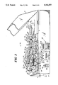
FIG. 1 is a perspective expanded view of a preferred embodiment of the automatic poultry vaccine injection and spray apparatus showing the modular casing construction and including the switch means, the spray apparatus and the separation means.
FIG. 2A illustrates an enlarged perspective view of the switch means, as shown in FIG. 1.
FIGS. 2B, 2C and 2D are top, front and side views of the same switch means.
FIG. 2E is a bottom view of the same switch means, illustrating the internal components, including the alarm means, with phantom lines.
FIG. 3 is a perspective view of the pneumatically controlled drive means of the apparatus.
FIG. 4 is a top view of the drive means of FIG. 3.
FIG. 5 is a cross-section top view of the drive means of FIGS. 3 and 4.
FIG. 6A and 6B are cross-sectional side views of a bidirectional flow check valve, as shown in FIG. 3.
FIG. 7 is a side elevational view of the separation means, the switch means and the spray apparatus of FIG. 1, and a side view of the control panel.
DETAILED DESCRIPTION OF THE PREFERRED EMBODIMENT
Referring now in more detail to the drawings, in which like numerals indicate like parts throughout the several views, FIG. 1 illustrates a front perspective view of the automatic injection spray apparatus 10. The automatic injection and spray apparatus 10 is housed in a casing construction 11 divided into an upper housing 12 and a lower housing 13. The upper housing 12 includes a plurality of side and top panels 14a, 14b, 14c, 14d, a sloped work surface 16, and a base 105. The lower housing 13 includes a plurality of side, top and bottom panels such as top, side, and front panels 15a, 15b, and 15c. As best shown in FIGS. 3-5, the upper housing 12 houses drive means 101, syringes 141, 151, and hypodermic needle 191. Switch means 41 (FIG. 1) and spray apparatus 91 are mounted on upper housing 12, as described in more detail below.
The lower housing 13 houses separation means 21 (FIG. 1) and most of the pneumatic logic circuitry (not shown) required to control the drive means 101. In addition, controls 263, including power switch 266, pressure gauge 265, regulator control knob 264, and counters 268, 269, 271 are mounted on side panel 15d of the lower housing 13 (FIG. 3).
As shown in FIG. 3, compressed air from a compressed air source (not shown) enters lower housing 13 through air supply input terminal 9. The compressed air is controlled by the pneumatic logic circuitry and moves between the lower housing 13 and the upper housing 12 through pneumatic connectors 36a-36g located on the top panel 15a of lower housing 13, which fit securely into mating pneumatic sockets located on the bottom side of base 105.
As illustrated in FIG. 1, the upper housing 12 is securely mounted to the lower housing 13 using alignment pins 18a-18d (FIG. 1) which are mounted to the bottom side of base 105 and are designed to fit into corresponding alignment holes 19a-19d, located on top panel 15a of the lower housing 13. In addition locking pins 38a, 38b and designed to fit into locking slots 39a, 39b, respectively, and can be turned a quarter-circle to lock upper housing 12 onto lower housing 13.
Switch means 41 includes switch housing 42 mounted on the sloped work surface 16 adjacent a hypodermic needle aperture 17 and on top of air supply apertures 59, 69, 79.
A spray apparatus 91 can be mounted on top of switch housing 42 by inserting mounting post 92 into mounting hole 85. Spray nozzles 94a, 94b are mounted on nozzle mount 93, which, in turn, is clamped to mounting post 92 so that during operation spray nozzles 94a, 94b are several inches above sloped work surface 16. Spray vaccine is supplied to the spray nozzles 94a, 94b through conduit 231, which extends from within upper housing 12 and through spray vaccine aperture 96. The control and flow of the spray vaccine is described in greater detail below and with reference to FIGS. 3, 4, 5, 6.
The automatic injection and spray apparatus 10 also includes separation means 21 for separating inoculated chicks from chicks placed on the sloped work surface 16 but not inoculated by the apparatus 10. The separation means 21 includes a deflector plate 22 pivotally mounted to panel 15c of lower housing 13. After a chick has been inoculated by apparatus 10, deflector plate 22 pivots away from lower housing 13, as shown by direction arrow 29, and the vaccinated chick, sliding down sloped work surface 16, is collected in container 30. If the apparatus 10 does not cycle, deflector plate 22 remains adjacent lower housing 13 and the unvaccinated chick slides down sloped work surface 16 and is collected in container 31 for reinoculation. The components and operation of separation means 21 are described in more detail below and with reference to FIG. 7.
FIGS. 2A, 2B, 2C and 2D illustrate various views of switch means 41. Switch means 41 comprises switch housing 42 which includes top surface 43a, bottom surface 43b (FIG. 2E) and side surfaces 43c-43h, sloped hand rest surface 44, first and second abutment surfaces 45, 46 and chick head retaining surface 48, which is part of chick retention means 47. First and second abutment surfaces 45, 46 are located substantially at right angles relative to each other and to the sloped work surface 16. Switch housing 42 is placed on sloped work surface 16 so that air supply connectors 58, 68, 78 (FIGS. 2C and 2D) protrude into upper housing 12 through air supply apertures 59, 69, 79 (FIG. 1). Switch housing 42 is firmly mounted to sloped work surface 16 by inserting screws (not shown) from the inside of upper housing 12 into threaded bores 83, 84, which protrude through bottom and top surfaces 43b, 43a of switch housing 42. First and second switch actuator means 51, 61 are correspondingly mounted in first and second abutment surfaces 45, 46
Referring now to FIG. 2E, first switch actuator means 51 comprises a plug 52, which has a plug head 53 and a plug shaft 54 movably mounted within cavity 56 and adapted to engage ball 55. Second switch actuator means 61 comprises a plug 62, which has a plug head 63 and a plug shaft 64, movably mounted within cavity 66 and adapted to engage ball 65. During operation compressed air moves from air supply connectors 58, 68 to outlet openings 57b, 67b through cavities 56, 66 and out outlet openings 57a, 67a, respectively. When plugs 52, 62 are depressed flush with abutment surfaces 45, 46, plug heads 53, 63 shut off the flow of air through outlet openings 57a, 67a and plug shafts 54, 64 engage balls 55, 65 to shut off the flow of air through outlet openings 57b, 67b, respectively. The stoppage of air through both switch actuator means 51, 61 is detected by a sensor, which, in turn, actuates drive means 101 (FIGS. 3, 4, 5) as described in more detail below.
As shown in FIG. 2E, alarm means 71 is housed in alarm housing 72. Alarm housing 72 is mounted into the bottom surface 43b of switch housing 42 by inserting screw 86 (FIGS. 2A and 2B) into threaded bore 87. Alarm means 71 includes a ball 74 movably mounted within circular column 75. When alarm means 71 is actuated, compressed air enters air supply connector 78 and is directed into circular column 75 by air input 73. The compressed air causes the ball 74 to travel around circular column 75, which creates a rattling noise or alarm. The air pressure in alarm housing 72 is released through exhaust ports 77 and into upper housing 12 in order to increase the pressure within the upper housing and help flush out any contaminants that might have collected in the upper housing.
FIGS. 3, 4, and 5 illustrate a perspective view, a top view and a top cross-sectional view of the pneumatically driven mechanical drive means 101 of the automatic injection and spray apparatus 10. The drive means 101 is mounted in upper housing 12 on base 105 using mounting blocks 106, 107, 108. The drive means 101 includes a drive cylinder 131, a drive piston 132, a hypodermic needle 191 and disposable syringes 141, 151.
The drive cylinder 131 is movably mounted within mounting block 107 and firmly attached to a carriage 109 using nut bolt 133 and air supply connector 137. The drive cylinder 131 is designed to translate the carriage 109 along a longitudinal axis 102 between an initial resting position adjacent the rear side of mounting block 107 and a fully extended position where nut bolt 133 engages a limit switch 121 on the front side of mounting block 106. The drive piston 132 is movably mounted within drive cylinder 131 and, upon actuation of drive means 101, translates along the longitudinal axis 102 of the drive cylinder 131 toward the hypodermic needle aperture 17 located in the sloped work surface 16 (FIG. 1). A rigid tubular 173, also extending along the longitudinal axis 102, if fixedly attached to a threaded end-portion 171 of the drive piston 132 with a nut 172 and is movably mounted within mounting block 108. The hypodermic needle 191 is fixedly mounted to a threaded surface 176 at the end of rigid tubular 173 using screw clamp 192. The hypodermic needle 191 reciprocates through the hypodermic needle aperture 17 in response to the movement of the rigid tubular 173, which moves in response to the movement by the drive piston 132.
Because it is necessary for the beveled tip 193 of the hypodermic needle 191 to remain at a proper orientation relative to each chick inoculated, the screw clamp 192 securely attaches the hypodermic needle 191 to the rigid tubular 173. The rigid tubular 173 is prevented from rotating by screwing a hexagonal tubular sheath 179 onto the threaded surface 176 of rigid tubular 173 and by shaping the longitudinal surface of guide chamber 181 of mounting block 108 to fit the size and shape of the tubular sheath 179.
In addition, it is necessary to control the distance the hypodermic needle 191 protrudes through the sloped work surface 16 when extended by the drive piston 132. This is accomplished by threading and pressure locking nut bolts 177, 178 along threaded surface 176 of rigid tubular 173 a predetermined distance from mounting block 108. In this manner the drive piston 132 and the rigid tubular 173 translate along the longitudinal axis 102 between an initial resting position where nut 172 engages a threaded end-portion 134 of the drive cylinder 131 and a fully extended position where nut bolts 177, 178 engage mounting block 108.
Retraction cylinders 161, 163 are fixedly mounted to mounting block 107. Correspondingly, retraction pistons 162, 164 are movably mounted within retraction cylinders 161, 163, and are fixedly mounted to the carriage 109 by hex nuts 188, 189. The retraction cylinders 161, 163 are used to assist drive cylinder 131 in returning carriage 109 to its initial resting position adjacent counting block 107.
Injection syringe 141 comprises a plunger 147 slidably mounted within a barrel 142. The barrel 142 in mounted into horizontal slot 145 (FIG. 3) of the carriage 109 so that the barrel rim 143 is retained in vertical slot 144. Locking screw 146 holds the barrel 142 securely in place. Plunger 147 is mounted into slot 149 of mounting block 106 so that plunger head 148 is retained in cavity 115 created between cavity surface 119 of mounting block 106 and cavity surface 117 of dosage block 111. Dosage block 111 is substantially C-shaped and is mounted on the right side of mounting block 106 using screw 113.
A spray syringe 151, comprising a plunger 157 slidably mounted within a barrel 152, is mounted on the side of carriage 109 opposite the injection syringe 141. Locking screw 156 holds the barrel 152 securely in a horizontal slot (not shown) similar to slot 149. The plunger 157 is mounted into vertical slot 159 of mounting block 106 so that plunger head 158 is retained in cavity 116 created between cavity surface 120 of mounting block 106 and cavity surface 118 of dosage block 112. Dosage block 112 is substantially reversed C-shaped and is mounted on the left side of mounting block 106 using a screw (not shown).
Bidirectional flow check valves 201, 236, which direct the flow of vaccine to and away from the syringes 141, 151, and to needle 191 are each securely mounted in recessed grooves 222, 257, located in the base 105 of the upper housing 12, using spring-loaded retention plates 221, 256 respectively. The internal components and the operation of both bidirectional flow check valves 201, 236 are described in more detail below and with reference to FIG. 6.
The injection syringe 141 controls the flow of vaccine from vaccine supply 7 through bidirectional flow check valve 201 and to the hypodermic needle 191. Conduit 194 supplies vaccine from vaccine supply 7 to the bidirectional flow check valve 201 at input connector 197. Conduit 195 connects the barrel 142 of the injection syringe 141 with connector 198 of the bidirectional flow check valve 201. Conduit 196 connects the output connector 199 of the bidirectional flow check valve 201 with the hypodermic needle 191. Conduit 196 enters a cavity 175 located on the smooth surface 174 of rigid tubular 173, extends along the hollowed shaft of rigid tubular 173 and is firmly connected to the hypodermic needle 191 using screw clamp 192.
The spray syringe 151 controls the flow of vaccine from vaccine supply 8 through a bidirectional flow check valve 236 and to the spray apparatus 91. Conduit 229 supplies vaccine from vaccine supply 8 to the bidirectional flow check valve 236 at input connector 232. Conduit 230 connects the barrel 152 of the spray syringe 151 with connector 233 of the bidirectional flow check valve 236. Conduit 231, which extends through spray vaccine aperture 96 on the sloped work surface 16, connects the output connector 234 of the bidirectional flow check valve 236 with spray nozzles 94a, 94b of the spray apparatus 91.
Vaccine is injected from the syringes 141, 151 in response to the movement of the carriage 109 from its initial resting position to its fully extended position. Barrels 142, 152, fixedly mounted on the carriage 109, are forced along the shaft of plungers 147, 157 when the plungers 147, 157 are stopped by cavity surfaces 117, 118 respectively. In contrast, vaccine is aspirated into the syringes 141, 151 in response to the movement of the carriage 109 as it returns from its fully extended position to its initial resting position. Barrels 142, 152 are pulled down the shaft of plungers 147, 157 when the plunger heads 148, 158 engage cavity surfaces 119, 120 respectively.
For this reason, the vaccine dosage amounts can be decreased or increased by correspondingly increasing or decreasing the longitudinal distance between cavity surfaces 117 and 119 for injection dosage or between cavity surfaces 118 and 120 for spray dosage. In a preferred embodiment of this invention, dosage blocks 111 or 112 can be exchanged for different dosage blocks having larger or smaller cavities in order to vary the dosage level of each inoculation or spray vaccination.
FIGS. 6A and 6B illustrate a cross-sectional view of one of the bidirectional flow check valves. Bidirectional flow check valves 201 and 236 are structurally and functionally identical; however, specific reference is made only to bidirectional flow check valve 201 in communication with the injection syringe 141. The bidirectional flow check valve 201 comprises three main sections: a central chamber 210, an input cap 202 and an output cap 212. The input cap 202 includes the input connector 197, which defines an inlet opening 206. The input cap 202 is slidably mounted onto the central chamber 210 to create an input spring chamber 208 and an output sealing chamber 207, which connect with inlet opening 206. An o-ring 203 is placed in output sealing chamber 207 and a spring 205 is placed in physical communication with a ball 204 in input spring chamber 208. The output cap 212 includes the output connector 199, which defines an outlet opening 216. The output cap 212 is slidably mounted within the central chamber 210 to create an output spring chamber 218 and an input sealing chamber 217, which connect with outlet opening 216. An o-ring 213 is placed in input sealing chamber 217 and a spring 215 is placed in physical communication with a ball 214 in output spring chamber 218. T-chamber 211 is located within central chamber 210 and connects inlet spring chamber 208 and output spring chamber 218 with connector 198, mounted on top of central chamber 210.
When vaccine is aspirated or drawn into the injection syringe 141 (FIGS. 3, 4, 5) through connector 198, both balls 204, 214 are drawn toward T-chamber 211. Ball 204 is pulled away from o-ring 203, which allows vaccine to be drawn through inlet opening 206, output sealing chamber 207, input spring chamber 208, T-chamber 211 and connector 198. Spring 205 prevents ball 204 from sealing the intersection between spring chamber 208 and T-chamber 211. Ball 214, on the other hand, is pulled into sealing contact with o-ring 213; thus, effectively preventing the flow of vaccine through the input sealing chamber 217.
Correspondingly, when vaccine is dispersed or injected from injection syringe 141 (FIGS. 3, 4, 5) through connector 198, both balls 204, 214 are forced away from T-chamber 211. Ball 214 is pushed away from o-ring 213, which allows vaccine to move from connector 198 and through T-chamber 211, input sealing chamber 217, output spring chamber 218 and outlet opening 216. Spring 215 prevents ball 214 from sealing the intersection between spring chamber 218 and outlet opening 216. The ball 204, in this case, is forced into sealing contact with o-ring 203, effectively preventing a backflow of vaccine through output sealing chamber 207.
FIG. 7 illustrates a side view of the separation means 21, as described generally in FIG. 1. Separation means 21 comprises a deflector plate 22, a deflection cylinder 24, a deflection piston 25 and two containers 30, 31 for holding vaccinated and unvaccinated chicks, respectively. The deflection cylinder 24 is mounted within a sheath 32, which is pivotally attached with a pin 33 to a clevis 26, mounted onto the bottom panel 15f of the lower housing. The deflection piston 25 is movably mounted within the deflection cylinder 24 and is pivotally attached, at its protruding end, with a pin 28 to a clevis 27, mounted onto the back side of the deflector plate 22. The deflection piston 25 translates through a deflector plate aperture 23 and along a longitudinal axis 49 of the deflection cylinder 24 upon actuation of the separation means 21. The deflector plate 22, which is pivotally mounted near the top of the lower housing 13, pivots away from the front panel 15e, as shown by direction arrow 29, in response to the movement by the deflection piston 25. In this manner, an inoculated chick sliding down sloped work surface 16 is diverted from falling into container 31 and, instead, falls into container 30.
SYSTEM OPERATION
Initially the upper housing 12, including the switch means 41 and the spray apparatus 91, is properly mounted on and connected to the lower housing 13. Vaccine from vaccine supplies 7, 8 are connected to the two- way check valves 201, 236 at connectors 197, 232 using conduits 194, 229, respectively. The desired number of chicks per inoculation run is set using counter 269 mounted in counter assembly 267. Run counter 268 and cumulative counter 271 are set to zero using reset buttons 272, 273, respectively.
An external high pressure fluid source, preferably compressed air, is connected to the automatic injection and spray apparatus 10 at air supply input terminal 9. The air pressure into the system is controlled by turning the regulator control knob 264 and reading the pressure on gauge 265. At start up, the drive means 101 and the separation means 21 are at their initial resting positions. The power switch 266 is turned to the "manual" position to cause the apparatus 10 to cycle several times in order to remove any air in the vaccination lines between vaccine supplies 7, 8 and the hypodermic needle 191 and the spray nozzles 94a, 94b. Once the air has been removed, the power switch 266 is turned to the "auto" position, and the apparatus 10 is ready to begin the inoculation process.
When the power switch 266 is turned to the "auto" position, compressed air flows from the external compressed air source, through input terminal 9 and into the pneumatic logic circuitry 261. Compressed air is directed past an air flow detection sensor 262 (not shown), located in the lower housing 13, and to the upper housing 12 through the connector/socket interchange 36a, 37a. This compressed air is divided and sent to both switch actuator means 51, 61 through conduits 186, 187, which connect connectors 183, 184 on mounting block 108 to connectors 58, 68 mounted on the bottom surface 43b of the switch housing 42, respectively. Compressed air flows continuously through both switch actuator means 51, 61 and greatly reduces the chance of the switch means 41 from becoming clogged with contaminants.
The operator then begins inoculating chicks, one at a time, by placing each chick on the sloped work surface 16 adjacent the switch means 41. The back and head of the chick are placed against the abutment surfaces 45, 46, respectively, using chick retention means 47 as a guide. When both plugs 52, 62 are depressed against the abutment surfaces 45, 46, the sensor 262 detects the stoppage of compressed air flow through conduits 186, 187.
In response to stoppage of compressed air flow, sensor 262, in fluid communication with the pneumatic logic circuitry, actuates the expansion of drive means 101 as follows. Compressed air flows to the upper housing 12 through the connector/socket interchange 36c, and then from connector 135 on mounting block 107, through conduit 139 and into connector 137 on drive cylinder 131. The compressed air initially causes the drive piston 132 and the rigid tubular 173 to extend sufficiently until the hypodermic needle 191 protrudes through the hypodermic needle aperture 17 on sloped work surface 16 and penetrates the chick and bolt 178 engages mounting block 108. Once the drive piston 132 has reached its fully extended position, the continuing buildup of compressed air in the drive cylinder 131 behind the drive piston 132 causes the drive cylinder 131 to translate backwards, toward mounting block 106. Because the carriage 109 is attached to the drive cylinder 131, it too translates toward mounting block 106. Syringes 141, 151, mounted on the carriage 109, also move toward mounting block 106. Syringe plungers 147, 157 correspondingly move with the syringe barrels 142, 152 for a distance equivalent to the width of cavities 115, 116, at which point, plunger heads 148, 158 engage cavity surfaces 117, 118. Plungers 147, 157 are held in place while barrels 142, 152 continue to move along the shafts of the plungers 174, 157 in response to the continuing movement by the carriage 109. Vaccine is thus forced from the syringes 141, 151 to the hypodermic needle 191 and the spray nozzles 94a, 94b, as described above. The dosage amounts for injection and spraying are independently controlled by the cavity size of dosage blocks 115, 116.
When nut bolt 133 abuts mounting block 106, the flow of vaccine to the chick and the flow of compressed air into connector 137 are stopped and the compression of the drive means 101 is begun when nut bolt 133 at the end of the drive cylinder 131 engages limit switch 121 located on the front side of mounting block 106. The engagement of limit switch 121 allows compressed air supplied to the upper housing 12 through connector/socket interchange 36g, and held in conduit 126 between connector 122 and dual-input switch connector 125, mounted on the rear side of mounting block 106, to flow through conduit 127 between connector 123 and dual-input mounting block 106. This compressed air signal travels to the lower housing 13 through connector/socket interchange 36f, and is received by the pneumatic logic circuitry, which actuates the compression of the drive means 101. Compressed air then flows to the upper housing 12 through the connector/socket interchange 36e, and then from connector 136 on mounting block 107, through conduit 140 and into connector 138 on drive cylinder 131. The compressed air in front of the piston 132 causes the drive piston 132 and the rigid tubular 173 to return to their initial resting positions so that the hypodermic needle 191 is retracted back through the hypodermic needle aperture 17. Compressed air also flows to the upper housing 12 through the connector/socket interchange 36d, and then from connectors 165, 166 on mounting block 107, through conduits 169, 170 and into connectors 167, 168 on corresponding retraction cylinders 161, 163. The compressed air entering each retraction cylinder 161, 163 causes the retraction pistons 162, 164, which had been extended with the carriage 109, to retract into the corresponding retraction cylinders 161, 163 until the carriage 109 and the drive cylinder 131 are returned to their original resting positions.
The pneumatic logic circuitry, in response to the closing of limit switch 121, also actuates the separation means 21. Compressed air flows through conduit 89 and into connector 88 on deflection cylinder 24. The compressed air causes the deflection piston 25 to extend through the deflector plate aperture 23 until the deflector plate 22 is extended beyond container 31. The deflector plate 22 remains in an extended position for a sufficient time period to allow the chick to be released by the operator, slide down the sloped work surface 16 and fall into container 30. Compressed air then flows through conduit 99 and into connector 98 on the deflection cylinder 24. The compressed air causes the deflection piston 25 to retract into the deflection cylinder 24 until the deflector plate 22 returns to its resting position adjacent the front panel 15e of the lower housing 13. Thus, if a chick were placed on the sloped work surface 16 without actuating the switch means 41, the deflector plate 22 would remain in its resting position and the chick released by the operator would fall into container 31
Each actuation of the switch means 41 causes the run counter 268 and the cumulative counter 271 to increment. When the run counter 268 reaches the same count as the preset value stored by counter 269, the pneumatic logic circuitry disenables the switch means 41, which effectively prevents the apparatus 10 from cycling, and actuates the alarm means 71. Compressed air flows to the upper housing 12 through the connector/socket interchange 36b, and then from connector 182 on mounting block 108, through conduit 185 and into connector 78 on the bottom surface 43b of the switch housing 42 to actuate the alarm means 71. Exhaust from the alarm means 71 escapes through the exhaust ports 77 and into the upper housing 12 and acts to flush the upper housing 12 of contaminants. The alarm means 71 remains actuated and the switch means 41 remains disenabled until the operator resets the run counter 268.
The container 30 containing the inoculated chicks is then be removed for further processing and an empty, but identical, container 30 is put in its place. The operator begins the next inoculation run using the "missed" chicks, if any, from container 31. This process is continuously repeated throughout the work day. At the end of the day, the total number of chicks inoculated is displayed on the cumulative counter 271.
Cleanup of the apparatus 10 is relatively quick and easy. The syringes 141, 151, the conduits 194, 195, 196, 229, 230, 231 and the hypodermic needle 191 are disconnected and discarded. The upper housing 12 is then removed from the lower housing 13 and are subjected to a liquid wash down. The bidirectional check valves 201, 236 are the only components of the apparatus 10 that must be disinfected.
While this invention has been described in detail with particular reference to a preferred embodiment thereof, it will be understood that variations and modifications can be effected within the scope and spirit of the invention as described hereinbefore and as defined in the appended claims.