US5314455A - Thermal compress system - Google Patents
Thermal compress system Download PDFInfo
- Publication number
- US5314455A US5314455A US07/644,835 US64483591A US5314455A US 5314455 A US5314455 A US 5314455A US 64483591 A US64483591 A US 64483591A US 5314455 A US5314455 A US 5314455A
- Authority
- US
- United States
- Prior art keywords
- knee
- arms
- limb
- compartment
- cuff
- Prior art date
- Legal status (The legal status is an assumption and is not a legal conclusion. Google has not performed a legal analysis and makes no representation as to the accuracy of the status listed.)
- Expired - Lifetime
Links
Images


Classifications
-
- A—HUMAN NECESSITIES
- A61—MEDICAL OR VETERINARY SCIENCE; HYGIENE
- A61F—FILTERS IMPLANTABLE INTO BLOOD VESSELS; PROSTHESES; DEVICES PROVIDING PATENCY TO, OR PREVENTING COLLAPSING OF, TUBULAR STRUCTURES OF THE BODY, e.g. STENTS; ORTHOPAEDIC, NURSING OR CONTRACEPTIVE DEVICES; FOMENTATION; TREATMENT OR PROTECTION OF EYES OR EARS; BANDAGES, DRESSINGS OR ABSORBENT PADS; FIRST-AID KITS
- A61F7/00—Heating or cooling appliances for medical or therapeutic treatment of the human body
- A61F7/08—Warming pads, pans or mats; Hot-water bottles
-
- A—HUMAN NECESSITIES
- A61—MEDICAL OR VETERINARY SCIENCE; HYGIENE
- A61B—DIAGNOSIS; SURGERY; IDENTIFICATION
- A61B90/00—Instruments, implements or accessories specially adapted for surgery or diagnosis and not covered by any of the groups A61B1/00 - A61B50/00, e.g. for luxation treatment or for protecting wound edges
- A61B90/03—Automatic limiting or abutting means, e.g. for safety
- A61B2090/032—Automatic limiting or abutting means, e.g. for safety pressure limiting, e.g. hydrostatic
-
- A—HUMAN NECESSITIES
- A61—MEDICAL OR VETERINARY SCIENCE; HYGIENE
- A61F—FILTERS IMPLANTABLE INTO BLOOD VESSELS; PROSTHESES; DEVICES PROVIDING PATENCY TO, OR PREVENTING COLLAPSING OF, TUBULAR STRUCTURES OF THE BODY, e.g. STENTS; ORTHOPAEDIC, NURSING OR CONTRACEPTIVE DEVICES; FOMENTATION; TREATMENT OR PROTECTION OF EYES OR EARS; BANDAGES, DRESSINGS OR ABSORBENT PADS; FIRST-AID KITS
- A61F7/00—Heating or cooling appliances for medical or therapeutic treatment of the human body
- A61F2007/0001—Body part
- A61F2007/0039—Leg or parts thereof
- A61F2007/0042—Knee
-
- A—HUMAN NECESSITIES
- A61—MEDICAL OR VETERINARY SCIENCE; HYGIENE
- A61F—FILTERS IMPLANTABLE INTO BLOOD VESSELS; PROSTHESES; DEVICES PROVIDING PATENCY TO, OR PREVENTING COLLAPSING OF, TUBULAR STRUCTURES OF THE BODY, e.g. STENTS; ORTHOPAEDIC, NURSING OR CONTRACEPTIVE DEVICES; FOMENTATION; TREATMENT OR PROTECTION OF EYES OR EARS; BANDAGES, DRESSINGS OR ABSORBENT PADS; FIRST-AID KITS
- A61F7/00—Heating or cooling appliances for medical or therapeutic treatment of the human body
- A61F7/02—Compresses or poultices for effecting heating or cooling
- A61F2007/0268—Compresses or poultices for effecting heating or cooling having a plurality of compartments being filled with a heat carrier
- A61F2007/0273—Compresses or poultices for effecting heating or cooling having a plurality of compartments being filled with a heat carrier with openings in the walls between the compartments serving as passageways for the filler
- A61F2007/0274—Compresses or poultices for effecting heating or cooling having a plurality of compartments being filled with a heat carrier with openings in the walls between the compartments serving as passageways for the filler the walls being reduced to spot connections, e.g. spot welds
Definitions
- This invention relates to systems used in the application of heat or cold and compression to certain injured portions of the human body.
- the invention relates to a compress to be fitted around the knee of a human for applying therapeutic compression and cold or heat to the knee in a safer and more effective manner.
- the present invention includes a cuff with a watertight chamber shaped to envelope only the anterior and sides of the knee, including particularly the suprapatellar pouch. These are the areas where posttrauma body fluids accumulate and where cold and compression are most needed. While the cuff is economically fabricated from sheets of flat material, its novel design permits adjustable shaping so as to conform to the knee even when the knee and cuff are flexed at different angles. The cuff is held in place with an upper proximal strap and a lower distal strap that avoid the popliteal area and minimize constriction. When the cuff is applied to the knee, the straps are secured, but not tightened. Then a first amount of compression is applied to the knee by inflating the cuff to a reasonably predeterminable amount, which causes the chamber to expand. The expansion tensions the straps and applies compression to the areas of the knee under the chamber.
- the expansion of the cuff from inflation becomes greater in the area above the patella (where swelling is greatest) and the expansion is restricted in the area below the patella (where swelling is less).
- It is well known medically and tests demonstrate that venous flow is far more sensitive to constriction in the region of the distal strap and less sensitive in the thigh under the proximal strap.
- By limiting tightening of the distal strap little or no pressure is applied below the knee or in back of the knee and constriction of venous flow is further minimized.
- the inflation of the cuff can be achieved by either of two means.
- the cuff is strapped in place when empty and is then inflated with ice water which is supplied by a tube from a container that is elevated above the cuff and pressurized by gravity--a method similar to that disclosed as a Gravity Thermal Dilator in U.S. Pat. No. 2,026,747.
- the cuff is divided into two coextensive chambers.
- the inner chamber is filled with ice and water before application to the knee.
- the outer chamber is inflated by a hand-held pump or bulb, in a manner somewhat similar to that disclosed in Davis's Thermal Pressure Splint, U.S. Pat. No. 3,548,819.
- the amount of inflation (and compression on the knee) can then be observed with a pressure indicating device such as that described in commonly assigned copending application Ser. No. 07/502,806, incorporated by reference herein in its entirety, or by the extension bellows type gauge herein disclosed.
- the unique effectiveness of the present invention in limiting constriction of venous circulation while applying effective compression to the knee can be demonstrated using a technique similar to pneumatic plethysmography.
- the lower leg is elevated about 12" above the hip, and a pneumatic cuff is fastened around the calf and inflated to a consistent base-line pressure.
- Three pneumatic pressure probes are attached to the knee to measure pressure above the patella, under the proximal strap and under the distal strap.
- a compression dressing such as an ace wrap or the dressing of the present invention is applied to the knee and compressed to a predetermined effective level, such as 28 mm hg. If the dressing constricts venous flow the calf will swell from the trapped blood and pressure in the cuff will rise. Greater swelling means greater venous constriction and greater risk.
- the pressures measured at the back of the knee under the straps (or at the same location with the ace bandage).
- the pressures around the knee are generally uniform.
- Proximal and distal pressures at the back of the leg are the same as above the patella.
- the pressure under the proximal strap is at one level; however, under the distal strap the pressure is significantly lower, typically only 55% or 60% as high as under the proximal strap and there is no pressure on the popliteal area (the back of the knee).
- a cuff was constructed as a complete cylinder completely enveloping the knee, similar to that disclosed by Cryomed.
- the calf pressure When inflated with water to the same 28 mm hg pressure at the knee, the calf pressure swelled by about 17 mm--an amount comparable to the swelling with an ace wrap, and far greater than with the present novel device.
- a further advantage with the invention developed herein is the ease with which compression can be periodically reduced without removing the dressing or adjusting the straps.
- the water from the cuff is routinely recycled back to the cooler for rechilling by lowering the cooler below the cuff.
- the pressure in the cuff falls to zero. This permits even any minimal pooling of blood that might occur in the veins to be flushed out.
- the pressure can easily be dropped periodically, without disturbing the straps or rewrapping the dressing, as with conventional devices.
- a dressing with a watertight chamber for application of pressure and cold to the knee that covers only about the anterior half of the knee, avoids the popliteal area, and is held in place by a pair of adjustable straps at the proximal and distal margin, with means for inflating and thereby expanding the dressing so as to apply compression to the knee after the straps are secured without, or with minimal, tensioning.
- the invention also provides means for relatively restricting the expansion of the dressing in the distal area so as to limit tensioning of the distal strap in order to lessen venous constriction.
- the restricting means is accomplished by tethering or spot-welding the layers of the dressing watertight chamber in the distal area.
- the novel device has a proximal strap that is inelastic and a distal strap that is elastic to further limit distal constriction.
- the invention includes a closed cycle pressurization means that uses chilled water from an elevated container that is connected by a tube to the watertight chamber of the device. By raising the container above the knee, the chilled water pressurizes the device and, when the water is warmed by the body, by lowering the container below the knee, the water is returned from the device to the container for recooling.
- a compartment of the device may be inflated with air by a novel pump or by a bulb.
- the invention is fabricated from sheets of flat material, but the novel design permits adjustable shaping of the invention so as to conform to the knee even when the knee is flexed at different angles.
- the novel invention also includes a syphon in the closed chilled water system that permits draining the water from the device without removing the cuff.
- the present invention relates to a device for treating an injured knee, comprising means for applying therapeutic cold and compression only to the general area of the suprapatellar pouch and to the general area alongside the knee, means coupled to the compression applying means for limiting compression applied to the general area alongside the knee while simultaneously allowing a predetermined greater compression to be applied to the general area of the suprapatellar pouch, and means for attaching the cold and compression applying means to the knee.
- the device comprises a fluid impervious chamber of flexible material having an upper transverse portion and depending arms extending from the transverse portion.
- the transverse portion is adapted to encompass a portion of the thigh above the knee in the general area of the suprapatellar pouch, and the depending arms are adapted to encompass the limb in the areas generally along the sides of the knee and a portion of the limb below the knee while exposing the patella.
- the chamber is adapted for receiving and containing a thermal fluid for abutting contact with the encompassed portion of the limb.
- An adjustable length inelastic strap extends under the thigh from one end of the transverse portion to the other end for holding the transverse portion of the chamber in encompassing engagement with the general area of the suprapatellar area above the knee.
- An elastic strap extends under the limb from one of the depending arms to the other depending arm to adjust their position with respect to each other while a third adjustable length strap, either elastic or inelastic, extends over the top of the limb from inside of one of the depending arms to the inside of the other depending arm to hold the arms securely against the limb.
- the invention also includes the fluid impervious chamber being divided into inner and outer compartments, each having an outer wall and a common wall.
- the inner compartment is adapted for receiving and containing a thermal fluid and can be placed in abutting contact with the encompassed portion of the limb being treated.
- Open-cell urethane foam material is provided in the outer compartment to insulate the underlying inner compartment, to minimize sweating of the outer compartment in humid climates and to maintain the shape of the device while permitting conformation of the device to encompass the person's limb.
- Selectively closable means is attached to the outer compartment for permitting a fluid to be introduced therein sufficient to force the inner compartment with its thermal fluid in pressure engagement with the encompassed portion of the limb.
- the expansion of the inner chamber in the distal area of the arms is restricted, thereby to cause a greater amount of thermal fluid to reside in the proximal area and allow less thermal fluid in the distal area of the inner chamber, resulting in greater compression in the proximal area and less in the distal area. In this manner less venous constriction occurs in the leg below the knee.
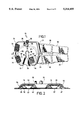
- FIG. 1 is a top plan view of the preferred embodiment of the novel pressure cuff
- FIG. 2 is a cross-sectional view of the cuff shown in FIG. 1, taken in the direction of the arrows 2--2;
- FIG. 3 is a top plan view of an alternate embodiment of the novel pressure cuff
- FIG. 4 is a bottom plan view of the pressure cuff of FIG. 3;
- FIG. 5 is a cross-sectional view of the embodiment of the thermal compress shown in FIG. 3 along the line 5--5 illustrating spot welding to hold the wall of the inner compartment together in predetermined areas;
- FIG. 6 is a cross-sectional view of an alternate embodiment of the thermal compress at the same section as 5--5 and illustrating tethers that hold the walls of the inner compartment in spaced relationship;
- FIG. 7 is a diagrammatic representation of the novel pressure cuff placed about the knee of an extended leg
- FIG. 8 is a view of the novel device placed on a flexed knee with one form of air pump attached thereto;
- FIG. 9 is a view of the novel thermal compress placed on a flexed knee with the air pump attached thereto and folded after the compress has been inflated;
- FIG. 10 is a side view of the compress quick disconnect in its connected relationship with the air pump hose
- FIG. 11 is a side view of the compress quick disconnect after being disconnected from the air pump hose
- FIG. 12 is a top view of one embodiment of the portable air pump used to pressurize the thermal cuff.
- FIG. 13 is a cross-sectional view of the air pump taken along lines 13--13 of FIG. 12;
- FIG. 14 is a side view of a bulb-type pump that may be used to pressurize the thermal cuff
- FIG. 15 is a cross-sectional view of a thermal cuff with a pressure gauge thereon.
- FIGS. 16A-16D are cross-sectional views of the pressure gauge in its various positions to indicate pressure in the thermal cuff compartments.
- the novel thermal compress of the present invention can be used to apply cold or hot temperatures to the human body, it will be described herein with respect to providing a cold temperature where its greatest use is anticipated.
- the preferred embodiment of the novel thermal compress device or cuff designated generally by the numeral 10 is designed to be applied to the knee of the leg of an individual.
- the cuff 10 has an upper transverse portion 12 and lower depending arms 13 and 14 extending from the upper portion 12.
- the cuff 10 can be wrapped about the knee portion of a leg.
- the opening designated by the numeral 18 in the cuff 10 is intended to receive the knee cap or patella as will be shown hereafter. In this way, the pressure and temperature are not applied to the patella or kneecap of the person wearing the compress.
- a proximal strap 20 and a distal strap 22 are attached to thermal compress cuff 10 at tabs or wings 21 and 23, respectively, on arm 14.
- Strap 22 is made of any well-known flexible material having a portion with a fastening material thereon known as Velcro.
- Strap 20 is made of a relatively inelastic material. Straps 20 and 22 are arranged for attaching relationship with mating Velcro strips 32 and 34 mounted on opposing tabs or wings 31 and 33, respectively, on arm 13 of thermal compress cuff 10. Further, the straps 20 and 22 have resilient foam attachments 28 and 30 attached respectively thereto for the purpose of providing a cushion for the underside of the person's leg to which the thermal compress cuff 10 is attached.
- a neck 25 has a closable opening 26 therein for admitting the cold liquid to the interior of the cuff 10.
- the cuff 10 is bifurcated beginning with opening 18, thus separating depending arms 13 and 14. This permits adjustment for knee angle and width.
- the gap between the arms 13 and 14 includes a truncated triangular gap 19.
- the gap 19 changes the profile of the applied cuff 10 from flat to conical for better conformation of the arms 13 and 14 to the leg when the knee is in the flexed position.
- Velcro fastener 34 and elastic strap 22 connect the depending arms 13 and 14 together under (or behind) the leg while strap 36 and mating Velcro strip 38 connect the arms 13 and 14 together over the top of the leg.
- the upper (proximal) and lower (distal ) straps 20 and 22 are placed so as to avoid the popliteal area of the knee and minimize constriction thereof.
- This construction permits bending adjustment of the cuff for different degrees of flexation of the knee from full extension to about 30°.
- the arms 13 and 14 could be fixed permanently to each other with flexible connectors without providing for adjustment if desired.
- the use of the flexible and elastic strap 22 under the leg tends to limit the constriction of the leg below the knee and thus minimizes venous constriction below the knee which is desirable during treatment of the knee by use of the cuff 10.
- FIG. 2 is a cross-sectional view of the novel cuff.
- the device 10 includes a fluid impervious chamber formed so as to be divided into inner and outer generally coextensive compartments 42 and 44, respectively.
- Compartment 42 has an outer wall 52 and compartment 44 has an outer wall 54.
- Each of the compartments 42 and 44 has a common inner wall 56.
- the inner compartment 42 is adapted for receiving and containing the thermal fluid in a desired temperature range in generally uniform and abutting contact via wall 52 with the encompassed portion of the leg being treated.
- a Y-shaped internal syphon having tubes 27 and 29 connects to neck 25 and closable opening 26 for filling and draining the fluid from inner compartment 42.
- Tubes 27 and 29 are formed of a material such as plastic and are approximately 5/16" on the inside diameter. They extend from the fill opening 26 to the distal end of each of the arms 13 and 14 as shown in phantom lines in FIG. 1. Thus, even though the fill port 26 is at the top of the compress, all of the fluid can be completely drained from the bottom.
- An open-cell urethane foam material 46 approximately 0.30" thick that will compress to about half its normal thickness under a 1 psi load is suitable for use in outer compartment 44 for insulating the underlying inner compartment 42, for minimizing sweating of the outer compartment 44 and for maintaining the shape of the cuff 10 while permitting conformation of the cuff 10 while encompassing the person's leg.
- the proximal strap 20 and distal strap 22 secure the cuff to the leg snugly but not tightly as described earlier.
- the cuff may be pressurized with a fluid from an elevated container using a closed cycle system.
- a cooler or container 88 which may be either a flexible pouch or a rigid container, holds a fluid such as ice and water sufficient for six to eight hours of cryotherapy.
- the cooler 88 if a rigid container, has a lid 84 and a handle 85 and is coupled by a hose 90 to the connection 26 on the cuff 10.
- the cooler 88 is elevated above the limb as illustrated in FIG. 7 and the ice chilled water flows into the cuff 10. Compression of the limb, due to the gravity flow of the ice water, is proportional to the elevation of the cooler 88 with respect to the cuff 10.
- a manually operated valve 92 allows the flow of ice water to be stopped when the desired pressure is reached by manually closing the valve. Thus, the pressure is sealed in the cuff and skin temperature falls rapidly. After 15 to 30 minutes, body heat will warm the water in the cuff 10. The water is then "rechilled” by reversing the cycle. The cooler is lowered below the leg and the valve 92 is opened. The warmed water is drained by the syphon system back into the cooler 88. After a short interval allowing mixing of the water with the ice, the cooler 88 is again elevated and the cuff-filling process repeated.
- a closed chilled water system is used and the water is recirculated between the container and the cuff in the closed system to maintain the water at the desired temperature.
- the Y-shaped internal syphon tubes 27 and 29 extend to the distal areas of the inner compartment 42 of arms 13 and 14, thus either draining the warm water from or filling the compartment with cold water as set forth above.
- the vent 35 (FIGS. 1 and 2) may be opened to allow air to escape as the chilled water is entering the compartment 42.
- the cuff 10 As thermal fluid fills the inner compartment 42, it expands the cuff 10, compresses the limb 16 and tightens the straps 20 and 22. Normally, the cuff 10 would expand uniformly and both straps would be similarly tensioned around the upper and lower limb. Because most of the swelling after knee surgery takes place in the suprapatellar pouch--immediately above the knee, it is medically desirable to have more cold and compression in the proximal area above the patella and less in the distal area covered by the arms 13 and 14. Additionally, the risk of undesirable constriction is greater under the distal strap below the knee.
- the present invention includes means to restrict the amount of expansion of the fluid compartment in the distal area of the cuff or compress 10 but not in the proximal area. This causes more fluid to remain in the upper area 12 and less in the arms 13 and 14. This results in less tightening of the lower strap 22.
- the simplest and preferred manner of accomplishing this is to spot weld the two sides 52 and 56 of the chamber in the area 57 of the distal portion of arms 13 and 14, similar to the manner of a quilt, as illustrated. (See FIGS. 2 & 5).
- An alternative is to weld a short tethering strap 57' to each internal surface 52 and 56 as shown in FIG. 6, to permit some but limited expansion in the immediate area. Tests show that pressure under the distal strap 22 is reduced by about a third by this dual technique of an elastic strap and restricted expansion of the chamber.
- the outer compartment 44 contains foam 46 that overlies the thermal fluid-filled compartment 42.
- the foam-filled outer compartment 44 performs two functions. First, it insulates the underlying cold fluid compartment 42, thereby maintaining the cold temperature for a longer period of time while preventing sweating of the cuff upper surface 54. Second, it maintains the shape of the cuff 10 while permitting conformation of the cuff around the leg and it reduces sagging of the device under the weight of the fluid.
- the foam may be an open-cell urethane foam about 0.30 inches thick that will compress to about half its normal thickness under a 1 psi load.
- external compression is used to cause the outer wall 52 of the cold fluid compartment 42 to more uniformly engage the body area being treated. This is accomplished by applying a pressurized fluid such as air through a selectively closable opening 40 shown in detail in FIGS. 9-11.
- the selectively closable opening 40 (as shown in FIG. 3) is attached to the outer compartment 44 for permitting pressurized fluid such as air to be introduced therein sufficient to force the inner compartment 42 with its thermal fluid in pressure engagement with the encompassed portion of the leg. This increases the pressure in the foam-filled chamber 44.
- FIGS. 8, 9, 12 and 13 One form of a pump that may be coupled to orifice 40 for applying the supplemental pressure is illustrated in FIGS. 8, 9, 12 and 13.
- the pump is designated generally by the numeral 58. It has a rectangular body portion 60 to which is attached a strap 59 having a Velcro strip 61 thereon.
- a hose 62 extends from body portion 60 to carry the compressed air to opening 40 in the outer compartment or chamber 44 of the inflatable cuff.
- the unit may be folded about center section 66 and Velcro strap 59 wrapped around the open end of the air pump 58 to have mating contact with a second Velcro strip 70 (FIG. 13) on the obverse side of the pump 58.
- FIG. 13 A cross section of the novel pump is shown in FIG. 13.
- the pump 58 is actually an air foam cell that is approximately six inches long and two inches wide and has strap 59 attached therewith with the Velcro strip 61 thereon.
- the lower portion 72 is an air impervious resilient material such as plastic and has attached thereto first and second substantially rigid surfaces 74 and 76 which may be, for instance, thin, rigid plastic layers. Plastic layers 74 and 76 are separated from each other by a small gap 78.
- a cellular foam layer 80 has a portion removed to form an indentation 66 and allow the foam cell to be easily folded about the indentation.
- An outer pliable surface 82 such as this plastic is placed over the foam 80 and sealed to the lower plastic surface 72 to form an airtight compartment.
- Hose 62 communicates with the inside of the airtight compartment.
- the air cell When the air cell is folded about separation 78 and indentation 66 as shown in FIGS. 8 and 9, the entrapped air in the cell is forced out via tube 62 and orifice 64 into the cuff 10 as shown in FIG. 10.
- the hose 62 By clamping the selectively closable opening 40 with quick disconnect clamp 41, the hose 62 may be disconnected from orifice 64, as shown in FIG. 11, and the air cell 58 will expand to its straight configuration as in FIG. 12. In this process the cell 58 accumulates air through hose 62 to the interior thereof.
- the hose 62 can then again be coupled to the cuff 10 to add additional air as needed when the air cell 58 is again folded.
- a one-way valve may be coupled to the cell to allow air in but not out.
- the hose 62 would not have to be disconnected from the orifice 64.
- only one pressurization cycle of the pump 58 is required to sufficiently pressurize the cuff 10.
- the pump 58 When the pump 58 is not in use, it may be disconnected from the cuff 10 and folded as illustrated in FIG. 9 with the strap 59 passing around the open end of the pump and the Velcro strip 61 thereon cooperating with the Velcro strip 70 on the bottom of the air cell 58 to hold the pump in the closed shape as shown.
- a bulb 63 as shown in FIG. 14 and well known in the art, may be used to pressurize the outer compartment 44.
- the end 65 of bulb 63 may be inserted in a hose such as hose 62 or directly in connector orifice 40 to pressurize outer compartment 44.
- FIG. 15 is a cross-sectional view of the novel cuff in which a gauge means housing 100 has been placed to indicate the pressure in the outer compartment 44 so as to prevent over inflation.
- the gauge means housing 100 may include an expandable bellows 102 such as shown in FIG. 16A (where it is entirely compressed) in communication with chamber 44 via aperture 101.
- the bellows 102 is held in place with no pressure in compartment 44 by resilient means such as a spring 104.
- the bellows 102 begins to expand against the force of spring 104 and protrudes from the housing 100 as illustrated in FIG. 16B.
- the bellows 102 becomes fully extended as illustrated in FIG. 16C.
- the bellows may have markings 106 thereon as shown in FIG. 16D to indicate the amount of pressure within compartment 44.
- the marks 106 may simply be reference points to enable the user to adjust the same pressure in the compartment 44 each time the thermal compress is used.
- a novel thermal compress cuff which is adapted to encompass a knee of a person. It has a substantially fluid impervious chamber formed of flexible material having an upper portion and depending arms extending from the upper portion.
- the chamber is divided into inner and outer compartments each having an outer wall and a common wall.
- the inner compartment is adapted for receiving and containing a thermal fluid and is in abutting contact with the encompassed portion of the person's knee.
- An opening is formed in the inner compartment for receiving a thermal fluid through a hose from an external container. As the container is lifted above the knee, the thermal fluid is under pressure and pressurizes the inner compartment to an amount corresponding to the height of the container above the knee.
- Open-cell urethane foam in the outer compartment insulates the underlying inner compartment thus minimizing sweating of the outer compartment in humid climates. It also maintains the shape of the device while permitting conformation of the device encompassing the person's limb.
- a selectively closable opening is attached to the outer compartment for permitting pressurized fluid to be introduced therein sufficient to force the inner compartment with its thermal fluid in pressure engagement with the encompassed portion of the knee.
- Means for restricting expansion of the cavity in the distal area of the arms is provided to cause a greater amount of thermal fluid to remain in the proximal area (providing more pressure) and allow less thermal fluid in the distal area of the arms.
- a novel portable air cell is provided to pressurize the cuff as needed.
- the container 88 may be connected directly to neck 25 (FIG. 1) via a quick disconnect such as the type made by Colder Fittings (Model Nos. PLCD 170-06 & PLCD 220-06).
- neck 25 and opening 26 may be made large enough to permit the direct introduction of ice cubes and water in lieu of a separate container 88.
- the outer compartment 44 may be inflated orally by a tube connected to orifice 40.
Abstract
Description
Claims (29)
Priority Applications (8)
| Application Number | Priority Date | Filing Date | Title |
|---|---|---|---|
| US07/644,835 US5314455A (en) | 1991-01-23 | 1991-01-23 | Thermal compress system |
| US07/737,402 US5230335A (en) | 1991-01-23 | 1991-07-29 | Thermal compress system |
| AU12623/92A AU663075B2 (en) | 1991-01-23 | 1992-01-08 | Thermal compress system |
| EP92905129A EP0572476B1 (en) | 1991-01-23 | 1992-01-08 | Thermal compress system |
| CA002101272A CA2101272A1 (en) | 1991-01-23 | 1992-01-08 | Thermal compress system |
| DE69230370T DE69230370T2 (en) | 1991-01-23 | 1992-01-08 | THERMAL COMPRESSING SYSTEM |
| PCT/US1992/000131 WO1992013506A2 (en) | 1991-01-23 | 1992-01-08 | Thermal compress system |
| US08/109,382 US5466250A (en) | 1991-01-23 | 1993-08-19 | Automatic fluid compress and circulating system |
Applications Claiming Priority (1)
| Application Number | Priority Date | Filing Date | Title |
|---|---|---|---|
| US07/644,835 US5314455A (en) | 1991-01-23 | 1991-01-23 | Thermal compress system |
Related Child Applications (1)
| Application Number | Title | Priority Date | Filing Date |
|---|---|---|---|
| US07/737,402 Continuation-In-Part US5230335A (en) | 1991-01-23 | 1991-07-29 | Thermal compress system |
Publications (1)
| Publication Number | Publication Date |
|---|---|
| US5314455A true US5314455A (en) | 1994-05-24 |
Family
ID=24586530
Family Applications (1)
| Application Number | Title | Priority Date | Filing Date |
|---|---|---|---|
| US07/644,835 Expired - Lifetime US5314455A (en) | 1991-01-23 | 1991-01-23 | Thermal compress system |
Country Status (1)
| Country | Link |
|---|---|
| US (1) | US5314455A (en) |
Cited By (113)
| Publication number | Priority date | Publication date | Assignee | Title |
|---|---|---|---|---|
| US5637077A (en) * | 1995-10-30 | 1997-06-10 | Smith & Nephew Casting, Inc. | Custom-molded ankle brace |
| EP0979060A1 (en) * | 1997-03-10 | 2000-02-16 | Aquarius Medical Corporation | Improved apparatus and method for the core body warming of mammals experiencing hypothermia |
| US6117164A (en) | 1997-06-06 | 2000-09-12 | Dj Orthopedics, Llc | Flexible multijoint therapeutic pads |
| US6230501B1 (en) | 1994-04-14 | 2001-05-15 | Promxd Technology, Inc. | Ergonomic systems and methods providing intelligent adaptive surfaces and temperature control |
| US6238427B1 (en) | 1999-03-30 | 2001-05-29 | John G. Matta | Therapeutic heat transfer pads |
| EP1179328A1 (en) * | 2000-08-08 | 2002-02-13 | Gaymar Industries Inc. | Device for preventing body hypo/hyperthermia incorporating an open-cell dispersion system |
| US6588020B1 (en) | 2001-12-21 | 2003-07-08 | The Idea People Llc | Back support device with surgical area protection |
| US6695872B2 (en) | 2000-01-28 | 2004-02-24 | Coolsystems, Inc. | Therapy component of an animate body heat exchanger and method of manufacturing such component |
| US20040068310A1 (en) * | 2002-10-08 | 2004-04-08 | Howard Edelman | Therapy pad |
| US20040078864A1 (en) * | 2002-08-09 | 2004-04-29 | Miros Robert H. J. | Apparel including a heat exchanger |
| US6755798B2 (en) * | 2002-02-13 | 2004-06-29 | Aircast, Inc. | Pneumatic achilles sleeve |
| US20040158303A1 (en) * | 2002-04-29 | 2004-08-12 | Medcool, Inc. | Method and device for rapidly inducing and then maintaining hypothermia |
| US20040193084A1 (en) * | 2003-03-27 | 2004-09-30 | Arvik Enterprises, Llc | Vein compressor device |
| US20040210176A1 (en) * | 2003-01-06 | 2004-10-21 | Richard Diana | Method and device for treatment of edema |
| US20050020952A1 (en) * | 2003-06-06 | 2005-01-27 | Erez Pick | Pad with aircell for an orthopedic brace |
| US20050187503A1 (en) * | 2004-02-23 | 2005-08-25 | Elise Tordella | Compression apparatus |
| US20050187499A1 (en) * | 2004-02-23 | 2005-08-25 | Heather Gillis | Compression apparatus |
| US20050187501A1 (en) * | 2003-03-27 | 2005-08-25 | Sundaram Ravikumar | Compression apparatus for applying localized pressure to a limb |
| US20050209663A1 (en) * | 2003-09-24 | 2005-09-22 | Nathan Hamilton | Methods and apparatus for adjusting body core temperature |
| US20050256556A1 (en) * | 2004-05-17 | 2005-11-17 | Coolsystems, Inc. | Modular apparatus for therapy of an animate body |
| US20060030915A1 (en) * | 2003-08-04 | 2006-02-09 | Medcool, Inc. | Method and apparatus for reducing body temperature of a subject |
| US7008445B2 (en) | 2002-04-29 | 2006-03-07 | Medcool, Inc. | Method and device for rapidly inducing hypothermia |
| US20060111765A1 (en) * | 2004-11-19 | 2006-05-25 | Seacoast Technologies, Inc. | Medical device for thermally affecting tissue having an inflatable circumferential stiffening member |
| US20060122547A1 (en) * | 2004-12-06 | 2006-06-08 | Stewart Kenneth G Iii | Adjustable back support device |
| US20060173393A1 (en) * | 2003-02-25 | 2006-08-03 | Orhmihl-Danet | Inflatable splint for stabilisation of the ankle |
| US20070010770A1 (en) * | 2005-07-07 | 2007-01-11 | Gildersleeve Richard E | Pneumatic liner with pressure relief valve and method of supporting an extremity with a pneumatic liner with pressure relief valve |
| WO2007014242A1 (en) * | 2005-07-25 | 2007-02-01 | Djo, Llc | Temperature regulated compression brace |
| US20070142883A1 (en) * | 2005-12-15 | 2007-06-21 | Kimberly-Clark Worldwide, Inc. | Therapeutic kit employing a thermal insert |
| US20080021531A1 (en) * | 2003-09-24 | 2008-01-24 | Kane John R | Methods and apparatus for increasing blood circulation |
| US20080097561A1 (en) * | 2006-10-18 | 2008-04-24 | Medcool, Inc. | Dual cycle thermal system and method of use |
| US20080132816A1 (en) * | 2006-12-04 | 2008-06-05 | Kane John Roy | Methods and Apparatus for Adjusting Blood Circulation |
| US20080132976A1 (en) * | 2006-12-04 | 2008-06-05 | Kane John Roy | Methods and apparatus for adjusting blood circulation |
| US20080249449A1 (en) * | 2007-04-09 | 2008-10-09 | Tyco Healthcare Group Lp | Methods of Making Compression Device with Improved Evaporation |
| US20080249447A1 (en) * | 2007-04-09 | 2008-10-09 | Tyco Healthcare Group Lp | Compression Device Having Cooling Capability |
| US20080249455A1 (en) * | 2007-04-09 | 2008-10-09 | Tyco Healthcare Group Lp | Compression Device with Improved Moisture Evaporation |
| US20080249440A1 (en) * | 2007-04-09 | 2008-10-09 | Tyco Healthcare Group Lp | Method of Making Compression Sleeve with Structural Support Features |
| US20080269852A1 (en) * | 2005-04-07 | 2008-10-30 | Medcool, Inc | Methods and Apparatus for Thermal Regulation of a Body |
| US20090066079A1 (en) * | 2007-09-12 | 2009-03-12 | Coolsystems, Inc. | Make-brake connector assembly with opposing latches |
| US20090124944A1 (en) * | 2007-11-13 | 2009-05-14 | Sundaram Ravikumar | Method and Assembly for Treating Venous Ulcers and Wounds |
| US20090156973A1 (en) * | 2007-04-19 | 2009-06-18 | John Scott | Method of and apparatus for patella support |
| US20090177184A1 (en) * | 2008-01-09 | 2009-07-09 | Christensen Scott A | Method and apparatus for improving venous access |
| US20090312681A1 (en) * | 2008-06-16 | 2009-12-17 | Mcspadden Sam K | Method of and system for joint therapy and stabilization |
| USD608006S1 (en) | 2007-04-09 | 2010-01-12 | Tyco Healthcare Group Lp | Compression device |
| US20100030306A1 (en) * | 2002-10-08 | 2010-02-04 | Howard Edelman | Therapeutic Cranial Wrap for a Contrast Therapy System |
| US7658205B1 (en) | 2002-12-19 | 2010-02-09 | Vitalwear, Inc. | Systems for a fluid circuit coupler |
| US7694693B1 (en) | 2002-10-08 | 2010-04-13 | Vitalwear, Inc. | Mixing valve for a contrast therapy system |
| US20100137951A1 (en) * | 2002-12-12 | 2010-06-03 | Medcool, Inc. | Method and apparatus for reducing body temperature of a subject |
| US20100145421A1 (en) * | 2008-12-05 | 2010-06-10 | Coolsystems, Inc. | Therapeutic Cooling and/or Heating System Including A Thermo-Conductive Material |
| US20100139294A1 (en) * | 2008-12-05 | 2010-06-10 | Coolsystems, Inc. | Cooling System Having A Bypass Valve To Regulate Fluid Flow |
| US7837638B2 (en) | 2007-02-13 | 2010-11-23 | Coolsystems, Inc. | Flexible joint wrap |
| US20110098792A1 (en) * | 2009-10-22 | 2011-04-28 | Lowe Mark H | Therapeutic wrap |
| US20110106023A1 (en) * | 2009-11-04 | 2011-05-05 | Lowe Mark H | System for providing treatment to a mammal |
| US20110125183A1 (en) * | 2009-11-24 | 2011-05-26 | Circaid Medical Products | Graduated Compression Device for the Treatment of Circulatory Disorders |
| US20110172749A1 (en) * | 2010-01-08 | 2011-07-14 | Christensen Scott A | Methods and apparatus for enhancing vascular access in an appendage to enhance therapeutic and interventional procedures |
| US8021388B2 (en) | 2007-04-09 | 2011-09-20 | Tyco Healthcare Group Lp | Compression device with improved moisture evaporation |
| US8029450B2 (en) | 2007-04-09 | 2011-10-04 | Tyco Healthcare Group Lp | Breathable compression device |
| US8029451B2 (en) | 2005-12-12 | 2011-10-04 | Tyco Healthcare Group Lp | Compression sleeve having air conduits |
| US8034007B2 (en) | 2007-04-09 | 2011-10-11 | Tyco Healthcare Group Lp | Compression device with structural support features |
| US8052628B1 (en) | 2002-10-08 | 2011-11-08 | Vitalwear, Inc. | Spinal column brace for a contrast therapy system |
| US8114117B2 (en) | 2008-09-30 | 2012-02-14 | Tyco Healthcare Group Lp | Compression device with wear area |
| US8128584B2 (en) | 2007-04-09 | 2012-03-06 | Tyco Healthcare Group Lp | Compression device with S-shaped bladder |
| US8162861B2 (en) | 2007-04-09 | 2012-04-24 | Tyco Healthcare Group Lp | Compression device with strategic weld construction |
| US8235923B2 (en) | 2008-09-30 | 2012-08-07 | Tyco Healthcare Group Lp | Compression device with removable portion |
| US20130072838A1 (en) * | 2011-06-22 | 2013-03-21 | Gradcast LLC | Therapy cast |
| US8425579B1 (en) | 2002-10-08 | 2013-04-23 | Vitalwear, Inc. | Therapeutic knee brace for a contrast therapy system |
| US8506508B2 (en) | 2007-04-09 | 2013-08-13 | Covidien Lp | Compression device having weld seam moisture transfer |
| US8529613B2 (en) | 2006-10-18 | 2013-09-10 | Medcool, Inc. | Adjustable thermal cap |
| US8539647B2 (en) | 2005-07-26 | 2013-09-24 | Covidien Ag | Limited durability fastening for a garment |
| US8597217B2 (en) | 2010-12-30 | 2013-12-03 | Coolsystems, Inc. | Reinforced therapeutic wrap and method |
| US8652079B2 (en) | 2010-04-02 | 2014-02-18 | Covidien Lp | Compression garment having an extension |
| US20140213947A1 (en) * | 2013-01-31 | 2014-07-31 | Ossur Hf | Progressive Force Strap Assembly for Use with an Orthopedic Device |
| WO2015006210A1 (en) * | 2013-07-09 | 2015-01-15 | Reed Michael R | Athletic protector system |
| US8979915B2 (en) | 2010-04-19 | 2015-03-17 | Pulsar Scientific, LLC | Separable system for applying compression and thermal treatment |
| US9125787B2 (en) | 2011-09-30 | 2015-09-08 | Covidien Lp | Compression garment having a foam layer |
| US9205021B2 (en) | 2012-06-18 | 2015-12-08 | Covidien Lp | Compression system with vent cooling feature |
| US9220622B2 (en) | 2004-12-22 | 2015-12-29 | Ossur Hf | Orthopedic device |
| US9265645B2 (en) | 2004-12-22 | 2016-02-23 | Ossur Hf | Orthotic device and method for securing the same |
| US20160051404A1 (en) * | 2006-10-05 | 2016-02-25 | Ramsey Joe Choucair | Cold Compress for Therapeutic Cooling |
| US9358146B2 (en) | 2013-01-07 | 2016-06-07 | Ossur Hf | Orthopedic device and method for securing the same |
| US9375341B2 (en) | 2013-01-31 | 2016-06-28 | Ossur Hf | Orthopedic device having detachable components for treatment stages and method for using the same |
| US9402779B2 (en) | 2013-03-11 | 2016-08-02 | Covidien Lp | Compression garment with perspiration relief |
| US9474334B2 (en) | 2012-11-13 | 2016-10-25 | Ossur Hf | Fastener member for affixation to a structure in an orthopedic device and method for securing the same |
| US9498025B2 (en) | 2013-04-08 | 2016-11-22 | Ossur Hf | Strap attachment system for orthopedic device |
| USD772488S1 (en) | 2014-07-03 | 2016-11-22 | Michael R. Reed | Cup cooling liner |
| US9615967B2 (en) | 2010-12-30 | 2017-04-11 | Coolsystems, Inc. | Reinforced therapeutic wrap and method |
| US20170258631A1 (en) * | 2016-03-08 | 2017-09-14 | Monterey Bay Associates | Temperature-regulating sports wrap with angled attachments |
| US9814615B2 (en) | 2004-12-22 | 2017-11-14 | Ossur Hf | Orthopedic device |
| US9872812B2 (en) | 2012-09-28 | 2018-01-23 | Kpr U.S., Llc | Residual pressure control in a compression device |
| US9987186B1 (en) | 2013-12-10 | 2018-06-05 | Allie Lynch | Splinted compression bandage |
| US10052221B2 (en) | 2015-01-06 | 2018-08-21 | Ossur Iceland Ehf | Orthopedic device for treating osteoarthritis of the knee |
| USD834208S1 (en) | 2017-03-10 | 2018-11-20 | Tactile Systems Technology, Inc. | Chest and arm garment |
| US10342733B2 (en) | 2008-03-13 | 2019-07-09 | Medtronic Xomed, Inc. | Flexible, flat pouch with port for mixing and delivering powder-liquid mixture |
| US10456320B2 (en) | 2013-10-01 | 2019-10-29 | Coolsystems, Inc. | Hand and foot wraps |
| US10463565B2 (en) | 2011-06-17 | 2019-11-05 | Coolsystems, Inc. | Adjustable patient therapy device |
| USD882803S1 (en) | 2018-10-08 | 2020-04-28 | Ossur Iceland Ehf | Orthopedic shell |
| WO2020096204A1 (en) * | 2018-11-07 | 2020-05-14 | 고려대학교 산학협력단 | Functional joint assistive device |
| USD888258S1 (en) | 2018-10-08 | 2020-06-23 | Ossur Iceland Ehf | Connector assembly |
| US10751221B2 (en) | 2010-09-14 | 2020-08-25 | Kpr U.S., Llc | Compression sleeve with improved position retention |
| US10859295B2 (en) | 2016-04-13 | 2020-12-08 | ZeoThermal Technologies, LLC | Cooling and heating platform |
| USD908458S1 (en) | 2018-10-08 | 2021-01-26 | Ossur Iceland Ehf | Hinge cover |
| US10918557B2 (en) | 2009-11-24 | 2021-02-16 | Medi Manufacturing, Inc. | Two-part non-planar graduated compression device for the treatment of circulatory disorders |
| US11058599B2 (en) | 2015-10-05 | 2021-07-13 | Tactile Systems Technology, Inc. | Adjustable compression garment |
| US11154452B2 (en) | 2016-01-21 | 2021-10-26 | Tactile Systems Technology, Inc. | Compression garment system |
| US11234850B2 (en) | 2016-06-06 | 2022-02-01 | Ossur Iceland Ehf | Orthopedic device, strap system and method for securing the same |
| US11547589B2 (en) | 2017-10-06 | 2023-01-10 | Ossur Iceland Ehf | Orthopedic device for unloading a knee |
| US11638675B2 (en) | 2018-11-07 | 2023-05-02 | Zenith Technical Innovations, Llc | System and method for heat or cold therapy and compression therapy |
| US11648172B2 (en) | 2017-11-06 | 2023-05-16 | Tactile Systems Technology, Inc. | Compression garment systems |
| US11672693B2 (en) | 2014-08-05 | 2023-06-13 | Avent, Inc. | Integrated multisectional heat exchanger |
| US11744742B1 (en) | 2019-06-10 | 2023-09-05 | Todd R. Wurth | Cryotherapy dressing system |
| US11850175B2 (en) | 2016-06-06 | 2023-12-26 | Ossur Iceland Ehf | Orthopedic device, strap system and method for securing the same |
| US11857491B2 (en) | 2019-03-13 | 2024-01-02 | Breg, Inc. | Integrated cold therapy-compression therapy assembly and associated treatment protocols |
| US11857449B1 (en) | 2019-08-15 | 2024-01-02 | Preferred Prescription, Inc. | Compression braces with removable hot/cold packs |
| US11872150B2 (en) | 2020-12-28 | 2024-01-16 | Ossur Iceland Ehf | Sleeve and method for use with orthopedic device |
Citations (15)
| Publication number | Priority date | Publication date | Assignee | Title |
|---|---|---|---|---|
| US1732380A (en) * | 1928-08-21 | 1929-10-22 | Sarason David | Apparatus for the external treatment of parts of the body by water |
| US2026747A (en) * | 1935-03-16 | 1936-01-07 | William P B Nemzek | Gravity thermal dilator |
| US2832336A (en) * | 1955-06-23 | 1958-04-29 | Davis | Physiotherapy device |
| US3584819A (en) * | 1969-05-23 | 1971-06-15 | Amp Inc | Storage reel |
| US3633567A (en) * | 1969-08-11 | 1972-01-11 | Survival Technology | Pneumatically actuated pressure dressing |
| US3871381A (en) * | 1971-12-30 | 1975-03-18 | Donald J Roslonski | Cold compress device |
| US3901225A (en) * | 1974-01-02 | 1975-08-26 | Jerry W Sconce | Inflatable splint |
| US4139004A (en) * | 1977-02-17 | 1979-02-13 | Gonzalez Jr Harry | Bandage apparatus for treating burns |
| US4338944A (en) * | 1980-06-16 | 1982-07-13 | The Kendall Company | Therapeutic device |
| US4407276A (en) * | 1981-01-22 | 1983-10-04 | Medical Designs, Inc. | Brace for articulated limbs |
| US4628932A (en) * | 1984-06-11 | 1986-12-16 | Morris Tampa | Knee ice pack |
| US4688572A (en) * | 1986-01-21 | 1987-08-25 | Tecnol, Inc. | Medical/sports thermal pack |
| US4872448A (en) * | 1986-10-22 | 1989-10-10 | Johnson Jr Glenn W | Knee brace having adjustable inflatable U-shaped air cell |
| US4951665A (en) * | 1989-02-08 | 1990-08-28 | Hollister Incorporated | Insulating, anti-kinking Y connector for arthroscopic surgery and method of making |
| US4964402A (en) * | 1988-08-17 | 1990-10-23 | Royce Medical Company | Orthopedic device having gel pad with phase change material |
-
1991
- 1991-01-23 US US07/644,835 patent/US5314455A/en not_active Expired - Lifetime
Patent Citations (15)
| Publication number | Priority date | Publication date | Assignee | Title |
|---|---|---|---|---|
| US1732380A (en) * | 1928-08-21 | 1929-10-22 | Sarason David | Apparatus for the external treatment of parts of the body by water |
| US2026747A (en) * | 1935-03-16 | 1936-01-07 | William P B Nemzek | Gravity thermal dilator |
| US2832336A (en) * | 1955-06-23 | 1958-04-29 | Davis | Physiotherapy device |
| US3584819A (en) * | 1969-05-23 | 1971-06-15 | Amp Inc | Storage reel |
| US3633567A (en) * | 1969-08-11 | 1972-01-11 | Survival Technology | Pneumatically actuated pressure dressing |
| US3871381A (en) * | 1971-12-30 | 1975-03-18 | Donald J Roslonski | Cold compress device |
| US3901225A (en) * | 1974-01-02 | 1975-08-26 | Jerry W Sconce | Inflatable splint |
| US4139004A (en) * | 1977-02-17 | 1979-02-13 | Gonzalez Jr Harry | Bandage apparatus for treating burns |
| US4338944A (en) * | 1980-06-16 | 1982-07-13 | The Kendall Company | Therapeutic device |
| US4407276A (en) * | 1981-01-22 | 1983-10-04 | Medical Designs, Inc. | Brace for articulated limbs |
| US4628932A (en) * | 1984-06-11 | 1986-12-16 | Morris Tampa | Knee ice pack |
| US4688572A (en) * | 1986-01-21 | 1987-08-25 | Tecnol, Inc. | Medical/sports thermal pack |
| US4872448A (en) * | 1986-10-22 | 1989-10-10 | Johnson Jr Glenn W | Knee brace having adjustable inflatable U-shaped air cell |
| US4964402A (en) * | 1988-08-17 | 1990-10-23 | Royce Medical Company | Orthopedic device having gel pad with phase change material |
| US4951665A (en) * | 1989-02-08 | 1990-08-28 | Hollister Incorporated | Insulating, anti-kinking Y connector for arthroscopic surgery and method of making |
Non-Patent Citations (25)
| Title |
|---|
| "3K Cryo/Therapy Compression Bandage", Podiatric Products, Jul. 1990, p. 14. |
| "Ankle Compression Variability Using the Elastic Wrap, Elastic Wrap with a Horseshoe, Edema II Boot and Air Stirrup Brace", Duffley et al, Athletic Training, Winter 1989, pp. 320-323. |
| "Complications of Arthroscopy and Arthroscopic Surgery: Results of a National Survey", Jesse C. DeLee, M.D., Arthroscopy, vol. 1 #4, 1985, pp. 214-220. |
| "Deep Vein Thrombosis after Elective Knee Surgery", Stringer et al, The Journal of Bone and Joint Surgery, vol. 71-B, No. 3, May 1989, pp. 492-495. |
| "Effects of Cold and Compression on Edema", Sloan et al, The Physician and Sportsmedicine, vol. 16, No. 8, Aug. 1988, pp. 116-120. |
| "Interview of Dr. Kenneth L. Knight", Orthopedic and Sports Medicine News, pp. 1-5, date unknown. |
| "Knee Pressure Dressings and Their Effects on Lower Extremity Venous Capacitance and Venous Outflow", Mindrebo et al, Methodist Sports Medicine, page #'s and date unknown. |
| "Pressure Bandaging of the Lower Extremity", Husni et al, JAMA, vol. 206, No. 12, Dec. 16, 1968, pp. 2715-2718. |
| "The Effects of Cold Therapy in the Postoperative Management of Pain in Patients Undergoing Anterior Cruciate Ligament Reconstruction", Cohn et al, The American Journal of Sports Medicine, vol. 17, No. 3, 1989, pp. 344-349. |
| 3K Cryo/Therapy Compression Bandage , Podiatric Products, Jul. 1990, p. 14. * |
| Ankle Compression Variability Using the Elastic Wrap, Elastic Wrap with a Horseshoe, Edema II Boot and Air Stirrup Brace , Duffley et al, Athletic Training, Winter 1989, pp. 320 323. * |
| Complications of Arthroscopy and Arthroscopic Surgery: Results of a National Survey , Jesse C. DeLee, M.D., Arthroscopy, vol. 1 4, 1985, pp. 214 220. * |
| CP 2 Therapy, advertisement, 1990, exact date uncertain. * |
| CP2 Therapy, advertisement, 1990, exact date uncertain. |
| Deep Vein Thrombosis after Elective Knee Surgery , Stringer et al, The Journal of Bone and Joint Surgery, vol. 71 B, No. 3, May 1989, pp. 492 495. * |
| Effects of Cold and Compression on Edema , Sloan et al, The Physician and Sportsmedicine, vol. 16, No. 8, Aug. 1988, pp. 116 120. * |
| Instruction sheet "Aircast Cryo/Cuff Compression Dressings for the Knee and Ankle", Feb. 5, 1990. |
| Instruction sheet Aircast Cryo/Cuff Compression Dressings for the Knee and Ankle , Feb. 5, 1990. * |
| Interview of Dr. Kenneth L. Knight , Orthopedic and Sports Medicine News, pp. 1 5, date unknown. * |
| Knee Pressure Dressings and Their Effects on Lower Extremity Venous Capacitance and Venous Outflow , Mindrebo et al, Methodist Sports Medicine, page s and date unknown. * |
| Pressure Bandaging of the Lower Extremity , Husni et al, JAMA, vol. 206, No. 12, Dec. 16, 1968, pp. 2715 2718. * |
| Sample instruction sheets for clinical trials entitled "Aircast Cryo/Cuff Knee Compressing Dressing", late 1989, early 1990. |
| Sample instruction sheets for clinical trials entitled Aircast Cryo/Cuff Knee Compressing Dressing , late 1989, early 1990. * |
| Test result sheet from Methodist Sports Medicine Center, Dr. Shelbourne, Jun. 5, 1990. * |
| The Effects of Cold Therapy in the Postoperative Management of Pain in Patients Undergoing Anterior Cruciate Ligament Reconstruction , Cohn et al, The American Journal of Sports Medicine, vol. 17, No. 3, 1989, pp. 344 349. * |
Cited By (196)
| Publication number | Priority date | Publication date | Assignee | Title |
|---|---|---|---|---|
| US6230501B1 (en) | 1994-04-14 | 2001-05-15 | Promxd Technology, Inc. | Ergonomic systems and methods providing intelligent adaptive surfaces and temperature control |
| US5637077A (en) * | 1995-10-30 | 1997-06-10 | Smith & Nephew Casting, Inc. | Custom-molded ankle brace |
| EP0979060A1 (en) * | 1997-03-10 | 2000-02-16 | Aquarius Medical Corporation | Improved apparatus and method for the core body warming of mammals experiencing hypothermia |
| EP0979060A4 (en) * | 1997-03-10 | 2000-05-24 | Aquarius Medical Corp | Improved apparatus and method for the core body warming of mammals experiencing hypothermia |
| US6117164A (en) | 1997-06-06 | 2000-09-12 | Dj Orthopedics, Llc | Flexible multijoint therapeutic pads |
| US6352550B1 (en) | 1997-06-06 | 2002-03-05 | Dj Orthopedics, Llc | Flexible multijoint therapeutic pads |
| US6238427B1 (en) | 1999-03-30 | 2001-05-29 | John G. Matta | Therapeutic heat transfer pads |
| US6695872B2 (en) | 2000-01-28 | 2004-02-24 | Coolsystems, Inc. | Therapy component of an animate body heat exchanger and method of manufacturing such component |
| EP1179328A1 (en) * | 2000-08-08 | 2002-02-13 | Gaymar Industries Inc. | Device for preventing body hypo/hyperthermia incorporating an open-cell dispersion system |
| US6588020B1 (en) | 2001-12-21 | 2003-07-08 | The Idea People Llc | Back support device with surgical area protection |
| US7648472B2 (en) * | 2002-02-13 | 2010-01-19 | Djo, Llc | Pneumatic achilles sleeve |
| US6755798B2 (en) * | 2002-02-13 | 2004-06-29 | Aircast, Inc. | Pneumatic achilles sleeve |
| US20040236261A1 (en) * | 2002-02-13 | 2004-11-25 | Aircast, Inc. | Pneumatic achilles sleeve |
| US20040158303A1 (en) * | 2002-04-29 | 2004-08-12 | Medcool, Inc. | Method and device for rapidly inducing and then maintaining hypothermia |
| US7621945B2 (en) | 2002-04-29 | 2009-11-24 | Medcool, Inc. | Method and apparatus for reducing body temperature of a subject |
| US7008445B2 (en) | 2002-04-29 | 2006-03-07 | Medcool, Inc. | Method and device for rapidly inducing hypothermia |
| US7052509B2 (en) | 2002-04-29 | 2006-05-30 | Medcool, Inc. | Method and device for rapidly inducing and then maintaining hypothermia |
| US7507250B2 (en) | 2002-04-29 | 2009-03-24 | Medcool, Inc. | Method and device for rapidly inducing hypothermia |
| US20060074469A1 (en) * | 2002-04-29 | 2006-04-06 | Medcool, Inc. | Method and apparatus for reducing body temperature of a subject |
| US20040078864A1 (en) * | 2002-08-09 | 2004-04-29 | Miros Robert H. J. | Apparel including a heat exchanger |
| US7107629B2 (en) * | 2002-08-09 | 2006-09-19 | Coolsystems, Inc. | Apparel including a heat exchanger |
| US20040068310A1 (en) * | 2002-10-08 | 2004-04-08 | Howard Edelman | Therapy pad |
| US7694693B1 (en) | 2002-10-08 | 2010-04-13 | Vitalwear, Inc. | Mixing valve for a contrast therapy system |
| US7211104B2 (en) | 2002-10-08 | 2007-05-01 | Vital Wear, Inc. | Contrast therapy system and method |
| US8226698B2 (en) | 2002-10-08 | 2012-07-24 | Vitalwear, Inc. | Therapeutic cranial wrap for a contrast therapy system |
| US20100030306A1 (en) * | 2002-10-08 | 2010-02-04 | Howard Edelman | Therapeutic Cranial Wrap for a Contrast Therapy System |
| US8425579B1 (en) | 2002-10-08 | 2013-04-23 | Vitalwear, Inc. | Therapeutic knee brace for a contrast therapy system |
| US8052628B1 (en) | 2002-10-08 | 2011-11-08 | Vitalwear, Inc. | Spinal column brace for a contrast therapy system |
| US8454671B2 (en) | 2002-12-12 | 2013-06-04 | Medcool, Inc. | Method and apparatus for reducing body temperature of a subject |
| US20100137951A1 (en) * | 2002-12-12 | 2010-06-03 | Medcool, Inc. | Method and apparatus for reducing body temperature of a subject |
| US7658205B1 (en) | 2002-12-19 | 2010-02-09 | Vitalwear, Inc. | Systems for a fluid circuit coupler |
| US20040210176A1 (en) * | 2003-01-06 | 2004-10-21 | Richard Diana | Method and device for treatment of edema |
| US20080082029A1 (en) * | 2003-01-06 | 2008-04-03 | Richard Diana | Device for treatment of edema |
| US7306568B2 (en) * | 2003-01-06 | 2007-12-11 | Richard Diana | Method and device for treatment of edema |
| US20060173393A1 (en) * | 2003-02-25 | 2006-08-03 | Orhmihl-Danet | Inflatable splint for stabilisation of the ankle |
| US20050187501A1 (en) * | 2003-03-27 | 2005-08-25 | Sundaram Ravikumar | Compression apparatus for applying localized pressure to a limb |
| US20040193084A1 (en) * | 2003-03-27 | 2004-09-30 | Arvik Enterprises, Llc | Vein compressor device |
| US7559908B2 (en) | 2003-03-27 | 2009-07-14 | Sundaram Ravikumar | Compression apparatus for applying localized pressure to a wound or ulcer |
| US20050020952A1 (en) * | 2003-06-06 | 2005-01-27 | Erez Pick | Pad with aircell for an orthopedic brace |
| US20060030915A1 (en) * | 2003-08-04 | 2006-02-09 | Medcool, Inc. | Method and apparatus for reducing body temperature of a subject |
| US20050209663A1 (en) * | 2003-09-24 | 2005-09-22 | Nathan Hamilton | Methods and apparatus for adjusting body core temperature |
| US20080021531A1 (en) * | 2003-09-24 | 2008-01-24 | Kane John R | Methods and apparatus for increasing blood circulation |
| US8182521B2 (en) * | 2003-09-24 | 2012-05-22 | Dynatherm Medical Inc. | Methods and apparatus for increasing blood circulation |
| US7160316B2 (en) | 2003-09-24 | 2007-01-09 | Dynatherm Medical, Inc. | Methods and apparatus for adjusting body core temperature |
| US20070112400A1 (en) * | 2003-09-24 | 2007-05-17 | Nathan Hamilton | Methods and apparatus for adjusting body core temperature |
| US8066752B2 (en) | 2003-09-24 | 2011-11-29 | Dynatherm Medical, Inc. | Methods and apparatus for adjusting body core temperature |
| US7282038B2 (en) | 2004-02-23 | 2007-10-16 | Tyco Healthcare Group Lp | Compression apparatus |
| US7871387B2 (en) | 2004-02-23 | 2011-01-18 | Tyco Healthcare Group Lp | Compression sleeve convertible in length |
| US20050187499A1 (en) * | 2004-02-23 | 2005-08-25 | Heather Gillis | Compression apparatus |
| US20050187503A1 (en) * | 2004-02-23 | 2005-08-25 | Elise Tordella | Compression apparatus |
| US20110152983A1 (en) * | 2004-05-17 | 2011-06-23 | Tamara Lynn Schirrmacher | Modular apparatus for therapy of an animate body |
| US20090005841A1 (en) * | 2004-05-17 | 2009-01-01 | Tamara Lynn Schirrmacher | Modular apparatus for therapy of an animate body |
| US20050256556A1 (en) * | 2004-05-17 | 2005-11-17 | Coolsystems, Inc. | Modular apparatus for therapy of an animate body |
| US11013635B2 (en) | 2004-05-17 | 2021-05-25 | Coolsystems, Inc. | Modular apparatus for therapy of an animate body |
| US7896910B2 (en) | 2004-05-17 | 2011-03-01 | Coolsystems, Inc. | Modular apparatus for therapy of an animate body |
| US20060111765A1 (en) * | 2004-11-19 | 2006-05-25 | Seacoast Technologies, Inc. | Medical device for thermally affecting tissue having an inflatable circumferential stiffening member |
| US7815584B2 (en) | 2004-12-06 | 2010-10-19 | The Idea People Llc | Adjustable back support device |
| US20060122547A1 (en) * | 2004-12-06 | 2006-06-08 | Stewart Kenneth G Iii | Adjustable back support device |
| US20100049109A1 (en) * | 2004-12-06 | 2010-02-25 | Stewart Iii Kenneth G | Adjustable back support device |
| US7309304B2 (en) | 2004-12-06 | 2007-12-18 | Stewart Kenneth G | Adjustable back support device |
| US9220622B2 (en) | 2004-12-22 | 2015-12-29 | Ossur Hf | Orthopedic device |
| US9265645B2 (en) | 2004-12-22 | 2016-02-23 | Ossur Hf | Orthotic device and method for securing the same |
| US11529250B2 (en) | 2004-12-22 | 2022-12-20 | Ossur Hf | Orthopedic device |
| US11129740B2 (en) | 2004-12-22 | 2021-09-28 | Ossur Hf | Orthopedic device |
| US9814615B2 (en) | 2004-12-22 | 2017-11-14 | Ossur Hf | Orthopedic device |
| US20080269852A1 (en) * | 2005-04-07 | 2008-10-30 | Medcool, Inc | Methods and Apparatus for Thermal Regulation of a Body |
| US20070010770A1 (en) * | 2005-07-07 | 2007-01-11 | Gildersleeve Richard E | Pneumatic liner with pressure relief valve and method of supporting an extremity with a pneumatic liner with pressure relief valve |
| US20070161932A1 (en) * | 2005-07-25 | 2007-07-12 | Djo, Llc | Temperature regulated compression brace |
| WO2007014242A1 (en) * | 2005-07-25 | 2007-02-01 | Djo, Llc | Temperature regulated compression brace |
| US7744551B2 (en) | 2005-07-25 | 2010-06-29 | Djo, Llc | Temperature regulated compression brace |
| US8539647B2 (en) | 2005-07-26 | 2013-09-24 | Covidien Ag | Limited durability fastening for a garment |
| US9364037B2 (en) | 2005-07-26 | 2016-06-14 | Covidien Ag | Limited durability fastening for a garment |
| US8029451B2 (en) | 2005-12-12 | 2011-10-04 | Tyco Healthcare Group Lp | Compression sleeve having air conduits |
| US8079970B2 (en) | 2005-12-12 | 2011-12-20 | Tyco Healthcare Group Lp | Compression sleeve having air conduits formed by a textured surface |
| US7794486B2 (en) | 2005-12-15 | 2010-09-14 | Kimberly-Clark Worldwide, Inc. | Therapeutic kit employing a thermal insert |
| US20070142883A1 (en) * | 2005-12-15 | 2007-06-21 | Kimberly-Clark Worldwide, Inc. | Therapeutic kit employing a thermal insert |
| US20160051404A1 (en) * | 2006-10-05 | 2016-02-25 | Ramsey Joe Choucair | Cold Compress for Therapeutic Cooling |
| US20080097561A1 (en) * | 2006-10-18 | 2008-04-24 | Medcool, Inc. | Dual cycle thermal system and method of use |
| US8529613B2 (en) | 2006-10-18 | 2013-09-10 | Medcool, Inc. | Adjustable thermal cap |
| US10350134B2 (en) | 2006-12-04 | 2019-07-16 | Avacore Technologies, Inc. | Methods and apparatus for adjusting blood circulation |
| US8603150B2 (en) | 2006-12-04 | 2013-12-10 | Carefusion 2200, Inc. | Methods and apparatus for adjusting blood circulation |
| US9308148B2 (en) | 2006-12-04 | 2016-04-12 | Thermatx, Inc. | Methods and apparatus for adjusting blood circulation |
| US11324656B2 (en) | 2006-12-04 | 2022-05-10 | Avacore Technologies, Inc. | Methods and apparatus for adjusting blood circulation |
| US20080132976A1 (en) * | 2006-12-04 | 2008-06-05 | Kane John Roy | Methods and apparatus for adjusting blood circulation |
| US20080132816A1 (en) * | 2006-12-04 | 2008-06-05 | Kane John Roy | Methods and Apparatus for Adjusting Blood Circulation |
| US20110028873A1 (en) * | 2007-02-13 | 2011-02-03 | Miros Robert H J | Flexible joint wrap |
| US7837638B2 (en) | 2007-02-13 | 2010-11-23 | Coolsystems, Inc. | Flexible joint wrap |
| US9980844B2 (en) | 2007-02-13 | 2018-05-29 | Coolsystems, Inc. | Flexible joint wrap |
| US8162861B2 (en) | 2007-04-09 | 2012-04-24 | Tyco Healthcare Group Lp | Compression device with strategic weld construction |
| US20080249440A1 (en) * | 2007-04-09 | 2008-10-09 | Tyco Healthcare Group Lp | Method of Making Compression Sleeve with Structural Support Features |
| USD608006S1 (en) | 2007-04-09 | 2010-01-12 | Tyco Healthcare Group Lp | Compression device |
| US8029450B2 (en) | 2007-04-09 | 2011-10-04 | Tyco Healthcare Group Lp | Breathable compression device |
| US8021388B2 (en) | 2007-04-09 | 2011-09-20 | Tyco Healthcare Group Lp | Compression device with improved moisture evaporation |
| US8070699B2 (en) | 2007-04-09 | 2011-12-06 | Tyco Healthcare Group Lp | Method of making compression sleeve with structural support features |
| US8016778B2 (en) | 2007-04-09 | 2011-09-13 | Tyco Healthcare Group Lp | Compression device with improved moisture evaporation |
| US9387146B2 (en) | 2007-04-09 | 2016-07-12 | Covidien Lp | Compression device having weld seam moisture transfer |
| US8109892B2 (en) | 2007-04-09 | 2012-02-07 | Tyco Healthcare Group Lp | Methods of making compression device with improved evaporation |
| US9114052B2 (en) | 2007-04-09 | 2015-08-25 | Covidien Lp | Compression device with strategic weld construction |
| US8128584B2 (en) | 2007-04-09 | 2012-03-06 | Tyco Healthcare Group Lp | Compression device with S-shaped bladder |
| US8016779B2 (en) | 2007-04-09 | 2011-09-13 | Tyco Healthcare Group Lp | Compression device having cooling capability |
| US9107793B2 (en) | 2007-04-09 | 2015-08-18 | Covidien Lp | Compression device with structural support features |
| US9084713B2 (en) | 2007-04-09 | 2015-07-21 | Covidien Lp | Compression device having cooling capability |
| US8992449B2 (en) | 2007-04-09 | 2015-03-31 | Covidien Lp | Method of making compression sleeve with structural support features |
| US8034007B2 (en) | 2007-04-09 | 2011-10-11 | Tyco Healthcare Group Lp | Compression device with structural support features |
| US20080249449A1 (en) * | 2007-04-09 | 2008-10-09 | Tyco Healthcare Group Lp | Methods of Making Compression Device with Improved Evaporation |
| US20080249447A1 (en) * | 2007-04-09 | 2008-10-09 | Tyco Healthcare Group Lp | Compression Device Having Cooling Capability |
| US9808395B2 (en) | 2007-04-09 | 2017-11-07 | Covidien Lp | Compression device having cooling capability |
| US8506508B2 (en) | 2007-04-09 | 2013-08-13 | Covidien Lp | Compression device having weld seam moisture transfer |
| US8740828B2 (en) | 2007-04-09 | 2014-06-03 | Covidien Lp | Compression device with improved moisture evaporation |
| USD618358S1 (en) | 2007-04-09 | 2010-06-22 | Tyco Healthcare Group Lp | Opening in an inflatable member for a pneumatic compression device |
| US20080249455A1 (en) * | 2007-04-09 | 2008-10-09 | Tyco Healthcare Group Lp | Compression Device with Improved Moisture Evaporation |
| US8597215B2 (en) | 2007-04-09 | 2013-12-03 | Covidien Lp | Compression device with structural support features |
| US8721575B2 (en) | 2007-04-09 | 2014-05-13 | Covidien Lp | Compression device with s-shaped bladder |
| US8622942B2 (en) | 2007-04-09 | 2014-01-07 | Covidien Lp | Method of making compression sleeve with structural support features |
| US20090156973A1 (en) * | 2007-04-19 | 2009-06-18 | John Scott | Method of and apparatus for patella support |
| US7959590B2 (en) | 2007-04-19 | 2011-06-14 | New Options Sports | Method of and apparatus for patella support |
| US7731244B2 (en) | 2007-09-12 | 2010-06-08 | Coolsystems, Inc. | Make-brake connector assembly with opposing latches |
| US20090066079A1 (en) * | 2007-09-12 | 2009-03-12 | Coolsystems, Inc. | Make-brake connector assembly with opposing latches |
| US20090124944A1 (en) * | 2007-11-13 | 2009-05-14 | Sundaram Ravikumar | Method and Assembly for Treating Venous Ulcers and Wounds |
| US20090177184A1 (en) * | 2008-01-09 | 2009-07-09 | Christensen Scott A | Method and apparatus for improving venous access |
| US10342733B2 (en) | 2008-03-13 | 2019-07-09 | Medtronic Xomed, Inc. | Flexible, flat pouch with port for mixing and delivering powder-liquid mixture |
| US10137052B2 (en) | 2008-04-07 | 2018-11-27 | Kpr U.S., Llc | Compression device with wear area |
| US8282587B2 (en) * | 2008-06-16 | 2012-10-09 | Thermotek, Inc. | Method of and system for joint therapy and stabilization |
| US8043242B2 (en) * | 2008-06-16 | 2011-10-25 | Thermotek, Inc. | Method of and system for joint therapy and stabilization |
| US20090312681A1 (en) * | 2008-06-16 | 2009-12-17 | Mcspadden Sam K | Method of and system for joint therapy and stabilization |
| US20120010545A1 (en) * | 2008-06-16 | 2012-01-12 | Mcspadden Sam K | Method of and system for joint therapy and stabilization |
| US8235923B2 (en) | 2008-09-30 | 2012-08-07 | Tyco Healthcare Group Lp | Compression device with removable portion |
| US8632840B2 (en) | 2008-09-30 | 2014-01-21 | Covidien Lp | Compression device with wear area |
| US8114117B2 (en) | 2008-09-30 | 2012-02-14 | Tyco Healthcare Group Lp | Compression device with wear area |
| US20100145421A1 (en) * | 2008-12-05 | 2010-06-10 | Coolsystems, Inc. | Therapeutic Cooling and/or Heating System Including A Thermo-Conductive Material |
| US20100139294A1 (en) * | 2008-12-05 | 2010-06-10 | Coolsystems, Inc. | Cooling System Having A Bypass Valve To Regulate Fluid Flow |
| US9943437B2 (en) | 2009-10-22 | 2018-04-17 | Coolsystems, Inc. | Temperature and flow control methods in a thermal therapy device |
| US20110098792A1 (en) * | 2009-10-22 | 2011-04-28 | Lowe Mark H | Therapeutic wrap |
| US8715330B2 (en) | 2009-10-22 | 2014-05-06 | Coolsystems, Inc. | Temperature and flow control methods in a thermal therapy device |
| US20110106023A1 (en) * | 2009-11-04 | 2011-05-05 | Lowe Mark H | System for providing treatment to a mammal |
| US20110125183A1 (en) * | 2009-11-24 | 2011-05-26 | Circaid Medical Products | Graduated Compression Device for the Treatment of Circulatory Disorders |
| US10918557B2 (en) | 2009-11-24 | 2021-02-16 | Medi Manufacturing, Inc. | Two-part non-planar graduated compression device for the treatment of circulatory disorders |
| US10117784B2 (en) * | 2009-11-24 | 2018-11-06 | Medi Manufacturing, Inc. | Graduated compression device for the treatment of circulatory disorders |
| US10980675B2 (en) | 2009-11-24 | 2021-04-20 | Medi Manufacturing, Inc. | Graduated compression device for the treatment of circulatory disorders |
| US11529263B2 (en) | 2009-11-24 | 2022-12-20 | Medi Manufacturing, Inc. | Graduated compression device for the treatment of circulatory disorders |
| US20110172749A1 (en) * | 2010-01-08 | 2011-07-14 | Christensen Scott A | Methods and apparatus for enhancing vascular access in an appendage to enhance therapeutic and interventional procedures |
| US8771329B2 (en) | 2010-01-08 | 2014-07-08 | Carefusion 2200, Inc. | Methods and apparatus for enhancing vascular access in an appendage to enhance therapeutic and interventional procedures |
| US8652079B2 (en) | 2010-04-02 | 2014-02-18 | Covidien Lp | Compression garment having an extension |
| US8979915B2 (en) | 2010-04-19 | 2015-03-17 | Pulsar Scientific, LLC | Separable system for applying compression and thermal treatment |
| US10751221B2 (en) | 2010-09-14 | 2020-08-25 | Kpr U.S., Llc | Compression sleeve with improved position retention |
| US9615967B2 (en) | 2010-12-30 | 2017-04-11 | Coolsystems, Inc. | Reinforced therapeutic wrap and method |
| US11547625B2 (en) | 2010-12-30 | 2023-01-10 | Avent, Inc. | Reinforced therapeutic wrap and method |
| US8597217B2 (en) | 2010-12-30 | 2013-12-03 | Coolsystems, Inc. | Reinforced therapeutic wrap and method |
| US10463565B2 (en) | 2011-06-17 | 2019-11-05 | Coolsystems, Inc. | Adjustable patient therapy device |
| US20130072838A1 (en) * | 2011-06-22 | 2013-03-21 | Gradcast LLC | Therapy cast |
| US9125787B2 (en) | 2011-09-30 | 2015-09-08 | Covidien Lp | Compression garment having a foam layer |
| US9205021B2 (en) | 2012-06-18 | 2015-12-08 | Covidien Lp | Compression system with vent cooling feature |
| US9872812B2 (en) | 2012-09-28 | 2018-01-23 | Kpr U.S., Llc | Residual pressure control in a compression device |
| US9474334B2 (en) | 2012-11-13 | 2016-10-25 | Ossur Hf | Fastener member for affixation to a structure in an orthopedic device and method for securing the same |
| US10245170B2 (en) | 2012-11-13 | 2019-04-02 | Ossur Hf | Fastener member for affixation to a structure in an orthopedic device and method for securing the same |
| US9358146B2 (en) | 2013-01-07 | 2016-06-07 | Ossur Hf | Orthopedic device and method for securing the same |
| US9895250B2 (en) | 2013-01-07 | 2018-02-20 | Ossur Hf | Orthopedic device and method for securing the same |
| US10952886B2 (en) | 2013-01-07 | 2021-03-23 | Ossur Hf | Orthopedic device and method for securing the same |
| US11253382B2 (en) | 2013-01-31 | 2022-02-22 | Ossur Hf | Progressive strap assembly for use with an orthopedic device |
| US9375341B2 (en) | 2013-01-31 | 2016-06-28 | Ossur Hf | Orthopedic device having detachable components for treatment stages and method for using the same |
| US9364365B2 (en) * | 2013-01-31 | 2016-06-14 | Ossur Hf | Progressive force strap assembly for use with an orthopedic device |
| US10537458B2 (en) | 2013-01-31 | 2020-01-21 | Ossur Hf | Progressive strap assembly for use with an orthopedic device |
| US10624776B2 (en) | 2013-01-31 | 2020-04-21 | Ossur Hf | Orthopedic device having detachable components for treatment stages and method for using the same |
| US20140213947A1 (en) * | 2013-01-31 | 2014-07-31 | Ossur Hf | Progressive Force Strap Assembly for Use with an Orthopedic Device |
| US9402779B2 (en) | 2013-03-11 | 2016-08-02 | Covidien Lp | Compression garment with perspiration relief |
| US9498025B2 (en) | 2013-04-08 | 2016-11-22 | Ossur Hf | Strap attachment system for orthopedic device |
| US10051923B2 (en) | 2013-04-08 | 2018-08-21 | Ossur Hf | Strap attachment system for orthopedic device |
| WO2015006210A1 (en) * | 2013-07-09 | 2015-01-15 | Reed Michael R | Athletic protector system |
| US10456320B2 (en) | 2013-10-01 | 2019-10-29 | Coolsystems, Inc. | Hand and foot wraps |
| US9987186B1 (en) | 2013-12-10 | 2018-06-05 | Allie Lynch | Splinted compression bandage |
| USD772488S1 (en) | 2014-07-03 | 2016-11-22 | Michael R. Reed | Cup cooling liner |
| US11672693B2 (en) | 2014-08-05 | 2023-06-13 | Avent, Inc. | Integrated multisectional heat exchanger |
| US10052221B2 (en) | 2015-01-06 | 2018-08-21 | Ossur Iceland Ehf | Orthopedic device for treating osteoarthritis of the knee |
| US11058599B2 (en) | 2015-10-05 | 2021-07-13 | Tactile Systems Technology, Inc. | Adjustable compression garment |
| US11944585B2 (en) | 2015-10-05 | 2024-04-02 | Tactile Systems Technology, Inc. | Adjustable compression garment |
| US11154452B2 (en) | 2016-01-21 | 2021-10-26 | Tactile Systems Technology, Inc. | Compression garment system |
| US20170258631A1 (en) * | 2016-03-08 | 2017-09-14 | Monterey Bay Associates | Temperature-regulating sports wrap with angled attachments |
| US10639190B2 (en) * | 2016-03-08 | 2020-05-05 | Monterey Bay Associates | Temperature-regulating sports wrap with angled attachments |
| US10859295B2 (en) | 2016-04-13 | 2020-12-08 | ZeoThermal Technologies, LLC | Cooling and heating platform |
| US11253384B2 (en) | 2016-06-06 | 2022-02-22 | Ossur Iceland Ehf | Orthopedic device, strap system and method for securing the same |
| US11234850B2 (en) | 2016-06-06 | 2022-02-01 | Ossur Iceland Ehf | Orthopedic device, strap system and method for securing the same |
| US11850175B2 (en) | 2016-06-06 | 2023-12-26 | Ossur Iceland Ehf | Orthopedic device, strap system and method for securing the same |
| USD834208S1 (en) | 2017-03-10 | 2018-11-20 | Tactile Systems Technology, Inc. | Chest and arm garment |
| USD879981S1 (en) | 2017-03-10 | 2020-03-31 | Tactile Systems Technology, Inc. | Chest and arm garment |
| US11547589B2 (en) | 2017-10-06 | 2023-01-10 | Ossur Iceland Ehf | Orthopedic device for unloading a knee |
| US11712359B2 (en) | 2017-10-06 | 2023-08-01 | Ossur Iceland Ehf | Connector for an orthopedic device |
| US11648172B2 (en) | 2017-11-06 | 2023-05-16 | Tactile Systems Technology, Inc. | Compression garment systems |
| USD908458S1 (en) | 2018-10-08 | 2021-01-26 | Ossur Iceland Ehf | Hinge cover |
| USD882803S1 (en) | 2018-10-08 | 2020-04-28 | Ossur Iceland Ehf | Orthopedic shell |
| USD888258S1 (en) | 2018-10-08 | 2020-06-23 | Ossur Iceland Ehf | Connector assembly |
| WO2020096204A1 (en) * | 2018-11-07 | 2020-05-14 | 고려대학교 산학협력단 | Functional joint assistive device |
| US11638675B2 (en) | 2018-11-07 | 2023-05-02 | Zenith Technical Innovations, Llc | System and method for heat or cold therapy and compression therapy |
| US11857491B2 (en) | 2019-03-13 | 2024-01-02 | Breg, Inc. | Integrated cold therapy-compression therapy assembly and associated treatment protocols |
| US11744742B1 (en) | 2019-06-10 | 2023-09-05 | Todd R. Wurth | Cryotherapy dressing system |
| US11857449B1 (en) | 2019-08-15 | 2024-01-02 | Preferred Prescription, Inc. | Compression braces with removable hot/cold packs |
| US11872150B2 (en) | 2020-12-28 | 2024-01-16 | Ossur Iceland Ehf | Sleeve and method for use with orthopedic device |
Similar Documents
| Publication | Publication Date | Title |
|---|---|---|
| US5314455A (en) | Thermal compress system | |
| EP0572476B1 (en) | Thermal compress system | |
| US5407421A (en) | Compressive brace | |
| US20210022952A1 (en) | Compression device | |
| US5113877A (en) | Ankle sprain management system | |
| US6945944B2 (en) | Therapeutic limb covering using hydrostatic pressure | |
| USRE34661E (en) | Gel and air cushion ankle brace | |
| US5088478A (en) | Gel and air cushion ankle brace | |
| US5389065A (en) | Ankle brace with ATF compression | |
| US3901225A (en) | Inflatable splint | |
| US4335726A (en) | Therapeutic device with temperature and pressure control | |
| US6554785B1 (en) | Therapeutic combination gel and air bladder pack | |
| US5277695A (en) | Adjustable ankle compress | |
| US5466250A (en) | Automatic fluid compress and circulating system | |
| US7621944B2 (en) | Thermal pack | |
| US6306112B2 (en) | Bladder for orthopedic supports | |
| US5324318A (en) | Cold compress system | |
| CA2618221A1 (en) | Temperature regulated compression brace | |
| US20120323152A1 (en) | Compression device | |
| US20050033390A1 (en) | Thermal joint and bone compression system | |
| US20030028135A1 (en) | Support device with pressure adjustment section and method of use | |
| US5170783A (en) | Cryotherapeutic procedure | |
| JP2005532892A (en) | Support device with integrated pressure regulator and method of use | |
| US20180055686A1 (en) | Apparatus for applying cold therapy to a joint of a person or an animal | |
| CA2953967A1 (en) | Compression device |
Legal Events
| Date | Code | Title | Description |
|---|---|---|---|
| AS | Assignment |
Owner name: AIRCAST, INC., 92 RIVER ROAD, SUMMIT, NEW JERSEY 0 Free format text: ASSIGNMENT OF ASSIGNORS INTEREST.;ASSIGNORS:JOHNSON, GLENN W. JR.;MC VICKER, HENRY J.;REEL/FRAME:005588/0765 Effective date: 19910120 |
|
| AS | Assignment |
Owner name: AIRCAST, INC., NEW JERSEY Free format text: ASSIGNMENT OF ASSIGNORS INTEREST.;ASSIGNOR:SHELBOURNE, K. DONALD;REEL/FRAME:006100/0329 Effective date: 19920330 |
|
| STCF | Information on status: patent grant |
Free format text: PATENTED CASE |
|
| FPAY | Fee payment |
Year of fee payment: 4 |
|
| SULP | Surcharge for late payment | ||
| FPAY | Fee payment |
Year of fee payment: 8 |
|
| AS | Assignment |
Owner name: BANK OF NEW YORK, THE, NEW JERSEY Free format text: SECURITY INTEREST;ASSIGNOR:AIRCAST INCORPORATED;REEL/FRAME:012621/0100 Effective date: 20020213 |
|
| AS | Assignment |
Owner name: MERRILL LYNCH FINANCIAL SERVICES, INC., ILLINOIS Free format text: SECURITY AGREEMENT;ASSIGNOR:AIRCAST INCORPORATED;REEL/FRAME:013599/0074 Effective date: 20021217 |
|
| AS | Assignment |
Owner name: AIRCAST INCORPORATED, NEW JERSEY Free format text: ASSIGNMENT OF ASSIGNORS INTEREST;ASSIGNOR:BANK OF NEW YORK, THE;REEL/FRAME:013669/0437 Effective date: 20030110 |
|
| AS | Assignment |
Owner name: CREDIT SUISSE FIRST BOSTON, AS FIRST LIEN COLLATER Free format text: SECURITY AGREEMENT;ASSIGNOR:AIRCAST LLC;REEL/FRAME:016153/0229 Effective date: 20041207 |
|
| AS | Assignment |
Owner name: CREDIT SUISSE FIRST BOSTON, AS SECOND LIEN COLLATE Free format text: SECURITY INTEREST;ASSIGNOR:AIRCAST LLC;REEL/FRAME:016547/0792 Effective date: 20041207 |
|
| AS | Assignment |
Owner name: AIRCAST, INCORPORATED, NEW JERSEY Free format text: RELEASE OF SECURITY INTEREST;ASSIGNOR:MERRILL LYNCH BUSINESS FINANCIAL SERVICES, INC.;REEL/FRAME:015841/0915 Effective date: 20041207 Owner name: AIRCAST LLC, NEW JERSEY Free format text: ASSIGNMENT OF ASSIGNORS INTEREST;ASSIGNOR:AI ASSET ACQUISITION COMPANY LLC;REEL/FRAME:015841/0921 Effective date: 20041207 Owner name: AI ASSET ACQUISITION COMPANY LLC, NEW JERSEY Free format text: ASSIGNMENT OF ASSIGNORS INTEREST;ASSIGNOR:AIRCAST INCORPORATED;REEL/FRAME:015870/0621 Effective date: 20041207 Owner name: AIRCAST, INCORPORATED,NEW JERSEY Free format text: RELEASE OF SECURITY INTEREST;ASSIGNOR:MERRILL LYNCH BUSINESS FINANCIAL SERVICES, INC.;REEL/FRAME:015841/0915 Effective date: 20041207 Owner name: AIRCAST LLC,NEW JERSEY Free format text: ASSIGNMENT OF ASSIGNORS INTEREST;ASSIGNOR:AI ASSET ACQUISITION COMPANY LLC;REEL/FRAME:015841/0921 Effective date: 20041207 |
|
| FPAY | Fee payment |
Year of fee payment: 12 |
|
| AS | Assignment |
Owner name: AIRCAST LLC,NEW JERSEY Free format text: RELEASE BY SECURED PARTY;ASSIGNOR:CREDIT SUISSE FIRST BOSTON, AS SECOND LIEN COLLATERAL AGENT;REEL/FRAME:017480/0381 Effective date: 20060407 Owner name: AIRCAST LLC, NEW JERSEY Free format text: RELEASE BY SECURED PARTY;ASSIGNOR:CREDIT SUISSE FIRST BOSTON, AS SECOND LIEN COLLATERAL AGENT;REEL/FRAME:017480/0381 Effective date: 20060407 |
|
| AS | Assignment |
Owner name: WACHOVIA BANK, N.A.,NORTH CAROLINA Free format text: SECURITY AGREEMENT;ASSIGNOR:AIRCAST LLC;REEL/FRAME:017619/0445 Effective date: 20060406 Owner name: WACHOVIA BANK, N.A., NORTH CAROLINA Free format text: SECURITY AGREEMENT;ASSIGNOR:AIRCAST LLC;REEL/FRAME:017619/0445 Effective date: 20060406 |
|
| AS | Assignment |
Owner name: AIRCAST LLC, NEW JERSEY Free format text: RELEASE BY SECURED PARTY;ASSIGNOR:CREDIT SUISSE FIRST BOSTON AS FIRST LIEN ADMINISTRATIVE AGENT AND FIRST LIEN COLLATERAL AGENT;REEL/FRAME:017681/0773 Effective date: 20060407 Owner name: AIRCAST HOLDING COMPANY LLC, NEW JERSEY Free format text: RELEASE BY SECURED PARTY;ASSIGNOR:CREDIT SUISSE FIRST BOSTON AS FIRST LIEN ADMINISTRATIVE AGENT AND FIRST LIEN COLLATERAL AGENT;REEL/FRAME:017681/0773 Effective date: 20060407 Owner name: AIRCAST LLC,NEW JERSEY Free format text: RELEASE BY SECURED PARTY;ASSIGNOR:CREDIT SUISSE FIRST BOSTON AS FIRST LIEN ADMINISTRATIVE AGENT AND FIRST LIEN COLLATERAL AGENT;REEL/FRAME:017681/0773 Effective date: 20060407 Owner name: AIRCAST HOLDING COMPANY LLC,NEW JERSEY Free format text: RELEASE BY SECURED PARTY;ASSIGNOR:CREDIT SUISSE FIRST BOSTON AS FIRST LIEN ADMINISTRATIVE AGENT AND FIRST LIEN COLLATERAL AGENT;REEL/FRAME:017681/0773 Effective date: 20060407 |
|
| AS | Assignment |
Owner name: DJO, LLC, CALIFORNIA Free format text: ASSIGNMENT OF ASSIGNORS INTEREST;ASSIGNOR:AIRCAST LLC;REEL/FRAME:019628/0712 Effective date: 20070220 Owner name: DJO, LLC,CALIFORNIA Free format text: ASSIGNMENT OF ASSIGNORS INTEREST;ASSIGNOR:AIRCAST LLC;REEL/FRAME:019628/0712 Effective date: 20070220 |
|
| AS | Assignment |
Owner name: DJO, LLC, CALIFORNIA Free format text: RELEASE BY SECURED PARTY;ASSIGNOR:WACHOVIA BANK, NATIONAL ASSOCIATION, AS ADMINISTRATIVE AGENT;REEL/FRAME:020196/0931 Effective date: 20071120 Owner name: DJO, LLC,CALIFORNIA Free format text: RELEASE BY SECURED PARTY;ASSIGNOR:WACHOVIA BANK, NATIONAL ASSOCIATION, AS ADMINISTRATIVE AGENT;REEL/FRAME:020196/0931 Effective date: 20071120 |
|
| AS | Assignment |
Owner name: DJO, LLC, CALIFORNIA Free format text: CORRECTIVE ASSIGNMENT TO CORRECT THE ASSIGEE'S NAME IN ORIGINAL ASSIGNMENT DOCUMENT PREVIOUSLY RECORDED ON REEL 019628 FRAME 0712;ASSIGNOR:AIRCAST, LLC;REEL/FRAME:020234/0252 Effective date: 20070220 Owner name: DJO, LLC,CALIFORNIA Free format text: CORRECTIVE ASSIGNMENT TO CORRECT THE ASSIGEE'S NAME IN ORIGINAL ASSIGNMENT DOCUMENT PREVIOUSLY RECORDED ON REEL 019628 FRAME 0712. ASSIGNOR(S) HEREBY CONFIRMS THE THE ASSIGNEE'S NAME IS DJO, LLC.;ASSIGNOR:AIRCAST, LLC;REEL/FRAME:020234/0252 Effective date: 20070220 Owner name: DJO, LLC, CALIFORNIA Free format text: CORRECTIVE ASSIGNMENT TO CORRECT THE ASSIGEE'S NAME IN ORIGINAL ASSIGNMENT DOCUMENT PREVIOUSLY RECORDED ON REEL 019628 FRAME 0712. ASSIGNOR(S) HEREBY CONFIRMS THE THE ASSIGNEE'S NAME IS DJO, LLC.;ASSIGNOR:AIRCAST, LLC;REEL/FRAME:020234/0252 Effective date: 20070220 Owner name: CREDIT SUISSE, AS COLLATERAL AGENT, NEW YORK Free format text: SECURITY AGREEMENT;ASSIGNOR:DJO, LLC;REEL/FRAME:020234/0393 Effective date: 20071120 Owner name: CREDIT SUISSE, AS COLLATERAL AGENT,NEW YORK Free format text: SECURITY AGREEMENT;ASSIGNOR:DJO, LLC;REEL/FRAME:020234/0393 Effective date: 20071120 |
|
| AS | Assignment |
Owner name: RIKCO INTERNATIONAL, LLC, WISCONSIN Free format text: RELEASE BY SECURED PARTY;ASSIGNOR:CREDIT SUISSE AG, AS COLLATERAL AGENT;REEL/FRAME:035706/0497 Effective date: 20150507 Owner name: ENCORE MEDICAL ASSET CORPORATION, CALIFORNIA Free format text: RELEASE BY SECURED PARTY;ASSIGNOR:CREDIT SUISSE AG, AS COLLATERAL AGENT;REEL/FRAME:035706/0497 Effective date: 20150507 Owner name: DJO, LLC, CALIFORNIA Free format text: RELEASE BY SECURED PARTY;ASSIGNOR:CREDIT SUISSE AG, AS COLLATERAL AGENT;REEL/FRAME:035706/0497 Effective date: 20150507 |