US5317123A - Controller for a stud welding machine - Google Patents
Controller for a stud welding machine Download PDFInfo
- Publication number
- US5317123A US5317123A US08/091,837 US9183793A US5317123A US 5317123 A US5317123 A US 5317123A US 9183793 A US9183793 A US 9183793A US 5317123 A US5317123 A US 5317123A
- Authority
- US
- United States
- Prior art keywords
- stud
- base material
- lift
- press
- welding gun
- Prior art date
- Legal status (The legal status is an assumption and is not a legal conclusion. Google has not performed a legal analysis and makes no representation as to the accuracy of the status listed.)
- Expired - Lifetime
Links
Images

Classifications
-
- B—PERFORMING OPERATIONS; TRANSPORTING
- B23—MACHINE TOOLS; METAL-WORKING NOT OTHERWISE PROVIDED FOR
- B23K—SOLDERING OR UNSOLDERING; WELDING; CLADDING OR PLATING BY SOLDERING OR WELDING; CUTTING BY APPLYING HEAT LOCALLY, e.g. FLAME CUTTING; WORKING BY LASER BEAM
- B23K9/00—Arc welding or cutting
- B23K9/20—Stud welding
- B23K9/205—Means for determining, controlling or regulating the arc interval
Definitions
- the present invention relates to a stud welding machine. More in particular, it relates to means for controlling the energization and de-energization of lift means for a collect of a welding gun in the machine to adjust the timing of bringing a stud held in the collet into press-contact with the base material to weld the stud to the base material.
- a well-known stud welding machine comprising a welding gun having a collet to hold a stud at the end thereof and lift means to lift the stud held by the collet from a base material.
- the machine includes a power source connected to the welding gun to supply predetermined power across the stud and the base material, and a control device which is connected to the power source and the welding gun.
- This machine includes controls to supply power from the power source to the welding gun to produce a pilot arc and subsequently a main arc across the stud and the base material.
- It also includes controls to energize the lift means of the welding gun to lift the stud to a predetermined height from the base material to produce the pilot arc and the subsequent main arc and to later de-energize the lift means after a predetermined time in order to press the stud onto the base material to thus weld the stud to the base material.
- This stud welding machine is frequently used to weld studs to a vehicle body or the like.
- the timing of bringing the stud into press-contact with the base material and the timing of supplying an electric current to the welding machine sometimes fail to be controlled satisfactorily.
- the capacitor discharge type and the transformer rectifier type of power sources are known.
- the amount and the time of electric power supplied to the welding gun depend on the capacity and the impedance of the capacitor, which means it is not possible to synchronize the timing of bringing the stud into press-contact and the waveforms of the welding current.
- Power to be supplied by a transformer rectifier power source also depends on the capacity and the impedance of the transformer and the phase control of the thyristor for rectification.
- press-contact is preferred to coincide with the descending slope of the last wave of welding current and in a portion within 1/2 or so of the slope from the top.
- the inventor herein has previously proposed a stud welding machine having a control device that controls the welding current supplied to the welding gun so as to coincide with the timing of press-contact of the stud.
- This control device for a stud welding machine is provided with detection means which detects the voltage across the stud and the base material and outputs a signal indicating that the stud is in press-contact with the base material. Since the supply from the power source to the welding gun is stopped when the control device receives the press-contact signal from the detection means, thereby cutting off the electric current after confirmation of the press-contact of the stud with the base material, differences in timing between press-contact and supply of electric current is eliminated.
- the present invention aims to provide a stud welding machine that is capable of keeping the welding time constant by approximately adjusting the time of descent of the stud caused by de-energization of the lift means so as to stabilize the welding quality.
- a stud welding machine comprising a welding gun having a collet to hold a stud at the end thereof and lift means to lift the stud held by the collet from a base material.
- the stud welding machine includes a power source connected to the welding gun to supply predetermined power across the stud and the base material.
- the stud welding machine includes a control device which is connected to the power source and the welding gun to control the power supplied from the power source to the welding gun to produce a pilot arc and to subsequently produce a main arc across the stud and the base material.
- the control device includes means to energize the lift means of the welding gun to lift the stud to a predetermined height from the base material to produce the pilot arc and the main arc, and to de-energize the lift means after a predetermined time in order to press the stud onto the base material to make the weld.
- the control device is provided with detection means which detects the voltage across the stud and the base material and outputs a signal indicating that the stud is in press-contact with the base material. The control device stops the supply of power from the power source to the welding gun after receiving the press-contact signal from the detection means.
- the control device is provided with means to measure the descent time from the de-energization of the lift means to contact of the stud with the base material, means to calculate an average value of such times measured N times, and means to adjust the timing of de-energization lift means by using the average value.
- FIG. 1 is a circuit diagram of a stud welding machine according to the present invention
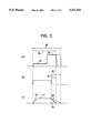
- FIG. 2 is an explanatory drawing showing the relationship among welding current, lift coil energization and lift movement.
- a stud welding machine 1 of the present invention has a welding gun 6 having a collet 3 to hold a stud 2 at the end thereof.
- a lift coil 5 is provided to lift the stud 2 held by the collet 3.
- a power source 7 connected to the welding gun supplies predetermined amounts of power across the stud 2 and a base material 4 to which stud 2 is to be welded.
- a control device 8 is connected to the power source 7 and the welding gun 6. The control device 8 controls the electric power supplied from the power source 7 to the welding gun to produce a pilot arc and a subsequent main arc across the stud 2 and the base material 4.
- the stud welding machine 1 is of the drawn arc type which lifts a stud simultaneously with applying a voltage to the stud brought in contact with a base material, producing an arc discharge on the surfaces to be welded between the base material and the stud, and brings the stud into press-contact with the base material at a time when the temperature is suitable for welding.
- the control device 8 is provided with a voltage detector 9 which detects the voltage across the stud 2 and the base material 4 and outputs a signal indicating that the stud is in press-contact with the base material.
- Device 8 also includes a current detector 10 which detects the welding current supplied from the power source 7 to the welding gun 6. Detection signals output from these detectors 9 and 10 are sent to a sequence controller 11 to control a series of actions necessary for the drawn arc type of stud welding machine.
- the power source 7 is a chopper type high frequency source and is controlled by the PWM system. Accordingly, the power source 7 is controlled by the sequence controller 11 so that it's electric current is suitable for producing a pilot arc and a subsequent main arc while always keeping the voltage constant.
- outputs from the current detector 10 are input in the sequence controller 11. Based on these inputs, controller 11 limits the current during the pilot arc and allows a larger current to flow during the main arc.
- Outputs from the voltage detector 9 indicate a period in which the stud 2 is separated from the base material 4 and a period in which the stud 2 is in press-contact with the base material 4. These outputs are also input into the sequence controller 11.
- Control outputs from the sequence controller 11 are input to a lift coil controller 12 to energize and de-energize the lift coil 5.
- the lift coil controller 12 energizes the lift coil 5 to lift the collet 3 of the welding gun 6 against the force of a spring contained therein. Due to this lift, the stud 2 is raised to a predetermined height from the base material 4 while a pilot arc and subsequently a main arc are produced. After a predetermined time passes and the end of the stud and a part of the base material are molten, the lift coil controller de-energizes the lift coil 5 and this de-energization allows the spring force of the integral spring to lower the collet 3.
- a pilot arc current 14 and a main arc current 15 of the relative sizes shown by the waveform (A) of FIG. 2 are supplied one by one from the power source 7 to the stud 2 and the base material 4. Both are constant-voltage currents.
- the lift coil controller 12 energizes the lift coil 5 from the beginning of the pilot arc until the temperature of the stud and the base material melted by the main arc reaches a predetermined value.
- the stud 2 is raised from the base material 4 gradually to a predetermined height as shown by a slope 16 of the waveform (C) of FIG.
- the voltage across the two members lowers to zero, in response to which the voltage detector 9 outputs a press-contact signal.
- the sequence controller 11 receives the press-contact signal from the voltage detector 9, the sequence controller 11 sends a control signal to the power source 7 to stop the power supply.
- the electric current is cut off after the press-contact of the stud with the base material is confirmed, whereby differences in timing between the press-contact and the supply of power is fully prevented.
- the descent of the collet caused by de-energization of the lift coil 5, or the resultant descent of the stud 2 to the base material 4 sometimes fails to correspond to the slope 19, as shown by a broken line in FIG. 2 (C), because of changes with the passage of time of the sliding resistance of the portion of the collet moved by the lift means, variance among adjusted distances of the welding gun 6, and the like.
- This increases the time of descent 21 to a time of descent 22 in FIG. 2 (B) to prolong welding time 23 to welding time 24 in FIG. 2 (A), giving rise to the possibility of low quality welding.
- the control device 8 is provided with a descent time counter 26 to measure descent time from the de-energization of the lift coil 5 to contact of the stud 2 with the base material 4.
- a lift coil energization signal is input to the descent time counter 26 from the lift coil controller 12, and other inputs are connected to the stud 2 and the base material 4 to detect contact of the two members. Therefore, the descent time counter 26 can measure a period from the de-energization of the lift coil 5 to the press-contact of the stud 2 with the base material 4, namely, the time of descent.
- Measured times of descent are input to an average value calculator 27 provided in the control device 8.
- the average value calculator 27 operates to average, for example, ten measured values.
- Calculator 27 may be arranged to exclude measurement values out of an allowable range previously set. It is preferable to arrange that calculation is made every time the base material is replaced and the order of welding is changed. According to the present invention, outputs from the average value calculator 27, i.e., averaged times of descent, are input to the sequence controller 11, which is given the function to adjust the timing of de-energizing the lift coil 5 by using values averaged by the average value calculator 27.
- the sequence controller 11 adjusts the timing of de-energizing the lift coil 5.
- the timing of de-energization after adjustment is fed to the lift coil controller 12, which de-energizes the lift coil 5 so as to keep the welding time unchanged. In this way, a constant welding time is maintained.
- the control device is provided with means to measure descent time from de-energization of the lift means to press-contact of the stud with the base material, means to average such time values measured N times, and means to adjust the timing of de-energizing the lift means by using average values. Therefore, the welding time is reliability kept constant, thereby maintaining the quality of welding a high level.
Abstract
Description
Claims (1)
Applications Claiming Priority (2)
| Application Number | Priority Date | Filing Date | Title |
|---|---|---|---|
| JP1992050287U JP2596517Y2 (en) | 1992-07-17 | 1992-07-17 | Stud welding machine control device |
| JP4-50287[U] | 1992-07-17 |
Publications (1)
| Publication Number | Publication Date |
|---|---|
| US5317123A true US5317123A (en) | 1994-05-31 |
Family
ID=12854707
Family Applications (1)
| Application Number | Title | Priority Date | Filing Date |
|---|---|---|---|
| US08/091,837 Expired - Lifetime US5317123A (en) | 1992-07-17 | 1993-07-13 | Controller for a stud welding machine |
Country Status (2)
| Country | Link |
|---|---|
| US (1) | US5317123A (en) |
| JP (1) | JP2596517Y2 (en) |
Cited By (27)
| Publication number | Priority date | Publication date | Assignee | Title |
|---|---|---|---|---|
| US5406044A (en) * | 1994-04-20 | 1995-04-11 | Eaton Corporation | Displacement monitoring system for stud welding |
| US5938945A (en) * | 1995-07-05 | 1999-08-17 | Emhart Inc. | Method of welding weld studs to a workpiece |
| US5977506A (en) * | 1994-10-03 | 1999-11-02 | Emhart Inc. | Welding method for the connection of a component to a workpiece, and a device for carrying out the method |
| US6011234A (en) * | 1994-08-16 | 2000-01-04 | Kirchner; Eduard | Device for welding together at least two parts and method of using the device |
| EP1060822A2 (en) * | 1999-06-16 | 2000-12-20 | Udo Prof. Dr. Franz | Method for welding elements with a workpiece |
| US20030019847A1 (en) * | 2000-01-14 | 2003-01-30 | Schmitt Klaus Gisbert | Method and device for multiple stage arc-welding |
| WO2003011510A2 (en) * | 2001-07-23 | 2003-02-13 | Newfrey Llc | Method for short-cycle arc welding and a short-cycle arc welding system |
| WO2003020466A1 (en) * | 2001-09-03 | 2003-03-13 | Newfrey Llc | Short-time arc welding system and associated method |
| EP1375045A1 (en) * | 2002-06-26 | 2004-01-02 | Newfrey LLC | Short-time arc welding system and associated method |
| US20040008644A1 (en) * | 1999-10-07 | 2004-01-15 | Jack Holtzman | Method and apparatus for predicting favored supplemental channel transmission slots using transmission power measurements of a fundamental channel |
| US20040037634A1 (en) * | 2002-05-16 | 2004-02-26 | Manfred Muller | Joining system head, joining system, and method of feeding and joining elements |
| US6762392B1 (en) | 1999-06-05 | 2004-07-13 | Newfrey Llc | Lift-and-strike welding process with cleaning stage |
| US20040169017A1 (en) * | 2001-07-04 | 2004-09-02 | Kanji Sakoda | Method and device for welding an aluminum-based stud |
| US6838634B2 (en) | 2002-05-03 | 2005-01-04 | Newfrey Llc | Device for welding metal elements to structural parts |
| EP1570940A1 (en) * | 2004-03-01 | 2005-09-07 | Newfrey LLC | Arc stud welding device and method |
| US20060151442A1 (en) * | 2002-05-16 | 2006-07-13 | Schmitt Klaus G | Joining system head, joining system, and method of feeding and joining elements |
| US20060186092A1 (en) * | 2003-07-17 | 2006-08-24 | Alexander Schug | Joining device |
| US20060280160A1 (en) * | 1997-11-03 | 2006-12-14 | Roberto Padovani | Method and apparatus for high rate packet data transmission |
| US20070267392A1 (en) * | 2006-05-22 | 2007-11-22 | Newfrey Llc | Welding workpiece movement sensing system |
| US20070295699A1 (en) * | 2006-06-27 | 2007-12-27 | Mark Ulrich | Multi-level welding position controller |
| US8064409B1 (en) | 1999-08-25 | 2011-11-22 | Qualcomm Incorporated | Method and apparatus using a multi-carrier forward link in a wireless communication system |
| US20130062327A1 (en) * | 2011-09-13 | 2013-03-14 | Nelson Stud Welding, Inc. | Two-stage switch-mode power supply for drawn-arc stud welding |
| US8811200B2 (en) | 2009-09-22 | 2014-08-19 | Qualcomm Incorporated | Physical layer metrics to support adaptive station-dependent channel state information feedback rate in multi-user communication systems |
| US9107109B2 (en) | 2000-10-25 | 2015-08-11 | Qualcomm Incorporated | Method and apparatus for determining a data rate in a high rate packet data wireless communications system |
| US9118387B2 (en) | 1997-11-03 | 2015-08-25 | Qualcomm Incorporated | Pilot reference transmission for a wireless communication system |
| CN105215511A (en) * | 2015-09-24 | 2016-01-06 | 珠海市持久电子科技有限公司 | A kind of automobile aluminum vehicle body quick repairing machine |
| US9426821B2 (en) | 2000-10-25 | 2016-08-23 | Qualcomm Incorporated | Method and apparatus for high rate packet data and low delay data transmissions |
Families Citing this family (1)
| Publication number | Priority date | Publication date | Assignee | Title |
|---|---|---|---|---|
| CN104708185A (en) * | 2015-03-05 | 2015-06-17 | 奇瑞汽车股份有限公司 | Stud welding machine system |
Citations (3)
| Publication number | Priority date | Publication date | Assignee | Title |
|---|---|---|---|---|
| US4297560A (en) * | 1979-02-26 | 1981-10-27 | Usm Corporation | Process and apparatus for testing arc stud welding guns |
| US4988842A (en) * | 1990-02-12 | 1991-01-29 | Emhart Inc. | Stud welding system |
| US5030815A (en) * | 1990-11-28 | 1991-07-09 | Trw Inc. | Apparatus for controlling a welding tool |
-
1992
- 1992-07-17 JP JP1992050287U patent/JP2596517Y2/en not_active Expired - Fee Related
-
1993
- 1993-07-13 US US08/091,837 patent/US5317123A/en not_active Expired - Lifetime
Patent Citations (3)
| Publication number | Priority date | Publication date | Assignee | Title |
|---|---|---|---|---|
| US4297560A (en) * | 1979-02-26 | 1981-10-27 | Usm Corporation | Process and apparatus for testing arc stud welding guns |
| US4988842A (en) * | 1990-02-12 | 1991-01-29 | Emhart Inc. | Stud welding system |
| US5030815A (en) * | 1990-11-28 | 1991-07-09 | Trw Inc. | Apparatus for controlling a welding tool |
Cited By (70)
| Publication number | Priority date | Publication date | Assignee | Title |
|---|---|---|---|---|
| US5406044A (en) * | 1994-04-20 | 1995-04-11 | Eaton Corporation | Displacement monitoring system for stud welding |
| US6011234A (en) * | 1994-08-16 | 2000-01-04 | Kirchner; Eduard | Device for welding together at least two parts and method of using the device |
| US5977506A (en) * | 1994-10-03 | 1999-11-02 | Emhart Inc. | Welding method for the connection of a component to a workpiece, and a device for carrying out the method |
| US5938945A (en) * | 1995-07-05 | 1999-08-17 | Emhart Inc. | Method of welding weld studs to a workpiece |
| US8005042B2 (en) | 1997-11-03 | 2011-08-23 | Qualcomm Incorporated | Method and apparatus for high rate packet data transmission |
| US7995531B2 (en) | 1997-11-03 | 2011-08-09 | Qualcomm Incorporated | Method and apparatus for high rate packet data transmission |
| US9124344B2 (en) | 1997-11-03 | 2015-09-01 | Qualcomm Incorporated | Pilot reference transmission for a wireless communication system |
| US9118387B2 (en) | 1997-11-03 | 2015-08-25 | Qualcomm Incorporated | Pilot reference transmission for a wireless communication system |
| US9001735B2 (en) | 1997-11-03 | 2015-04-07 | Qualcomm Incorporated | Method and apparatus for high rate packet data transmission |
| US8351372B2 (en) | 1997-11-03 | 2013-01-08 | Qualcomm Incorporated | Method and apparatus for high rate packet data transmission |
| US8311027B2 (en) | 1997-11-03 | 2012-11-13 | Qualcomm Incorporated | Method and apparatus for high rate packet data transmission |
| US20070025269A1 (en) * | 1997-11-03 | 2007-02-01 | Roberto Padovani | Method and apparatus for high rate packet data transmission |
| US8189540B2 (en) | 1997-11-03 | 2012-05-29 | Qualcomm Incorporated | Method and apparatus for high rate packet data transmission |
| US8089924B2 (en) | 1997-11-03 | 2012-01-03 | Qualcomm Incorporated | Method and apparatus for high rate packet data transmission |
| US20070025319A1 (en) * | 1997-11-03 | 2007-02-01 | Roberto Padovani | Method and apparatus for high rate packet data transmission |
| US8077655B2 (en) | 1997-11-03 | 2011-12-13 | Qualcomm Incorporated | Method and apparatus for high rate packet data transmission |
| US20070019567A1 (en) * | 1997-11-03 | 2007-01-25 | Roberto Padovani | Method and apparatus for high rate packet data transmission |
| US20070019608A1 (en) * | 1997-11-03 | 2007-01-25 | Roberto Padovani | Method and apparatus for high rate packet data transmission |
| US20060280160A1 (en) * | 1997-11-03 | 2006-12-14 | Roberto Padovani | Method and apparatus for high rate packet data transmission |
| US20070025320A1 (en) * | 1997-11-03 | 2007-02-01 | Roberto Padovani | Method and apparatus for high rate packet data transmission |
| US7848283B2 (en) | 1997-11-03 | 2010-12-07 | Qualcomm Incorporated | Method and apparatus for high rate packet data transmission |
| US7848284B2 (en) | 1997-11-03 | 2010-12-07 | Qualcomm Incorporated | Method and apparatus for high rate packet data transmission |
| US7848285B2 (en) | 1997-11-03 | 2010-12-07 | Qualcomm Incorporated | Method and apparatus for high rate packet data transmission |
| US7848282B2 (en) | 1997-11-03 | 2010-12-07 | Qualcomm Incorporated | Method and apparatus for high rate packet data transmission |
| US20090310588A1 (en) * | 1997-11-03 | 2009-12-17 | Qualcomm Incorporated | Method and apparatus for high rate packet data transmission |
| US20070025268A1 (en) * | 1997-11-03 | 2007-02-01 | Roberto Padovani | Method and apparatus for high rate packet data transmission |
| US20070025260A1 (en) * | 1997-11-03 | 2007-02-01 | Roberto Padovani | Method and apparatus for high rate packet data transmission |
| US6762392B1 (en) | 1999-06-05 | 2004-07-13 | Newfrey Llc | Lift-and-strike welding process with cleaning stage |
| EP1060822A3 (en) * | 1999-06-16 | 2002-09-11 | Udo Prof. Dr. Franz | Method for welding elements with a workpiece |
| EP1060822A2 (en) * | 1999-06-16 | 2000-12-20 | Udo Prof. Dr. Franz | Method for welding elements with a workpiece |
| US8064409B1 (en) | 1999-08-25 | 2011-11-22 | Qualcomm Incorporated | Method and apparatus using a multi-carrier forward link in a wireless communication system |
| US8068453B2 (en) | 1999-10-07 | 2011-11-29 | Qualcomm Incorporated | Method and apparatus for predicting favored supplemental channel transmission slots using transmission power measurements of a fundamental channel |
| US20040008644A1 (en) * | 1999-10-07 | 2004-01-15 | Jack Holtzman | Method and apparatus for predicting favored supplemental channel transmission slots using transmission power measurements of a fundamental channel |
| US6815631B2 (en) | 2000-01-14 | 2004-11-09 | Newfrey Llc | Method and device for multiple stage arc-welding |
| US20030019847A1 (en) * | 2000-01-14 | 2003-01-30 | Schmitt Klaus Gisbert | Method and device for multiple stage arc-welding |
| US9426821B2 (en) | 2000-10-25 | 2016-08-23 | Qualcomm Incorporated | Method and apparatus for high rate packet data and low delay data transmissions |
| US9107109B2 (en) | 2000-10-25 | 2015-08-11 | Qualcomm Incorporated | Method and apparatus for determining a data rate in a high rate packet data wireless communications system |
| US20040169017A1 (en) * | 2001-07-04 | 2004-09-02 | Kanji Sakoda | Method and device for welding an aluminum-based stud |
| US7176401B2 (en) | 2001-07-04 | 2007-02-13 | Newfrey Llc | Method and device for welding an aluminum-based stud |
| WO2003011510A2 (en) * | 2001-07-23 | 2003-02-13 | Newfrey Llc | Method for short-cycle arc welding and a short-cycle arc welding system |
| US7301119B2 (en) | 2001-07-23 | 2007-11-27 | Newfrey Llc | Process for short-time arc-welding and short-time arc-welding system |
| WO2003011510A3 (en) * | 2001-07-23 | 2003-09-18 | Newfrey Llc | Method for short-cycle arc welding and a short-cycle arc welding system |
| US20040182827A1 (en) * | 2001-07-23 | 2004-09-23 | Wolfgang Schmidt | Process for short-time arc welding and short-time arc welding system |
| US7279653B2 (en) | 2001-07-23 | 2007-10-09 | Newfrey Llc | Process for short-time arc-welding and short-time arc-welding system |
| US20060124608A1 (en) * | 2001-07-23 | 2006-06-15 | Wolfgang Schmidt | Process for short-time arc-welding and short-time arc-welding system |
| US20060124609A1 (en) * | 2001-07-23 | 2006-06-15 | Wolfgang Schmidt | Process for short-time arc-welding and short-time arc-welding system |
| US7045736B2 (en) * | 2001-07-23 | 2006-05-16 | Newfrey Llc | Process for short-time arc welding and short-time arc welding system |
| WO2003020466A1 (en) * | 2001-09-03 | 2003-03-13 | Newfrey Llc | Short-time arc welding system and associated method |
| US6838634B2 (en) | 2002-05-03 | 2005-01-04 | Newfrey Llc | Device for welding metal elements to structural parts |
| US7518084B2 (en) | 2002-05-16 | 2009-04-14 | Newfrey Llc | Joining system head, joining system, and method of feeding and joining elements |
| US20040037634A1 (en) * | 2002-05-16 | 2004-02-26 | Manfred Muller | Joining system head, joining system, and method of feeding and joining elements |
| US7291802B2 (en) | 2002-05-16 | 2007-11-06 | Newfrey Llc | Joining system head, joining system, and method of feeding and joining elements |
| US20060151442A1 (en) * | 2002-05-16 | 2006-07-13 | Schmitt Klaus G | Joining system head, joining system, and method of feeding and joining elements |
| US8653402B2 (en) | 2002-05-16 | 2014-02-18 | Newfrey Llc | Joining system head, joining system, and method of feeding and joining elements |
| US20070251923A1 (en) * | 2002-05-16 | 2007-11-01 | Newfrey Llc | Joining system head, joining system, and method of feeding and joining elements |
| US20040056005A1 (en) * | 2002-06-26 | 2004-03-25 | Jorg Willershausen | Device and method for short cycle arc welding |
| EP1375045A1 (en) * | 2002-06-26 | 2004-01-02 | Newfrey LLC | Short-time arc welding system and associated method |
| US7109434B2 (en) | 2002-06-26 | 2006-09-19 | Newfrey Llc | Device and method for short cycle arc welding |
| US7521647B2 (en) | 2003-07-17 | 2009-04-21 | Newfrey Llc | Joining device |
| US20060186092A1 (en) * | 2003-07-17 | 2006-08-24 | Alexander Schug | Joining device |
| US20050218119A1 (en) * | 2004-03-01 | 2005-10-06 | Newfrey Llc | Arc stud welding device and method |
| US7141753B2 (en) | 2004-03-01 | 2006-11-28 | Newfrey Llc | Arc stud welding device and method |
| EP1570940A1 (en) * | 2004-03-01 | 2005-09-07 | Newfrey LLC | Arc stud welding device and method |
| US20070267392A1 (en) * | 2006-05-22 | 2007-11-22 | Newfrey Llc | Welding workpiece movement sensing system |
| US20070295699A1 (en) * | 2006-06-27 | 2007-12-27 | Mark Ulrich | Multi-level welding position controller |
| US8811200B2 (en) | 2009-09-22 | 2014-08-19 | Qualcomm Incorporated | Physical layer metrics to support adaptive station-dependent channel state information feedback rate in multi-user communication systems |
| US20130062327A1 (en) * | 2011-09-13 | 2013-03-14 | Nelson Stud Welding, Inc. | Two-stage switch-mode power supply for drawn-arc stud welding |
| EP2849911A4 (en) * | 2011-09-13 | 2016-03-23 | Nelson Stud Welding Inc | Two-stage switch-mode power supply for drawn-arc stud welding |
| US10279415B2 (en) * | 2011-09-13 | 2019-05-07 | Nelson Stud Welding, Inc. | Two-stage switch-mode power supply for drawn-arc stud welding |
| CN105215511A (en) * | 2015-09-24 | 2016-01-06 | 珠海市持久电子科技有限公司 | A kind of automobile aluminum vehicle body quick repairing machine |
Also Published As
| Publication number | Publication date |
|---|---|
| JPH0648967U (en) | 1994-07-05 |
| JP2596517Y2 (en) | 1999-06-14 |
Similar Documents
| Publication | Publication Date | Title |
|---|---|---|
| US5317123A (en) | Controller for a stud welding machine | |
| US4170727A (en) | Thermal torch height acquisition circuit | |
| US4861960A (en) | Real time adaptive control for resistance spot welding process | |
| US4788412A (en) | Method of control and apparatus for hot-wire welding | |
| US4963707A (en) | Resistance welding control system | |
| EP0774317A1 (en) | Pulsed arc welding method and apparatus | |
| US4797529A (en) | Stud welding apparatus | |
| JPH051107B2 (en) | ||
| US4877941A (en) | Power supply system for consumable electrode arc welding and method of controlling the same | |
| JPS649911B2 (en) | ||
| JPH06155025A (en) | Welding current generator for pulse arc welding | |
| CA1187562A (en) | Welding method and apparatus | |
| US4408114A (en) | Resistance welding with pressure control in response to deviation between welding voltage and time varying reference values therefor | |
| ES2002744A6 (en) | Method and arrangement for controlling a resistance-welding machine. | |
| US3562487A (en) | Systems for generating a constant current within limited voltage ranges | |
| US4849601A (en) | Current-loop feedback of spot welding machines | |
| JPS5840241A (en) | Electric controller | |
| US5313045A (en) | Method and apparatus for reducing energy consumption and minimizing martensite formations when joining a connecting piece of metal with a metal surface by pin brazing | |
| CA2040132C (en) | Process and circuit for regulating welding current and power as a function of welding speed | |
| CA2024886C (en) | Welding process and apparatus | |
| US6388233B1 (en) | Method and apparatus for arc welding with melting electrode | |
| JPH09182961A (en) | Carbon dioxide gas shielded pulsed arc welding method | |
| JPS5913584A (en) | Method and device for controlling resistance welding | |
| US2671869A (en) | Automatic arc welding method and apparatus | |
| JPS5844981A (en) | Automatic regulator for welding current |
Legal Events
| Date | Code | Title | Description |
|---|---|---|---|
| AS | Assignment |
Owner name: EMHART INC., DELAWARE Free format text: ASSIGNMENT OF ASSIGNORS INTEREST;ASSIGNOR:ITO, HIROSHI;REEL/FRAME:006696/0136 Effective date: 19930902 |
|
| STPP | Information on status: patent application and granting procedure in general |
Free format text: APPLICATION UNDERGOING PREEXAM PROCESSING |
|
| FPAY | Fee payment |
Year of fee payment: 4 |
|
| FPAY | Fee payment |
Year of fee payment: 8 |
|
| AS | Assignment |
Owner name: EMHART LLC, DELAWARE Free format text: CHANGE OF NAME;ASSIGNOR:EMHART INC.;REEL/FRAME:013036/0919 Effective date: 20011029 |
|
| AS | Assignment |
Owner name: NEWFREY LLC, DELAWARE Free format text: CHANGE OF NAME;ASSIGNOR:EMHART LLC;REEL/FRAME:013516/0757 Effective date: 20021030 |
|
| FPAY | Fee payment |
Year of fee payment: 12 |