US5321318A - Stray current neutralizing method and device - Google Patents
Stray current neutralizing method and device Download PDFInfo
- Publication number
- US5321318A US5321318A US07/888,140 US88814092A US5321318A US 5321318 A US5321318 A US 5321318A US 88814092 A US88814092 A US 88814092A US 5321318 A US5321318 A US 5321318A
- Authority
- US
- United States
- Prior art keywords
- current
- saturable reactor
- terminal
- stray current
- stray
- Prior art date
- Legal status (The legal status is an assumption and is not a legal conclusion. Google has not performed a legal analysis and makes no representation as to the accuracy of the status listed.)
- Expired - Lifetime
Links
Images

Classifications
-
- H—ELECTRICITY
- H02—GENERATION; CONVERSION OR DISTRIBUTION OF ELECTRIC POWER
- H02H—EMERGENCY PROTECTIVE CIRCUIT ARRANGEMENTS
- H02H3/00—Emergency protective circuit arrangements for automatic disconnection directly responsive to an undesired change from normal electric working condition with or without subsequent reconnection ; integrated protection
- H02H3/14—Emergency protective circuit arrangements for automatic disconnection directly responsive to an undesired change from normal electric working condition with or without subsequent reconnection ; integrated protection responsive to occurrence of voltage on parts normally at earth potential
Definitions
- the present invention relates to a stray current neutralizing method and device capable of neutralizing a particular phenomenon of the tingle voltages, that is the bypass currents that can greatly affect the health of a livestock.
- perception threshold 1--3 mA (duration of 1 sec);
- fibrillation current threshold 30 mA and more (duration of 1 sec).
- cows will refuse to give their milk and to enter in the cowshed. They may also paw the ground and kick the milker. In the most critical situations, the cows present problems of mastitis, of reproduction, of leucocyte, etc.
- Pigs can present similar symptoms; cases of cannibalism and mastitis, and problems of diarrhoea, of temperature and of constipation can be found. In the most critical cases, the dead-rate of the little pigs may considerably increase.
- stray current may cause luxation of the vertebral column of the fish and will greatly stress the fish to cause repeated furunculosis epidemic.
- An object of the present invention is therefore to neutralize stray current that can flow through the body of an animal(s) bred or kept in a farm building.
- a device for neutralizing alternating stray current flowing through a ground return circuit in the proximity of an animal susceptible to be affected by the stray current comprising:
- means for producing a signal representative of the sensed stray current means for generating, in response to the current representative signal, an alternating compensatory current having an amplitude substantially equal to the amplitude of the sensed stray current and being out of phase with respect to the stray current by an angle substantially equal to 180°;
- the stray current and the compensatory current are flowing in the same circuit, they add together and substantially cancel each other. The stray current is then substantially cancelled and can no longer affect the animal.
- the present invention also relates to a method for neutralizing alternating stray current flowing through a ground return circuit in the proximity of an animal susceptible to be affected by this stray current, comprising the steps of:
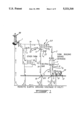
- FIG. 1 is a schematic diagram illustrating the origin of stray current in a medium-voltage distribution network
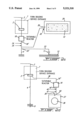
- FIG. 2a is a schematic diagram illustrating a first method of connecting a stray current neutralizing device in accordance with the present invention with the electric installation of a farm building;
- FIG. 2b is a schematic diagram illustrating a second method of connecting a stray current neutralizing device in accordance with the present invention with the electric installation of a farm building;
- FIG. 2c is a schematic diagram illustrating a third method of connecting a stray current neutralizing device in accordance with the present invention with the electric installation of a farm building;
- FIG. 2d is a schematic diagram illustrating a fourth method of connecting a stray current neutralizing device in accordance with the present invention with the electric installation of a farm building;
- FIG. 2e is a schematic diagram illustrating a fifth method of connecting a stray current neutralizing device in accordance with the present invention with the electric installation of a farm building;
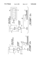
- FIG. 3 is a block diagram of the electronic circuit of a stray current neutralizing device in accordance with the present invention.
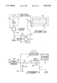
- FIG. 4 shows the output connections of the electronic circuit of FIG. 3 to the electric installation of the farm building.
- a tingle voltage is a potential difference existing between two points susceptible to be contacted simultaneously by an animal to cause a flow of current through the animal's body.
- a tingle voltage can also be defined as a potential difference between two points caused by a flow of current through the body of an animal.
- a tingle voltage can produce a flow of current both (a) through the body of the animal from the concrete floor toward metallic structures contacted by the animal (touch voltage circuit), and (b) through the animal's body from one paw to the other (step voltage circuit).
- the structure of the electric distribution networks such as 1 causes the flow of a small portion of the primary supply alternating current toward the ground, and this current tends to return to its source (substation 99) through the earth.
- the current I 3 flowing through the primary neutral conductor 14 of the utility's medium-voltage network 1 creates a voltage drop in that conductor 14.
- a portion I 4 of the primary current I 5 flowing through the primary winding of the farm transformer 6 therefore tends to return to the substation 99 through the earth.
- the grounding connections such as 15 and 16 of the primary neutral conductor 14 have a certain resistance, a potential with respect to the earth ground (0 volt) appears on the primary neutral 17 of transformer 6.
- the Ohm's law predicts this behavior of a medium-voltage network; the potential on the primary neutral 17 cannot be equal to 0 if the resistance of the primary neutral conductor 14 is not equal to 0 or if the resistance of the grounding connections such as 15 and 16 is not equal to 0. As the two latter conditions cannot be reached, it is impossible to cancel the voltage on the primary neutral 17.
- the intensity I 6 of the current flowing in the grounding conductor 19 and the ground rod 20 is of course function of the potential of the primary neutral 17 and the resistance of the ground connection 16. The same applies for the other ground connections such as 15.
- the potential on the primary neutral 17 is transmitted to the secondary neutral 22 of the farm transformer as these two neutrals are interconnected at the transformer 6 through a conductor 23.
- the voltage on the primary neutral 17 therefore causes a flow of current I 7 through the conductor 23, the neutral conductor 3, the neutral bar 2, the grounding conductor 4 and the ground rod 9, this current I 7 increasing the amplitude of the ground current I 1 .
- the voltage on the primary neutral also causes a flow of current I 8 in the circuit formed by the conductor 23, the neutral conductor 3, the grounding conductor 8, and the metallic structures such as the stalls 10 and the drinking troughs 11, the current I 8 raising the value of the ground current I 2 .
- bypass currents such as I 1 , I 2 and I 6 add and flow in the soil toward the substation 99. Due to the complex nature of the soil, the distribution of the current at the surface of the ground is not uniform. This stray current, flowing through the soil, tends to raise toward the primary neutral of the utility and is therefore attracted by the high humidity level and the alkaline nature of the concrete floor 12 of the farm building.
- the stray current will flow through the body of the cow 24 or other animal (touch or step circuit) to reach the metallic structures (stalls 10, drinking troughs 11, manure remover (not shown), etc.), and then will flow toward the grounding and neutral conductors (see for example 3 and 8 in FIG. 1).
- An electric service entrance 7 for a farm building usually comprises, as illustrated for example in FIG. 2a, a saturable reactor (or saturable filter) 18 installed on the distribution board of that service entrance 7, between the neutral bar 2 and the grounding network of the farm building.
- a saturable reactor or saturable filter 18 installed on the distribution board of that service entrance 7, between the neutral bar 2 and the grounding network of the farm building.
- the saturable reactor 18 is a static, magnetic-core reactor, similar to a transformer but having a variable impedance. More specifically, the saturable reactor will present, under normal conditions, a high resistance to current flow of low intensity from the neutral bar 2 to the grounding network (including for example grounding conductor 4, ground rod 9, grounding conductor 25, and metallic structures such as the stalls 10 and the drinking troughs 11, etc.) to thereby limit such current. However, under overload (overvoltage) conditions, the resistance of the reactor 18 will decrease to a very low value, to enable flowing of high current.
- the reactor 18 will prevent tingle voltages from the other buildings of the same farm and of neighbour farms to enter in the grounding network of the farm building of concern. Therefore, this reactor 18 will not eliminate the tingle voltage but will prevent it to affect the animal(s).
- the saturable reactor 18 will however enable low intensity alternating current to flow from ground bar 4 to the neutral bar 2.
- an insulated copper conductor (#6 AWG) 25 is used to interconnect all the metallic structures (stalls 10, drinking troughs 11, etc.). Upon installation of this insulated copper conductor, it is important to create no internal loops between the different metallic structures.
- One end 25' of the insulated copper conductor 25 is connected to one terminal 18' of the saturable reactor 18, to thereby establish a ground return circuit (soil, concrete floor 12, animal(s), metallic structures, conductor 25, saturable reactor 18, neutral conductor 3, etc.) conducting the alternating stray current flowing through the cows or other animals toward and through this reactor 18.
- a ground return circuit soil, concrete floor 12, animal(s), metallic structures, conductor 25, saturable reactor 18, neutral conductor 3, etc.
- a current transformer 100 (FIG. 3) will sense the alternating stray current at point 26, and an alternating compensatory current having the same amplitude as the sensed stray current, but being out of phase by an angle of 180° with respect to the latter current will be injected in the ground return circuit at point 27, situated between point 26 and the reactor's terminal 18'. The stray current flowing through the reactor 18 will then be, if not cancelled, reduced to the order of the milliampere.
- This method will eliminate any touch current circuit, i.e. any circuit in which a current flows through the body of an animal from the concrete floor to the metallic structures.
- an insulated copper conductor (#6 AWG) 28 interconnects all theses metallic structures. It is however important that the conductor 28 creates no internal loops in the different metallic structures.
- the conductor 28 will establish a ground return circuit (soil, concrete floor 12, metallic structures, grounding conductor 28, saturable reactor 18, neutral conductor 3, etc.) for the stray current.
- a tinned conductor 29 is buried under the surface of the ground at a deepness varying between 6 and 12 inches. This conductor 29 is associated with a grounding rod (not shown) in view of establishing a very low impedance network.
- the conductor 29 completely encircles the concrete floor 12 of the farm building, and is interrupted at only one point 30.
- the current transformer 100 is mounted at point 31, that is at the terminal 18' of the saturable reactor 18, and the alternating compensatory current is injected at one end 32 of the tinned conductor 29, close to point 30.
- the compensatory current injected in the ground return circuit through the conductor 29 at point 32 will substantially cancel the stray current reaching the concrete floor 12 of the farm building and susceptible to flow through the animal(s).
- an insulated copper conductor (#6 AWG) 33 is used to interconnect all the metallic structures such as the drinking troughs 11 in the farm building;
- the conductor 33 has one end 33' connected to the terminal 18' of the saturable reactor 18 to establish a ground return circuit (soil, concrete floor 12, metallic structures, grounding conductor 33, conductor 29, saturable reactor 18, neutral conductor 3, etc.) for the stray current;
- the tinned copper conductor 29 is buried under the ground surface at a deepness between 6 and 12 inches and is associated with a ground rod (not shown) in view of establishing a very low impedance network.
- the conductor 29 encircles completely the concrete floor 12 of the farm building, and is interrupted at point 30.
- the current transformer 100 is mounted at point 34 on the terminal 18' of the saturable reactor 18, and the compensatory current is injected in the ground return circuit at point 35, adjacent point 34 on the side opposite to the reactor 18.
- the problem overcome is the step current circuit allowing current to flow through the body of the animal from one paw to the other.
- the grounding conductor 4 connects directly the neutral bar 2 to the ground electrode 9;
- a conductor 36 interconnects the neutral bar 2 and the terminal 18'' of the saturable reactor 18;
- a tinned copper conductor 37 encircles the fish breeding basin 38, the conductor 37 being lowered in the water or soil encircling the basin 38.
- the conductor 37 is interrupted at point 39;
- one end 40 of the conductor 37 is connected to the terminal 18' of the saturable reactor 18 to establish a ground return circuit (soil or water, conductor 37, saturable reactor 18, grounding conductor 36, neutral conductor 3, etc.) for the stray current; and
- the current transformer 100 is mounted at point 41 on the terminal 18' between the saturable reactor 18 and the conductor 37, and the compensatory current is injected in the ground return circuit at point 42, adjacent point 41 and situated between point 41 and the saturable reactor 18.
- a tinned copper conductor 43 is buried under the ground surface at a deepness between 6 and 12 inches and is associated with a ground rod (not shown) in view of establishing a very low impedance network.
- the conductor 43 encircles completely the concrete floor 12 of the farm building, and is interrupted at point 44.
- one end 45 of the conductor 43 is connected to the terminal 18' of the saturable reactor 18 through a grounding conductor 46, another saturable reactor 47 and another grounding conductor 48 to establish a ground return circuit (soil, conductor 43, grounding conductor 46, saturable reactor 47, grounding conductor 48, saturable reactor 18, neutral conductor 3, etc.) for the stray current; and
- the current transformer 100 is mounted at point 49 on the terminal 47' of the saturable reactor 47, and the compensatory current is injected in the ground return circuit at point 50 on the terminal 47'' of the reactor 47.
- FIG. 2e The installation of FIG. 2e will eliminate any step current circuit.
- FIG. 3 is a block diagram of the electronic circuit of the stray current neutralizing device in accordance with the present invention.
- the alternating stray current is sensed through a current transformer 100 situated at one of the positions illustrated in FIGS. 2a-2d.
- a current transformer 100 situated at one of the positions illustrated in FIGS. 2a-2d.
- the use of a current transformer 100 is essential as, in accordance with the Canadian Code of Electricity, rupture of a grounding conductor to insert a current measuring equipment is forbidden.
- An alternating current representative signal 101 is produced at the secondary terminals of the current transformer 100 and applied to the input of a signal converter 102.
- This converter 102 includes a differential amplifier 103, having a voltage gain of 33, for amplifying the current representative signal 101.
- the amplified signal 104 at the output of the amplifier 103 is then filtered through a 1st-order low-pass filter 105 having a transition frequency of 360 Hz.
- the signal at the output of the filter 105 is then preamplified (130) with a gain of 10.
- An alternating current measurement signal 106 is obtained at the output of the preamplifier 130, which is also the output of the converter 102.
- the current measurement signal 106 is received and amplified by a proportional controller 107.
- the function of the controller 107 is to adjust t he overall gain of the amplification chain including the converter 102, the proportional controller 107, gain controller 108 and power amplifier 109, so that the overall gain of this chain can be adjusted to inject an alternating compensatory current having an amplitude equal to that of the stray current sensed through the transformer 100.
- the proportional controller 107 has a set point equal to "0" and a gain manually adjustable from 0 to 20 by means of a DIP switch and many potentiometers. This is the only adjustment susceptible to be carried out upon installation of the stray current neutralizing device.
- the alternating output signal 110 from the proportional controller 107 is supplied to the power amplifier 109 through a gain controller 108.
- the gain controller will transmit or not the signal 110 to the power amplifier 109.
- the gain controller 108 may be constructed from an analog multiplier having a first input receiving the signal 110 from the proportional controller 107 and a second input on which signal 112 is applied.
- the disturbance detector 111 comprises a first low-pass filter 114 having a transition frequency of 50 kHz, and a second high-pass filter 114' having a transition frequency of 3.8 kHz. Accordingly, the detector 111 will detect only disturbances produced by the power amplifier 109 and having a frequency situated between 3.5 and 50 kHz.
- the output of filter 114' is amplified (115) whereby disturbances of small amplitude can be detected, and rectified (116) to provide a DC signal 112 representative of the disturbance and compatible with the analog multiplier of the gain controller 108.
- the detector 111 filters (114 and 114'), amplifies (115) and rectifies (116) such disturbances to produce a DC signal 112 having an amplitude suitable to control the controller 108 so as to prevent the signal 110 to be applied to the input 117 of the power amplifier 109 during these disturbances.
- the power amplifier 109 amplifies the alternating output signal 117 from the gain controller 108.
- the gain of amplifier 109 is negative and equal to 31 whereby the current injected in the ground return circuit 113 is out of phase by an angle of 180° with respect to the stray current sensed by the current transformer 100.
- the overall gain of the amplification chain 102, 107, 108 and 109 is adjusted through the proportional controller so that the amplitude of the current injected by the power amplifier 109 has the same amplitude.
- the compensatory current injected in the ground return circuit 113 by the power amplifier 109 has the same amplitude as the sensed stray current, but is out of phase by an angle of 180° with respect to that stray current, theses stray and compensatory currents will add and cancel each other in the ground return circuit.
- the stray current will then, in not completely neutralized, substantially reduced in amplitude (amplitude of the order of the milliampere).
- a bipolar Zener diode (transient) 120 has its cathode connected to the output 118 of the power amplifier 109 and its anode connected to the ground 119 of the electronic circuit (ground of the power supply (not shown)). This ground 119 is itself connected to the neutral bar 2.
- the bipolar Zener diode 120 will cause a high current to flow through the fuse 121 when the amplitude of the voltage at the output 118 of the amplifier 109 becomes higher than a nominal value (22 volts). The power amplifier 109 is thereby protected against overvoltages.
- a fused 121 and a resistor 122 are connected in series between the output 118 of the power amplifier 109 and the ground return circuit.
- the resistor 122 will damp oscillations at very low frequencies (1 to 4 Hz).
- the fuse 121 is a fuse that melts slowly in response to an overcurrent condition. It will protect the stray current neutralizing device upon a short-circuit occurring on the grounding conductor such as 4. It will also limit the intensity of the output current from the power amplifier 109.
- a trigger circuit 123 (FIG. 3) converts the current measurement signal 106 from output of the converter 102 into a DC signal and compares this DC signal to a DC voltage reference 124.
- the reference 124 is adjusted to represent a maximum current on the output 118 of the power amplifier.
- a triggering signal 125 is transmitted to a relay through a delay circuit 127 and a latch circuit 128.
- the delay circuit 127 will delay transmission of any triggering signal 125 during a time period of 1 sec to prevent triggering of the relay upon occurrence of a signal 125 of short duration.
- the latch circuit will store the triggering signal 125 until a reset switch 129 is operated.
- the contacts 126' of the relay 126 are normally open contacts mounted between the output 118 of the power amplifier 109 and the ground return circuit 113.
- the coil (not shown) of the relay 126 is normally energized to close the normally open contacts 126' and connect the output 118 to the circuit 113.
- the coil of the relay 126 is deenergized to open these contacts; this condition persists until the reset switch 129 is depressed or otherwise operated as described above.
- the coil of the relay 126 will be deenergized to open the normally open contacts 126' and disconnect the output 118 of the power amplifier 109 from the ground return circuit.
Abstract
Description
Claims (19)
Applications Claiming Priority (2)
| Application Number | Priority Date | Filing Date | Title |
|---|---|---|---|
| CA2060673 | 1992-02-05 | ||
| CA002060673A CA2060673C (en) | 1992-02-05 | 1992-02-05 | Stray current neutralizing method and device |
Publications (1)
| Publication Number | Publication Date |
|---|---|
| US5321318A true US5321318A (en) | 1994-06-14 |
Family
ID=4149210
Family Applications (1)
| Application Number | Title | Priority Date | Filing Date |
|---|---|---|---|
| US07/888,140 Expired - Lifetime US5321318A (en) | 1992-02-05 | 1992-05-26 | Stray current neutralizing method and device |
Country Status (2)
| Country | Link |
|---|---|
| US (1) | US5321318A (en) |
| CA (1) | CA2060673C (en) |
Cited By (14)
| Publication number | Priority date | Publication date | Assignee | Title |
|---|---|---|---|---|
| EP0780960A1 (en) * | 1995-12-21 | 1997-06-25 | Mitsubishi Denki Kabushiki Kaisha | Electric leakage preventive apparatus and method |
| US5793591A (en) * | 1996-11-08 | 1998-08-11 | Meco Corporation | Stray voltage reduction device |
| US5818672A (en) * | 1997-08-25 | 1998-10-06 | Hilbe; Thomas C. | Ground loop current suppressor |
| US5825170A (en) * | 1997-01-24 | 1998-10-20 | Filtre-Expert | Magnetically coupled alternating stray current neutralizing method and system |
| US5869909A (en) * | 1997-05-08 | 1999-02-09 | ATT Corp--Lucent Technologies Inc | Active ground compensation |
| US6555934B2 (en) * | 2000-12-18 | 2003-04-29 | Ge Medical Systems Global Technology Company, Llc | Method and apparatus for control of large-area ground plane potentials |
| US20030189432A1 (en) * | 2002-04-09 | 2003-10-09 | Michel Montreuil | Method and apparatus for neutralizing stray current impulses |
| US6700223B1 (en) * | 1999-05-25 | 2004-03-02 | Enviromentor Ab | Active booster transformer system |
| US20080170452A1 (en) * | 2007-01-11 | 2008-07-17 | Taek-Seon Park | Data output circuit in semiconductor memory device |
| US20100148592A1 (en) * | 2007-03-23 | 2010-06-17 | Lacme Holding | Method for the control of an electric fence energizer |
| US20110308472A1 (en) * | 2010-06-16 | 2011-12-22 | Jesse Straubhaar | Method And Apparatus For Monitoring And Mitigating Stray Electrical Energy |
| US9222175B2 (en) | 2010-11-16 | 2015-12-29 | Matco Services, Inc. | Method for protecting electrical poles and galvanized anchors from galvanic corrosion |
| CN109094427A (en) * | 2018-08-23 | 2018-12-28 | 南京铁道职业技术学院 | Metro stray current based on voltage compensation inhibits system and method |
| US10775446B2 (en) | 2017-03-14 | 2020-09-15 | Noble M. Salisbury | Transient stray voltage detector and system |
Citations (17)
| Publication number | Priority date | Publication date | Assignee | Title |
|---|---|---|---|---|
| US989596A (en) * | 1909-02-24 | 1911-04-18 | Hermann Geppert | Method of protecting articles from earth-currents. |
| US1010907A (en) * | 1907-01-04 | 1911-12-05 | Gen Electric | Method of preventing alternating-current electrolysis. |
| US2483397A (en) * | 1945-08-13 | 1949-10-04 | Standard Telephones Cables Ltd | Cathodic protection system |
| US3383520A (en) * | 1964-03-09 | 1968-05-14 | Arthur F. Hoffman | Utilization of the electrical neutral with cathodic protection |
| US3636409A (en) * | 1970-11-17 | 1972-01-18 | Engelhard Min & Chem | Electrical ground filter means for boats supplied with a shore-based source of alternating current power |
| US3725669A (en) * | 1971-12-14 | 1973-04-03 | J Tatum | Deep anode bed for cathodic protection |
| US3769926A (en) * | 1971-10-18 | 1973-11-06 | Motorola Inc | Marine galvanic control circuit |
| US3870925A (en) * | 1973-05-04 | 1975-03-11 | Unisearch Ltd | Earth grid |
| US4091291A (en) * | 1975-05-22 | 1978-05-23 | Reynolds Metals Company | System for underground distribution of electrical power and electrical cable construction for use therein |
| US4398188A (en) * | 1981-10-07 | 1983-08-09 | Feigal Donn L | Ground circuit voltage detector |
| US4401055A (en) * | 1981-08-03 | 1983-08-30 | Street William L | Animal protective apparatus and method for protecting the animal from electrical power |
| CA1174195A (en) * | 1981-03-16 | 1984-09-11 | Roger A. Ackerman | Central milking system with reduced stray current problems |
| CA1230374A (en) * | 1983-06-24 | 1987-12-15 | David F. Winter | Electronic grounding system for electrical distribution systems |
| US4776847A (en) * | 1984-07-28 | 1988-10-11 | Peter Krebs | Needle construction for axillary plexus brachialis anesthesia |
| US4816956A (en) * | 1984-11-28 | 1989-03-28 | Ronk Electrical Industries, Inc. | Stray voltage reduction apparatus |
| CA2008156A1 (en) * | 1990-01-19 | 1991-01-23 | Clement Laverdiere | Passive filter for stray voltage reduction |
| US5121711A (en) * | 1990-12-04 | 1992-06-16 | Aine Harry E | Wireless control of animals |
-
1992
- 1992-02-05 CA CA002060673A patent/CA2060673C/en not_active Expired - Fee Related
- 1992-05-26 US US07/888,140 patent/US5321318A/en not_active Expired - Lifetime
Patent Citations (17)
| Publication number | Priority date | Publication date | Assignee | Title |
|---|---|---|---|---|
| US1010907A (en) * | 1907-01-04 | 1911-12-05 | Gen Electric | Method of preventing alternating-current electrolysis. |
| US989596A (en) * | 1909-02-24 | 1911-04-18 | Hermann Geppert | Method of protecting articles from earth-currents. |
| US2483397A (en) * | 1945-08-13 | 1949-10-04 | Standard Telephones Cables Ltd | Cathodic protection system |
| US3383520A (en) * | 1964-03-09 | 1968-05-14 | Arthur F. Hoffman | Utilization of the electrical neutral with cathodic protection |
| US3636409A (en) * | 1970-11-17 | 1972-01-18 | Engelhard Min & Chem | Electrical ground filter means for boats supplied with a shore-based source of alternating current power |
| US3769926A (en) * | 1971-10-18 | 1973-11-06 | Motorola Inc | Marine galvanic control circuit |
| US3725669A (en) * | 1971-12-14 | 1973-04-03 | J Tatum | Deep anode bed for cathodic protection |
| US3870925A (en) * | 1973-05-04 | 1975-03-11 | Unisearch Ltd | Earth grid |
| US4091291A (en) * | 1975-05-22 | 1978-05-23 | Reynolds Metals Company | System for underground distribution of electrical power and electrical cable construction for use therein |
| CA1174195A (en) * | 1981-03-16 | 1984-09-11 | Roger A. Ackerman | Central milking system with reduced stray current problems |
| US4401055A (en) * | 1981-08-03 | 1983-08-30 | Street William L | Animal protective apparatus and method for protecting the animal from electrical power |
| US4398188A (en) * | 1981-10-07 | 1983-08-09 | Feigal Donn L | Ground circuit voltage detector |
| CA1230374A (en) * | 1983-06-24 | 1987-12-15 | David F. Winter | Electronic grounding system for electrical distribution systems |
| US4776847A (en) * | 1984-07-28 | 1988-10-11 | Peter Krebs | Needle construction for axillary plexus brachialis anesthesia |
| US4816956A (en) * | 1984-11-28 | 1989-03-28 | Ronk Electrical Industries, Inc. | Stray voltage reduction apparatus |
| CA2008156A1 (en) * | 1990-01-19 | 1991-01-23 | Clement Laverdiere | Passive filter for stray voltage reduction |
| US5121711A (en) * | 1990-12-04 | 1992-06-16 | Aine Harry E | Wireless control of animals |
Cited By (22)
| Publication number | Priority date | Publication date | Assignee | Title |
|---|---|---|---|---|
| EP0780960A1 (en) * | 1995-12-21 | 1997-06-25 | Mitsubishi Denki Kabushiki Kaisha | Electric leakage preventive apparatus and method |
| US5748459A (en) * | 1995-12-21 | 1998-05-05 | Mitsubishi Denki Kabushiki Kaisha | Electric leakage current prevention using an equivalent impedance |
| US5793591A (en) * | 1996-11-08 | 1998-08-11 | Meco Corporation | Stray voltage reduction device |
| US5825170A (en) * | 1997-01-24 | 1998-10-20 | Filtre-Expert | Magnetically coupled alternating stray current neutralizing method and system |
| US5869909A (en) * | 1997-05-08 | 1999-02-09 | ATT Corp--Lucent Technologies Inc | Active ground compensation |
| US5818672A (en) * | 1997-08-25 | 1998-10-06 | Hilbe; Thomas C. | Ground loop current suppressor |
| US6700223B1 (en) * | 1999-05-25 | 2004-03-02 | Enviromentor Ab | Active booster transformer system |
| US6555934B2 (en) * | 2000-12-18 | 2003-04-29 | Ge Medical Systems Global Technology Company, Llc | Method and apparatus for control of large-area ground plane potentials |
| US20030189432A1 (en) * | 2002-04-09 | 2003-10-09 | Michel Montreuil | Method and apparatus for neutralizing stray current impulses |
| US6690565B2 (en) * | 2002-04-09 | 2004-02-10 | Michel Montreuil | Method and apparatus for neutralizing stray current impulses |
| US20080170452A1 (en) * | 2007-01-11 | 2008-07-17 | Taek-Seon Park | Data output circuit in semiconductor memory device |
| US7590010B2 (en) * | 2007-01-11 | 2009-09-15 | Samsung Electronics Co., Ltd. | Data output circuit in semiconductor memory device |
| US20100148592A1 (en) * | 2007-03-23 | 2010-06-17 | Lacme Holding | Method for the control of an electric fence energizer |
| US8120212B2 (en) * | 2007-03-23 | 2012-02-21 | Lacme Holding | Method for the control of an electric fence energizer |
| US20110308472A1 (en) * | 2010-06-16 | 2011-12-22 | Jesse Straubhaar | Method And Apparatus For Monitoring And Mitigating Stray Electrical Energy |
| US8760837B2 (en) * | 2010-06-16 | 2014-06-24 | Jesse Straubhaar | Method and apparatus for monitoring and mitigating stray electrical energy |
| US20140245959A1 (en) * | 2010-06-16 | 2014-09-04 | Jesse Straubhaar | Animal Watering System With Improved Electrical Isolation |
| US9021986B2 (en) * | 2010-06-16 | 2015-05-05 | Jesse Straubhaar | Animal watering system with improved electrical isolation |
| US9222175B2 (en) | 2010-11-16 | 2015-12-29 | Matco Services, Inc. | Method for protecting electrical poles and galvanized anchors from galvanic corrosion |
| US10775446B2 (en) | 2017-03-14 | 2020-09-15 | Noble M. Salisbury | Transient stray voltage detector and system |
| CN109094427A (en) * | 2018-08-23 | 2018-12-28 | 南京铁道职业技术学院 | Metro stray current based on voltage compensation inhibits system and method |
| CN109094427B (en) * | 2018-08-23 | 2023-09-22 | 南京铁道职业技术学院 | Subway stray current suppression system and method based on voltage compensation |
Also Published As
| Publication number | Publication date |
|---|---|
| CA2060673C (en) | 1998-11-24 |
| CA2060673A1 (en) | 1993-08-06 |
Similar Documents
| Publication | Publication Date | Title |
|---|---|---|
| US5321318A (en) | Stray current neutralizing method and device | |
| US6377055B1 (en) | Arc fault detector device with two stage arc sensing | |
| US5825170A (en) | Magnetically coupled alternating stray current neutralizing method and system | |
| EP0130002B1 (en) | Electronic grounding system for electrical distribution systems | |
| AU2015338727B2 (en) | Sensor for an electric fence barrier system | |
| JPS59157983A (en) | Electric monitoring system | |
| KR101056535B1 (en) | Ground Simulation Circuit and Device of Low Voltage Wiring System | |
| EP0016038A1 (en) | Method and apparatus for detecting faults in an electric power distribution system | |
| AU2013234368B2 (en) | Residual current device (rcd) with earth current sensing | |
| US11962236B2 (en) | Apparatuses and methods for averting human harm due to high voltage powerlines | |
| EP1018028B1 (en) | A device for monitoring partial discharges in an electric high-voltage apparatus or high-voltage equipment | |
| WO2004100335A1 (en) | A device for the management of electrical sockets | |
| CN109038513B (en) | A kind of intelligent processing method of the broken string ground connection for failure phase transfer earthing or grounding means | |
| Surbrook et al. | Stray voltage: Sources and solutions | |
| US7063271B2 (en) | Moisture responsive sprinkler circuit | |
| GB2170367A (en) | Residual current device | |
| KR101782947B1 (en) | System for low-voltage direct-current ground by analyzing flow of ground path | |
| CA2051511C (en) | Stray voltage measuring and attenuation device for use in livestock facilities | |
| RU2131161C1 (en) | Electric shock protection technique | |
| Taylor | The use of protective multiple earthing and earth-leakage circuit-breakers in rural areas (Second report) | |
| NZ548876A (en) | Improvements in and relating to electric fence systems | |
| JP2007068262A (en) | Excessive voltage prevention device | |
| Soderholm | Stray-voltage problems in dairy milking parlors | |
| SU1001288A1 (en) | Device for protective disconnection in three-phase electric network with insulated or solidly grounded neutral | |
| Appleman et al. | Stray voltage problems with dairy cows |
Legal Events
| Date | Code | Title | Description |
|---|---|---|---|
| AS | Assignment |
Owner name: DION, JACQUES, CANADA Free format text: ASSIGNMENT OF 1/2 OF ASSIGNORS INTEREST;ASSIGNOR:MONTREUIL, MICHEL;REEL/FRAME:006132/0560 Effective date: 19920323 |
|
| AS | Assignment |
Owner name: FILTRE EXPERT INC., CANADA Free format text: ASSIGNMENT OF ASSIGNORS INTEREST.;ASSIGNORS:MONTREUIL, MICHEL;DION, JACQUES;REEL/FRAME:006479/0329 Effective date: 19930111 |
|
| STCF | Information on status: patent grant |
Free format text: PATENTED CASE |
|
| FPAY | Fee payment |
Year of fee payment: 4 |
|
| FPAY | Fee payment |
Year of fee payment: 8 |
|
| AS | Assignment |
Owner name: NUVOLT CORPORATION INC., CANADA Free format text: CHANGE OF NAME;ASSIGNOR:AGRIVOLT (CANADA) INC.;REEL/FRAME:016182/0361 Effective date: 20050120 Owner name: AGRIVOLT (CANADA) INC., CANADA Free format text: CHANGE OF NAME;ASSIGNOR:FILTRE EXPERT INC.;REEL/FRAME:016182/0355 Effective date: 20030704 |
|
| FPAY | Fee payment |
Year of fee payment: 12 |