US5323435A - Control rod housing support bars with wing assemblies - Google Patents
Control rod housing support bars with wing assemblies Download PDFInfo
- Publication number
- US5323435A US5323435A US08/092,064 US9206493A US5323435A US 5323435 A US5323435 A US 5323435A US 9206493 A US9206493 A US 9206493A US 5323435 A US5323435 A US 5323435A
- Authority
- US
- United States
- Prior art keywords
- support
- control rod
- rod drive
- members
- support member
- Prior art date
- Legal status (The legal status is an assumption and is not a legal conclusion. Google has not performed a legal analysis and makes no representation as to the accuracy of the status listed.)
- Expired - Lifetime
Links
Images


Classifications
-
- G—PHYSICS
- G21—NUCLEAR PHYSICS; NUCLEAR ENGINEERING
- G21C—NUCLEAR REACTORS
- G21C7/00—Control of nuclear reaction
- G21C7/06—Control of nuclear reaction by application of neutron-absorbing material, i.e. material with absorption cross-section very much in excess of reflection cross-section
- G21C7/08—Control of nuclear reaction by application of neutron-absorbing material, i.e. material with absorption cross-section very much in excess of reflection cross-section by displacement of solid control elements, e.g. control rods
- G21C7/10—Construction of control elements
-
- Y—GENERAL TAGGING OF NEW TECHNOLOGICAL DEVELOPMENTS; GENERAL TAGGING OF CROSS-SECTIONAL TECHNOLOGIES SPANNING OVER SEVERAL SECTIONS OF THE IPC; TECHNICAL SUBJECTS COVERED BY FORMER USPC CROSS-REFERENCE ART COLLECTIONS [XRACs] AND DIGESTS
- Y02—TECHNOLOGIES OR APPLICATIONS FOR MITIGATION OR ADAPTATION AGAINST CLIMATE CHANGE
- Y02E—REDUCTION OF GREENHOUSE GAS [GHG] EMISSIONS, RELATED TO ENERGY GENERATION, TRANSMISSION OR DISTRIBUTION
- Y02E30/00—Energy generation of nuclear origin
- Y02E30/30—Nuclear fission reactors
Definitions
- This invention relates to supports and, more particularly, to boiling water reactor control rod drive housing supports. Still more particularly, this invention relates to control rod drive housing supports with wing assemblies to limit the travel of a control rod in the event that a control rod housing is ruptured, which do not have to be removed during replacement of a control rod drive.
- control rod drive housing supports are generally located underneath the reactor vessel near the control rod housings.
- the control rod drive housing supports limit the travel of and support a control rod in the event that a control rod drive housing is ruptured.
- the supports prevent a nuclear excursion as a result of a housing failure, thus protecting the fuel barrier.
- control rod drive housing supports consist of hanger rods that are attached and supported at their upper end at a beam structure immediately underneath the reactor pressure vessel and support bars which are bolted between the hanger rods below the control rod drives.
- Another grid of bars is installed on the support bars to transfer the load of a ruptured control rod drive housing to the support bars.
- a pair of grid bars support each control rod drive. Each pair of grid bars are held together by two grid clamps and a bolt.
- the control rod drive housing support of this invention may comprise a first means for supporting a control rod drive; and a second means for supporting said control rod drive, the second supporting means disposed on the first supporting means wherein the second supporting means is movable on the first supporting means from a support position to a non-support position, whereby the control rod drive is supported by the first and second supporting means when the second means is in the support position and the control rod drive is not supported by the first and second supporting means and can be replaced without removing the second supporting means from the first supporting means when the second supporting means is in said non-support position.
- first supporting means may comprise a plurality of support members provided in rows on opposing sides of a lower portion of a plurality of control rod drives and the second supporting means may comprise a plurality of second support members disposed on the first support members, each of the second support member having a plurality of extension members for supporting the control rod drives.
- first support members may have a plurality of hubs for receiving the plurality of second support members rotatably thereon and the second support members may have a hole therethrough for receiving one of the plurality of hubs rotatably therein.
- FIG. 1 is a top schematic view of the control rod drive housing supports of the prior art
- FIG. 2 is a top schematic view of the control rod drive housing supports of the present invention.
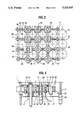
- FIG. 3 is a top view of the control rod drive housing supports of the present invention.
- FIG. 4 is side view of two embodiments of the control rod drive housing supports of the present invention and the control rod drives.
- FIG. 5A is a top view of a wing assembly of the control rod drive housing supports according to one of the embodiments of the present invention shown in FIG. 4.
- FIG. 5B is a top view of a support bar used with the wing assembly of FIG. 5A.
- FIG. 5C is a cross-sectional side view of the wing assembly and support bar of FIGS. 5A and 5B.
- FIG. 6A is a top view of a wing assembly of the control rod drive housing supports according to another of the embodiments of the present invention shown in FIG. 4.
- FIG. 6B is a top view of a support bar used with the wing assembly of FIG. 6A.
- FIG. 6C is a cross-sectional side view of the wing assembly and support bar of FIGS. 6A and 6B.
- FIG. 7 is side view of another embodiment of the control rod housing supports of the present invention.
- FIG. 8A is a top view of the removable wing assembly and the support bar of the control rod housing supports of the present invention according to the embodiment of FIG. 7.
- FIG. 8B is a side view of the support bar of the control rod drive housing supports of FIG. 8A.
- FIG. 8C is another view of the support bar and removable wing assembly of FIGS. 7, 7A and 8B.
- FIG. 9 is a side view of the support bar of the control rod drive housing supports of an embodiment of the present invention.
- FIG. 10 is a side view of the support bar of the control rod drive housing supports of another embodiment of the present invention.
- FIG. 11 is a side view of the support bar of the control rod drive housing supports of another embodiment of the present invention.
- Boiling water reactors use control rods in the reactor vessel for controlling the reaction therein.
- the control rods are generally contained in a grid-like fashion in a control rod housing with a drive unit for raising the control rods into the assembly of the fuel rods.
- control rod drive housing supports Located underneath the reactor vessel near the control rod housings are control rod drive housing supports for limiting the travel of a control rod in the event that a control rod housing is ruptured.
- FIGS. 1 and 2 A top view of the control rod drive housing supports of the prior art and the present invention are shown in FIGS. 1 and 2, respectively.
- the positions shown at 10 illustrate the positions which correspond to a control rod drive.
- the control rod drive housing supports of the prior art as shown in FIG. 1, consist of hanger rods 11 supported by a beam underneath the reactor pressure vessel (not shown) spaced throughout the grid of control rod drive positions.
- Support bars 12 are bolted between the hanger rods 11.
- Grid bars 13 are installed on the support bars 12 to support the control rod drive and transfer the load of the control rod drive to the support bars 12.
- a pair of grid bars 13 support each control rod drive.
- Each pair of grid bars is held together by two grid clamps 14 and a bolt (not shown).
- control drive housing supports of the prior art is shown to the right of line A--A only with the support bars 12 and is shown with the support bars 12 and grid bars 13 to the left of the line A--A.
- the grid bars 13 would be used throughout the entire housing supports.
- the grid bars 13 and clamps 14 In order to replace a control rod drive, the grid bars 13 and clamps 14 must be removed. Because the grid bars 13 are interlocking, they must be removed starting from the periphery, resulting in a cumbersome and time consuming process.
- control rod drive housing supports of the present invention will be described.
- the control rod drive positions and hanger rods are again shown at 10 and 11, respectively.
- the grid bars 13 and the clamps 14 of the prior art are replaced by assemblies that can perform the same function but can be moved to a nonuse position, rather than removed, when changing the control rod drives.
- no heavy steel grid bars must be removed every time a control rod drive is being replaced.
- changing of the control rod drives is much easier and faster.
- the time needed to replace a control rod drive is greatly reduced, the length of time a person changing the control rod drive is subject to radiation is correspondingly reduced.
- the support bars 12 of the prior art are replaced with support bars 22 placed in rows along opposing sides of the control rod drive position and oriented ninety degrees to the old bar support bars 12.
- An end of each support bar 22 is supported on a hanger rod.
- the support bars 12 of the prior art were one foot long.
- the length of support bars 22 of the present invention may vary depending on the reactor and the placement of the hangers. Preferably, the length of the support bars 22 is two feet.
- Each support bar has wing assemblies 25 having four wings 30 disposed thereon for supporting the control rod drives.
- the wing assembly 25 When the plant is in operation, the wing assembly 25 is oriented in an operating position 32 as shown in FIGS. 1 and 2.
- the wing assembly 25 and wings 30 may be turned to a non-support position 33 as shown in FIG. 2 rather than removed.
- the wing assemblies 25 are spaced on the support bar to correspond with the control rod drive positions 10. While the number of wing assemblies on each support bar may vary, generally the support bar is a straight piece of carbon steel having three wing assemblies 25 thereon. Further, the wing assemblies 25 are alternately placed on the hanger rods 11 on which the support bar 22 is attached.
- FIG. 4 The relationship of the support bar 22, the wing assembly 25 and the control rod drive is illustrated in FIG. 4.
- the lower end of a control rod drive is shown at 20.
- the control rod drive 20 consists of a flange 17 and a flange bolt 18.
- the wing assembly 25 is shown on the support bar 22 which in turn is provided on the hangers 11.
- the support bar 22 has a hub 27 thereon for receiving the wing assembly 25.
- the support bar 22 is provided on a hanger rod 11 at its one end through the wing assembly hub 28 and on another hanger rod 11 at its other end through a hanger rod hub 26.
- the wing assembly 25 is also shown on a hanger rod 11 at 29. At a hanger rod 11, the wing assembly 25 is inserted over a hub 28 on the support bar 22 which has been inserted over the hanger rod 11.
- FIG. 4 also illustrates another wing assembly 45 which will be described in more detail below.
- the wing assembly 25 is provided below the control rod drive flange bolt 18 with some clearance to allow for thermal expansion of the control rod drive when the plant is in operation. As a result, a gap 34 exists between the control rod drive flange 17 and flange bolt 18 and the wing assemblies 25. The gap 34 must be sufficient to allow the control rod drive 20 to expand as the system heats up during operation, preferably three quarters of an inch.
- the control rod drive 20 expands and the gap 34 between the flange 17 and the bolt 18 and the wings 30 is reduced so that the flange bolt 18 and wing are almost touching.
- the gap is reduced to about one quarter of an inch.
- Notches can be provided between the wing assembly 25 and the support bar hub 27 to provide an locking means for the wing assemblies 25.
- the wing assembly 25 cannot move when the plant is in operation and is thereby locked into the operating position 32.
- the control rod drives must be replaced or serviced, the operation of the plant is stopped and the plant cools down.
- the control rod drives reduce in size and the gap between the flange 17 and flange bolt 18 and the wing assembly 25 increases to its original clearance. At such clearance the wing assembly 25 may be turned to the non-operating position 33 whereby the wing assembly 25 does not interfere with the service and removal of a control rod drive 20.
- the wing assemblies 25 moves freely.
- FIG. 5A is a top view of the wing assembly 25 including wings 30.
- FIG. 5B a top view of the support bar 22 and the hubs 26, 27 and 28 are shown.
- the hub 27 supports the wing assembly 25 between hanger rod positions 11.
- a side view of the support bar 22 with hubs 26, 27 and 28 and wing assemblies 25 is shown in FIG. 5C.
- the wing assemblies 25, for purposes of illustrating the relationship of the wing assembly 25 to the support bar 22, are shown above the support bar 22.
- the hubs 26 and 28 have a hole therethrough sized to fit around the hanger rods 11.
- the wing assembly 25 has a hole 29 therethrough sized to fit over the hubs 27 and 28.
- the hanger rods 11 support the support bars 22 which in turn supports the wing assemblies 25.
- the present invention includes two alternative wing assemblies to cover various situations around the control rod drive.
- core detectors may be placed throughout the grid of control rod drives. Specifically Start-up Range Monitor/Intermediate Range Monitors (“SRM/IRM”) core detector and Local Power Range Monitors (“LPRM”) core detector may be provided throughout the grid of control rod drives to monitor the reactor core.
- SRM/IRM Start-up Range Monitor/Intermediate Range Monitors
- LPRM Local Power Range Monitors
- the alternative wing assemblies will be described in connection with a SRM/IRM detector and LPRM detector, the invention may be used with other instruments.
- the SRM/IRM and LPRM detectors are placed at the positions shown at 40 and 50, respectively in FIGS. 1, 2 and 3. Due to the nature of these detectors, alternate wing assemblies may be used in conjunction with these detectors.
- FIG. 4 An LPRM detector 40 having a flange 41 is shown in FIG. 4, with a LPRM position wing assembly 45 on a LPRM position support bar 42.
- the LPRM position wing assembly 45 as shown, is installed around the LPRM detector 40.
- the LPRM position wing assembly 45 and support bar 42 are also illustrated in FIGS. 6A, 6B and 6C.
- FIG. 6A is a top view of the LPRM position wing assembly 45 having wings 44.
- FIG. 6B is a top view of the support bar 42 having hubs 46 and 48 and a throughhole 47.
- FIG. 6C is a side view of the wing assemblies 25 and 45 and the support bar 42.
- the support bar 42 has a hub 48 for placement over a hanger rod 11 and for receiving a wing assembly 25 and a hub 46 for placement over a hanger rod 11.
- Support bar 42 is provided with a throughhole 47 rather than a hub.
- the hole 47 is sized to receive an extension 43 of the LPRM position wing assembly 45.
- a hole 49 is provided through the wing assembly 45 which is sized to receive the LPRM detector 40 or another instrument therethrough.
- the LPRM detector 40 In use, the LPRM detector 40 extends through the wing assembly 45 and the support bar 42.
- the wing assembly 45 rotates on the LPRM detector 40 from a non-support position to a support position and vice versa.
- Notches may also be provided between the support bar 42 and wing assembly 45 and extension 43 to further retain the wing assembly 45 in a support position during operation of the plant.
- the control rod drives can be serviced or replaced without removing the LPRM detectors.
- An SRM/IRM detector 50 having a flange 51 is shown in FIG. 7 with an SRM/IRM position wing assembly 55 on an SRM/IRM position support bar 52.
- the SRM/IRM detector has a drive unit 62 and a gear box 63 associated therewith. Because of the shape of the SRM/IRM detector 50 and gear box 63, the detector 50 may interfere with the operation of the previously described wing assembly 25 such that rotation of that assembly may not be possible. As a result, depending on the size of the SRM/IRM unit, it may not be possible to use the wing assembly 25 or 45 because it may not be possible to move the wing assembly to a position which does not interfere with the control rods 20. With such an event a wing assembly 55 having two removable wing blocks 54 may be employed. As shown in FIG. 7, the wing assembly 55 is located between the flange 51 and the gear box 63.
- FIG. 8A is a top view of a wing assembly 55 and the support bar 52.
- the wing assembly 55 has two wing blocks 54 which are bolted to the support bar 52 at 59 when in operation but which can be removed for service of the control rods.
- the wing blocks are shown removed from the hub in FIG. 8A.
- FIG. 8B illustrates a side view of the support bar 52.
- the support bar 52 has a hub 58 and 56 for placement over hanger rods 11. As shown in FIGS. 7 and 8B, the hub 58 may be used in a high support position and hub 56 may be used in a low support position.
- the support bar 52 also has a hole 57 sized to receive the SRM/IRM detector or another instrument therethrough.
- FIG. 8C illustrates another view of the support bar 52 and the removable wing block 44.
- the wing blocks 47 are removable to allow for replacement or service of the SRM/IRM detector or the surrounding control rod drives.
- FIGS. 9, 10 and 11 Alternative support bars for each of the situations described in the above embodiments of the present invention are shown in FIGS. 9, 10 and 11.
- every other support bar has either an upper or a lower hub.
- the total number of support bars used is increased.
- the removal and installation of a specific support is simplified because a maximum of three support bars need be removed in order to access any position.
- only one support bar need be removed. This is to be compared with the main embodiment described above where all the support bars have to be removed from the periphery until the specific bar to be accessed is reached.
- FIG. 9 illustrates a row of support bars 22 without any detector positions.
- the support bars 22 alternately have upper hubs 61 and lower hubs 62.
- FIG. 10 illustrates a row of support bars with LPRM detector positions.
- the support bars 42 are also shown having alternately, upper hubs 61 and lower hubs 62.
- FIG. 11 illustrates a row of support bars with SRM/IRM detector positions. Both the SRM/IRM support bars 52 and the support bar 22 are shown.
- the support bars 52 are also shown with upper hubs 61 and lower hubs 62.
Abstract
Description
Claims (20)
Priority Applications (4)
| Application Number | Priority Date | Filing Date | Title |
|---|---|---|---|
| US08/092,064 US5323435A (en) | 1993-07-16 | 1993-07-16 | Control rod housing support bars with wing assemblies |
| TW083100681A TW229316B (en) | 1993-07-16 | 1994-01-27 | Control rod housing support bars with wing assemblies |
| ES09401481A ES2106657B1 (en) | 1993-07-16 | 1994-07-07 | SUPPORT BARS FOR CONTROL RODS FRAME WITH WING ASSEMBLIES. |
| JP6183068A JPH0755982A (en) | 1993-07-16 | 1994-07-13 | Supporting body for housing of control-rod driving device of boiling water reactor |
Applications Claiming Priority (1)
| Application Number | Priority Date | Filing Date | Title |
|---|---|---|---|
| US08/092,064 US5323435A (en) | 1993-07-16 | 1993-07-16 | Control rod housing support bars with wing assemblies |
Publications (1)
| Publication Number | Publication Date |
|---|---|
| US5323435A true US5323435A (en) | 1994-06-21 |
Family
ID=22231285
Family Applications (1)
| Application Number | Title | Priority Date | Filing Date |
|---|---|---|---|
| US08/092,064 Expired - Lifetime US5323435A (en) | 1993-07-16 | 1993-07-16 | Control rod housing support bars with wing assemblies |
Country Status (4)
| Country | Link |
|---|---|
| US (1) | US5323435A (en) |
| JP (1) | JPH0755982A (en) |
| ES (1) | ES2106657B1 (en) |
| TW (1) | TW229316B (en) |
Cited By (12)
| Publication number | Priority date | Publication date | Assignee | Title |
|---|---|---|---|---|
| US5570402A (en) * | 1994-08-04 | 1996-10-29 | Combustion Engineering, Inc. | Control rod housing support system with radiation shield rings |
| US7955285B2 (en) | 1998-06-01 | 2011-06-07 | Bonutti Research Inc. | Shoulder orthosis |
| US7981067B2 (en) | 2004-03-08 | 2011-07-19 | Bonutti Research Inc. | Range of motion device |
| US8012108B2 (en) | 2005-08-12 | 2011-09-06 | Bonutti Research, Inc. | Range of motion system and method |
| US8038637B2 (en) | 2000-09-18 | 2011-10-18 | Bonutti Research, Inc. | Finger orthosis |
| US8062241B2 (en) | 2000-12-15 | 2011-11-22 | Bonutti Research Inc | Myofascial strap |
| US8066656B2 (en) | 2005-10-28 | 2011-11-29 | Bonutti Research, Inc. | Range of motion device |
| US8251934B2 (en) | 2000-12-01 | 2012-08-28 | Bonutti Research, Inc. | Orthosis and method for cervical mobilization |
| US8273043B2 (en) | 2007-07-25 | 2012-09-25 | Bonutti Research, Inc. | Orthosis apparatus and method of using an orthosis apparatus |
| US8905950B2 (en) | 2008-03-04 | 2014-12-09 | Bonutti Research, Inc. | Shoulder ROM orthosis |
| US8920346B2 (en) | 2007-02-05 | 2014-12-30 | Bonutti Research Inc. | Knee orthosis |
| US9402759B2 (en) | 2013-02-05 | 2016-08-02 | Bonutti Research, Inc. | Cervical traction systems and method |
Citations (4)
| Publication number | Priority date | Publication date | Assignee | Title |
|---|---|---|---|---|
| US4752434A (en) * | 1985-01-28 | 1988-06-21 | Framatome | Control bar and drive mechanism coupling device |
| US4820058A (en) * | 1984-07-26 | 1989-04-11 | Westinghouse Electric Corp. | Control rod end plug with a stabilizing configuration |
| US4859409A (en) * | 1988-05-27 | 1989-08-22 | Westinghouse Electric Corp. | Reactor vessel lower internals temporary support |
| US4888149A (en) * | 1988-09-27 | 1989-12-19 | Combustion Engineering, Inc. | Wear-reduction-shield for thimbles |
Family Cites Families (3)
| Publication number | Priority date | Publication date | Assignee | Title |
|---|---|---|---|---|
| FR2575581B1 (en) * | 1984-12-27 | 1987-03-06 | Framatome & Cie | DEVICE FOR MOVING AND HANGING A CLUSTER OF NUCLEAR REACTOR CONTROL PENCILS |
| FR2575582B1 (en) * | 1984-12-28 | 1987-03-06 | Framatome Sa | DEVICE AND METHOD FOR HANGING A STEERING ROD FOR A CONTROL CLUSTER IN A NUCLEAR REACTOR |
| DE4103496A1 (en) * | 1991-02-06 | 1992-08-20 | Bbc Reaktor Gmbh | METHOD AND ARRANGEMENT FOR REPAIRING CONTROL ELEMENTS OF A PRESSURE WATER REACTOR |
-
1993
- 1993-07-16 US US08/092,064 patent/US5323435A/en not_active Expired - Lifetime
-
1994
- 1994-01-27 TW TW083100681A patent/TW229316B/en active
- 1994-07-07 ES ES09401481A patent/ES2106657B1/en not_active Expired - Lifetime
- 1994-07-13 JP JP6183068A patent/JPH0755982A/en active Pending
Patent Citations (4)
| Publication number | Priority date | Publication date | Assignee | Title |
|---|---|---|---|---|
| US4820058A (en) * | 1984-07-26 | 1989-04-11 | Westinghouse Electric Corp. | Control rod end plug with a stabilizing configuration |
| US4752434A (en) * | 1985-01-28 | 1988-06-21 | Framatome | Control bar and drive mechanism coupling device |
| US4859409A (en) * | 1988-05-27 | 1989-08-22 | Westinghouse Electric Corp. | Reactor vessel lower internals temporary support |
| US4888149A (en) * | 1988-09-27 | 1989-12-19 | Combustion Engineering, Inc. | Wear-reduction-shield for thimbles |
Cited By (20)
| Publication number | Priority date | Publication date | Assignee | Title |
|---|---|---|---|---|
| US5570402A (en) * | 1994-08-04 | 1996-10-29 | Combustion Engineering, Inc. | Control rod housing support system with radiation shield rings |
| US7955285B2 (en) | 1998-06-01 | 2011-06-07 | Bonutti Research Inc. | Shoulder orthosis |
| US8038637B2 (en) | 2000-09-18 | 2011-10-18 | Bonutti Research, Inc. | Finger orthosis |
| US8251934B2 (en) | 2000-12-01 | 2012-08-28 | Bonutti Research, Inc. | Orthosis and method for cervical mobilization |
| US9681977B2 (en) | 2000-12-01 | 2017-06-20 | Bonutti Research, Inc. | Apparatus and method for spinal distraction |
| US8062241B2 (en) | 2000-12-15 | 2011-11-22 | Bonutti Research Inc | Myofascial strap |
| US9445966B2 (en) | 2004-03-08 | 2016-09-20 | Bonutti Research, Inc. | Range of motion device |
| US9314392B2 (en) | 2004-03-08 | 2016-04-19 | Bonutti Research, Inc. | Range of motion device |
| US7981067B2 (en) | 2004-03-08 | 2011-07-19 | Bonutti Research Inc. | Range of motion device |
| US8784343B2 (en) | 2005-08-12 | 2014-07-22 | Bonutti Research, Inc. | Range of motion system |
| US8012108B2 (en) | 2005-08-12 | 2011-09-06 | Bonutti Research, Inc. | Range of motion system and method |
| US9320669B2 (en) | 2005-08-12 | 2016-04-26 | Bonutti Research, Inc. | Range of motion system |
| US9468578B2 (en) | 2005-10-28 | 2016-10-18 | Bonutti Research Inc. | Range of motion device |
| US8066656B2 (en) | 2005-10-28 | 2011-11-29 | Bonutti Research, Inc. | Range of motion device |
| US10456314B2 (en) | 2005-10-28 | 2019-10-29 | Bonutti Research, Inc. | Range of motion device |
| US8920346B2 (en) | 2007-02-05 | 2014-12-30 | Bonutti Research Inc. | Knee orthosis |
| US9980871B2 (en) | 2007-02-05 | 2018-05-29 | Bonutti Research, Inc. | Knee orthosis |
| US8273043B2 (en) | 2007-07-25 | 2012-09-25 | Bonutti Research, Inc. | Orthosis apparatus and method of using an orthosis apparatus |
| US8905950B2 (en) | 2008-03-04 | 2014-12-09 | Bonutti Research, Inc. | Shoulder ROM orthosis |
| US9402759B2 (en) | 2013-02-05 | 2016-08-02 | Bonutti Research, Inc. | Cervical traction systems and method |
Also Published As
| Publication number | Publication date |
|---|---|
| ES2106657A1 (en) | 1997-11-01 |
| JPH0755982A (en) | 1995-03-03 |
| TW229316B (en) | 1994-09-01 |
| ES2106657B1 (en) | 1998-06-01 |
Similar Documents
| Publication | Publication Date | Title |
|---|---|---|
| US5323435A (en) | Control rod housing support bars with wing assemblies | |
| EP0634753B1 (en) | Locking assembly for nuclear fuel bundles | |
| US3802996A (en) | Fuel assemblies,grapples therefor and fuel transport apparatus for nu | |
| US4323428A (en) | Reconstitutable fuel assembly for a nuclear reactor | |
| US7139359B2 (en) | Integrated head assembly for a nuclear reactor | |
| US6618460B2 (en) | Integrated head assembly for a nuclear reactor | |
| US4687619A (en) | Removable top nozzle and tool for a nuclear reactor fuel assembly | |
| EP0184345B1 (en) | Modular radial neutron reflector | |
| US4666657A (en) | Remotely adjustable intermediate seismic support | |
| US5481117A (en) | Shipping container for a nuclear fuel assembly | |
| US4828789A (en) | Reactor vessel head permanent shield | |
| JPS5940280B2 (en) | fuel assembly | |
| JPS59137887A (en) | Nuclear fuel assembly | |
| US5098647A (en) | Guide tube insert assembly for use in a nuclear reactor | |
| US4876061A (en) | Resiliently loaded lateral supports for cantilever-mounted rod guides of a pressurized water reactor | |
| US3910816A (en) | Method and apparatus for removing an incore neutron flux monitor | |
| US5363423A (en) | Quick release top nozzle assembly | |
| US5321732A (en) | Control rod housing support bars with radiation shields | |
| RU2077965C1 (en) | Rolling mill | |
| US5282232A (en) | Nuclear reactor upper internal equipment with cluster guide devices | |
| US5133926A (en) | Extended burnup top nozzle for a nuclear fuel assembly | |
| US4859409A (en) | Reactor vessel lower internals temporary support | |
| US3917335A (en) | Fuel assemblies, grapples therefor and fuel transport apparatus for nuclear reactor power plant | |
| EP0266592A2 (en) | Simplified, flexible top end support for cantilever-mounted rod guides of a pressurized water reactor | |
| US5570402A (en) | Control rod housing support system with radiation shield rings |
Legal Events
| Date | Code | Title | Description |
|---|---|---|---|
| STPP | Information on status: patent application and granting procedure in general |
Free format text: APPLICATION UNDERGOING PREEXAM PROCESSING |
|
| AS | Assignment |
Owner name: COMBUSTION ENGINEERING INC., CONNECTICUT Free format text: ASSIGNMENT OF ASSIGNORS INTEREST;ASSIGNOR:BAVERSTEN, BENGT I.;REEL/FRAME:006708/0261 Effective date: 19930830 |
|
| FEPP | Fee payment procedure |
Free format text: PAYOR NUMBER ASSIGNED (ORIGINAL EVENT CODE: ASPN); ENTITY STATUS OF PATENT OWNER: LARGE ENTITY |
|
| FPAY | Fee payment |
Year of fee payment: 4 |
|
| AS | Assignment |
Owner name: ABB COMBUSTION ENGINEERING NUCLEAR POWER, INC., CO Free format text: ASSIGNMENT OF ASSIGNORS INTEREST;ASSIGNOR:COMBUSTION ENGINEERING, INC.;REEL/FRAME:010070/0603 Effective date: 19990630 |
|
| AS | Assignment |
Owner name: CE NUCLEAR POWER LLC, CONNECTICUT Free format text: MERGER AND CHANGE OF NAME;ASSIGNOR:ABB C-E NUCLEAR POWER, INC.;REEL/FRAME:011035/0466 Effective date: 20000428 Owner name: ABB C-E NUCLEAR POWER, INC., CONNECTICUT Free format text: MERGER/CHANGE OF NAME;ASSIGNOR:ABB COMBUSTION ENGINEERING NUCLEAR POWER, INC.;REEL/FRAME:011035/0483 Effective date: 19991216 |
|
| AS | Assignment |
Owner name: WESTINGHOUSE ELECTRIC CO. LLC, PENNSYLVANIA Free format text: MERGER;ASSIGNOR:CE NUCLEAR POWER LLC;REEL/FRAME:011742/0299 Effective date: 20010402 |
|
| FPAY | Fee payment |
Year of fee payment: 8 |
|
| FPAY | Fee payment |
Year of fee payment: 12 |