US5334169A - Reinforced catheter with thin monolithic walls - Google Patents
Reinforced catheter with thin monolithic walls Download PDFInfo
- Publication number
- US5334169A US5334169A US07/881,422 US88142292A US5334169A US 5334169 A US5334169 A US 5334169A US 88142292 A US88142292 A US 88142292A US 5334169 A US5334169 A US 5334169A
- Authority
- US
- United States
- Prior art keywords
- catheter
- walls
- monolithic
- reinforcement
- strands
- Prior art date
- Legal status (The legal status is an assumption and is not a legal conclusion. Google has not performed a legal analysis and makes no representation as to the accuracy of the status listed.)
- Expired - Fee Related
Links
- 230000002787 reinforcement Effects 0.000 claims abstract description 66
- 239000000463 material Substances 0.000 claims abstract description 62
- 239000007787 solid Substances 0.000 claims abstract description 18
- 239000000314 lubricant Substances 0.000 claims abstract description 16
- 230000010412 perfusion Effects 0.000 claims abstract description 8
- 239000011737 fluorine Substances 0.000 claims abstract description 4
- 229910052731 fluorine Inorganic materials 0.000 claims abstract description 4
- 230000009467 reduction Effects 0.000 claims description 19
- 230000002093 peripheral effect Effects 0.000 claims description 14
- 230000003247 decreasing effect Effects 0.000 claims description 2
- 239000012858 resilient material Substances 0.000 claims 3
- 125000001153 fluoro group Chemical group F* 0.000 claims 1
- 239000002210 silicon-based material Substances 0.000 claims 1
- 238000001125 extrusion Methods 0.000 abstract description 30
- 238000003466 welding Methods 0.000 abstract description 20
- 238000004519 manufacturing process Methods 0.000 abstract description 18
- 238000000034 method Methods 0.000 abstract description 16
- 238000012986 modification Methods 0.000 abstract description 4
- 230000004048 modification Effects 0.000 abstract description 4
- YCKRFDGAMUMZLT-UHFFFAOYSA-N Fluorine atom Chemical compound [F] YCKRFDGAMUMZLT-UHFFFAOYSA-N 0.000 abstract description 3
- 239000002245 particle Substances 0.000 abstract description 3
- 238000003801 milling Methods 0.000 abstract description 2
- 150000003377 silicon compounds Chemical class 0.000 abstract description 2
- 208000027418 Wounds and injury Diseases 0.000 description 8
- 239000002826 coolant Substances 0.000 description 7
- 230000005540 biological transmission Effects 0.000 description 6
- 238000010276 construction Methods 0.000 description 6
- 238000005520 cutting process Methods 0.000 description 6
- 239000012530 fluid Substances 0.000 description 5
- 230000008569 process Effects 0.000 description 5
- 238000001816 cooling Methods 0.000 description 3
- 239000000835 fiber Substances 0.000 description 3
- 238000005461 lubrication Methods 0.000 description 3
- 238000002844 melting Methods 0.000 description 3
- 230000008018 melting Effects 0.000 description 3
- 230000002792 vascular Effects 0.000 description 3
- 238000004804 winding Methods 0.000 description 3
- IJGRMHOSHXDMSA-UHFFFAOYSA-N Atomic nitrogen Chemical compound N#N IJGRMHOSHXDMSA-UHFFFAOYSA-N 0.000 description 2
- XEEYBQQBJWHFJM-UHFFFAOYSA-N Iron Chemical compound [Fe] XEEYBQQBJWHFJM-UHFFFAOYSA-N 0.000 description 2
- 230000006378 damage Effects 0.000 description 2
- 230000000694 effects Effects 0.000 description 2
- 238000005516 engineering process Methods 0.000 description 2
- 230000006870 function Effects 0.000 description 2
- 238000010438 heat treatment Methods 0.000 description 2
- 208000014674 injury Diseases 0.000 description 2
- 239000007788 liquid Substances 0.000 description 2
- 239000002184 metal Substances 0.000 description 2
- 229910052751 metal Inorganic materials 0.000 description 2
- 238000013021 overheating Methods 0.000 description 2
- 238000000926 separation method Methods 0.000 description 2
- RYGMFSIKBFXOCR-UHFFFAOYSA-N Copper Chemical compound [Cu] RYGMFSIKBFXOCR-UHFFFAOYSA-N 0.000 description 1
- XUIMIQQOPSSXEZ-UHFFFAOYSA-N Silicon Chemical compound [Si] XUIMIQQOPSSXEZ-UHFFFAOYSA-N 0.000 description 1
- 230000006978 adaptation Effects 0.000 description 1
- 230000004075 alteration Effects 0.000 description 1
- 238000001574 biopsy Methods 0.000 description 1
- 230000015572 biosynthetic process Effects 0.000 description 1
- 239000010839 body fluid Substances 0.000 description 1
- 210000001124 body fluid Anatomy 0.000 description 1
- 238000009954 braiding Methods 0.000 description 1
- 239000012809 cooling fluid Substances 0.000 description 1
- 238000013461 design Methods 0.000 description 1
- 238000005553 drilling Methods 0.000 description 1
- 239000003814 drug Substances 0.000 description 1
- 239000011152 fibreglass Substances 0.000 description 1
- 230000004927 fusion Effects 0.000 description 1
- 239000011521 glass Substances 0.000 description 1
- 239000003365 glass fiber Substances 0.000 description 1
- 230000017525 heat dissipation Effects 0.000 description 1
- 230000000266 injurious effect Effects 0.000 description 1
- 238000003780 insertion Methods 0.000 description 1
- 230000037431 insertion Effects 0.000 description 1
- 229910052742 iron Inorganic materials 0.000 description 1
- 239000011159 matrix material Substances 0.000 description 1
- 239000000203 mixture Substances 0.000 description 1
- 239000012768 molten material Substances 0.000 description 1
- 229910052757 nitrogen Inorganic materials 0.000 description 1
- 239000004033 plastic Substances 0.000 description 1
- 229920000642 polymer Polymers 0.000 description 1
- 239000000843 powder Substances 0.000 description 1
- 238000004080 punching Methods 0.000 description 1
- 229910052710 silicon Inorganic materials 0.000 description 1
- 239000010703 silicon Substances 0.000 description 1
- 239000002002 slurry Substances 0.000 description 1
- 229910001220 stainless steel Inorganic materials 0.000 description 1
- 239000010935 stainless steel Substances 0.000 description 1
- 238000006467 substitution reaction Methods 0.000 description 1
- 229920002994 synthetic fiber Polymers 0.000 description 1
- 229920001169 thermoplastic Polymers 0.000 description 1
- 239000004416 thermosoftening plastic Substances 0.000 description 1
- 230000003313 weakening effect Effects 0.000 description 1
Images


Classifications
-
- A—HUMAN NECESSITIES
- A61—MEDICAL OR VETERINARY SCIENCE; HYGIENE
- A61M—DEVICES FOR INTRODUCING MEDIA INTO, OR ONTO, THE BODY; DEVICES FOR TRANSDUCING BODY MEDIA OR FOR TAKING MEDIA FROM THE BODY; DEVICES FOR PRODUCING OR ENDING SLEEP OR STUPOR
- A61M25/00—Catheters; Hollow probes
- A61M25/0009—Making of catheters or other medical or surgical tubes
- A61M25/0012—Making of catheters or other medical or surgical tubes with embedded structures, e.g. coils, braids, meshes, strands or radiopaque coils
-
- A—HUMAN NECESSITIES
- A61—MEDICAL OR VETERINARY SCIENCE; HYGIENE
- A61M—DEVICES FOR INTRODUCING MEDIA INTO, OR ONTO, THE BODY; DEVICES FOR TRANSDUCING BODY MEDIA OR FOR TAKING MEDIA FROM THE BODY; DEVICES FOR PRODUCING OR ENDING SLEEP OR STUPOR
- A61M25/00—Catheters; Hollow probes
- A61M25/0021—Catheters; Hollow probes characterised by the form of the tubing
- A61M25/0023—Catheters; Hollow probes characterised by the form of the tubing by the form of the lumen, e.g. cross-section, variable diameter
-
- A—HUMAN NECESSITIES
- A61—MEDICAL OR VETERINARY SCIENCE; HYGIENE
- A61M—DEVICES FOR INTRODUCING MEDIA INTO, OR ONTO, THE BODY; DEVICES FOR TRANSDUCING BODY MEDIA OR FOR TAKING MEDIA FROM THE BODY; DEVICES FOR PRODUCING OR ENDING SLEEP OR STUPOR
- A61M25/00—Catheters; Hollow probes
- A61M25/0043—Catheters; Hollow probes characterised by structural features
- A61M25/005—Catheters; Hollow probes characterised by structural features with embedded materials for reinforcement, e.g. wires, coils, braids
-
- B—PERFORMING OPERATIONS; TRANSPORTING
- B29—WORKING OF PLASTICS; WORKING OF SUBSTANCES IN A PLASTIC STATE IN GENERAL
- B29C—SHAPING OR JOINING OF PLASTICS; SHAPING OF MATERIAL IN A PLASTIC STATE, NOT OTHERWISE PROVIDED FOR; AFTER-TREATMENT OF THE SHAPED PRODUCTS, e.g. REPAIRING
- B29C48/00—Extrusion moulding, i.e. expressing the moulding material through a die or nozzle which imparts the desired form; Apparatus therefor
- B29C48/03—Extrusion moulding, i.e. expressing the moulding material through a die or nozzle which imparts the desired form; Apparatus therefor characterised by the shape of the extruded material at extrusion
- B29C48/06—Rod-shaped
-
- B—PERFORMING OPERATIONS; TRANSPORTING
- B29—WORKING OF PLASTICS; WORKING OF SUBSTANCES IN A PLASTIC STATE IN GENERAL
- B29C—SHAPING OR JOINING OF PLASTICS; SHAPING OF MATERIAL IN A PLASTIC STATE, NOT OTHERWISE PROVIDED FOR; AFTER-TREATMENT OF THE SHAPED PRODUCTS, e.g. REPAIRING
- B29C48/00—Extrusion moulding, i.e. expressing the moulding material through a die or nozzle which imparts the desired form; Apparatus therefor
- B29C48/03—Extrusion moulding, i.e. expressing the moulding material through a die or nozzle which imparts the desired form; Apparatus therefor characterised by the shape of the extruded material at extrusion
- B29C48/09—Articles with cross-sections having partially or fully enclosed cavities, e.g. pipes or channels
-
- B—PERFORMING OPERATIONS; TRANSPORTING
- B29—WORKING OF PLASTICS; WORKING OF SUBSTANCES IN A PLASTIC STATE IN GENERAL
- B29C—SHAPING OR JOINING OF PLASTICS; SHAPING OF MATERIAL IN A PLASTIC STATE, NOT OTHERWISE PROVIDED FOR; AFTER-TREATMENT OF THE SHAPED PRODUCTS, e.g. REPAIRING
- B29C48/00—Extrusion moulding, i.e. expressing the moulding material through a die or nozzle which imparts the desired form; Apparatus therefor
- B29C48/03—Extrusion moulding, i.e. expressing the moulding material through a die or nozzle which imparts the desired form; Apparatus therefor characterised by the shape of the extruded material at extrusion
- B29C48/12—Articles with an irregular circumference when viewed in cross-section, e.g. window profiles
-
- B—PERFORMING OPERATIONS; TRANSPORTING
- B29—WORKING OF PLASTICS; WORKING OF SUBSTANCES IN A PLASTIC STATE IN GENERAL
- B29C—SHAPING OR JOINING OF PLASTICS; SHAPING OF MATERIAL IN A PLASTIC STATE, NOT OTHERWISE PROVIDED FOR; AFTER-TREATMENT OF THE SHAPED PRODUCTS, e.g. REPAIRING
- B29C48/00—Extrusion moulding, i.e. expressing the moulding material through a die or nozzle which imparts the desired form; Apparatus therefor
- B29C48/03—Extrusion moulding, i.e. expressing the moulding material through a die or nozzle which imparts the desired form; Apparatus therefor characterised by the shape of the extruded material at extrusion
- B29C48/13—Articles with a cross-section varying in the longitudinal direction, e.g. corrugated pipes
-
- B—PERFORMING OPERATIONS; TRANSPORTING
- B29—WORKING OF PLASTICS; WORKING OF SUBSTANCES IN A PLASTIC STATE IN GENERAL
- B29C—SHAPING OR JOINING OF PLASTICS; SHAPING OF MATERIAL IN A PLASTIC STATE, NOT OTHERWISE PROVIDED FOR; AFTER-TREATMENT OF THE SHAPED PRODUCTS, e.g. REPAIRING
- B29C48/00—Extrusion moulding, i.e. expressing the moulding material through a die or nozzle which imparts the desired form; Apparatus therefor
- B29C48/15—Extrusion moulding, i.e. expressing the moulding material through a die or nozzle which imparts the desired form; Apparatus therefor incorporating preformed parts or layers, e.g. extrusion moulding around inserts
- B29C48/151—Coating hollow articles
- B29C48/152—Coating hollow articles the inner surfaces thereof
- B29C48/153—Coating both inner and outer surfaces
-
- B—PERFORMING OPERATIONS; TRANSPORTING
- B29—WORKING OF PLASTICS; WORKING OF SUBSTANCES IN A PLASTIC STATE IN GENERAL
- B29C—SHAPING OR JOINING OF PLASTICS; SHAPING OF MATERIAL IN A PLASTIC STATE, NOT OTHERWISE PROVIDED FOR; AFTER-TREATMENT OF THE SHAPED PRODUCTS, e.g. REPAIRING
- B29C48/00—Extrusion moulding, i.e. expressing the moulding material through a die or nozzle which imparts the desired form; Apparatus therefor
- B29C48/15—Extrusion moulding, i.e. expressing the moulding material through a die or nozzle which imparts the desired form; Apparatus therefor incorporating preformed parts or layers, e.g. extrusion moulding around inserts
- B29C48/156—Coating two or more articles simultaneously
-
- A—HUMAN NECESSITIES
- A61—MEDICAL OR VETERINARY SCIENCE; HYGIENE
- A61M—DEVICES FOR INTRODUCING MEDIA INTO, OR ONTO, THE BODY; DEVICES FOR TRANSDUCING BODY MEDIA OR FOR TAKING MEDIA FROM THE BODY; DEVICES FOR PRODUCING OR ENDING SLEEP OR STUPOR
- A61M25/00—Catheters; Hollow probes
- A61M25/0043—Catheters; Hollow probes characterised by structural features
- A61M2025/0062—Catheters; Hollow probes characterised by structural features having features to improve the sliding of one part within another by using lubricants or surfaces with low friction
-
- A—HUMAN NECESSITIES
- A61—MEDICAL OR VETERINARY SCIENCE; HYGIENE
- A61M—DEVICES FOR INTRODUCING MEDIA INTO, OR ONTO, THE BODY; DEVICES FOR TRANSDUCING BODY MEDIA OR FOR TAKING MEDIA FROM THE BODY; DEVICES FOR PRODUCING OR ENDING SLEEP OR STUPOR
- A61M25/00—Catheters; Hollow probes
- A61M25/0009—Making of catheters or other medical or surgical tubes
- A61M25/001—Forming the tip of a catheter, e.g. bevelling process, join or taper
-
- A—HUMAN NECESSITIES
- A61—MEDICAL OR VETERINARY SCIENCE; HYGIENE
- A61M—DEVICES FOR INTRODUCING MEDIA INTO, OR ONTO, THE BODY; DEVICES FOR TRANSDUCING BODY MEDIA OR FOR TAKING MEDIA FROM THE BODY; DEVICES FOR PRODUCING OR ENDING SLEEP OR STUPOR
- A61M25/00—Catheters; Hollow probes
- A61M25/0043—Catheters; Hollow probes characterised by structural features
- A61M25/005—Catheters; Hollow probes characterised by structural features with embedded materials for reinforcement, e.g. wires, coils, braids
- A61M25/0053—Catheters; Hollow probes characterised by structural features with embedded materials for reinforcement, e.g. wires, coils, braids having a variable stiffness along the longitudinal axis, e.g. by varying the pitch of the coil or braid
-
- B—PERFORMING OPERATIONS; TRANSPORTING
- B29—WORKING OF PLASTICS; WORKING OF SUBSTANCES IN A PLASTIC STATE IN GENERAL
- B29C—SHAPING OR JOINING OF PLASTICS; SHAPING OF MATERIAL IN A PLASTIC STATE, NOT OTHERWISE PROVIDED FOR; AFTER-TREATMENT OF THE SHAPED PRODUCTS, e.g. REPAIRING
- B29C48/00—Extrusion moulding, i.e. expressing the moulding material through a die or nozzle which imparts the desired form; Apparatus therefor
- B29C48/03—Extrusion moulding, i.e. expressing the moulding material through a die or nozzle which imparts the desired form; Apparatus therefor characterised by the shape of the extruded material at extrusion
- B29C48/09—Articles with cross-sections having partially or fully enclosed cavities, e.g. pipes or channels
- B29C48/10—Articles with cross-sections having partially or fully enclosed cavities, e.g. pipes or channels flexible, e.g. blown foils
-
- B—PERFORMING OPERATIONS; TRANSPORTING
- B29—WORKING OF PLASTICS; WORKING OF SUBSTANCES IN A PLASTIC STATE IN GENERAL
- B29K—INDEXING SCHEME ASSOCIATED WITH SUBCLASSES B29B, B29C OR B29D, RELATING TO MOULDING MATERIALS OR TO MATERIALS FOR MOULDS, REINFORCEMENTS, FILLERS OR PREFORMED PARTS, e.g. INSERTS
- B29K2105/00—Condition, form or state of moulded material or of the material to be shaped
- B29K2105/06—Condition, form or state of moulded material or of the material to be shaped containing reinforcements, fillers or inserts
- B29K2105/08—Condition, form or state of moulded material or of the material to be shaped containing reinforcements, fillers or inserts of continuous length, e.g. cords, rovings, mats, fabrics, strands or yarns
- B29K2105/10—Cords, strands or rovings, e.g. oriented cords, strands or rovings
- B29K2105/101—Oriented
-
- B—PERFORMING OPERATIONS; TRANSPORTING
- B29—WORKING OF PLASTICS; WORKING OF SUBSTANCES IN A PLASTIC STATE IN GENERAL
- B29L—INDEXING SCHEME ASSOCIATED WITH SUBCLASS B29C, RELATING TO PARTICULAR ARTICLES
- B29L2023/00—Tubular articles
- B29L2023/18—Pleated or corrugated hoses
-
- B—PERFORMING OPERATIONS; TRANSPORTING
- B29—WORKING OF PLASTICS; WORKING OF SUBSTANCES IN A PLASTIC STATE IN GENERAL
- B29L—INDEXING SCHEME ASSOCIATED WITH SUBCLASS B29C, RELATING TO PARTICULAR ARTICLES
- B29L2024/00—Articles with hollow walls
- B29L2024/003—Articles with hollow walls comprising corrugated cores
-
- B—PERFORMING OPERATIONS; TRANSPORTING
- B29—WORKING OF PLASTICS; WORKING OF SUBSTANCES IN A PLASTIC STATE IN GENERAL
- B29L—INDEXING SCHEME ASSOCIATED WITH SUBCLASS B29C, RELATING TO PARTICULAR ARTICLES
- B29L2031/00—Other particular articles
- B29L2031/753—Medical equipment; Accessories therefor
- B29L2031/7542—Catheters
-
- Y—GENERAL TAGGING OF NEW TECHNOLOGICAL DEVELOPMENTS; GENERAL TAGGING OF CROSS-SECTIONAL TECHNOLOGIES SPANNING OVER SEVERAL SECTIONS OF THE IPC; TECHNICAL SUBJECTS COVERED BY FORMER USPC CROSS-REFERENCE ART COLLECTIONS [XRACs] AND DIGESTS
- Y10—TECHNICAL SUBJECTS COVERED BY FORMER USPC
- Y10T—TECHNICAL SUBJECTS COVERED BY FORMER US CLASSIFICATION
- Y10T156/00—Adhesive bonding and miscellaneous chemical manufacture
- Y10T156/10—Methods of surface bonding and/or assembly therefor
- Y10T156/1002—Methods of surface bonding and/or assembly therefor with permanent bending or reshaping or surface deformation of self sustaining lamina
- Y10T156/1007—Running or continuous length work
- Y10T156/1023—Surface deformation only [e.g., embossing]
-
- Y—GENERAL TAGGING OF NEW TECHNOLOGICAL DEVELOPMENTS; GENERAL TAGGING OF CROSS-SECTIONAL TECHNOLOGIES SPANNING OVER SEVERAL SECTIONS OF THE IPC; TECHNICAL SUBJECTS COVERED BY FORMER USPC CROSS-REFERENCE ART COLLECTIONS [XRACs] AND DIGESTS
- Y10—TECHNICAL SUBJECTS COVERED BY FORMER USPC
- Y10T—TECHNICAL SUBJECTS COVERED BY FORMER US CLASSIFICATION
- Y10T156/00—Adhesive bonding and miscellaneous chemical manufacture
- Y10T156/10—Methods of surface bonding and/or assembly therefor
- Y10T156/1052—Methods of surface bonding and/or assembly therefor with cutting, punching, tearing or severing
- Y10T156/1056—Perforating lamina
- Y10T156/1057—Subsequent to assembly of laminae
-
- Y—GENERAL TAGGING OF NEW TECHNOLOGICAL DEVELOPMENTS; GENERAL TAGGING OF CROSS-SECTIONAL TECHNOLOGIES SPANNING OVER SEVERAL SECTIONS OF THE IPC; TECHNICAL SUBJECTS COVERED BY FORMER USPC CROSS-REFERENCE ART COLLECTIONS [XRACs] AND DIGESTS
- Y10—TECHNICAL SUBJECTS COVERED BY FORMER USPC
- Y10T—TECHNICAL SUBJECTS COVERED BY FORMER US CLASSIFICATION
- Y10T156/00—Adhesive bonding and miscellaneous chemical manufacture
- Y10T156/10—Methods of surface bonding and/or assembly therefor
- Y10T156/1052—Methods of surface bonding and/or assembly therefor with cutting, punching, tearing or severing
- Y10T156/1062—Prior to assembly
- Y10T156/1064—Partial cutting [e.g., grooving or incising]
Definitions
- the present invention relates generally to the field of catheters. More particularly it relates to guiding catheters having torque transmittal guidance walls that are flexible linearly but not circumferentially and that are neither collapsible nor kinkable. It is particularly suited as a vascular catheter.
- Vascular catheters and some other types of catheters requiring remote guidance of insertion from outside of a patient have fine spiralled or braided metallic or non-metallic strands of reinforcement material in thin cylindrical walls of flexible catheter tubing.
- the catheter body must (a) contain fluid pressures up to 1,000 psi, (b) transmit rotational torque accurately from a proximal end outside of a patient to a distal end inside of the patient, (c) prevent collapse, kinking or alteration of conveyance area of the catheter, (d) convey electrical current or sound wave energy from end-to-end of the catheter and yet, (e) flex sufficiently not to injure bodily tissues. Diagnostic instrumentation, traceable fluids, medicine and body fluids must be conveyed through the catheter lumen effectively. Total diameter of the catheter tubing, however, is often less than one-tenth of an inch.
- Guidance of such catheters within vascular and other body channels is achieved usually by selectively slight rotation of the catheter with a small handle at the proximal end. At the distal end near a non-injurious tip of the catheter inside of the patient, there is generally a curved directional bend. The slight rotation of the catheter points this directional bend precisely in a desired circumferential direction at a particular position of confluence or other physical condition of the body lumens or channels. This directs or guides insertional advancement of the catheter into desired body channels or lumens. Other guidance means employ unbent catheters in combination with various steerable tips.
- Another problem has been inadequately resilient directional bends at distal ends of catheters. Some have been too rigid. Others have been the opposite without sufficient resilience memory to regain a directional curve after being straightened or bent differently in various portions of body channels.
- a relatively common problem has been incapacity of a catheter having sufficient linear flexibility to convey rotational torque between a reinforced catheter body and a desirably flexible or soft catheter tip.
- the Frassica European Patent taught rolled layers of polymeric film interspersed with reinforcement materials and various instrumentation elements. High versatility of construction was a main feature of that patent. A wide variety of features could be provided at various portions of the catheter body. Problems, however, were tendency of the layers to separate, large diameter, ridges at linear and circumferential joints and high production cost to achieve variations. Also different from this invention, it could not be customized by mere programming of most of its features into a production process.
- the Burnham Patent taught a single extrusion method based on tensioning reinforcement strands being wound around heat softened thermoplastic catheter walls to draw the strands radially into the walls after they were formed.
- This invention was not a process that applied catheter wall material inside and outside of the reinforcement strands during a simultaneous co-extrusion and strand winding process to form monolithic walls with tightly woven reinforcement strands. It had no solid lubrication in its walls. There was no wall interruption or channelling for friction reduction. Its reinforcement was not sufficiently variable linearly. There was no means for welding tips in close proximity to torque transmittal reinforcement strands to transmit torque effectively or to prevent tips from coming off inside of patients. Nor was there means for providing profusion ports and other features without destroying structural integrity of the catheter.
- the Krasnicki et al Patent described an endoscope biopsy channel with a lubricous inner layer bounded by high strength wire helically wound around it.
- a soft outer layer provided protection against injury of tissue.
- Flexible material filled space between wire strands and between the lubricous inner wall and the soft outer wall. That catheter was not producible with sufficiently small diameters and thin walls. Separate walls inside and outside of helical windings consume too much space for small diameter production or for space efficient large diameter catheters.
- the Wilson Patent taught a method to form what it referred to as a monolithic construction of cannulae that could be used for a catheter. Reinforcement strands were wound around the outside of a catheter tube that was then heated to cause the strands to adhere to the outside of the tube. In an optional subsequent step of the method, an additional layer of material was extruded onto the outside of the reinforcement strands. Unlike this invention, however, that method was not a simultaneous co-extrusion and wrapping process that formed a more integrated monolithic wall with less likelihood of separation. There was no solid lubricant at surfaces nor friction reduction channels between solid lubricant surfaces. There was no method for attaching integral tips nor providing profusion ports without destroying structural integrity.
- the Cook Patent employed conventional sandwiching of fiberglass woven roving between plastic layers of tubing. Walls were far too thick for the conveyance efficiency required for current medical practices.
- Another objective is to provide selective resilience and circumferential torque transmission at different linear portions of a catheter.
- Another objective is to provide high lubricity of both inside and outside peripheral surfaces of a catheter.
- Another objective is to provide a catheter having thinner walls and a smaller outside diameter in proportion to inside diameter than present catheters.
- Another objective is to provide a soft and smooth catheter tip immediately at the distal end of either progressively decreased or continued reinforcement density of a catheter.
- Yet another objective of this invention is to provide methods for constructing catheters having characteristics provided by this invention.
- This invention accomplishes the above and other objectives with a catheter having strands of resilient reinforcement material integrally spiraled or braided into monolithic walls of flexible material.
- a solid lubricant also referred to as dry lubricant, comprised of either special fluorine containing materials or polymeric organic silicon compounds is embedded into interior and exterior wall surfaces of the catheters. Smooth interior walls are channeled to decrease friction resistance, to trap resistance particles and to dissipate friction heat in the high ratio of surface area to cross-sectional area of small catheters. Number of spirals or braids of reinforcement strands per unit of length, number of layers of strands of the catheters, catheter diameter and progressiveness thereof are designedly different for separate portions of particular catheters.
- Catheter tips are weldable immediately adjacent to select density of strands of reinforcement material.
- Perfusion ports are weldable where desired.
- Directional bends are positional selectively at distal ends of the catheters. Methods for manufacture and modification with co-extrusion, miniature milling and welding while maintaining structural integrity with monolithic wall structure are described.
- FIG. 1 is a cutaway side view of a luer and proximal end section of a catheter using this invention
- FIG. 2 is a distal end and tip of a catheter using this invention
- FIG. 3 is a cutaway sectional view of a catheter with reinforced monolithic walls in an embodiment of this invention
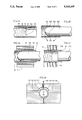
- FIG. 4 is a cutaway side view of prior art using layered rather than monolithic walls
- FIG. 5 is a cutaway side view of a monolithic wall with a ridged inside wall in an embodiment of this invention. It is positioned immediately beside the prior art which is so labeled for ease of comparison;
- FIG. 6 is a layout of co-extrusion construction of this invention. Stages of construction of the catheter in select embodiments are related to co-extrusion steps shown in FIGS. 6a through 6h.
- FIG. 6a is the first stage of production of the catheter showing a cross-section of the mandrel
- FIG. 6b is a stage of production at the first extrusion die which extrudes a first portion of the catheter wall
- FIG. 6c is the stage of production where one or more strands of inside reinforcement are wrapped onto the outside diameter of the first portion of the catheter wall;
- FIG. 6d shows a stage of production of the second extrusion die which is employed to extrude a second portion of the catheter wall
- FIG. 6c shows the production stage of the catheter tube being provided with friction reduction channels in accordance with the invention
- FIG. 6f is the production stage showing a third extrusion die employed to extrude additional molten catheter material infused relationship to the existing catheter wall;
- FIG. 6g shows a production step employing a linear positioner to position linear diagnostic components
- FIG. 6h is a production step showing the covering of the diagnostic components of the stage of FIG. 6g with additional material extruded from a fourth extrusion die;
- FIG. 7 is a section of etched mandrel of an in place type employed for particular spiral or opposite direction spiral embodiments of this invention.
- FIG. 8 is a section of a catheter that has been formed on the FIG. 7 mandrel
- FIG. 9 is a side view of a mandrel of the sliding type showing rotatable spiral forming and opposite direction spiral forming appendages
- FIG. 10 is a front view of the FIG. 9 illustration
- FIG. 11 is a cutaway sectional view of a catheter being formed on an in place heat expandable mandrel that is being heated from the outside to heat expand the mandrel and force inside walls of the catheter between reinforcement strands to form friction reduction channels in the inside walls;
- FIG. 12 is a sectional view of a catheter with varied density of reinforcement wrapping at select portions of catheters, such as at the distal end where a tip is attachable;
- FIG. 13 is a distal end view of a catheter showing reinforcement strands projecting from the catheter walls, particularly if heat were applied for purposes such as welding on a catheter tip without the manufacturing methods taught by this invention;
- FIG. 14 is a side view of a distal end of a catheter that has been stress relief cut selectively for relieving tension of reinforcement strands at a portion of the distal end to be heat welded to a catheter tip;
- FIG. 15 is a cutaway side view of a distal end of a catheter welded to a catheter tip
- FIG. 16 is a cutaway side view of a subsequent step of inside diameter surfacing welding and smooth welding of the catheter end and tip while heat is being dissipated at the outside diameter to avoid overheating of their matrices;
- FIG. 17 is a cutaway side view of a subsequent step of outside diameter surface welding and smooth welding of the catheter end and tip while heat is being dissipated with a cooling fluid at the inside diameter to avoid overheating their matrices;
- FIG. 18 is an alternative method of precision heating of the distal end of the catheter and the tip to achieve the final weld shown in FIG. 15 in a remote location with great precision;
- FIG. 19 is a cross-sectional end view of a cryogenically cooled clamping means in relationship to a cutting tool for forming a perfusion port without distorting structural integrity of the catheter;
- FIG. 20 is a layout illustration of a reinforcement strand being electrostatically coated with select materials in a fluidized bath as the reinforcement strand is being wrapped onto a catheter;
- FIG. 21 is a cross-sectional layout view of welding circumferential sections of a catheter to a tip progressively or sequentially in steps;
- FIG. 22 is an end view of a multiple strand reinforcement line with a large core member for select transmission of fluid, light or current;
- FIG. 23 is an end view of a multiple strand reinforcement line with a uniform diameter core.
- FIG. 1 A catheter 1 is provided with a handle 2 and a standard internally coned luer connector 3 at a proximal end 4 of the catheter 1.
- a distal end 5 of the catheter 1 has a catheter tip 6.
- the distal end 5 of the catheter can have a directional bend 7.
- the catheter 1 can be steered directionally by circumferentially positioning of the directional bend 7 with handle 2. This points the tip 6 into particular body lumens at their confluence with other body lumens and directs it also into particular portions of body lumens as desired by a practitioner.
- the catheter 1 In order to point the directional bend 7 precisely in a desired direction at a particular distance of entry of the catheter, it is essential that the catheter 1 not be flexible circumferentially. Yet it must be highly flexible linearly to follow body lumens without injuring them. Also to avoid bodily injury, the catheter tip 6 must be soft and pliable. Circumferential inflexibility is referred to as torque transmission because rotational torque of the handle is transferable directly to the tip 6, even though the catheter 1 may be flexed in various curves of body lumens. In addition, the directional bend must have linear flexibility, resilience and curvature adjustable to particular body conditions.
- reinforcement strands 8 are embedded in a monolithic wall 9 of a catheter 1.
- Monolithic describes a wall 9 formed without layers of embedding spiralled or cross spiralled strands in the wall. To accomplish this, the wall 9 is co-extruded from inside and outside of the strands while the material for the wall 9 is molten and fusible with the strands 8 included in it. The effect is the same as single extrusion of a monolithic wall with strands mixed in it as effectively as if the circumferential strands were particles in a hardenable liquid mixture. There are no layers to separate.
- Some walls have been referred to previously as being monolithic when outer layers have been applied after inner layers have hardened and reinforcement strands applied. Arguably, such a layering condition may be monolithic if bonding of the second layer is adequate. However, in the extremely small sizes involved, there is not sufficient area for multiple layers or for their effective bonding. Making walls thin enough to maximize use of space and still have adequate torque transmission and linear flexibility does not allow multiple layers that are effectively bonded to inside and outside diameters of spiralled reinforcement. If prior multiple layering can be termed monolithic, then this invention has a higher grade of monolithic walls.
- Friction reduction channels 10 are provided between bore surfaces 11 of a catheter bore 12. Bore ridges 11 decrease surface area of contact of instrumentation inserted in the catheter bore 12.
- the material with which the catheter 1 is constructed is impregnated with fluorine containing or silicon containing material for a solid lubrication effect.
- FIG. 4 Prior art is shown in FIG. 4 with an inside layer 13, a reinforcement layer 14 and an outside layer 15 applied later. This demonstrates a structure of prior art that has been referred to as being monolithic.
- FIG. 5 demonstrates reinforcement strands 8, in optionally a plurality of layers, embedded in a monolithic wall 9.
- Friction reduction channels 10 and bore surfaces 11 can be shaped selectively with the methods provided by this invention.
- the bore surfaces 11 are smooth welded flat between friction reduction channels 10.
- FIG. 6 comprises an entire page on its side and reading from left to right.
- a layout of a co-extrusion method 16 of this invention At the top of the sideways page is a layout of a co-extrusion method 16 of this invention.
- stages of production 17 At the bottom of the page are cross sections of stages of production 17 of a catheter 1.
- the stages of production 17 are referenced to particular steps of the co-extrusion method 16 by phantom lines.
- the stages of production 17 are production forms of the catheter 1 at the indicated steps of the co-extrusion method 16, subject to variation for different embodiments of the catheter 1 and of the co-extrusion method 16.
- a mandrel 18 which is shown in cross section 19 at the bottom of the page.
- This mandrel 18 is representative of a variety of well-known mandrels and mandrel systems that could be employed with this invention. It is also representative of particular mandrels explained by this invention.
- a first extrusion die 20 which extrudes a first portion of the catheter wall 21.
- a first wrapper 22 is employed to wrap one or more strands of inside reinforcement 23 onto the outside diameter of the first portion of the catheter wall 21.
- There can be one or more strands of inside reinforcement 23 which is shown with six strands being wrapped simultaneously.
- a second extrusion die 24 is employed to extrude a second portion of catheter wall 21.
- the second portion of the wall 21 becomes an indistinguishable, monolithic, fused addition to the catheter wall 21.
- the form of the catheter after the first extrusion die is a first stage catheter tube 25. It would be useable for some applications but not for the purposes intended by this invention. After wrapping the first stage catheter tube 25 with reinforcement material 23, there is no useable form of catheter because the reinforcement material is exposed in an unacceptable manner for medical purposes. After extrusion by the second extrusion die, however, there is a viable catheter referred to as a second stage catheter tube 26.
- the second stage catheter tube 26 can be provided with friction reduction channels 10 in accordance with the type of mandrel 18 and related practices being employed. Because the process could be terminated at this point for some embodiments of this invention, a first terminal 27 is illustrated by break lines in the catheter wall 21.
- the co-extrusion method 16 can be continued by maintaining molten heat of the catheter wall 21 and employing a second wrapper 28 for adding a second layer of reinforcement material 29 to the catheter wall 21. Then a third extrusion die 30 is employed to extrude additional molten catheter material in fused relationship to the existing catheter wall 21. The fused molten catheter wall 21 becomes thicker with the additional molten material added and with the additional reinforcement wrapped onto it. After further molten deposit by the third extrusion die 30, a third stage catheter tube 31 is formed. This is a more advanced embodiment of the invention. A second terminal 32 is shown to indicate optional termination of the co-extrusion method at this point. There can be additional wrappers and extrusion dies as long as there is a means for maintaining molten heat sufficient for fusion of the material added to the previous catheter material.
- Another desirable co-extrusion step for some applications is to employ a linear positioner 33 to position linear diagnostic, spring or other linear components 34 and then cover them with additional material extruded with a fourth extrusion die 35.
- This function can be accomplished either before the second wrapper 28 or after the third extrusion die 30.
- the sequence of the second wrapper 28 and the linear positioner 33 would be reversed. This would cause the second layer of reinforcement material 29 to secure the linear components 34 in the catheter wall 21.
- linear components 34 can be pressured against the outside of reinforcement material 29 while being covered with additional catheter material to comprise a fourth stage catheter tube 36.
- an in place mandrel 37 with etched spiral channels 38 and optional opposite direction spiral channels 39 can be employed to form reciprocally spiralled ridges 40 and 41 in a formed channel catheter tube 42.
- ridge peaks 43 form inside walls of the catheter tube 42 with low friction resistance to passage of instrumentation through the bore 12. With solid lubrication in the catheter material, friction resistance is particularly low.
- a sliding mandrel 44 with rotatable channel forming knob 45 and oppositely rotatable channel forming knob 46 as options can be employed to form inside diameters of catheters 1.
- the sliding mandrel can be any desired length which does not cause excessive friction.
- Heat can be added through the mandrel 44 in addition to being added externally.
- Rotation of the knobs 45 and 46 can be provided through a forward axle 47 having appropriate internal gearing for opposite rotation.
- a heat source 48 at the outside periphery of catheter walls 21 can be employed to cause a molten state of the walls 21 and to cause heat expansion of heat expandable in place mandrel 49. Expansion of the heat expandable mandrel 49 against the molten catheter walls 21 forces the walls 21 to deform outward radially and to form friction reduction channels 10 at sides of inside reinforcement strands 23. A slight increase in outside diameter of the walls 21 can result to compensate for outward travel in the formation of the friction reduction channels 10. Bore surfaces 11 are formed as spiralled ridges between the friction reduction channels 10.
- reinforcement strands 8 can be spiral wrapped and counter spiral wrapped onto the outside periphery of catheter walls 21.
- the spiral wrapping can be less dense at particular portions, such as at the distal end 5 where a tip is attached.
- catheter walls 21 are stress relief cut with selective wedge cuts 50 and linear cuts 51. This isolates circumferential pressure of the reinforcement strands 8 from a cut section of a distal end of walls 21.
- a catheter tip 6 that is welded to a distal end 5 of catheter walls 21 shows portions of the tip 6 extended into the linear cuts 50. To accomplish this without melting the matrix of the distal end 5 of the catheter walls 21 and without melting the tip 6, however, requires special methods.
- FIG. 18 shows an iron, or other suitable metal, receptor disk 52 located at some predetermined precise point within a stainless steel welding mandrel 53 for transferring heat to a limited area at the relief cut distal end 5 of the catheter walls 21 and a butt end 54 of the tip 6.
- Heat is applied, by any suitable means, only at the receptor disk 52 which extends only about one-half of the length of the stress relief cuts 50 and 51 and an approximately equal length of the tip 6 from its butt end 54. This provides a preliminary weld, leaving the other one-half of the relief cuts 55 unwelded.
- An inside surface weld and an outside surface weld with heat dissipation at opposite surfaces respectively are employed to finish the process of welding the tip 6 to the distal end 5 of the catheter 1.
- FIG. 16 shows the inside surface welding step of welding the tip 6 to the distal end 5 of the walls 21.
- a welding mandrel 56 is employed to apply heat to a slightly longer length of the walls 21 and the tip 6 at their inside diameter. Simultaneously, heat is dissipated through a cooling sheath 57 or other heat sink in heat conductive relationship to the outside of the walls 21 and the tip 6.
- FIG. 17 shows the outside surface welding step of welding the tip 6 to the distal end 5 of the walls 21.
- An outside circumferential welder 58 is employed to apply welding heat to the outside peripheries of walls 21 and tip 6 while heat is being dissipated directly by a coolant such as cryogenic nitrogen supplied through a coolant tube 59.
- perfusion ports can be constructed in walls 21 with a cutting or punching tool 60 without destroying structural integrity of either the catheter material or reinforcement strands when friction heat from a cutting process is dissipated from the walls 21 adequately.
- a clamp block 61 having coolant channels 62 at each side and a cooling enclosure 63 at the outside periphery of the walls 21 which are positional in a clamp enclosure 64. After flowing in through the coolant channels 62 and around a portion of the walls 21 in the cooling enclosure 63, coolant then passes through a cutting enclosure 65. This directs the coolant lastly in contact with the cutting tool 60.
- reinforcement strands 8 to be wrapped onto a mandrel 18 as either inside reinforcement 23 or second layer reinforcement 29 can be coated with bonding material while being wrapped. This is accomplished by passing the strands 8 through a fluidized powder bed 66 and applying electrostatic charge through a charger 67.
- a series of axial welds or a continuously rotating weld at the outside periphery of walls 21 can be employed to prevent melting of the entire walls at any time. This is accomplished by positioning a welding heat source 68 at a portion of the outside periphery of walls 21. Then the welding heat source 68 is rotated for either a series of axial welds or rotated continuously as indicated by broken line illustrations. Heat can be dissipated through a fluid or solid cooling medium 69 inside of the walls 21.
- reinforcement strands 8 can be wound into lines 70 with multiple strands.
- the principles applicable are similar to those employed in cable winding because the materials have similar characteristics although the sizes are much smaller.
- Single strands can be as small in diameter as 0.010 inches, about the size of a human hair. The smaller in diameter, the more flexible a strand can be and still provide strength when there are multiple strands wound together like a cable or yarn.
- a center core 71 can be larger than other strands 72.
- a wide variety of alternative lines 70 can be provided.
- the center core can be a glass fiber for fiber optics, a separate catheter lumen or a copper wire for current conductivity, for example.
- all of the reinforcement strands 8 in a uniform strand line 73 can be the same diameter.
- Either or all of the strands can be of a type to provide some diagnostic function such as light conductance and current conductance for internal television.
- small strands of metal, glass or synthetic material wound into cable are superior to single larger strands.
- they also allow catheter material flow and set between strands. This results in high bonding strength in the ultra thin, high torque walls of catheters constructed in accordance with the teachings of this invention.
Abstract
A high torque, thin walled guiding catheter has resilient reinforcement material (8, 23, 29, 70, 73) integrally spiraled or braided into monolithic walls (21) of flexible material. A solid lubricant, also referred to as dry lubricant, comprised of either special fluorine containing materials or polymeric organic silicon compounds is embedded into interior and exterior wall surfaces of the catheters. Smooth interior walls (11) are channeled (10) to decrease friction resistance, to trap resistance particles and to dissipate friction heat in the high ratio of surface area to cross-sectional area of small catheters. Number of spirals or braids of reinforcement strands per unit of length, number of layers of strands of the catheters, catheter diameter and progressiveness thereof are designedly different for separate portions of particular catheters. Catheter tips (6) are weldable immediately adjacent to select density of strands of reinforcement material. Perfusion ports are weldable where desired. Directional bends (7) are positional selectively at distal ends (5) of the catheters (1). Methods for manufacture and modification with co-extrusion, miniature milling and welding while maintaining structural integrity with monolithic wall structure are described.
Description
I. Field of the Invention
The present invention relates generally to the field of catheters. More particularly it relates to guiding catheters having torque transmittal guidance walls that are flexible linearly but not circumferentially and that are neither collapsible nor kinkable. It is particularly suited as a vascular catheter.
II. Description of the Prior Art
Vascular catheters and some other types of catheters requiring remote guidance of insertion from outside of a patient have fine spiralled or braided metallic or non-metallic strands of reinforcement material in thin cylindrical walls of flexible catheter tubing. The catheter body must (a) contain fluid pressures up to 1,000 psi, (b) transmit rotational torque accurately from a proximal end outside of a patient to a distal end inside of the patient, (c) prevent collapse, kinking or alteration of conveyance area of the catheter, (d) convey electrical current or sound wave energy from end-to-end of the catheter and yet, (e) flex sufficiently not to injure bodily tissues. Diagnostic instrumentation, traceable fluids, medicine and body fluids must be conveyed through the catheter lumen effectively. Total diameter of the catheter tubing, however, is often less than one-tenth of an inch.
Guidance of such catheters within vascular and other body channels is achieved usually by selectively slight rotation of the catheter with a small handle at the proximal end. At the distal end near a non-injurious tip of the catheter inside of the patient, there is generally a curved directional bend. The slight rotation of the catheter points this directional bend precisely in a desired circumferential direction at a particular position of confluence or other physical condition of the body lumens or channels. This directs or guides insertional advancement of the catheter into desired body channels or lumens. Other guidance means employ unbent catheters in combination with various steerable tips.
A variety of problems have occurred with these small guiding catheters and related components previously. One problem has been a tendency of reinforcement strands to separate from polymer or various flexible materials from which the body of the catheter tubing is constructed. This destroys rotational torque transmittal capacity and leaves the catheter subject to kinking, collapse and general failure of its design requirements.
Another problem has been insufficient lubricity of inside catheter walls for conveyance of instrumentation, liquids and slurries of diagnostic and medicinal materials with low viscosity. Outside walls of catheters also have had inadequate lubricity for passage in and out of relatively small body channels.
Another problem has been inadequately resilient directional bends at distal ends of catheters. Some have been too rigid. Others have been the opposite without sufficient resilience memory to regain a directional curve after being straightened or bent differently in various portions of body channels.
A relatively common problem has been incapacity of a catheter having sufficient linear flexibility to convey rotational torque between a reinforced catheter body and a desirably flexible or soft catheter tip.
Still another problem has been incapacity of previous catheters to be drilled or welded to form side apertures referred to as perfusion ports. The walls of present catheters delaminate, separate and fail from heat of either drilling or welding.
Solving these and other problems has inspired this invention.
Different but pertinent catheter technology is described in the following patent documents.
______________________________________
NATION  NUMBER      DATE        NAME
______________________________________
Euro.   0 421 650 A1
                    Apr. 10, 1991
                                Frassica
U.S.    4,764,324   Aug. 16, 1988
                                Burnham
U.S.    4,676,229   Jun. 30, 1987
                                Krasnicki et al
U.S.    4,577,543   Mar. 25, 1986
                                Wilson
U.S.    4,531,943   Jul. 30, 1985
                                Van Tassel et al
U.S.    4,425,919   Jan. 17, 1984
                                Alston, Jr. et al
U.S.    3,924,632   Dec. 9, 1975
                                Cook
U.S.    3,498,286   Mar. 3, 1970
                                Polanyi et al
______________________________________
The Frassica European Patent taught rolled layers of polymeric film interspersed with reinforcement materials and various instrumentation elements. High versatility of construction was a main feature of that patent. A wide variety of features could be provided at various portions of the catheter body. Problems, however, were tendency of the layers to separate, large diameter, ridges at linear and circumferential joints and high production cost to achieve variations. Also different from this invention, it could not be customized by mere programming of most of its features into a production process.
The Burnham Patent taught a single extrusion method based on tensioning reinforcement strands being wound around heat softened thermoplastic catheter walls to draw the strands radially into the walls after they were formed. Different from this invention, however, it was not a process that applied catheter wall material inside and outside of the reinforcement strands during a simultaneous co-extrusion and strand winding process to form monolithic walls with tightly woven reinforcement strands. It had no solid lubrication in its walls. There was no wall interruption or channelling for friction reduction. Its reinforcement was not sufficiently variable linearly. There was no means for welding tips in close proximity to torque transmittal reinforcement strands to transmit torque effectively or to prevent tips from coming off inside of patients. Nor was there means for providing profusion ports and other features without destroying structural integrity of the catheter.
The Krasnicki et al Patent described an endoscope biopsy channel with a lubricous inner layer bounded by high strength wire helically wound around it. A soft outer layer provided protection against injury of tissue. Flexible material filled space between wire strands and between the lubricous inner wall and the soft outer wall. That catheter was not producible with sufficiently small diameters and thin walls. Separate walls inside and outside of helical windings consume too much space for small diameter production or for space efficient large diameter catheters.
The Wilson Patent taught a method to form what it referred to as a monolithic construction of cannulae that could be used for a catheter. Reinforcement strands were wound around the outside of a catheter tube that was then heated to cause the strands to adhere to the outside of the tube. In an optional subsequent step of the method, an additional layer of material was extruded onto the outside of the reinforcement strands. Unlike this invention, however, that method was not a simultaneous co-extrusion and wrapping process that formed a more integrated monolithic wall with less likelihood of separation. There was no solid lubricant at surfaces nor friction reduction channels between solid lubricant surfaces. There was no method for attaching integral tips nor providing profusion ports without destroying structural integrity.
The Van Tassel et al Patent taught the attachment of a soft balloon like tip to ends of catheters. But it was not a method that could be used for attachment to reinforced walls because it required step cutting of the catheter wall.
The Alston, Jr. et al Patent positioned flat wire braiding between layers of material. This required thick walls in proportion to diameter of catheters. Separation of the layers was problematic for thin walls with that type of construction. It was not a monolithic type of wall taught by this invention.
The Cook Patent employed conventional sandwiching of fiberglass woven roving between plastic layers of tubing. Walls were far too thick for the conveyance efficiency required for current medical practices.
The Polanyi et al Patent combined a wide variety of catheter features in a catheter wall. But the constructional form was far too thick and the cost of construction too high in comparison to present catheters. It was one of the first catheters to utilize fiber optics, but in forms that have been superseded with smaller and more efficient fiber optics and diagnostic equipment made possible with this invention. Its walls and linear components would separate if made sufficiently thin for current catheter applications.
In accordance with the present invention, it is contemplated that one objective of this invention is to provide a catheter with a high ratio of torque transmittal capacity from end-to-end for accurate and reliable rotational positioning of a guiding tip at a distal end of the catheter.
Another objective is to provide selective resilience and circumferential torque transmission at different linear portions of a catheter.
Another objective is to provide high lubricity of both inside and outside peripheral surfaces of a catheter.
Another objective is to provide perfusion ports at select portions of a catheter without weakening torque transmission, cylindrical integrity, structural integrity, flexibility or resilience of a catheter.
Another objective is to provide a catheter having thinner walls and a smaller outside diameter in proportion to inside diameter than present catheters.
Another objective is to provide a soft and smooth catheter tip immediately at the distal end of either progressively decreased or continued reinforcement density of a catheter.
Yet another objective of this invention is to provide methods for constructing catheters having characteristics provided by this invention.
This invention accomplishes the above and other objectives with a catheter having strands of resilient reinforcement material integrally spiraled or braided into monolithic walls of flexible material. A solid lubricant, also referred to as dry lubricant, comprised of either special fluorine containing materials or polymeric organic silicon compounds is embedded into interior and exterior wall surfaces of the catheters. Smooth interior walls are channeled to decrease friction resistance, to trap resistance particles and to dissipate friction heat in the high ratio of surface area to cross-sectional area of small catheters. Number of spirals or braids of reinforcement strands per unit of length, number of layers of strands of the catheters, catheter diameter and progressiveness thereof are designedly different for separate portions of particular catheters. Catheter tips are weldable immediately adjacent to select density of strands of reinforcement material. Perfusion ports are weldable where desired. Directional bends are positional selectively at distal ends of the catheters. Methods for manufacture and modification with co-extrusion, miniature milling and welding while maintaining structural integrity with monolithic wall structure are described.
Other objects, advantages and capabilities of the invention will become apparent from the following description taken in conjunction with the accompanying drawings showing preferred embodiments of the invention.
FIG. 1 is a cutaway side view of a luer and proximal end section of a catheter using this invention;
FIG. 2 is a distal end and tip of a catheter using this invention;
FIG. 3 is a cutaway sectional view of a catheter with reinforced monolithic walls in an embodiment of this invention;
FIG. 4 is a cutaway side view of prior art using layered rather than monolithic walls;
FIG. 5 is a cutaway side view of a monolithic wall with a ridged inside wall in an embodiment of this invention. It is positioned immediately beside the prior art which is so labeled for ease of comparison;
FIG. 6 is a layout of co-extrusion construction of this invention. Stages of construction of the catheter in select embodiments are related to co-extrusion steps shown in FIGS. 6a through 6h.
FIG. 6a is the first stage of production of the catheter showing a cross-section of the mandrel;
FIG. 6b is a stage of production at the first extrusion die which extrudes a first portion of the catheter wall;
FIG. 6c is the stage of production where one or more strands of inside reinforcement are wrapped onto the outside diameter of the first portion of the catheter wall;
FIG. 6d shows a stage of production of the second extrusion die which is employed to extrude a second portion of the catheter wall;
FIG. 6c shows the production stage of the catheter tube being provided with friction reduction channels in accordance with the invention;
FIG. 6f is the production stage showing a third extrusion die employed to extrude additional molten catheter material infused relationship to the existing catheter wall;
FIG. 6g shows a production step employing a linear positioner to position linear diagnostic components;
FIG. 6h is a production step showing the covering of the diagnostic components of the stage of FIG. 6g with additional material extruded from a fourth extrusion die;
FIG. 7 is a section of etched mandrel of an in place type employed for particular spiral or opposite direction spiral embodiments of this invention;
FIG. 8 is a section of a catheter that has been formed on the FIG. 7 mandrel;
FIG. 9 is a side view of a mandrel of the sliding type showing rotatable spiral forming and opposite direction spiral forming appendages;
FIG. 10 is a front view of the FIG. 9 illustration;
FIG. 11 is a cutaway sectional view of a catheter being formed on an in place heat expandable mandrel that is being heated from the outside to heat expand the mandrel and force inside walls of the catheter between reinforcement strands to form friction reduction channels in the inside walls;
FIG. 12 is a sectional view of a catheter with varied density of reinforcement wrapping at select portions of catheters, such as at the distal end where a tip is attachable;
FIG. 13 is a distal end view of a catheter showing reinforcement strands projecting from the catheter walls, particularly if heat were applied for purposes such as welding on a catheter tip without the manufacturing methods taught by this invention;
FIG. 14 is a side view of a distal end of a catheter that has been stress relief cut selectively for relieving tension of reinforcement strands at a portion of the distal end to be heat welded to a catheter tip;
FIG. 15 is a cutaway side view of a distal end of a catheter welded to a catheter tip;
FIG. 16 is a cutaway side view of a subsequent step of inside diameter surfacing welding and smooth welding of the catheter end and tip while heat is being dissipated at the outside diameter to avoid overheating of their matrices;
FIG. 17 is a cutaway side view of a subsequent step of outside diameter surface welding and smooth welding of the catheter end and tip while heat is being dissipated with a cooling fluid at the inside diameter to avoid overheating their matrices;
FIG. 18 is an alternative method of precision heating of the distal end of the catheter and the tip to achieve the final weld shown in FIG. 15 in a remote location with great precision;
FIG. 19 is a cross-sectional end view of a cryogenically cooled clamping means in relationship to a cutting tool for forming a perfusion port without distorting structural integrity of the catheter;
FIG. 20 is a layout illustration of a reinforcement strand being electrostatically coated with select materials in a fluidized bath as the reinforcement strand is being wrapped onto a catheter;
FIG. 21 is a cross-sectional layout view of welding circumferential sections of a catheter to a tip progressively or sequentially in steps;
FIG. 22 is an end view of a multiple strand reinforcement line with a large core member for select transmission of fluid, light or current; and
FIG. 23 is an end view of a multiple strand reinforcement line with a uniform diameter core.
Referring to the drawings wherein like reference numerals designate corresponding parts throughout the several figures, reference is made first to FIG. 1. A catheter 1 is provided with a handle 2 and a standard internally coned luer connector 3 at a proximal end 4 of the catheter 1.
Referring to FIGS. 1 and 2, a distal end 5 of the catheter 1 has a catheter tip 6. The distal end 5 of the catheter can have a directional bend 7. The catheter 1 can be steered directionally by circumferentially positioning of the directional bend 7 with handle 2. This points the tip 6 into particular body lumens at their confluence with other body lumens and directs it also into particular portions of body lumens as desired by a practitioner.
In order to point the directional bend 7 precisely in a desired direction at a particular distance of entry of the catheter, it is essential that the catheter 1 not be flexible circumferentially. Yet it must be highly flexible linearly to follow body lumens without injuring them. Also to avoid bodily injury, the catheter tip 6 must be soft and pliable. Circumferential inflexibility is referred to as torque transmission because rotational torque of the handle is transferable directly to the tip 6, even though the catheter 1 may be flexed in various curves of body lumens. In addition, the directional bend must have linear flexibility, resilience and curvature adjustable to particular body conditions. Meeting these requirements with a thin walled catheter having a diameter of a tenth of an inch or less and being able to pass diagnostic instrumentation and fluids through them without rupturing them with frictional resistance have been technical problems that have been solved along with other problems by this invention.
Referring now to FIG. 3, reinforcement strands 8 are embedded in a monolithic wall 9 of a catheter 1. Monolithic describes a wall 9 formed without layers of embedding spiralled or cross spiralled strands in the wall. To accomplish this, the wall 9 is co-extruded from inside and outside of the strands while the material for the wall 9 is molten and fusible with the strands 8 included in it. The effect is the same as single extrusion of a monolithic wall with strands mixed in it as effectively as if the circumferential strands were particles in a hardenable liquid mixture. There are no layers to separate.
Some walls have been referred to previously as being monolithic when outer layers have been applied after inner layers have hardened and reinforcement strands applied. Arguably, such a layering condition may be monolithic if bonding of the second layer is adequate. However, in the extremely small sizes involved, there is not sufficient area for multiple layers or for their effective bonding. Making walls thin enough to maximize use of space and still have adequate torque transmission and linear flexibility does not allow multiple layers that are effectively bonded to inside and outside diameters of spiralled reinforcement. If prior multiple layering can be termed monolithic, then this invention has a higher grade of monolithic walls.
Prior art is shown in FIG. 4 with an inside layer 13, a reinforcement layer 14 and an outside layer 15 applied later. This demonstrates a structure of prior art that has been referred to as being monolithic.
Immediately next to it for comparison, FIG. 5 demonstrates reinforcement strands 8, in optionally a plurality of layers, embedded in a monolithic wall 9. Friction reduction channels 10 and bore surfaces 11 can be shaped selectively with the methods provided by this invention. In this illustration, the bore surfaces 11 are smooth welded flat between friction reduction channels 10.
Reference is made now to FIG. 6, which comprises an entire page on its side and reading from left to right. At the top of the sideways page is a layout of a co-extrusion method 16 of this invention. At the bottom of the page are cross sections of stages of production 17 of a catheter 1. The stages of production 17 are referenced to particular steps of the co-extrusion method 16 by phantom lines. The stages of production 17 are production forms of the catheter 1 at the indicated steps of the co-extrusion method 16, subject to variation for different embodiments of the catheter 1 and of the co-extrusion method 16.
Starting at the top left corner is a mandrel 18, which is shown in cross section 19 at the bottom of the page. This mandrel 18 is representative of a variety of well-known mandrels and mandrel systems that could be employed with this invention. It is also representative of particular mandrels explained by this invention. Following the mandrel 18 is a first extrusion die 20 which extrudes a first portion of the catheter wall 21. A first wrapper 22 is employed to wrap one or more strands of inside reinforcement 23 onto the outside diameter of the first portion of the catheter wall 21. There can be one or more strands of inside reinforcement 23 which is shown with six strands being wrapped simultaneously. Then a second extrusion die 24 is employed to extrude a second portion of catheter wall 21. The second portion of the wall 21 becomes an indistinguishable, monolithic, fused addition to the catheter wall 21. The form of the catheter after the first extrusion die is a first stage catheter tube 25. It would be useable for some applications but not for the purposes intended by this invention. After wrapping the first stage catheter tube 25 with reinforcement material 23, there is no useable form of catheter because the reinforcement material is exposed in an unacceptable manner for medical purposes. After extrusion by the second extrusion die, however, there is a viable catheter referred to as a second stage catheter tube 26. The second stage catheter tube 26 can be provided with friction reduction channels 10 in accordance with the type of mandrel 18 and related practices being employed. Because the process could be terminated at this point for some embodiments of this invention, a first terminal 27 is illustrated by break lines in the catheter wall 21.
The co-extrusion method 16 can be continued by maintaining molten heat of the catheter wall 21 and employing a second wrapper 28 for adding a second layer of reinforcement material 29 to the catheter wall 21. Then a third extrusion die 30 is employed to extrude additional molten catheter material in fused relationship to the existing catheter wall 21. The fused molten catheter wall 21 becomes thicker with the additional molten material added and with the additional reinforcement wrapped onto it. After further molten deposit by the third extrusion die 30, a third stage catheter tube 31 is formed. This is a more advanced embodiment of the invention. A second terminal 32 is shown to indicate optional termination of the co-extrusion method at this point. There can be additional wrappers and extrusion dies as long as there is a means for maintaining molten heat sufficient for fusion of the material added to the previous catheter material.
Another desirable co-extrusion step for some applications is to employ a linear positioner 33 to position linear diagnostic, spring or other linear components 34 and then cover them with additional material extruded with a fourth extrusion die 35. This function can be accomplished either before the second wrapper 28 or after the third extrusion die 30. The sequence of the second wrapper 28 and the linear positioner 33 would be reversed. This would cause the second layer of reinforcement material 29 to secure the linear components 34 in the catheter wall 21. When positioned after the third extrusion die 30, linear components 34 can be pressured against the outside of reinforcement material 29 while being covered with additional catheter material to comprise a fourth stage catheter tube 36.
Referring to FIGS. 7 and 8, an in place mandrel 37 with etched spiral channels 38 and optional opposite direction spiral channels 39 can be employed to form reciprocally spiralled ridges 40 and 41 in a formed channel catheter tube 42. After the in place mandrel 37 is removed by disintegration or other means, ridge peaks 43 form inside walls of the catheter tube 42 with low friction resistance to passage of instrumentation through the bore 12. With solid lubrication in the catheter material, friction resistance is particularly low.
Referring to FIGS. 9 and 10, a sliding mandrel 44 with rotatable channel forming knob 45 and oppositely rotatable channel forming knob 46 as options can be employed to form inside diameters of catheters 1. The sliding mandrel can be any desired length which does not cause excessive friction. Heat can be added through the mandrel 44 in addition to being added externally. Rotation of the knobs 45 and 46 can be provided through a forward axle 47 having appropriate internal gearing for opposite rotation.
Referring to FIG. 11, a heat source 48 at the outside periphery of catheter walls 21 can be employed to cause a molten state of the walls 21 and to cause heat expansion of heat expandable in place mandrel 49. Expansion of the heat expandable mandrel 49 against the molten catheter walls 21 forces the walls 21 to deform outward radially and to form friction reduction channels 10 at sides of inside reinforcement strands 23. A slight increase in outside diameter of the walls 21 can result to compensate for outward travel in the formation of the friction reduction channels 10. Bore surfaces 11 are formed as spiralled ridges between the friction reduction channels 10.
Referring to FIG. 12, reinforcement strands 8 can be spiral wrapped and counter spiral wrapped onto the outside periphery of catheter walls 21. The spiral wrapping can be less dense at particular portions, such as at the distal end 5 where a tip is attached.
Referring to FIGS. 13 and 14, heating of a distal end 5 of the catheter walls 21 to weld on a catheter tip 6 can cause the catheter material to soften and allow ends of reinforcement strands 8 to protrude as illustrated in FIG. 13. To avoid this and to cause a reliable weld of a tip 6 to a distal end 5 of a catheter 1, catheter walls 21 are stress relief cut with selective wedge cuts 50 and linear cuts 51. This isolates circumferential pressure of the reinforcement strands 8 from a cut section of a distal end of walls 21.
In FIG. 15, a catheter tip 6 that is welded to a distal end 5 of catheter walls 21 shows portions of the tip 6 extended into the linear cuts 50. To accomplish this without melting the matrix of the distal end 5 of the catheter walls 21 and without melting the tip 6, however, requires special methods.
FIG. 18 shows an iron, or other suitable metal, receptor disk 52 located at some predetermined precise point within a stainless steel welding mandrel 53 for transferring heat to a limited area at the relief cut distal end 5 of the catheter walls 21 and a butt end 54 of the tip 6. Heat is applied, by any suitable means, only at the receptor disk 52 which extends only about one-half of the length of the stress relief cuts 50 and 51 and an approximately equal length of the tip 6 from its butt end 54. This provides a preliminary weld, leaving the other one-half of the relief cuts 55 unwelded. An inside surface weld and an outside surface weld with heat dissipation at opposite surfaces respectively are employed to finish the process of welding the tip 6 to the distal end 5 of the catheter 1.
FIG. 16 shows the inside surface welding step of welding the tip 6 to the distal end 5 of the walls 21. A welding mandrel 56 is employed to apply heat to a slightly longer length of the walls 21 and the tip 6 at their inside diameter. Simultaneously, heat is dissipated through a cooling sheath 57 or other heat sink in heat conductive relationship to the outside of the walls 21 and the tip 6.
FIG. 17 shows the outside surface welding step of welding the tip 6 to the distal end 5 of the walls 21. An outside circumferential welder 58 is employed to apply welding heat to the outside peripheries of walls 21 and tip 6 while heat is being dissipated directly by a coolant such as cryogenic nitrogen supplied through a coolant tube 59.
Referring to FIG. 19, perfusion ports can be constructed in walls 21 with a cutting or punching tool 60 without destroying structural integrity of either the catheter material or reinforcement strands when friction heat from a cutting process is dissipated from the walls 21 adequately. This is accomplished with a clamp block 61 having coolant channels 62 at each side and a cooling enclosure 63 at the outside periphery of the walls 21 which are positional in a clamp enclosure 64. After flowing in through the coolant channels 62 and around a portion of the walls 21 in the cooling enclosure 63, coolant then passes through a cutting enclosure 65. This directs the coolant lastly in contact with the cutting tool 60.
Referring to FIG. 20, reinforcement strands 8 to be wrapped onto a mandrel 18 as either inside reinforcement 23 or second layer reinforcement 29 can be coated with bonding material while being wrapped. This is accomplished by passing the strands 8 through a fluidized powder bed 66 and applying electrostatic charge through a charger 67.
Referring to FIG. 21, a series of axial welds or a continuously rotating weld at the outside periphery of walls 21 can be employed to prevent melting of the entire walls at any time. This is accomplished by positioning a welding heat source 68 at a portion of the outside periphery of walls 21. Then the welding heat source 68 is rotated for either a series of axial welds or rotated continuously as indicated by broken line illustrations. Heat can be dissipated through a fluid or solid cooling medium 69 inside of the walls 21.
Referring to FIG. 22, reinforcement strands 8 can be wound into lines 70 with multiple strands. The principles applicable are similar to those employed in cable winding because the materials have similar characteristics although the sizes are much smaller. Single strands can be as small in diameter as 0.010 inches, about the size of a human hair. The smaller in diameter, the more flexible a strand can be and still provide strength when there are multiple strands wound together like a cable or yarn. Like cable technology also, a center core 71 can be larger than other strands 72. A wide variety of alternative lines 70 can be provided. The center core can be a glass fiber for fiber optics, a separate catheter lumen or a copper wire for current conductivity, for example.
Referring to FIG. 23, all of the reinforcement strands 8 in a uniform strand line 73 can be the same diameter. Either or all of the strands can be of a type to provide some diagnostic function such as light conductance and current conductance for internal television. When used only for resilience to provide high torque transmission, small strands of metal, glass or synthetic material wound into cable are superior to single larger strands. In addition to providing greater strength, resilience and flexibility, they also allow catheter material flow and set between strands. This results in high bonding strength in the ultra thin, high torque walls of catheters constructed in accordance with the teachings of this invention.
A new and useful torque transmittal catheter having been described, all such modifications, adaptations, substitutions of equivalents, applications and forms thereof as described by the following claims are included in this invention.
Various modifications may be made of the invention without departing from the scope thereof and it is desired, therefore, that only such limitations shall be placed thereon as are imposed by the prior art and which are set forth in the appended claims.
Claims (16)
1. A catheter having:
strands of resilient reinforcement material having a structural memory embedded in monolithic catheter walls of flexible material,
the reinforcement material being select strands of resilient material positioned in select spiralled relationship within the monolithic walls,
linear diagnostic communication members positioned in the monolithic walls,
solid lubricant material on inside and outside peripheral surfaces of the catheter walls,
friction reduction channels in the inside peripheral surfaces of the catheter walls,
the reinforcement material being a plurality of layers of multiple strand resilient lines spiral braided in oppositely spiralled relationship within the monolithic walls, and having select variation of density of helical spirals per linear distance within the catheter.
2. A catheter according to claim 1 and further comprising:
linear reinforcement members positioned in the monolithic walls.
3. A catheter according to claim 2 wherein the linear reinforcement members are resilient.
4. A catheter according to claim 3 wherein at least one perfusion port positioned selectively in a wall of the catheter.
5. A catheter having:
strands of resilient reinforcement material having a structural memory embedded in monolithic catheter walls of flexible material,
the reinforcement material being select strands of resilient material positioned in select spiralled relationship within the monolithic walls,
linear diagnostic communication members positioned in the monolithic walls,
solid lubricant material on inside and outside peripheral surfaces of the catheter walls,
friction reduction channels in the inside peripheral surfaces of the catheter walls,
the reinforcement material being a plurality of layers of multiple strand resilient lines positioned concentrically with oppositely spiralled multiple strand resilient lines stacked circumferentially within the monolithic catheter walls, and having select variation of density of helical spirals per linear distance within the catheter.
6. A catheter according to claim 5 and further comprising:
linear reinforcement members positioned in the monolithic walls.
7. A catheter according to claim 6 wherein the linear reinforcement members are resilient.
8. A catheter according to claim 7 wherein at least one perfusion port positioned selectively in a wall of the catheter.
9. A catheter having:
strands of reinforcement material embedded in monolithic catheter walls of flexible material,
solid lubricant material on inside and outside peripheral surfaces of the catheter walls,
friction reduction channels in the inside peripheral surfaces of the catheter walls, and
wherein the friction reduction channels are between opposite directional helical ridges between braided solid lubricant covered opposite directional helical reinforcement members at inside peripheral surfaces of the catheter.
10. A catheter having:
strands of reinforcement material embedded in monolithic catheter walls of flexible material,
solid lubricant material on inside and outside of peripheral surfaces of the catheter walls,
friction reduction channels in the inside peripheral surfaces of the catheter walls, and
wherein the friction reduction channels are between opposite direction helical ridges in solid lubricant covered catheter material at inside peripheral surfaces of the catheter.
11. A catheter having:
strands of reinforcement material embedded in monolithic catheter walls of flexible material,
solid lubricant material on inside and outside peripheral surfaces of the catheter walls,
friction reduction channels in the inside peripheral surfaces of the catheter walls,
the reinforcement material being select strands of resilient material positioned in select spiralled relationship within the monolithic walls,
at least one stress relief cut in a distal end of the catheter,
a tip welded to the distal end of the catheter,
the density of spirals of the reinforcement material being decreased selectively in proximity of the distal end of the catheter,
at least one linear member in the monolithic wall proximate the distal end of the catheter.
12. A catheter according to claim 11 wherein the at least one linear member is selectively bendable to provide a bendable tip section of the catheter.
13. A catheter according to claim 11 wherein the at least one linear member is selectively resilient and bendable in a desired resilient curve to provide a curved resilient tip of the catheter.
14. A catheter according to claim 11 wherein the solid lubricant is a fluorine containing material.
15. A catheter according to claim 11 wherein the solid lubricant is a polymeric organic silicon material.
16. A catheter according to claim 11 wherein the friction reduction channels are helical voids between catheter material containing solid lubricant on helical reinforcement members at inside peripheral surfaces of the catheter.
Priority Applications (4)
| Application Number | Priority Date | Filing Date | Title |
|---|---|---|---|
| US07/881,422 US5334169A (en) | 1992-05-11 | 1992-05-11 | Reinforced catheter with thin monolithic walls |
| EP93911174A EP0639089A4 (en) | 1992-05-11 | 1993-05-10 | Reinforced catheter and method of manufacturing. |
| PCT/US1993/004370 WO1993023105A1 (en) | 1992-05-11 | 1993-05-10 | Reinforced catheter and method of manufacturing |
| US08/116,349 US5558737A (en) | 1992-05-11 | 1993-09-03 | Method of welding a tip to a catheter |
Applications Claiming Priority (1)
| Application Number | Priority Date | Filing Date | Title |
|---|---|---|---|
| US07/881,422 US5334169A (en) | 1992-05-11 | 1992-05-11 | Reinforced catheter with thin monolithic walls |
Related Child Applications (1)
| Application Number | Title | Priority Date | Filing Date |
|---|---|---|---|
| US08/116,349 Division US5558737A (en) | 1992-05-11 | 1993-09-03 | Method of welding a tip to a catheter |
Publications (1)
| Publication Number | Publication Date |
|---|---|
| US5334169A true US5334169A (en) | 1994-08-02 |
Family
ID=25378449
Family Applications (2)
| Application Number | Title | Priority Date | Filing Date |
|---|---|---|---|
| US07/881,422 Expired - Fee Related US5334169A (en) | 1992-05-11 | 1992-05-11 | Reinforced catheter with thin monolithic walls |
| US08/116,349 Expired - Fee Related US5558737A (en) | 1992-05-11 | 1993-09-03 | Method of welding a tip to a catheter |
Family Applications After (1)
| Application Number | Title | Priority Date | Filing Date |
|---|---|---|---|
| US08/116,349 Expired - Fee Related US5558737A (en) | 1992-05-11 | 1993-09-03 | Method of welding a tip to a catheter |
Country Status (3)
| Country | Link |
|---|---|
| US (2) | US5334169A (en) |
| EP (1) | EP0639089A4 (en) |
| WO (1) | WO1993023105A1 (en) |
Cited By (108)
| Publication number | Priority date | Publication date | Assignee | Title |
|---|---|---|---|---|
| WO1996028208A1 (en) * | 1995-03-14 | 1996-09-19 | Mallinckrodt Medical, Inc. | Catheters with reinforced filaments |
| US5571073A (en) * | 1994-01-28 | 1996-11-05 | Cordis Corporation | Catheter flexible tip assembly |
| WO1996038091A1 (en) * | 1995-06-02 | 1996-12-05 | Surgical Design Corporation | Phacoemulsification handpiece, sleeve, and tip |
| US5591142A (en) * | 1993-04-20 | 1997-01-07 | Cordis Corporation | Catheter with wire reinforcement having good electrical conductivity |
| WO1997006845A1 (en) * | 1995-08-14 | 1997-02-27 | Act Medical, Inc. | Catheter |
| US5647846A (en) * | 1995-05-17 | 1997-07-15 | Scimed Life Systems, Inc. | Catheter having geometrically shaped surface and method of manufacture |
| US5662622A (en) * | 1995-04-04 | 1997-09-02 | Cordis Corporation | Intravascular catheter |
| US5667499A (en) * | 1994-10-04 | 1997-09-16 | Scimed Life Systems, Inc. | Guide catheter unibody |
| US5680873A (en) * | 1995-03-02 | 1997-10-28 | Scimed Life Systems, Inc. | Braidless guide catheter |
| US5685841A (en) * | 1995-08-14 | 1997-11-11 | Mackool; Richard J. | Support for fluid infusion tube for use during eye surgery |
| US5704926A (en) * | 1994-11-23 | 1998-01-06 | Navarre Biomedical, Ltd. | Flexible catheter |
| US5722395A (en) * | 1991-09-12 | 1998-03-03 | The United States Of America As Represented By The Department Of Health And Human Services | Ultra thin walled wire reinforced endotracheal tubing |
| US5730733A (en) * | 1995-06-01 | 1998-03-24 | Scimed Life Systems, Inc. | Flow assisted catheter |
| US5755704A (en) * | 1996-10-29 | 1998-05-26 | Medtronic, Inc. | Thinwall guide catheter |
| EP0843618A1 (en) * | 1995-07-14 | 1998-05-27 | Localmed, Inc. | Method and system for reduced friction introduction of coaxial catheters |
| US5776115A (en) * | 1996-01-17 | 1998-07-07 | Becton Dickinson And Company | Catheter having a gear-shaped lumen to avert the elimination of fluid flow therein |
| US5792116A (en) * | 1995-05-17 | 1998-08-11 | Scimed Life Systems, Inc. | Catheter having geometrically shaped surface and method of manufacture |
| EP0852954A3 (en) * | 1997-01-10 | 1998-08-12 | Smiths Industries Public Limited Company | Reinforced tubes |
| US5851203A (en) * | 1993-09-22 | 1998-12-22 | Cordis Corporation | Neuro-microcatheter |
| US5863366A (en) * | 1995-06-07 | 1999-01-26 | Heartport, Inc. | Method of manufacture of a cannula for a medical device |
| US5879499A (en) * | 1996-06-17 | 1999-03-09 | Heartport, Inc. | Method of manufacture of a multi-lumen catheter |
| US5891114A (en) * | 1997-09-30 | 1999-04-06 | Target Therapeutics, Inc. | Soft-tip high performance braided catheter |
| US5899892A (en) * | 1996-05-31 | 1999-05-04 | Scimed Life Systems, Inc. | Catheter having distal fiber braid |
| US5984908A (en) * | 1997-04-10 | 1999-11-16 | Chase Medical Inc | Venous return catheter having integral support member |
| US6017335A (en) * | 1983-12-12 | 2000-01-25 | Burnham; Warren R. | Method for making a tubular product, especially a catheter, and article made thereby |
| US6030371A (en) * | 1996-08-23 | 2000-02-29 | Pursley; Matt D. | Catheters and method for nonextrusion manufacturing of catheters |
| US6152911A (en) * | 1998-08-27 | 2000-11-28 | Chase Medical, Inc. | Venous return catheter having multiple helical support members |
| US6165158A (en) * | 1998-10-14 | 2000-12-26 | Advanced Cardiovascular Systems, Inc. | Lubricious catheter shaft |
| US6193705B1 (en) | 1998-10-28 | 2001-02-27 | Scimed Life Systems, Inc. | Flow assisted catheter |
| US6213995B1 (en) * | 1999-08-31 | 2001-04-10 | Phelps Dodge High Performance Conductors Of Sc And Ga, Inc. | Flexible tubing with braided signal transmission elements |
| US6251092B1 (en) * | 1997-12-30 | 2001-06-26 | Medtronic, Inc. | Deflectable guiding catheter |
| US6319244B2 (en) | 1999-03-16 | 2001-11-20 | Chase Medical, L.P. | Catheter with flexible and rigid reinforcements |
| EP1106200A3 (en) * | 1999-11-30 | 2002-04-03 | Piolax Medical Devices, Inc. | Manufacturing jig for medical treatment tube |
| US6428552B1 (en) | 2001-01-22 | 2002-08-06 | Lumend, Inc. | Method and apparatus for crossing intravascular occlusions |
| US6454702B1 (en) | 1999-10-14 | 2002-09-24 | Scimed Life Systems, Inc. | Endoscope and endoscopic instrument system having reduced backlash when moving the endoscopic instrument within a working channel of the endoscope |
| US6458867B1 (en) | 1999-09-28 | 2002-10-01 | Scimed Life Systems, Inc. | Hydrophilic lubricant coatings for medical devices |
| US6482171B1 (en) | 1991-07-16 | 2002-11-19 | Heartport, Inc. | Multi-lumen catheter |
| US6485457B1 (en) * | 1999-09-28 | 2002-11-26 | Terumo Kabushiki Kaisha | Catheter |
| US6517539B1 (en) | 1999-08-06 | 2003-02-11 | Scimed Life Systems, Inc. | Polypectomy snare having ability to actuate through tortuous path |
| US6537205B1 (en) | 1999-10-14 | 2003-03-25 | Scimed Life Systems, Inc. | Endoscopic instrument system having reduced backlash control wire action |
| US20030093060A1 (en) * | 2001-11-09 | 2003-05-15 | Vadnais Technologies Corporation | Catheter assembly |
| US6579221B1 (en) | 2001-05-31 | 2003-06-17 | Advanced Cardiovascular Systems, Inc. | Proximal catheter shaft design and catheters incorporating the proximal shaft design |
| US20030125731A1 (en) * | 1999-08-06 | 2003-07-03 | Scimed Life Systems, Inc. | Polypectomy snare having ability to actuate through tortuous path |
| US20030167051A1 (en) * | 2002-02-28 | 2003-09-04 | Pu Zhou | Intravascular catheter shaft |
| US6626872B1 (en) * | 2000-09-12 | 2003-09-30 | Jose A. Navia | Perfusion cannula |
| US20030229269A1 (en) * | 2002-06-05 | 2003-12-11 | Humphrey Robert N. | Scope sleeve |
| US20030236506A1 (en) * | 2002-06-20 | 2003-12-25 | Eric Schofield | Dual outside diameter cannula for insertion into bone |
| US6669886B1 (en) | 2000-08-03 | 2003-12-30 | Scimed Life Systems, Inc. | Reinforced catheter and method of manufacture |
| US6716207B2 (en) | 2001-05-22 | 2004-04-06 | Scimed Life Systems, Inc. | Torqueable and deflectable medical device shaft |
| US6743206B1 (en) | 2000-03-07 | 2004-06-01 | Syntheon, Llc | Endoscopic needle |
| US6761717B2 (en) | 1999-10-15 | 2004-07-13 | Scimed Life Systems, Inc. | Multifilar flexible rotary shaft and medical instruments incorporating the same |
| US20040175525A1 (en) * | 2002-02-28 | 2004-09-09 | Scimed Life Systems, Inc. | Catheter incorporating an improved polymer shaft |
| US20040193139A1 (en) * | 2003-01-17 | 2004-09-30 | Armstrong Joseph R. | Puncturable catheter |
| US20050021004A1 (en) * | 2003-01-17 | 2005-01-27 | Cully Edward H. | Puncturing tool for puncturing catheter shafts |
| US20050027341A1 (en) * | 2003-07-29 | 2005-02-03 | Micronet Medical, Inc. | System and method for providing a medical lead body having conductors that are wound in opposite directions |
| US20050027340A1 (en) * | 2003-07-29 | 2005-02-03 | Micronet Medical, Inc. | System and method for providing a medical lead body having dual conductor layers |
| US20050113802A1 (en) * | 2001-03-01 | 2005-05-26 | Watson David A. | Process for creating an ingrowth preventing indwelling catheter assembly |
| US20050113845A1 (en) * | 2003-11-20 | 2005-05-26 | Scimed Life Systems, Inc. | Self-orienting polypectomy snare device |
| US20050182388A1 (en) * | 1999-01-20 | 2005-08-18 | Scimed Life Systems, Inc. | Intravascular catheter with composite reinforcement |
| US20060009829A1 (en) * | 2004-07-12 | 2006-01-12 | Cardiac Pacemakers, Inc. | Apparatus and method of coating implantable leads |
| US20060062895A1 (en) * | 2004-09-22 | 2006-03-23 | Pursley Matt D | Method of making catheters with additives consolidated into polymer wall |
| US20060100653A1 (en) * | 2004-07-20 | 2006-05-11 | Takayuki Akahoshi | Infusion sleeve |
| DE102004061183A1 (en) * | 2004-12-20 | 2006-07-06 | Haindl, Hans, Dr.med. | Pressure-tight catheter tube used in medical applications comprises a wall made from an inner harder and more solid component and an outer softer component with embedded fibers or threads |
| US20060161135A1 (en) * | 2005-01-18 | 2006-07-20 | Vanderwoude Brian J | Ribbed catheter |
| US20070088319A1 (en) * | 2003-09-18 | 2007-04-19 | Vison-Sciences, Inc. | Braided minimally invasive channel |
| US20070088323A1 (en) * | 2003-01-17 | 2007-04-19 | Campbell Carey V | Catheter assembly |
| US20070123926A1 (en) * | 2005-11-28 | 2007-05-31 | Medtronic Vascular, Inc. | Pre-curved guiding catheter with mechanically actuated occluder for embolic protection |
| US20080045861A1 (en) * | 2002-05-31 | 2008-02-21 | Miller Larry J | Medical Procedures Trays And Related Methods |
| US7341564B2 (en) | 2001-05-03 | 2008-03-11 | Boston Scientific Scimed, Inc. | Biopsy forceps device with transparent outer sheath |
| US20080140022A1 (en) * | 2006-12-08 | 2008-06-12 | Warsaw Orthopedic, Inc. | Coated Cannula with Protective Tip for Insertion Into a Patient |
| US20090118644A1 (en) * | 2007-11-02 | 2009-05-07 | Boston Scientific Scimed, Inc. | Medical device for crossing an occlusion in a vessel |
| EP2067465A2 (en) | 2007-12-07 | 2009-06-10 | Gerald Moss | Reinforced enteral feeding catheter |
| EP2073728A2 (en) * | 2006-09-12 | 2009-07-01 | Vidacare Corporation | Biopsy devices and related methods |
| US20090270839A1 (en) * | 2008-04-24 | 2009-10-29 | Medtronic Vascular, Inc. | Braided Catheter Reinforcement Layer Having Short Axial Filament Segments |
| US7615043B2 (en) | 2003-08-20 | 2009-11-10 | Boston Scientific Scimed, Inc. | Medical device incorporating a polymer blend |
| US20100022950A1 (en) * | 2008-07-23 | 2010-01-28 | Boston Scientific Scimed, Inc. | Catheter having electrically conductive pathways |
| US20100057052A1 (en) * | 2006-11-07 | 2010-03-04 | Kaneka Corporation | Medical Catheter Tube |
| US20100077606A1 (en) * | 1999-04-26 | 2010-04-01 | Damon Ray Black | Method of forming a lead |
| US7704245B2 (en) | 2003-04-14 | 2010-04-27 | Cook Incorporated | Large diameter delivery catheter/sheath |
| US7815599B2 (en) | 2004-12-10 | 2010-10-19 | Boston Scientific Scimed, Inc. | Catheter having an ultra soft tip and methods for making the same |
| US7824392B2 (en) | 2003-08-20 | 2010-11-02 | Boston Scientific Scimed, Inc. | Catheter with thin-walled braid |
| US7846171B2 (en) | 2004-05-27 | 2010-12-07 | C.R. Bard, Inc. | Method and apparatus for delivering a prosthetic fabric into a patient |
| US20110061658A1 (en) * | 2009-08-12 | 2011-03-17 | Robert Koorn | Oropharyngeal devices for use in ventilating patients |
| US7918783B2 (en) | 2006-03-22 | 2011-04-05 | Boston Scientific Scimed, Inc. | Endoscope working channel with multiple functionality |
| US20110213303A1 (en) * | 2010-03-01 | 2011-09-01 | Cook Incorporated | Reinforced Catheter Or Sheath With Reduced Friction Surface |
| US20120157934A1 (en) * | 2010-12-15 | 2012-06-21 | Grace Chuang Liao | Infusion Sleeve with Multiple Material Layers |
| US8377035B2 (en) * | 2003-01-17 | 2013-02-19 | Boston Scientific Scimed, Inc. | Unbalanced reinforcement members for medical device |
| US8597454B2 (en) | 2008-09-23 | 2013-12-03 | Cook Medical Technologies Llc | Catheter tip assembly |
| US8652193B2 (en) | 2005-05-09 | 2014-02-18 | Angiomed Gmbh & Co. Medizintechnik Kg | Implant delivery device |
| CN103721337A (en) * | 2012-10-16 | 2014-04-16 | 上海微创医疗器械(集团)有限公司 | Catheter pushed into blood vessel in cooperation with guide wire and manufacturing method thereof |
| US20140194822A1 (en) * | 2013-01-08 | 2014-07-10 | Biosense Webster (Israel), Ltd. | Catheter sheath introducer with directional retention damper |
| US20140200579A1 (en) * | 2013-01-14 | 2014-07-17 | Accellent, Inc. | Directional Mesh and Associated Systems |
| EP2851061A1 (en) | 2013-09-18 | 2015-03-25 | Gerald Moss | Catheter and method of making the same |
| DE102013020818A1 (en) * | 2013-12-17 | 2015-06-18 | medwork GmbH | Endoscopic device |
| US9072543B2 (en) | 2002-05-31 | 2015-07-07 | Vidacare LLC | Vascular access kits and methods |
| EP2926856A1 (en) | 2014-03-31 | 2015-10-07 | Gerald Moss | Multi-lumen catheter |
| US20160030708A1 (en) * | 2014-07-30 | 2016-02-04 | Angiodynamics, Inc. | Rifled catheters and vascular access systems |
| US9510910B2 (en) | 2006-09-12 | 2016-12-06 | Vidacare LLC | Medical procedures trays and related methods |
| US10052111B2 (en) | 2003-05-30 | 2018-08-21 | Teleflex Medical Devices S.À R.L. | Powered driver |
| US10603067B2 (en) | 2016-07-28 | 2020-03-31 | Boston Scientific Scimed, Inc. | Polypectomy snare devices |
| US10893875B2 (en) | 2002-05-31 | 2021-01-19 | Teleflex Life Sciences Limited | Apparatus to access bone marrow |
| US10973532B2 (en) | 2002-05-31 | 2021-04-13 | Teleflex Life Sciences Limited | Powered drivers, intraosseous devices and methods to access bone marrow |
| US10973545B2 (en) | 2002-05-31 | 2021-04-13 | Teleflex Life Sciences Limited | Powered drivers, intraosseous devices and methods to access bone marrow |
| US11000670B2 (en) | 2003-04-28 | 2021-05-11 | Cook Medical Technologies Llc | Flexible sheath with varying durometer |
| US11234683B2 (en) | 2002-05-31 | 2022-02-01 | Teleflex Life Sciences Limited | Assembly for coupling powered driver with intraosseous device |
| US11266441B2 (en) | 2002-05-31 | 2022-03-08 | Teleflex Life Sciences Limited | Penetrator assembly for accessing bone marrow |
| US11337728B2 (en) | 2002-05-31 | 2022-05-24 | Teleflex Life Sciences Limited | Powered drivers, intraosseous devices and methods to access bone marrow |
| US11426249B2 (en) | 2006-09-12 | 2022-08-30 | Teleflex Life Sciences Limited | Vertebral access system and methods |
Families Citing this family (56)
| Publication number | Priority date | Publication date | Assignee | Title |
|---|---|---|---|---|
| US6659977B2 (en) * | 1993-10-27 | 2003-12-09 | Schneider (Europe) A.G. | Multilayer interventional catheter |
| DK0650740T3 (en) * | 1993-10-27 | 1999-12-20 | Schneider Europ Gmbh | intervention catheter |
| US5961765A (en) | 1994-09-20 | 1999-10-05 | Schneider (Europe) A. G. | Method of making a catheter |
| US5772641A (en) * | 1995-12-12 | 1998-06-30 | Medi-Dyne Inc. | Overlapping welds for catheter constructions |
| ES2188687T5 (en) | 1996-04-26 | 2011-10-21 | Schneider (Europe) Gmbh | INTERVENTION CATHETER. |
| US5899890A (en) | 1996-06-21 | 1999-05-04 | Medtronic, Inc. | Flow-directed catheter system and method of use |
| US6165166A (en) | 1997-04-25 | 2000-12-26 | Schneider (Usa) Inc. | Trilayer, extruded medical tubing and medical devices incorporating such tubing |
| US6673291B1 (en) | 1998-05-01 | 2004-01-06 | Smiths Group Plc | Methods of manufacturing medico-surgical tubes |
| GB9809246D0 (en) * | 1998-05-01 | 1998-07-01 | Smiths Industries Plc | Medico-surgical tubes and methods of manufacture |
| US6368316B1 (en) | 1998-06-11 | 2002-04-09 | Target Therapeutics, Inc. | Catheter with composite stiffener |
| US6059769A (en) * | 1998-10-02 | 2000-05-09 | Medtronic, Inc. | Medical catheter with grooved soft distal segment |
| US20020007145A1 (en) | 1998-10-23 | 2002-01-17 | Timothy Stivland | Catheter having improved bonding region |
| US6575934B2 (en) | 2000-12-21 | 2003-06-10 | Advanced Cardiovascular Systems, Inc. | Low profile catheter |
| US7811260B2 (en) | 2002-05-31 | 2010-10-12 | Vidacare Corporation | Apparatus and method to inject fluids into bone marrow and other target sites |
| US9314228B2 (en) | 2002-05-31 | 2016-04-19 | Vidacare LLC | Apparatus and method for accessing the bone marrow |
| US8690791B2 (en) | 2002-05-31 | 2014-04-08 | Vidacare Corporation | Apparatus and method to access the bone marrow |
| US9451968B2 (en) | 2002-05-31 | 2016-09-27 | Vidacare LLC | Powered drivers, intraosseous devices and methods to access bone marrow |
| US8142365B2 (en) | 2002-05-31 | 2012-03-27 | Vidacare Corporation | Apparatus and method for accessing the bone marrow of the sternum |
| US11298202B2 (en) | 2002-05-31 | 2022-04-12 | Teleflex Life Sciences Limited | Biopsy devices and related methods |
| US20070049945A1 (en) | 2002-05-31 | 2007-03-01 | Miller Larry J | Apparatus and methods to install, support and/or monitor performance of intraosseous devices |
| US7951089B2 (en) | 2002-05-31 | 2011-05-31 | Vidacare Corporation | Apparatus and methods to harvest bone and bone marrow |
| US8529719B2 (en) * | 2002-11-15 | 2013-09-10 | Applied Medical Resources Corporation | Method of making medical tubing having variable characteristics using thermal winding |
| US20050165366A1 (en) | 2004-01-28 | 2005-07-28 | Brustad John R. | Medical tubing having variable characteristics and method of making same |
| US20050004515A1 (en) | 2002-11-15 | 2005-01-06 | Hart Charles C. | Steerable kink resistant sheath |
| TWI341738B (en) | 2004-01-26 | 2011-05-11 | Vidacare Corp | Apparatus for penetrting a bone and providing access to associated bone marrow |
| US7815642B2 (en) | 2004-01-26 | 2010-10-19 | Vidacare Corporation | Impact-driven intraosseous needle |
| US7815624B2 (en) * | 2004-05-18 | 2010-10-19 | Boston Scientific Scimed, Inc. | Medical devices and methods of making the same |
| US8998848B2 (en) | 2004-11-12 | 2015-04-07 | Vidacare LLC | Intraosseous device and methods for accessing bone marrow in the sternum and other target areas |
| US9352118B2 (en) * | 2005-06-30 | 2016-05-31 | Abbott Laboratories | Modular introducer and exchange sheath |
| US20100130937A1 (en) * | 2005-06-30 | 2010-05-27 | Abbott Vascular Inc. | Introducer sheath and methods of making |
| US9597063B2 (en) * | 2006-06-28 | 2017-03-21 | Abbott Laboratories | Expandable introducer sheath to preserve guidewire access |
| US20080004571A1 (en) * | 2006-06-28 | 2008-01-03 | Abbott Laboratories | Expandable introducer sheath |
| US8801744B2 (en) * | 2006-06-28 | 2014-08-12 | Abbott Laboratories | Expandable introducer sheath to preserve guidewire access |
| US9168359B2 (en) * | 2005-06-30 | 2015-10-27 | Abbott Laboratories | Modular introducer and exchange sheath |
| US8359723B2 (en) | 2005-06-30 | 2013-01-29 | Abbott Vascular Inc. | Introducer sheath and methods of making |
| US8440122B2 (en) * | 2005-06-30 | 2013-05-14 | Abbott Vascular Inc. | Introducer sheath and methods of making |
| US9889275B2 (en) | 2006-06-28 | 2018-02-13 | Abbott Laboratories | Expandable introducer sheath to preserve guidewire access |
| US20100198160A1 (en) * | 2006-06-28 | 2010-08-05 | Abbott Vascular Inc. | Expandable Introducer Sheaths and Methods for Manufacture and Use |
| EP2068725B1 (en) | 2006-09-12 | 2016-11-09 | Vidacare LLC | Apparatus for biopsy and aspiration of bone marrow |
| US8382709B2 (en) * | 2006-09-25 | 2013-02-26 | Boston Scientific Scimed, Inc. | Designs for balloon welds |
| US8974410B2 (en) | 2006-10-30 | 2015-03-10 | Vidacare LLC | Apparatus and methods to communicate fluids and/or support intraosseous devices |
| US20090093794A1 (en) * | 2007-10-03 | 2009-04-09 | Tyco Healthcare Group Lp | Bolus tube assembly |
| US8496629B2 (en) | 2008-04-22 | 2013-07-30 | Becton, Dickinson And Company | Catheter hole having a flow breaking feature |
| US9399112B2 (en) | 2008-04-22 | 2016-07-26 | Becton, Dickinson And Company | Catheter hole having an inclined trailing edge |
| US9364634B2 (en) | 2008-04-22 | 2016-06-14 | Becton, Dickinson And Company | Systems and methods for improving catheter hole array efficiency |
| US8216498B2 (en) | 2008-09-10 | 2012-07-10 | Boston Scientific Scimed, Inc. | Catheter having a coextruded fluoropolymer layer |
| US8585950B2 (en) | 2009-01-29 | 2013-11-19 | Angiodynamics, Inc. | Multilumen catheters and method of manufacturing |
| CA2830514A1 (en) | 2011-03-22 | 2012-09-27 | Applied Medical Resources Corporation | Method of making medical tubing having drainage holes |
| WO2014052770A1 (en) | 2012-09-28 | 2014-04-03 | Hollister Incorporated | A method and apparatus for injection moulding of an elongated hollow article |
| US9486603B2 (en) | 2013-06-20 | 2016-11-08 | Philip J. Dye | Intermittent urinary catheter |
| US9878125B2 (en) | 2013-06-20 | 2018-01-30 | Zcath Llc | Intermittent urinary catheter |
| US9289575B2 (en) | 2013-06-20 | 2016-03-22 | Philip J. Dye | Catheter |
| EP2893950A1 (en) * | 2014-01-14 | 2015-07-15 | Alvimedica Vascular Research B.V. | Catheter and method for manufacturing such catheter |
| EP2946803B1 (en) | 2014-05-21 | 2019-07-03 | Dentsply IH AB | Reinforced urinary catheter |
| US10875224B2 (en) | 2015-08-28 | 2020-12-29 | Hollister Incorporated | Method and apparatus for molding an elongated hollow article |
| US10610668B2 (en) | 2016-10-05 | 2020-04-07 | Becton, Dickinson And Company | Catheter with an asymmetric tip |
Citations (14)
| Publication number | Priority date | Publication date | Assignee | Title |
|---|---|---|---|---|
| US2268321A (en) * | 1940-11-20 | 1941-12-30 | Wardlyn Corp | Catheter |
| US3416531A (en) * | 1964-01-02 | 1968-12-17 | Edwards Miles Lowell | Catheter |
| US3498286A (en) * | 1966-09-21 | 1970-03-03 | American Optical Corp | Catheters |
| US3924632A (en) * | 1972-12-07 | 1975-12-09 | William A Cook | Fiber glass reinforced catheter |
| US4425919A (en) * | 1981-07-27 | 1984-01-17 | Raychem Corporation | Torque transmitting catheter apparatus |
| US4531943A (en) * | 1983-08-08 | 1985-07-30 | Angiomedics Corporation | Catheter with soft deformable tip |
| US4577543A (en) * | 1983-08-18 | 1986-03-25 | American Hospital Supply Corporation | Construction of a monolithic reinforced catheter with flexible portions |
| US4676229A (en) * | 1986-04-09 | 1987-06-30 | Welch Allyn, Inc. | Biopsy channel for an endoscope |
| US4705511A (en) * | 1985-05-13 | 1987-11-10 | Bipore, Inc. | Introducer sheath assembly |
| US4764324A (en) * | 1983-12-12 | 1988-08-16 | Warren Burnham | Method of making a catheter |
| EP0421650A1 (en) * | 1989-10-06 | 1991-04-10 | C.R. Bard, Inc. | Multilaminate coiled film catheter construction |
| US5037404A (en) * | 1988-11-14 | 1991-08-06 | Cordis Corporation | Catheter having sections of variable torsion characteristics |
| US5057092A (en) * | 1990-04-04 | 1991-10-15 | Webster Wilton W Jr | Braided catheter with low modulus warp |
| US5160559A (en) * | 1990-10-31 | 1992-11-03 | Scimed Life Systems, Inc. | Method for forming a guide catheter tip bond |
Family Cites Families (16)
| Publication number | Priority date | Publication date | Assignee | Title |
|---|---|---|---|---|
| US2888954A (en) * | 1955-09-09 | 1959-06-02 | Gates Mitten Howell | Laminated plastic pipe |
| US3276941A (en) * | 1963-10-23 | 1966-10-04 | Shell Oil Co | Method for butt-welding thermoplastic members and product |
| US3485234A (en) * | 1966-04-13 | 1969-12-23 | Cordis Corp | Tubular products and method of making same |
| US3817211A (en) * | 1972-02-22 | 1974-06-18 | Owens Corning Fiberglass Corp | Apparatus for impregnating strands, webs, fabrics and the like |
| US3890976A (en) * | 1972-10-26 | 1975-06-24 | Medical Products Corp | Catheter tip assembly |
| US3959058A (en) * | 1974-11-08 | 1976-05-25 | Plastronics, Inc. | Method and apparatus for butt-welding tubular plastic members to each other |
| US4419095A (en) * | 1980-05-14 | 1983-12-06 | Shiley, Inc. | Cannula with radiopaque tip |
| FR2516441A1 (en) * | 1981-11-18 | 1983-05-20 | Spie Batignolles | PROCESS FOR PRODUCING FIBER-LOADED THERMOPLASTIC RESIN PROFILES, INSTALLATION FOR IMPLEMENTATION, PROFILES OBTAINED AND USE THEREOF |
| US4516972A (en) * | 1982-01-28 | 1985-05-14 | Advanced Cardiovascular Systems, Inc. | Guiding catheter and method of manufacture |
| GB2173144B (en) * | 1985-04-02 | 1989-08-09 | Rolls Royce Plc | Moulding of composite materials |
| US4817613A (en) * | 1987-07-13 | 1989-04-04 | Devices For Vascular Intervention, Inc. | Guiding catheter |
| US5019057A (en) * | 1989-10-23 | 1991-05-28 | Cordis Corporation | Catheter having reinforcing strands |
| US5061257A (en) * | 1990-04-30 | 1991-10-29 | Cordis Corporation | Apertured, reinforced catheter |
| US5397425A (en) * | 1990-08-20 | 1995-03-14 | Denco, Inc. | Total containment welding of plastic tubes |
| US5244619A (en) * | 1991-05-03 | 1993-09-14 | Burnham Warren R | Method of making catheter with irregular inner and/or outer surfaces to reduce travelling friction |
| JP2000513235A (en) * | 1991-09-05 | 2000-10-10 | メヨ・ファウンデーション・フォ・メディカル・エジュケーション・アンド・リサーチ | Flexible tube device for use in medical applications |
-
1992
- 1992-05-11 US US07/881,422 patent/US5334169A/en not_active Expired - Fee Related
-
1993
- 1993-05-10 WO PCT/US1993/004370 patent/WO1993023105A1/en not_active Application Discontinuation
- 1993-05-10 EP EP93911174A patent/EP0639089A4/en not_active Withdrawn
- 1993-09-03 US US08/116,349 patent/US5558737A/en not_active Expired - Fee Related
Patent Citations (14)
| Publication number | Priority date | Publication date | Assignee | Title |
|---|---|---|---|---|
| US2268321A (en) * | 1940-11-20 | 1941-12-30 | Wardlyn Corp | Catheter |
| US3416531A (en) * | 1964-01-02 | 1968-12-17 | Edwards Miles Lowell | Catheter |
| US3498286A (en) * | 1966-09-21 | 1970-03-03 | American Optical Corp | Catheters |
| US3924632A (en) * | 1972-12-07 | 1975-12-09 | William A Cook | Fiber glass reinforced catheter |
| US4425919A (en) * | 1981-07-27 | 1984-01-17 | Raychem Corporation | Torque transmitting catheter apparatus |
| US4531943A (en) * | 1983-08-08 | 1985-07-30 | Angiomedics Corporation | Catheter with soft deformable tip |
| US4577543A (en) * | 1983-08-18 | 1986-03-25 | American Hospital Supply Corporation | Construction of a monolithic reinforced catheter with flexible portions |
| US4764324A (en) * | 1983-12-12 | 1988-08-16 | Warren Burnham | Method of making a catheter |
| US4705511A (en) * | 1985-05-13 | 1987-11-10 | Bipore, Inc. | Introducer sheath assembly |
| US4676229A (en) * | 1986-04-09 | 1987-06-30 | Welch Allyn, Inc. | Biopsy channel for an endoscope |
| US5037404A (en) * | 1988-11-14 | 1991-08-06 | Cordis Corporation | Catheter having sections of variable torsion characteristics |
| EP0421650A1 (en) * | 1989-10-06 | 1991-04-10 | C.R. Bard, Inc. | Multilaminate coiled film catheter construction |
| US5057092A (en) * | 1990-04-04 | 1991-10-15 | Webster Wilton W Jr | Braided catheter with low modulus warp |
| US5160559A (en) * | 1990-10-31 | 1992-11-03 | Scimed Life Systems, Inc. | Method for forming a guide catheter tip bond |
Cited By (191)
| Publication number | Priority date | Publication date | Assignee | Title |
|---|---|---|---|---|
| US6017335A (en) * | 1983-12-12 | 2000-01-25 | Burnham; Warren R. | Method for making a tubular product, especially a catheter, and article made thereby |
| US6482171B1 (en) | 1991-07-16 | 2002-11-19 | Heartport, Inc. | Multi-lumen catheter |
| US5722395A (en) * | 1991-09-12 | 1998-03-03 | The United States Of America As Represented By The Department Of Health And Human Services | Ultra thin walled wire reinforced endotracheal tubing |
| US5591142A (en) * | 1993-04-20 | 1997-01-07 | Cordis Corporation | Catheter with wire reinforcement having good electrical conductivity |
| US5851203A (en) * | 1993-09-22 | 1998-12-22 | Cordis Corporation | Neuro-microcatheter |
| US5571073A (en) * | 1994-01-28 | 1996-11-05 | Cordis Corporation | Catheter flexible tip assembly |
| US5853394A (en) * | 1994-05-09 | 1998-12-29 | Tolkoff; Marc Joshua | Catheter |
| US5667499A (en) * | 1994-10-04 | 1997-09-16 | Scimed Life Systems, Inc. | Guide catheter unibody |
| US5704926A (en) * | 1994-11-23 | 1998-01-06 | Navarre Biomedical, Ltd. | Flexible catheter |
| US6185449B1 (en) | 1995-03-02 | 2001-02-06 | Scimed Life Systems, Inc. | Braidless guide catheter |
| US5680873A (en) * | 1995-03-02 | 1997-10-28 | Scimed Life Systems, Inc. | Braidless guide catheter |
| US6635022B2 (en) | 1995-03-02 | 2003-10-21 | Scimed Life Systems, Inc. | Braidless guide catheter |
| WO1996028208A1 (en) * | 1995-03-14 | 1996-09-19 | Mallinckrodt Medical, Inc. | Catheters with reinforced filaments |
| US5957910A (en) * | 1995-03-14 | 1999-09-28 | Mallinckrodt Medical, Inc. | Catheters with reinforced filaments |
| US5711909A (en) * | 1995-04-04 | 1998-01-27 | Cordis Corporation | Intravascular catheter and method of manufacturing |
| US5662622A (en) * | 1995-04-04 | 1997-09-02 | Cordis Corporation | Intravascular catheter |
| US5792116A (en) * | 1995-05-17 | 1998-08-11 | Scimed Life Systems, Inc. | Catheter having geometrically shaped surface and method of manufacture |
| US5647846A (en) * | 1995-05-17 | 1997-07-15 | Scimed Life Systems, Inc. | Catheter having geometrically shaped surface and method of manufacture |
| US5730733A (en) * | 1995-06-01 | 1998-03-24 | Scimed Life Systems, Inc. | Flow assisted catheter |
| US5947939A (en) * | 1995-06-01 | 1999-09-07 | Scimed Life Systems, Inc. | Flow assisted catheter |
| US5743871A (en) * | 1995-06-02 | 1998-04-28 | Surgical Design Corporation | Phacoemulsification handpiece, sleeve, and tip |
| US6299591B1 (en) * | 1995-06-02 | 2001-10-09 | Surgical Design Corporation | Phacoemulsification handpiece, sleeve, and tip |
| US6159175A (en) * | 1995-06-02 | 2000-12-12 | Surgical Design Corporation | Phacoemulsification handpiece, sleeve, and tip |
| US5741226A (en) * | 1995-06-02 | 1998-04-21 | Surgical Design Corporation | Phacoemulsification handpiece, sleeve, and tip |
| WO1996038091A1 (en) * | 1995-06-02 | 1996-12-05 | Surgical Design Corporation | Phacoemulsification handpiece, sleeve, and tip |
| US5725495A (en) * | 1995-06-02 | 1998-03-10 | Surgical Design Corporation | Phacoemulsification handpiece, sleeve, and tip |
| US5863366A (en) * | 1995-06-07 | 1999-01-26 | Heartport, Inc. | Method of manufacture of a cannula for a medical device |
| EP0843618A1 (en) * | 1995-07-14 | 1998-05-27 | Localmed, Inc. | Method and system for reduced friction introduction of coaxial catheters |
| EP0843618A4 (en) * | 1995-07-14 | 2000-05-03 | Localmed Inc | Method and system for reduced friction introduction of coaxial catheters |
| US5685841A (en) * | 1995-08-14 | 1997-11-11 | Mackool; Richard J. | Support for fluid infusion tube for use during eye surgery |
| WO1997006845A1 (en) * | 1995-08-14 | 1997-02-27 | Act Medical, Inc. | Catheter |
| US5776115A (en) * | 1996-01-17 | 1998-07-07 | Becton Dickinson And Company | Catheter having a gear-shaped lumen to avert the elimination of fluid flow therein |
| US5899892A (en) * | 1996-05-31 | 1999-05-04 | Scimed Life Systems, Inc. | Catheter having distal fiber braid |
| US5961511A (en) * | 1996-05-31 | 1999-10-05 | Scimed Life Systems, Inc. | Catheter having LCP reinforced distal portion |
| US5879499A (en) * | 1996-06-17 | 1999-03-09 | Heartport, Inc. | Method of manufacture of a multi-lumen catheter |
| US6030371A (en) * | 1996-08-23 | 2000-02-29 | Pursley; Matt D. | Catheters and method for nonextrusion manufacturing of catheters |
| US5964971A (en) * | 1996-10-29 | 1999-10-12 | Medtronic, Inc. | Thinwall guide catheter |
| US5755704A (en) * | 1996-10-29 | 1998-05-26 | Medtronic, Inc. | Thinwall guide catheter |
| US5906036A (en) * | 1997-01-10 | 1999-05-25 | Smiths Industries Public Limited Company | Reinforced tubes |
| EP0852954A3 (en) * | 1997-01-10 | 1998-08-12 | Smiths Industries Public Limited Company | Reinforced tubes |
| US5984908A (en) * | 1997-04-10 | 1999-11-16 | Chase Medical Inc | Venous return catheter having integral support member |
| US6165163A (en) * | 1997-09-30 | 2000-12-26 | Target Therapeutics, Inc. | Soft-tip performance braided catheter |
| US5891114A (en) * | 1997-09-30 | 1999-04-06 | Target Therapeutics, Inc. | Soft-tip high performance braided catheter |
| US6251092B1 (en) * | 1997-12-30 | 2001-06-26 | Medtronic, Inc. | Deflectable guiding catheter |
| US6152911A (en) * | 1998-08-27 | 2000-11-28 | Chase Medical, Inc. | Venous return catheter having multiple helical support members |
| US6165158A (en) * | 1998-10-14 | 2000-12-26 | Advanced Cardiovascular Systems, Inc. | Lubricious catheter shaft |
| US6589464B1 (en) | 1998-10-14 | 2003-07-08 | Advanced Cardiovascular Systems, Inc. | Lubricious catheter shaft |
| US6193705B1 (en) | 1998-10-28 | 2001-02-27 | Scimed Life Systems, Inc. | Flow assisted catheter |
| US7985214B2 (en) * | 1999-01-20 | 2011-07-26 | Boston Scientific Scimed, Inc. | Intravascular catheter with composite reinforcement |
| US20050182388A1 (en) * | 1999-01-20 | 2005-08-18 | Scimed Life Systems, Inc. | Intravascular catheter with composite reinforcement |
| US6319244B2 (en) | 1999-03-16 | 2001-11-20 | Chase Medical, L.P. | Catheter with flexible and rigid reinforcements |
| US8316537B2 (en) | 1999-04-26 | 2012-11-27 | Advanced Neuromodulation Systems, Inc. | Method of forming a lead |
| US8671566B2 (en) | 1999-04-26 | 2014-03-18 | Advanced Neuromodulation Systems, Inc. | Method of forming a lead |
| US20100077606A1 (en) * | 1999-04-26 | 2010-04-01 | Damon Ray Black | Method of forming a lead |
| US20030125731A1 (en) * | 1999-08-06 | 2003-07-03 | Scimed Life Systems, Inc. | Polypectomy snare having ability to actuate through tortuous path |
| US8506578B2 (en) | 1999-08-06 | 2013-08-13 | Boston Scientific Scimed, Inc. | Polypectomy snare instrument |
| US20060189978A1 (en) * | 1999-08-06 | 2006-08-24 | Scimed Life Systems, Inc. | Polypectomy snare instrument |
| US20060047279A1 (en) * | 1999-08-06 | 2006-03-02 | Scimed Life Systems, Inc. | Polypectomy snare having ability to actuate through tortuous path |
| US6972017B2 (en) | 1999-08-06 | 2005-12-06 | Scimed Life Systems, Inc. | Polypectomy snare having ability to actuate through tortuous path |
| US6517539B1 (en) | 1999-08-06 | 2003-02-11 | Scimed Life Systems, Inc. | Polypectomy snare having ability to actuate through tortuous path |
| US20050154254A1 (en) * | 1999-08-06 | 2005-07-14 | Smith Kevin W. | Polypectomy snare instrument |
| US8162938B2 (en) | 1999-08-06 | 2012-04-24 | Boston Scientific Scimed, Inc. | Polypectomy snare having ability to actuate through tortuous path |
| US7052495B2 (en) | 1999-08-06 | 2006-05-30 | Scimed Life Systems, Inc. | Polypectomy snare instrument |
| US6213995B1 (en) * | 1999-08-31 | 2001-04-10 | Phelps Dodge High Performance Conductors Of Sc And Ga, Inc. | Flexible tubing with braided signal transmission elements |
| US6458867B1 (en) | 1999-09-28 | 2002-10-01 | Scimed Life Systems, Inc. | Hydrophilic lubricant coatings for medical devices |
| US6485457B1 (en) * | 1999-09-28 | 2002-11-26 | Terumo Kabushiki Kaisha | Catheter |
| US20050107662A1 (en) * | 1999-10-14 | 2005-05-19 | Scimed Life Systems, Inc. | Endoscope and endoscopic instrument system having reduced backlash when moving the endoscopic instrument within a working channel of the endoscope |
| US7033315B2 (en) | 1999-10-14 | 2006-04-25 | Scimed Life Systems, Inc. | Endoscope and endoscopic instrument system having reduced backlash when moving the endoscopic instrument within a working channel of the endoscope |
| US8678998B2 (en) | 1999-10-14 | 2014-03-25 | Boston Scientific Scimed, Inc. | Endoscope and endoscopic instrument system having reduced backlash when moving the endoscopic instrument within a working channel of the endoscope |
| US6454702B1 (en) | 1999-10-14 | 2002-09-24 | Scimed Life Systems, Inc. | Endoscope and endoscopic instrument system having reduced backlash when moving the endoscopic instrument within a working channel of the endoscope |
| US6537205B1 (en) | 1999-10-14 | 2003-03-25 | Scimed Life Systems, Inc. | Endoscopic instrument system having reduced backlash control wire action |
| US6840900B2 (en) | 1999-10-14 | 2005-01-11 | Scimed Life Systems, Inc. | Endoscopic instrument system having reduced backlash control wire action |
| US8652028B2 (en) | 1999-10-14 | 2014-02-18 | Boston Scientific Scimed, Inc. | Endoscopic instrument system having reduced backlash control wire action |
| US20030083545A1 (en) * | 1999-10-14 | 2003-05-01 | Scimed Life Systems, Inc. | Endoscopic instrument system having reduced backlash control wire action |
| US6881186B2 (en) | 1999-10-14 | 2005-04-19 | Scimed Life Systems, Inc. | Endoscope and endoscopic instrument system having reduced backlash when moving the endoscopic instrument within a working channel of the endoscope |
| US7276067B2 (en) | 1999-10-15 | 2007-10-02 | Boston Scientific Scimed, Inc. | Multifilar flexible rotary shaft and medical instruments incorporating the same |
| US6761717B2 (en) | 1999-10-15 | 2004-07-13 | Scimed Life Systems, Inc. | Multifilar flexible rotary shaft and medical instruments incorporating the same |
| US8241280B2 (en) | 1999-10-15 | 2012-08-14 | Boston Scientific Scimed, Inc. | Multifilar flexible rotary shaft and medical instruments incorporating the same |
| US20070299428A1 (en) * | 1999-10-15 | 2007-12-27 | Boston Scientific Scimed, Inc. | Multifilar Flexible Rotary Shaft and Medical Instruments Incorporating the Same |
| EP1106200A3 (en) * | 1999-11-30 | 2002-04-03 | Piolax Medical Devices, Inc. | Manufacturing jig for medical treatment tube |
| US6743206B1 (en) | 2000-03-07 | 2004-06-01 | Syntheon, Llc | Endoscopic needle |
| US6669886B1 (en) | 2000-08-03 | 2003-12-30 | Scimed Life Systems, Inc. | Reinforced catheter and method of manufacture |
| US20040089969A1 (en) * | 2000-08-03 | 2004-05-13 | Scimed Life Systems, Inc. | Reinforced catheter and method of manufacture |
| US6626872B1 (en) * | 2000-09-12 | 2003-09-30 | Jose A. Navia | Perfusion cannula |
| US6428552B1 (en) | 2001-01-22 | 2002-08-06 | Lumend, Inc. | Method and apparatus for crossing intravascular occlusions |
| US20050113802A1 (en) * | 2001-03-01 | 2005-05-26 | Watson David A. | Process for creating an ingrowth preventing indwelling catheter assembly |
| US20100282394A1 (en) * | 2001-03-01 | 2010-11-11 | Watson David A | Process for creating an ingrowth preventing indwelling catheter assembly |
| US8376980B2 (en) | 2001-03-01 | 2013-02-19 | David A. Watson | Ingrowth preventing indwelling catheter assembly |
| US20100179471A1 (en) * | 2001-03-01 | 2010-07-15 | Watson David A | Ingrowth preventing indwelling catheter assembly |
| US7763142B2 (en) | 2001-03-01 | 2010-07-27 | Watson David A | Process for creating an ingrowth preventing indwelling catheter assembly |
| US7341564B2 (en) | 2001-05-03 | 2008-03-11 | Boston Scientific Scimed, Inc. | Biopsy forceps device with transparent outer sheath |
| US20040176741A1 (en) * | 2001-05-22 | 2004-09-09 | Scimed Life Systems, Inc. | Torqueable and deflectable medical device shaft |
| US7780646B2 (en) | 2001-05-22 | 2010-08-24 | Boston Scientific Scimed, Inc. | Torqueable and deflectable medical device shaft |
| US20100324482A1 (en) * | 2001-05-22 | 2010-12-23 | Boston Scientific Scimed, Inc. | Torqueable and Deflectable Medical Device Shaft |
| US8172829B2 (en) | 2001-05-22 | 2012-05-08 | Boston Scientific Scimed, Inc. | Torqueable and deflectable medical device shaft |
| US6716207B2 (en) | 2001-05-22 | 2004-04-06 | Scimed Life Systems, Inc. | Torqueable and deflectable medical device shaft |
| US6579221B1 (en) | 2001-05-31 | 2003-06-17 | Advanced Cardiovascular Systems, Inc. | Proximal catheter shaft design and catheters incorporating the proximal shaft design |
| US20030093060A1 (en) * | 2001-11-09 | 2003-05-15 | Vadnais Technologies Corporation | Catheter assembly |
| US20030167051A1 (en) * | 2002-02-28 | 2003-09-04 | Pu Zhou | Intravascular catheter shaft |
| US20040175525A1 (en) * | 2002-02-28 | 2004-09-09 | Scimed Life Systems, Inc. | Catheter incorporating an improved polymer shaft |
| US11324521B2 (en) | 2002-05-31 | 2022-05-10 | Teleflex Life Sciences Limited | Apparatus and method to access bone marrow |
| US11103282B1 (en) | 2002-05-31 | 2021-08-31 | Teleflex Life Sciences Limited | Powered drivers, intraosseous devices and methods to access bone marrow |
| US11291472B2 (en) | 2002-05-31 | 2022-04-05 | Teleflex Life Sciences Limited | Powered drivers, intraosseous devices and methods to access bone marrow |
| US10806491B2 (en) | 2002-05-31 | 2020-10-20 | Teleflex Life Sciences Limited | Vascular access kits and methods |
| US11337728B2 (en) | 2002-05-31 | 2022-05-24 | Teleflex Life Sciences Limited | Powered drivers, intraosseous devices and methods to access bone marrow |
| US20080045861A1 (en) * | 2002-05-31 | 2008-02-21 | Miller Larry J | Medical Procedures Trays And Related Methods |
| US11234683B2 (en) | 2002-05-31 | 2022-02-01 | Teleflex Life Sciences Limited | Assembly for coupling powered driver with intraosseous device |
| US11266441B2 (en) | 2002-05-31 | 2022-03-08 | Teleflex Life Sciences Limited | Penetrator assembly for accessing bone marrow |
| US8656929B2 (en) | 2002-05-31 | 2014-02-25 | Vidacare Corporation | Medical procedures trays and related methods |
| US9872703B2 (en) | 2002-05-31 | 2018-01-23 | Teleflex Medical Devices S.Àr.L. | Vascular access kits and methods |
| US10893875B2 (en) | 2002-05-31 | 2021-01-19 | Teleflex Life Sciences Limited | Apparatus to access bone marrow |
| US10973545B2 (en) | 2002-05-31 | 2021-04-13 | Teleflex Life Sciences Limited | Powered drivers, intraosseous devices and methods to access bone marrow |
| US10973532B2 (en) | 2002-05-31 | 2021-04-13 | Teleflex Life Sciences Limited | Powered drivers, intraosseous devices and methods to access bone marrow |
| US9072543B2 (en) | 2002-05-31 | 2015-07-07 | Vidacare LLC | Vascular access kits and methods |
| US20030229269A1 (en) * | 2002-06-05 | 2003-12-11 | Humphrey Robert N. | Scope sleeve |
| US20030236506A1 (en) * | 2002-06-20 | 2003-12-25 | Eric Schofield | Dual outside diameter cannula for insertion into bone |
| US8377035B2 (en) * | 2003-01-17 | 2013-02-19 | Boston Scientific Scimed, Inc. | Unbalanced reinforcement members for medical device |
| US9119937B2 (en) | 2003-01-17 | 2015-09-01 | W. L. Gore & Associates, Inc. | Puncturable catheter |
| US20040193139A1 (en) * | 2003-01-17 | 2004-09-30 | Armstrong Joseph R. | Puncturable catheter |
| US10933225B2 (en) | 2003-01-17 | 2021-03-02 | W. L. Gore & Associates, Inc. | Catheter assembly |
| US20070088323A1 (en) * | 2003-01-17 | 2007-04-19 | Campbell Carey V | Catheter assembly |
| US20050021004A1 (en) * | 2003-01-17 | 2005-01-27 | Cully Edward H. | Puncturing tool for puncturing catheter shafts |
| US9433745B2 (en) | 2003-01-17 | 2016-09-06 | W.L. Gore & Associates, Inc. | Puncturing tool for puncturing catheter shafts |
| US20090198219A1 (en) * | 2003-01-17 | 2009-08-06 | Campbell Carey V | Catheter Assembly |
| US9884170B2 (en) | 2003-01-17 | 2018-02-06 | W. L. Gore & Associates, Inc. | Catheter assembly |
| US7625337B2 (en) * | 2003-01-17 | 2009-12-01 | Gore Enterprise Holdings, Inc. | Catheter assembly |
| US20050059957A1 (en) * | 2003-01-17 | 2005-03-17 | Campbell Carey V. | Catheter assembly |
| US8016752B2 (en) | 2003-01-17 | 2011-09-13 | Gore Enterprise Holdings, Inc. | Puncturable catheter |
| US7968038B2 (en) | 2003-04-14 | 2011-06-28 | Cook Medical Technologies Llc | Large diameter delivery catheter/sheath |
| US7704245B2 (en) | 2003-04-14 | 2010-04-27 | Cook Incorporated | Large diameter delivery catheter/sheath |
| US11000670B2 (en) | 2003-04-28 | 2021-05-11 | Cook Medical Technologies Llc | Flexible sheath with varying durometer |
| US10052111B2 (en) | 2003-05-30 | 2018-08-21 | Teleflex Medical Devices S.À R.L. | Powered driver |
| US20050027341A1 (en) * | 2003-07-29 | 2005-02-03 | Micronet Medical, Inc. | System and method for providing a medical lead body having conductors that are wound in opposite directions |
| US20050027340A1 (en) * | 2003-07-29 | 2005-02-03 | Micronet Medical, Inc. | System and method for providing a medical lead body having dual conductor layers |
| US8251976B2 (en) | 2003-08-20 | 2012-08-28 | Boston Scientific Scimed, Inc. | Medical device incorporating a polymer blend |
| US7615043B2 (en) | 2003-08-20 | 2009-11-10 | Boston Scientific Scimed, Inc. | Medical device incorporating a polymer blend |
| US7824392B2 (en) | 2003-08-20 | 2010-11-02 | Boston Scientific Scimed, Inc. | Catheter with thin-walled braid |
| US20070088319A1 (en) * | 2003-09-18 | 2007-04-19 | Vison-Sciences, Inc. | Braided minimally invasive channel |
| US8142347B2 (en) | 2003-11-20 | 2012-03-27 | Boston Scientific Scimed, Inc. | Self-orienting polypectomy snare device |
| US8672949B2 (en) | 2003-11-20 | 2014-03-18 | Boston Scientific Scimed, Inc. | Self-orienting polypectomy snare device |
| US20050113845A1 (en) * | 2003-11-20 | 2005-05-26 | Scimed Life Systems, Inc. | Self-orienting polypectomy snare device |
| US8221440B2 (en) | 2004-05-27 | 2012-07-17 | C.R. Bard, Inc. | Method and apparatus for delivering a prosthetic fabric into a patient |
| US7846171B2 (en) | 2004-05-27 | 2010-12-07 | C.R. Bard, Inc. | Method and apparatus for delivering a prosthetic fabric into a patient |
| US20060009829A1 (en) * | 2004-07-12 | 2006-01-12 | Cardiac Pacemakers, Inc. | Apparatus and method of coating implantable leads |
| US20060100653A1 (en) * | 2004-07-20 | 2006-05-11 | Takayuki Akahoshi | Infusion sleeve |
| US7601136B2 (en) * | 2004-07-20 | 2009-10-13 | Takayuki Akahoshi | Infusion sleeve |
| US7776380B2 (en) | 2004-09-22 | 2010-08-17 | Volcano Corporation | Method of making catheters with additives consolidated into polymer wall |
| US20060062895A1 (en) * | 2004-09-22 | 2006-03-23 | Pursley Matt D | Method of making catheters with additives consolidated into polymer wall |
| US8973239B2 (en) | 2004-12-10 | 2015-03-10 | Boston Scientific Scimed, Inc. | Catheter having an ultra soft tip and methods for making the same |
| US7815599B2 (en) | 2004-12-10 | 2010-10-19 | Boston Scientific Scimed, Inc. | Catheter having an ultra soft tip and methods for making the same |
| DE102004061183B4 (en) * | 2004-12-20 | 2007-02-01 | Haindl, Hans, Dr. med. | Pressure-resistant and embolic-resistant catheter |
| DE102004061183A1 (en) * | 2004-12-20 | 2006-07-06 | Haindl, Hans, Dr.med. | Pressure-tight catheter tube used in medical applications comprises a wall made from an inner harder and more solid component and an outer softer component with embedded fibers or threads |
| US20060161135A1 (en) * | 2005-01-18 | 2006-07-20 | Vanderwoude Brian J | Ribbed catheter |
| US8652193B2 (en) | 2005-05-09 | 2014-02-18 | Angiomed Gmbh & Co. Medizintechnik Kg | Implant delivery device |
| US20070123926A1 (en) * | 2005-11-28 | 2007-05-31 | Medtronic Vascular, Inc. | Pre-curved guiding catheter with mechanically actuated occluder for embolic protection |
| US7918783B2 (en) | 2006-03-22 | 2011-04-05 | Boston Scientific Scimed, Inc. | Endoscope working channel with multiple functionality |
| US8834352B2 (en) | 2006-03-22 | 2014-09-16 | Boston Scientific Scimed, Inc. | Endoscope working channel with multiple functionality |
| EP2073728A4 (en) * | 2006-09-12 | 2011-04-20 | Vidacare Corp | Biopsy devices and related methods |
| US11426249B2 (en) | 2006-09-12 | 2022-08-30 | Teleflex Life Sciences Limited | Vertebral access system and methods |
| US9510910B2 (en) | 2006-09-12 | 2016-12-06 | Vidacare LLC | Medical procedures trays and related methods |
| EP2073728A2 (en) * | 2006-09-12 | 2009-07-01 | Vidacare Corporation | Biopsy devices and related methods |
| US20100057052A1 (en) * | 2006-11-07 | 2010-03-04 | Kaneka Corporation | Medical Catheter Tube |
| US20080140022A1 (en) * | 2006-12-08 | 2008-06-12 | Warsaw Orthopedic, Inc. | Coated Cannula with Protective Tip for Insertion Into a Patient |
| US11771439B2 (en) | 2007-04-04 | 2023-10-03 | Teleflex Life Sciences Limited | Powered driver |
| US20090118644A1 (en) * | 2007-11-02 | 2009-05-07 | Boston Scientific Scimed, Inc. | Medical device for crossing an occlusion in a vessel |
| US7841994B2 (en) | 2007-11-02 | 2010-11-30 | Boston Scientific Scimed, Inc. | Medical device for crossing an occlusion in a vessel |
| EP2067465A2 (en) | 2007-12-07 | 2009-06-10 | Gerald Moss | Reinforced enteral feeding catheter |
| US20090149834A1 (en) * | 2007-12-07 | 2009-06-11 | Gerald Moss | Reinforced enteral feeding catheter |
| US8142415B2 (en) | 2008-04-24 | 2012-03-27 | Medtronic Vascular, Inc. | Braided catheter reinforcement layer having short axial filament segments |
| US20090270839A1 (en) * | 2008-04-24 | 2009-10-29 | Medtronic Vascular, Inc. | Braided Catheter Reinforcement Layer Having Short Axial Filament Segments |
| US9554723B2 (en) | 2008-07-23 | 2017-01-31 | Boston Scientific Scimed, Inc. | Catheter having electrically conductive pathways |
| US20100022950A1 (en) * | 2008-07-23 | 2010-01-28 | Boston Scientific Scimed, Inc. | Catheter having electrically conductive pathways |
| US8734437B2 (en) | 2008-07-23 | 2014-05-27 | Boston Scientific Scimed, Inc. | Catheter having electrically conductive pathways |
| US8597454B2 (en) | 2008-09-23 | 2013-12-03 | Cook Medical Technologies Llc | Catheter tip assembly |
| US20110061658A1 (en) * | 2009-08-12 | 2011-03-17 | Robert Koorn | Oropharyngeal devices for use in ventilating patients |
| US20110213303A1 (en) * | 2010-03-01 | 2011-09-01 | Cook Incorporated | Reinforced Catheter Or Sheath With Reduced Friction Surface |
| US9085097B2 (en) * | 2010-03-01 | 2015-07-21 | Cook Medical Technologies Llc | Reinforced catheter or sheath with reduced friction surface |
| US20120157934A1 (en) * | 2010-12-15 | 2012-06-21 | Grace Chuang Liao | Infusion Sleeve with Multiple Material Layers |
| CN103721337A (en) * | 2012-10-16 | 2014-04-16 | 上海微创医疗器械(集团)有限公司 | Catheter pushed into blood vessel in cooperation with guide wire and manufacturing method thereof |
| US10039898B2 (en) * | 2013-01-08 | 2018-08-07 | Biosense Webster (Israel) Ltd. | Catheter sheath introducer with directional retention damper |
| US20140194822A1 (en) * | 2013-01-08 | 2014-07-10 | Biosense Webster (Israel), Ltd. | Catheter sheath introducer with directional retention damper |
| US10612170B2 (en) | 2013-01-14 | 2020-04-07 | Lake Region Medical, Inc. | Method for forming a directional mesh |
| US10260181B2 (en) * | 2013-01-14 | 2019-04-16 | Lake Region Medical, Inc. | Directional mesh and associated systems |
| US20140200579A1 (en) * | 2013-01-14 | 2014-07-17 | Accellent, Inc. | Directional Mesh and Associated Systems |
| EP2851061A1 (en) | 2013-09-18 | 2015-03-25 | Gerald Moss | Catheter and method of making the same |
| DE102013020818B4 (en) | 2013-12-17 | 2022-04-28 | FUJIFILM medwork GmbH | Endoscopic device |
| DE102013020818A1 (en) * | 2013-12-17 | 2015-06-18 | medwork GmbH | Endoscopic device |
| EP2926856A1 (en) | 2014-03-31 | 2015-10-07 | Gerald Moss | Multi-lumen catheter |
| US20160030708A1 (en) * | 2014-07-30 | 2016-02-04 | Angiodynamics, Inc. | Rifled catheters and vascular access systems |
| US10603067B2 (en) | 2016-07-28 | 2020-03-31 | Boston Scientific Scimed, Inc. | Polypectomy snare devices |
| US11779367B2 (en) | 2016-07-28 | 2023-10-10 | Boston Scientific Scimed, Inc. | Polypectomy snare devices |
Also Published As
| Publication number | Publication date |
|---|---|
| WO1993023105A1 (en) | 1993-11-25 |
| EP0639089A4 (en) | 1997-08-13 |
| EP0639089A1 (en) | 1995-02-22 |
| US5558737A (en) | 1996-09-24 |
Similar Documents
| Publication | Publication Date | Title |
|---|---|---|
| US5334169A (en) | Reinforced catheter with thin monolithic walls | |
| US9629978B2 (en) | Catheters with intermediate layers and methods for making them | |
| US6652692B2 (en) | Method of making radiopaque catheter tip | |
| US5792401A (en) | Method for making a tubular product | |
| EP0661072B1 (en) | Catheter | |
| JP5920954B2 (en) | Medical device having a composite fiber sleeve | |
| US4764324A (en) | Method of making a catheter | |
| US6103037A (en) | Method for making a catheter having overlapping welds | |
| US7905877B1 (en) | Double helix reinforced catheter | |
| JP4441490B2 (en) | Steerable catheter and method for manufacturing the same | |
| US20200330725A1 (en) | Catheter devices and methods for making them | |
| US10426917B2 (en) | System and method for manufacturing variable stiffness catheters | |
| JPH10127773A (en) | Thin wall guide catheter | |
| WO1993008986A1 (en) | Coated wire reinforced tubing | |
| US11433216B2 (en) | Methods for fabricating medical devices and portions of medical devices | |
| US10946171B2 (en) | Catheter devices and methods for making them | |
| JP5967255B2 (en) | Catheter and method for manufacturing catheter | |
| JP2001178826A (en) | Tube for catheter | |
| JP5736735B2 (en) | catheter | |
| JP6241512B2 (en) | Catheter and method for manufacturing catheter | |
| JPH0595892A (en) | Medical tube and its manufacture | |
| US11951262B2 (en) | Catheter devices and methods for making them | |
| US20230218858A1 (en) | Catheters and related devices and methods of manufacture | |
| CA1294094C (en) | Method for making a tubular product, especially a catheter, and article made thereby | |
| JP5957966B2 (en) | Medical device and method for manufacturing medical device |
Legal Events
| Date | Code | Title | Description |
|---|---|---|---|
| AS | Assignment |
Owner name: AMERICAN INTERVENTIONAL TECHNOLOGIES, INC., GEORGI Free format text: ASSIGNMENT OF ASSIGNORS INTEREST.;ASSIGNORS:BROWN, JOE E.;PURSLEY, MATT D.;CLARK, D. JOE;REEL/FRAME:006121/0043 Effective date: 19920511 |
|
| FEPP | Fee payment procedure |
Free format text: PAYOR NUMBER ASSIGNED (ORIGINAL EVENT CODE: ASPN); ENTITY STATUS OF PATENT OWNER: SMALL ENTITY |
|
| LAPS | Lapse for failure to pay maintenance fees | ||
| FP | Lapsed due to failure to pay maintenance fee |
Effective date: 19980802 |
|
| STCH | Information on status: patent discontinuation |
Free format text: PATENT EXPIRED DUE TO NONPAYMENT OF MAINTENANCE FEES UNDER 37 CFR 1.362 |