US5337734A - Disposable sheath with optically transparent window formed continuously integral therewith - Google Patents
Disposable sheath with optically transparent window formed continuously integral therewith Download PDFInfo
- Publication number
- US5337734A US5337734A US07/968,538 US96853892A US5337734A US 5337734 A US5337734 A US 5337734A US 96853892 A US96853892 A US 96853892A US 5337734 A US5337734 A US 5337734A
- Authority
- US
- United States
- Prior art keywords
- sleeve
- window
- thin
- distal end
- optically transparent
- Prior art date
- Legal status (The legal status is an assumption and is not a legal conclusion. Google has not performed a legal analysis and makes no representation as to the accuracy of the status listed.)
- Expired - Lifetime
Links
- 230000003287 optical effect Effects 0.000 claims abstract description 42
- 238000000034 method Methods 0.000 claims abstract description 26
- 230000001681 protective effect Effects 0.000 claims description 29
- 229920000642 polymer Polymers 0.000 claims description 12
- 239000000463 material Substances 0.000 claims description 9
- 230000008569 process Effects 0.000 claims description 9
- 229920001169 thermoplastic Polymers 0.000 claims description 8
- 239000004416 thermosoftening plastic Substances 0.000 claims description 8
- 238000010438 heat treatment Methods 0.000 claims description 5
- 229920000728 polyester Polymers 0.000 claims description 5
- 239000012530 fluid Substances 0.000 claims description 4
- 229920000515 polycarbonate Polymers 0.000 claims description 4
- 239000004417 polycarbonate Substances 0.000 claims description 4
- 229920000139 polyethylene terephthalate Polymers 0.000 claims description 4
- NIXOWILDQLNWCW-UHFFFAOYSA-N acrylic acid group Chemical group C(C=C)(=O)O NIXOWILDQLNWCW-UHFFFAOYSA-N 0.000 claims description 3
- 229920005644 polyethylene terephthalate glycol copolymer Polymers 0.000 claims description 3
- 230000001154 acute effect Effects 0.000 claims 5
- 239000010408 film Substances 0.000 description 17
- 239000011521 glass Substances 0.000 description 6
- 238000004519 manufacturing process Methods 0.000 description 6
- 239000004033 plastic Substances 0.000 description 5
- 229920003023 plastic Polymers 0.000 description 5
- 239000000853 adhesive Substances 0.000 description 4
- 230000001070 adhesive effect Effects 0.000 description 4
- 238000001746 injection moulding Methods 0.000 description 4
- -1 polyethylene Polymers 0.000 description 4
- 238000010276 construction Methods 0.000 description 3
- 238000001816 cooling Methods 0.000 description 3
- 238000001356 surgical procedure Methods 0.000 description 3
- PEDCQBHIVMGVHV-UHFFFAOYSA-N Glycerine Chemical compound OCC(O)CO PEDCQBHIVMGVHV-UHFFFAOYSA-N 0.000 description 2
- 239000004698 Polyethylene Substances 0.000 description 2
- 238000004026 adhesive bonding Methods 0.000 description 2
- 210000000988 bone and bone Anatomy 0.000 description 2
- 238000005520 cutting process Methods 0.000 description 2
- 239000013536 elastomeric material Substances 0.000 description 2
- 239000004816 latex Substances 0.000 description 2
- 229920000126 latex Polymers 0.000 description 2
- 238000004806 packaging method and process Methods 0.000 description 2
- 229920000573 polyethylene Polymers 0.000 description 2
- 239000005020 polyethylene terephthalate Substances 0.000 description 2
- 238000007789 sealing Methods 0.000 description 2
- 238000003856 thermoforming Methods 0.000 description 2
- 239000012780 transparent material Substances 0.000 description 2
- 238000003466 welding Methods 0.000 description 2
- 239000004743 Polypropylene Substances 0.000 description 1
- XAGFODPZIPBFFR-UHFFFAOYSA-N aluminium Chemical compound [Al] XAGFODPZIPBFFR-UHFFFAOYSA-N 0.000 description 1
- 229910052782 aluminium Inorganic materials 0.000 description 1
- 239000006117 anti-reflective coating Substances 0.000 description 1
- 230000015572 biosynthetic process Effects 0.000 description 1
- 210000001124 body fluid Anatomy 0.000 description 1
- 238000004140 cleaning Methods 0.000 description 1
- 238000011109 contamination Methods 0.000 description 1
- 230000008878 coupling Effects 0.000 description 1
- 238000010168 coupling process Methods 0.000 description 1
- 238000005859 coupling reaction Methods 0.000 description 1
- 230000035622 drinking Effects 0.000 description 1
- 230000000694 effects Effects 0.000 description 1
- 238000005516 engineering process Methods 0.000 description 1
- 239000000835 fiber Substances 0.000 description 1
- 238000001914 filtration Methods 0.000 description 1
- 229920002457 flexible plastic Polymers 0.000 description 1
- 238000011010 flushing procedure Methods 0.000 description 1
- 238000009472 formulation Methods 0.000 description 1
- 230000009477 glass transition Effects 0.000 description 1
- 235000011187 glycerol Nutrition 0.000 description 1
- 239000013529 heat transfer fluid Substances 0.000 description 1
- 230000006872 improvement Effects 0.000 description 1
- 238000003780 insertion Methods 0.000 description 1
- 230000037431 insertion Effects 0.000 description 1
- 238000009434 installation Methods 0.000 description 1
- 210000003127 knee Anatomy 0.000 description 1
- 239000007788 liquid Substances 0.000 description 1
- 239000000203 mixture Substances 0.000 description 1
- 239000002991 molded plastic Substances 0.000 description 1
- 231100000252 nontoxic Toxicity 0.000 description 1
- 230000003000 nontoxic effect Effects 0.000 description 1
- 210000000056 organ Anatomy 0.000 description 1
- 229920001155 polypropylene Polymers 0.000 description 1
- 230000002787 reinforcement Effects 0.000 description 1
- 230000003014 reinforcing effect Effects 0.000 description 1
- 238000009877 rendering Methods 0.000 description 1
- 230000008439 repair process Effects 0.000 description 1
- 238000005070 sampling Methods 0.000 description 1
- 239000010980 sapphire Substances 0.000 description 1
- 229910052594 sapphire Inorganic materials 0.000 description 1
- 239000002904 solvent Substances 0.000 description 1
- 239000007858 starting material Substances 0.000 description 1
- 230000001954 sterilising effect Effects 0.000 description 1
- 239000010902 straw Substances 0.000 description 1
- 230000001225 therapeutic effect Effects 0.000 description 1
- 239000012815 thermoplastic material Substances 0.000 description 1
- 239000010409 thin film Substances 0.000 description 1
- 230000007704 transition Effects 0.000 description 1
- 238000007666 vacuum forming Methods 0.000 description 1
- 125000000391 vinyl group Chemical group [H]C([*])=C([H])[H] 0.000 description 1
- 229920002554 vinyl polymer Polymers 0.000 description 1
- 230000000007 visual effect Effects 0.000 description 1
- XLYOFNOQVPJJNP-UHFFFAOYSA-N water Substances O XLYOFNOQVPJJNP-UHFFFAOYSA-N 0.000 description 1
Images


Classifications
-
- A—HUMAN NECESSITIES
- A61—MEDICAL OR VETERINARY SCIENCE; HYGIENE
- A61B—DIAGNOSIS; SURGERY; IDENTIFICATION
- A61B1/00—Instruments for performing medical examinations of the interior of cavities or tubes of the body by visual or photographical inspection, e.g. endoscopes; Illuminating arrangements therefor
- A61B1/00142—Instruments for performing medical examinations of the interior of cavities or tubes of the body by visual or photographical inspection, e.g. endoscopes; Illuminating arrangements therefor with means for preventing contamination, e.g. by using a sanitary sheath
-
- A—HUMAN NECESSITIES
- A61—MEDICAL OR VETERINARY SCIENCE; HYGIENE
- A61B—DIAGNOSIS; SURGERY; IDENTIFICATION
- A61B1/00—Instruments for performing medical examinations of the interior of cavities or tubes of the body by visual or photographical inspection, e.g. endoscopes; Illuminating arrangements therefor
- A61B1/00064—Constructional details of the endoscope body
- A61B1/0011—Manufacturing of endoscope parts
-
- A—HUMAN NECESSITIES
- A61—MEDICAL OR VETERINARY SCIENCE; HYGIENE
- A61B—DIAGNOSIS; SURGERY; IDENTIFICATION
- A61B1/00—Instruments for performing medical examinations of the interior of cavities or tubes of the body by visual or photographical inspection, e.g. endoscopes; Illuminating arrangements therefor
- A61B1/00064—Constructional details of the endoscope body
- A61B1/00071—Insertion part of the endoscope body
- A61B1/00073—Insertion part of the endoscope body with externally grooved shaft
Definitions
- the present invention relates generally to sterile, disposable sheaths or coverings for endoscopes and similar medical instruments, and, more particularly, to very thin-walled, relatively inelastic sleeves each having a very thin, relatively inelastic, optically transparent window formed continuously integral with the sleeve at or proximate to the closed, distal end of the sleeve.
- endoscopes and similar medical instruments for diagnostic and therapeutic applications are well known in the art. Such devices are used for viewing virtually anywhere within the body. To eliminate the problems of cleaning and sterilizing these instruments between uses, it is known to cover these devices during use with sealed, protective sheaths, sleeves and covers of various sorts. Such sheaths are commonly elongated, tubular sleeves each having one open end for inserting the medical instruments and one closed, distal end. After use, the protective sheath is removed from the instrument and discarded. Thus, the cost of the protective sheath is an important factor in its utilization.
- the protective sheath must also meet several demanding requirements for safety and optimal effectiveness, and satisfying these standards has typically led to relatively high costs of production.
- the protective sheath must be relatively long in order to completely cover all of the endoscope that is inside the body.
- the sheath must also be made of a material that is non-toxic and substantially inert to bodily fluids.
- the sheath Because the endoscope sometimes must be bent or snaked around bones, organs or other bodily obstructions to reach the desired internal location, it is desirable for the sheath to have some degree of flexibility. At the same time, for some applications, the sidewalls of the sheath should be relatively inelastic to avoid stretching or distortions while in use, which could lead to rupture of the sheath or to damage to the body. For similar reasons, for some applications, the internal diameter of the protective sheath should be larger than the diameter of the medical instrument, but should not be larger than required to accommodate the instrument.
- Vacuum-forming or thermoforming is another technique that can be used to produce clear packaging.
- this process generally results in relatively thick walls, generously-radiused corners, and, again, substantially tapered sidewalls.
- the protective sheath must include at least one optically transparent viewing “window” at or proximate to the closed, distal end of the sheath and in alignment with the light source and window of the endoscope.
- the location of the optically transparent window of the sheath will depend, in part, on whether it is to be used with an end-viewing or side-viewing endoscope. In order to maintain optical transparency and minimize visual distortions, it is desirable that the viewing window of the sheath be substantially inelastic.
- sheath window is desirable to facilitate maneuvering the sheath and endoscope through the body and, in many cases, helping to keep the window tight against the endoscope.
- glass lenses are optically transparent, they are even thicker than available plastic lenses, are rigid and non-deformable, and present a potential shattering hazard, especially when made thin.
- the Silverstein et al. patent teaches the use of an endoscope sheath comprising a flexible tube surrounding the elongated core of an endoscope.
- the flexible tube has a transparent window near its distal end positioned in front of the viewing window of the endoscope.
- the sheath comprises a cylindrical support body 30 having a viewing window 32 mounted at one end and a roll of elastomeric material 48 secured to support body 30.
- the sheath 110 comprises an end cap 112 of relatively rigid material mounted at the end of a flexible cylindrical tube of elastomeric material 114 formed into a roll 116.
- the end cap 112 includes a pair of transparent windows 118, 120.
- the Silverstein et al. patent does not describe how viewing window 32 is fastened to support body 30, or how viewing windows 118, 120 are fastened to end cap 112, it is clear that these are separate and distinct components which are not formed continuously integral with the elastomeric tube.
- the later Opie et al. patent is essentially an improvement invention directed to a method of packaging and installing the endoscope sheaths of the Silverstein et al. patent.
- U.S. Pat. Nos. 3,794,091 (Ersek et al.) and 3,809,072 (Ersek et al.) are directed to sterile sheaths for enclosing surgical illuminating lamp structures that have elongated light transmitting shafts.
- the sheaths in Ersek et al. are fabricated from films of flexible plastic material, such as vinyl tubing, polyethylene or polypropylene. The method of fabrications, however, is not disclosed. Ersek et al. prefer a wall thickness of between three and six mils for the required durability, rigidity and transparency.
- the tip end portion 20 of the sheath is described as a "generally rigid lens element" sealed to the sheath in a continuous sealing line 21 by thermal welding or adhesive bonding.
- the tubular sheath portion 22 and lens element 20 are separate and distinct components which are not formed continuously integral with one another. More importantly, the lens element here is rigid and thick.
- U.S. Pat. No. 4,957,112 (Yokoi et al.) describes an ultrasonic diagnostic apparatus, the distal end portion of which includes a cover 24 made of a thin, hard, polyethylene sheet that has a window portion 34 along a sidewall.
- window 34 is "integrally formed" with the cover 24 for permitting the passage of an ultrasonic wave from the end of the instrument.
- window-34 need not be optically transparent; and, cover 24 covers only a relatively small distal portion of the diagnostic instrument.
- U.S. Pat. No. 4,878,485 (Adair) describes a rigid, heat sterilizable sheath S that provides an outer casing for a video endoscope.
- the sheath includes a viewing window 32, a flat disc positioned at the distal end positioned in the optical path of the endoscope.
- Window 32 is described as a "rigid" cover made of glass, sapphire or polycarbonate.
- U.S. Pat. No. 4,819,620 (Okutsu) describes an endoscope guide pipe which is rigid and formed from a transparent material such as glass or plastic.
- a pair of slots in the sidewall of the guide pipe is filled with a transparent material, such as glass, to define a window section 12f.
- U.S. Pat. No. 4,470,407 (Hussein) describes a flexible, elongated tube with an elastomeric balloon sealingly mounted at the distal end of the tube for enclosing an endoscope. Inside the body, the balloon can be inflated to facilitate endoscope viewing.
- Hussein describes a process for forming the balloon in which a polished aluminum mandrel is dipped into a latex formulation that is subsequently cured.
- FIGS. 4 and 5 show an alternative embodiment in which a tubular stem portion of the balloon 118 surrounds and extends substantially along the length of tube 114. In either case, the tube and the balloon are separate components.
- U.S. Pat. No. 4,201,199 (Smith) describes a relatively thick, rigid glass or plastic tube 10 which fits over an endoscope.
- the distal end of the tube in the Smith patent is provided with an enlarged, sealed bulb 12 having a radius of at least 3-4 mm to reduce optical distortion caused by a too-small radius of curvature.
- the bulb 12 is formed continuously integral with tube 10, the rounded bulb is rigid, inflexible, thick-walled, and does not yield the same degree of distortion-free optical transparency as a substantially flat window.
- U.S. Pat. No. 3,162,190 (Del Gizzo) describes a tube 19, made from molded latex or similar material, through which an optical instrument is inserted. Viewing is through an inflatable balloon element 24 mounted at the distal end of the tube.
- U.S. Pat. No. 3,698,791 (Walchle et al.) describes a very thin, transparent microscope drape which includes a separately formed, optically transparent, distortion-free lens for viewing.
- the prior art patents describe endoscope sheaths that suffer from one or more of the following disadvantages: being comprised of separate sleeve and window elements that must be bonded together, having relatively thick and/or rigid sleeve sidewalls, having rounded or elastomeric windows that result in optical distortion, and having relatively thick and rigid and/or breakable windows.
- the method of this invention produces a sheath having a thin-walled, close-fitting sleeve with a closed, distal end comprising a thin, substantially inelastic, optically transparent window formed continuously integral with the sidewalls of the sleeve, or with a portion of the length of the sleeve, and shaped to conform with the viewing window of an endoscope.
- Another more specific object of this invention is to provide a disposable sheath having one or more optically transparent windows formed continuously integral with the elongated sidewalls of the sheath.
- Yet another object of this invention is to provide a disposable sheath, as described, that can be used by itself or by fastening it to another tubular segment.
- Still a further object of this invention is to provide a method for quickly and inexpensively preparing a disposable sheath for an optical medical instrument by forming an optically transparent window continuously integral with the elongated sidewalls of the sheath.
- the invention accordingly comprises the method involving the several steps and the relation and order of one or more of such steps with respect to each of the others, and the apparatus possessing the construction, combination of elements, and arrangement of parts exemplified in the following detailed disclosure, and the scope of the application of which will be indicated in the claims.
- the sterile, disposable sheath apparatus of this invention comprises a thin-walled, elongated, relatively inelastic sleeve of relatively small diameter having a thin, relatively inelastic, optically transparent window formed continuously integral with the sleeve.
- Such sleeves are produced by heating an optically transparent film of a thermoplastic material to a malleable temperature (i.e.
- the sheaths of this invention are thin, strong, light-weight, and close-fitting, they can be utilized as protective coverings for both large and small endoscopes (ranging in diameter from about 1-25 mm) designed to access small, remote body cavities. They have the advantages of being easy and inexpensive to manufacture and having high reliability and performance because there are no seams or bonds between the sidewalls and the windows.
- FIG. 1 is an isometric view of a disposable sheath in accordance with this invention.
- FIG. 2 is a side elevational view in cross-section along the line 2--2 of the sheath of FIG. 1 with an enclosed medical instrument shown in dotted outline.
- FIG. 3 is an isometric view of another embodiment of a disposable sheath in accordance with this invention.
- FIG. 4 is a side elevational view in cross-section along the line 4--4 of the sheath of FIG. 2 with an enclosed medical instrument shown in dotted outline.
- FIG. 5 is an isometric view of a heated thermoplastic film being stretched by a mandrel to form a protective sheath in accordance with this invention.
- FIG. 6 is a side elevational view in cross-section of still another embodiment of a disposable sheath in accordance with this invention.
- FIG. 7 is an isometric view of a disposable sheath in accordance with this invention formed integral with or over a relatively rigid disc having one or more disc apertures for receiving endoscope tubes, working channels and the like.
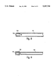
- FIG. 8 is a side elevational view in cross-section of a first embodiment wherein a disposable sheath in accordance with this invention is utilized as an end sleeve or cap in conjunction with tubing.
- FIG. 9 is a side elevational view in cross-section of a second embodiment wherein a sheath in accordance with this invention is utilized as an end sleeve or cap.
- FIG. 1 illustrates a disposable sheath 10 having elongated, tubular sidewalls 12, an open proximal end 14, and a closed or sealed distal end 16.
- End 16 comprises a substantially flat, optically transparent viewing window 18 formed continuously integral with sidewalls 12.
- optically transparent means capable of transmitting visible light so that a body can be clearly seen therethrough with little or no distortion.
- formed continuously integral with refers to two sections of a single element that flow substantially smoothly and continuously into one another along every interface without any discontinuous seam or edge such as that created by bonding one element to another using adhesives, thermal bonding or other techniques.
- the diameter of sheath 10 may range from about 0.5-40 mm. preferably from about 3-20 mm. Smaller diameter sheaths may be selected to accommodate smaller diameter medical devices to achieve a relatively close-fitting relationship.
- the thickness of sidewalls 12 and end 16 should be less than 0.015 inches. For some applications, it is desirable that the sidewall thickness be less than 0.010 inches, or even less than 0.005 inches. And, for some applications, a sidewall thickness less than 0.003 inches is preferred.
- sidewalls 12 are preferably linear and of substantially uniform diameter (i.e. a cylindrical configuration); for other applications, it may be desirable to have a somewhat larger diameter proximal end with sidewalls 12 smoothly tapering to a smaller diameter distal end (i.e. a frustoconical configuration).
- the length of sheath 10 will vary in accordance with the length of the medical instrument to be covered and the remoteness of the body cavity to be viewed, but sheath lengths ranging from about one-quarter inch to several feet are within the scope of this invention.
- the ratio of the diameter of the sheath to its length may range from about 1:1 to 1:100. Only the method of this invention makes possible the manufacture of very thin-walled (less than about 0.010 inches) integrally formed sheaths of very small diameters and relatively long lengths.
- end 16 of sheath 10 comprises a substantially flat, optically transparent viewing window 18 formed continuously integral with sidewalls 12.
- window 18 is very thin, typically having a thickness less than 0.015 inches. Even more important than the thickness of the window is the thickness of the sidewalls 12 because it is the thickness of the sidewalls that limits the overall diameter of the covered endoscope unit.
- the bond itself adds undesirable thickness to the diameter of the unit at the bonding point thereby limiting the utility of the entire instrument.
- the present invention facilitates minimizing the overall diameter of a covered endoscope unit by combining very thin sheath sidewalls with an integral window that requires no bonding.
- Sheath 10 of FIG. 1 is designed as a protective covering for an end-view endoscope or similar optical medical instrument.
- the plane of window 18 is substantially normal to the axis of sheath 10.
- FIG. 2 shows a side elevational view in cross-section along the line 2--2 of the sheath of FIG. 1 with an end-view endoscope 22, having a lens and/or light source 24 at the distal end thereof, shown in dotted outline inside sheath 10.
- Lens 24 of endoscope 22 is normal to the axis of the instrument and is positioned in close proximity to and in axial alignment with viewing window 18.
- FIG. 3 illustrates an alternative embodiment of this invention.
- sheath 30 has elongated tubular sidewalls 32, an open proximal end 34, and an angled or sloping closed distal end 36.
- End 36 comprises a substantially flat, optically clear viewing window 38 formed continuously integral with sidewalls 32.
- Sheath 30 of FIG. 3 is designed as a protective covering for an endoscope or similar optical medical instrument 42 having a slanted lens 44, as seen in FIG. 4. Similar to the embodiment shown in FIG. 2, the angled or sloping end 36 of sheath 30 facilitates positioning lens 44 of endoscope 42 adjacent to and in alignment with viewing window 38.
- End 36 of sheath 30 can be made sloping at virtually any angle required to accommodate the geometry of the lens of the medical instrument.
- sheaths having other distal end geometries, e.g. curved or parabolic, can also be prepared in accordance with this invention to correspond with similarly shaped endoscope lenses.
- FIG. 5 illustrates one embodiment of the method for preparing the protective sheaths of this invention.
- a sheet or film 50 of an optically transparent polymeric material is heated to a point where its viscosity is substantially reduced thus rendering it malleable.
- a male forming tool or mandrel 60 having a proximal end 62, a distal end 64, and sidewalls 66, is thrust into heated film 50 causing it to stretch and conform to the geometry of the mandrel thereby forming a closed end sleeve 52 having sidewalls 54, a flange or collar 55 at its proximal end, and a distal end 56.
- FIG. 5 illustrates one embodiment of the method for preparing the protective sheaths of this invention.
- distal end 64 of mandrel 60 comprises a substantially flat face or surface 68 that is substantially normal to the axis of mandrel 60.
- the distal end 56 of sleeve 52 is formed having a substantially flat, optically transparent window 58 continuously integral with sidewalls 54 and substantially normal to the axis of sleeve 52 (i.e. a sheath similar to that of FIG. 1).
- mandrel 60 at a suitable location along its length, may include a collar mold (not shown) of a generally bell-like shape. The effect of the collar mold is to cause flange 55 of sleeve 52 to conform to the shape of the collar mold.
- Such a molded flange section is designed to protect portions of the instruments outside the body from contamination.
- sheaths having a wide variety of shapes and sizes can be formed using the method of this invention.
- a mandrel having a slanted or angled face could be used to produce sheaths similar to that of FIG. 3.
- a mandrel with a substantially flat face along sidewalls 66 proximate to distal end 64 could be used to produce sheaths having optically transparent windows along their sidewalls to accommodate side-view endoscopes.
- a mandrel with a curved or parabolic distal end could be used to produce sheaths having comparable geometry.
- the forming process may also include integrally forming a molded collar having a diameter or cross-section larger than the rest of the sleeve at the open, proximal end of the sheath.
- a collar can be useful in covering the portion of the medical instrument located outside but adjacent to the body or in attaching a clamp to hold the sheath on to the scope.
- conventional plastic processing techniques such as thermoforming or injection molding, can also be used.
- the mandrel can be made with flat sidewalls to produce sheaths having various polyhedral cross-sectional configurations, e.g. triangular (3 flat sides) or rectangular (4 flat sides).
- the mandrel can be made in a frustoconical configuration to produce tubular sheaths with a smooth inward taper from the proximal to the distal end.
- Still another variation of this invention is to use a mandrel having a hollow end or hollow core.
- a hollow end forming tool would allow air to enter the interior of the sheath as the tool is withdrawn to prevent collapse of the sheath.
- a hollow core or internal channel in the mandrel could be used to supply air or another fluid (gas or liquid) to blow the formed sheath off of the tool.
- a double-walled cavity or channel inside the mandrel can be used, where desirable, to circulate a heat transfer fluid inside the mandrel for selectively heating or cooling the mandrel at various stages of the process of this invention. Other well known methods may also be used for selectively heating or cooling the mandrel.
- the sheath sidewall 54 may have a ribbed, accordian-like structure.
- this configuration enhances the flexibility of the sheath and facilitates installation of the combined unit into the body and articulation of the endoscope once in position.
- Such an accordian-like structure is readily achieved by axially compressing or sandwiching all or a selected portion of the formed sheath.
- sheaths with multi-layer sidewalls can be prepared by the methods described herein.
- Such multi-layer sidewalls can be utilized to provide enhanced reliability or durability, or, by using different materials for the different layers, to custom-tailor the properties of the sheath to a particular requirement.
- Such multi-layer sidewalls, and multi-layer molded collar sections if desired, can be formed by thrusting the mandrel 60 into a first heated film and, without removing the first-formed sheath, subsequently thrusting the sheathed mandrel into a second, third, etc. heated film to form second, third, etc. layers.
- a thin-walled thermoplastic or heat-shrinkable tube may be placed on the forming mandrel prior to thrusting the mandrel into a first heated film to form a two-layer sidewall of enhanced durability.
- FIG. 6 illustrates still another embodiment of this invention in which the window end 76 of sheath 70 is flared outward such that the outer diameter of the window 78 is slightly larger than the diameter of the rest of the sheath.
- the outer diameter of window 78 may be about 0.001-0.015 inches greater than the outer diameter of sidewall section 72.
- Flared window sheaths in accordance with this embodiment of the invention can be prepared similar to the methods described above in connection with FIGS. 2, 4 and 5, except that the mandrel or forming tool 82 will have a collapsible core or split ring construction at its distal end 84 to facilitate withdrawing the tool from the flared window sheath.
- FIG. 7 shows a sheath prepared in accordance with this invention formed over a relatively rigid, apertured plastic disc 90.
- Disc 90 comprises one or a plurality of disc apertures 91, 92 and 93, sized and shaped so as to mate with one or more working channels or elements of the endoscope intended to be covered by sheath 97.
- Disc 90 also comprises a window aperture 95 sized and shaped to mate with the viewing lens of the endoscope and to position that lens in alignment with the viewing window at the distal end of sheath 97.
- Disc 90 provides alignment of and stability to the various elements of the medical instrument being covered by sheath 97, for example by providing a rigid body for attaching the tubes projecting from the distal end of an endoscope.
- disc apertures 91 and 93 can communicate with working channels in the endoscope (not shown) while aperture disc 92 accommodates a fiber optic light coming through the endoscope.
- holes may be cut in the portion of sheath 97 adjacent the various disc apertures to accommodate tubes or working channels intended to extend beyond the distal end of sheath 97.
- Disc 90 can be prepared in virtually any desired size and shape through conventional injection molding or die cutting techniques. Disc 90 can be prepared such that apertures 91, 92, 93 and 95 are formed simultaneously with the disc or, alternatively, the apertures can be cut or punched from a preformed disc. Sheath 97, having thin sidewalls and a thin, optically transparent window in accordance with this invention, can be formed over a prefabricated disc 90 that has been placed at the end of the forming mandrel. Tubing or other components can be attached to the disc either before or after sheath formation.
- a variety of orientable and non-orientable elastoplastic polymeric materials can be used as the optically transparent starting film for producing the sheaths of this invention.
- Preferred starting materials include thin films of clear thermoplastics including thermoplastic polyesters such as PET, and PETG (a glycol-modified polyethylene terephthalate), PVC, acrylic and polycarbonate. These polymers provide an optimum combination of properties for producing long, small-diameter, thin-walled sheaths of high strength, flexible yet substantially inelastic sidewalls, and flexible, inelastic, optically transparent windows.
- a film of optically clear polymer instead of starting with a film of optically clear polymer, it may be desirable to choose a pigmented or tinted or coated polymeric film, for example a film coated with an anti-reflective coating.
- the resulting sheaths would have windows capable of filtering specific wavelengths of light.
- the protective sheaths of this invention may be desirable to utilize the protective sheaths of this invention as caps or end sleeves attached to longer pieces of hollow tubing as illustrated in FIGS. 8 and 9.
- the components can be joined using various common techniques, for example solvent bonding, adhesive bonding, heat bonding, ultrasonic welding, etc.
- solvent bonding for example solvent bonding, adhesive bonding, heat bonding, ultrasonic welding, etc.
- the sidewalls of the Siverstein et al. end caps are thick and the viewing windows are separately bonded to those sidewalls thereby further increasing the overall diameter of the end cap-sleeve combination.
- the protective sheaths of this invention are used as end sleeves, the thin side wall and integral window construction is preserved.
- the end sleeves of this invention can be advantageously used in place of the end caps described in the Silverstein et al. patent as well as other prior art end caps.
- a sheath 102 is prepared in accordance with this invention such that sheath 102 has an outer diameter approximately equal to or less than the inner diameter of elongated tubing 110 so that sheath 102 fits concentrically inside tubing 110.
- Outer sidewall 104 of sheath 102 is bonded by appropriate means to one end of the inner sidewall 112 of tubing 110 to form the complete protective sheath apparatus.
- a sheath 122 is prepared in accordance with this invention such that sheath 122 has an inner diameter approximately equal to or greater than the outer diameter of elongated tubing 130 so that sheath 122 fits concentrically over one end of tubing 130.
- Inner sidewall 124 of sheath 122 is bonded by appropriate means to the outer sidewall 132 of tubing 130 to form the complete protective sheath apparatus.
- a tube or series of tubes may be placed over or inside the forming tool and the window, as described previously, can be formed integrally over the tube, eliminating a secondary bonding step. This may be desirable for example when a very thin lens and a thick or stiff sidewall is wanted.
- Other types of reinforcement may be used, for example the sleeve could be formed over a spring or reinforcing wires or other shaped products.
- an image-enhancing or coupling fluid for example water or glycerine.
- an image-enhancing or coupling fluid for example water or glycerine.
- endoscopes that have working channels for sampling fluids, flushing, drainage etc. It is possible to thermally seal these tubes to the transparent lens by carefully positioning the tubes so that the ends of the tubes contact the soft hot film and fuse to the film during forming, or, alternatively, they can be attached later.
- the protective sheaths of this invention can also be used for other purposes beyond a sterile cover.
- a sterile cover For example, in arthroscopic surgery such as knee surgery high speed sharp cutters are used to shave away bones. In order to get the best view, these scopes are placed very close to the cutting area. This often results in accidental damage to the optics of the scope. This often occurs in teaching hospitals where student doctors practice these surgical techniques.
- Use of a protective sleeve in accordance with this invention can reduce the damage to these scopes, saving thousands of dollars in repair costs for a single scope.
Abstract
Description
Claims (63)
Priority Applications (2)
| Application Number | Priority Date | Filing Date | Title |
|---|---|---|---|
| US07/968,538 US5337734A (en) | 1992-10-29 | 1992-10-29 | Disposable sheath with optically transparent window formed continuously integral therewith |
| US08/225,172 US5443781A (en) | 1992-10-29 | 1994-04-08 | Method of preparing disposable sheath with optically transparent windows formed continuously integral therewith |
Applications Claiming Priority (1)
| Application Number | Priority Date | Filing Date | Title |
|---|---|---|---|
| US07/968,538 US5337734A (en) | 1992-10-29 | 1992-10-29 | Disposable sheath with optically transparent window formed continuously integral therewith |
Related Child Applications (1)
| Application Number | Title | Priority Date | Filing Date |
|---|---|---|---|
| US08/225,172 Division US5443781A (en) | 1992-10-29 | 1994-04-08 | Method of preparing disposable sheath with optically transparent windows formed continuously integral therewith |
Publications (1)
| Publication Number | Publication Date |
|---|---|
| US5337734A true US5337734A (en) | 1994-08-16 |
Family
ID=25514393
Family Applications (2)
| Application Number | Title | Priority Date | Filing Date |
|---|---|---|---|
| US07/968,538 Expired - Lifetime US5337734A (en) | 1992-10-29 | 1992-10-29 | Disposable sheath with optically transparent window formed continuously integral therewith |
| US08/225,172 Expired - Lifetime US5443781A (en) | 1992-10-29 | 1994-04-08 | Method of preparing disposable sheath with optically transparent windows formed continuously integral therewith |
Family Applications After (1)
| Application Number | Title | Priority Date | Filing Date |
|---|---|---|---|
| US08/225,172 Expired - Lifetime US5443781A (en) | 1992-10-29 | 1994-04-08 | Method of preparing disposable sheath with optically transparent windows formed continuously integral therewith |
Country Status (1)
| Country | Link |
|---|---|
| US (2) | US5337734A (en) |
Cited By (101)
| Publication number | Priority date | Publication date | Assignee | Title |
|---|---|---|---|---|
| NL1001251C2 (en) * | 1995-09-12 | 1997-03-13 | Int Medical Products B V | Rigid endoscope with disposable outer sleeve e.g. for medical and veterinary use |
| US5695454A (en) * | 1994-06-30 | 1997-12-09 | Mourkidou; Sotiria | Cover for a laryngoscope |
| US5807107A (en) * | 1995-10-20 | 1998-09-15 | Barrier Supply | Dental infection control system |
| WO1998041151A1 (en) * | 1997-03-17 | 1998-09-24 | Polartechnics Limited | Sheathed probes for tissue type recognition |
| GB2336540A (en) * | 1998-04-21 | 1999-10-27 | Alan James Purveur | Flexible endoscope cover |
| US5980450A (en) * | 1997-05-07 | 1999-11-09 | Pinotage, Llc | Coupling device for use in an imaging system |
| US6129662A (en) * | 1996-06-03 | 2000-10-10 | Cogent Light Technologies, Inc. | Surgical tool with surgical field illuminator |
| WO2000042900A3 (en) * | 1999-01-21 | 2000-11-02 | Vision Sciences Inc | Forming thin-walled elastic components from an elastomeric material |
| WO2000069332A1 (en) * | 1999-05-18 | 2000-11-23 | Scimed Life Systems, Inc. | Optical biopsy system |
| WO2000074556A3 (en) * | 1999-06-09 | 2001-07-12 | Medispectra Inc | An optical probe accessory device for use in in vivo diagnostic procedures |
| EP1143275A2 (en) * | 2000-04-07 | 2001-10-10 | Panduit Corporation | Fiber optic sleeve with tapered corner-wall sections |
| US20010041843A1 (en) * | 1999-02-02 | 2001-11-15 | Mark Modell | Spectral volume microprobe arrays |
| US6346073B1 (en) | 1997-05-07 | 2002-02-12 | Pinotage, Llc | Imaging system and components thereof |
| US6346074B1 (en) * | 1993-02-22 | 2002-02-12 | Heartport, Inc. | Devices for less invasive intracardiac interventions |
| US6385484B2 (en) | 1998-12-23 | 2002-05-07 | Medispectra, Inc. | Spectroscopic system employing a plurality of data types |
| US6411835B1 (en) | 1997-01-13 | 2002-06-25 | Medispectra, Inc. | Spectral volume microprobe arrays |
| US6436108B1 (en) * | 2000-04-19 | 2002-08-20 | Ensurg, Inc. | Movable ligating band dispenser |
| US6464383B1 (en) | 1998-12-09 | 2002-10-15 | Steris Inc. | Fiber optic ceiling supported surgical task light system with optical commutator and manual zoom lens |
| US6478730B1 (en) | 1998-09-09 | 2002-11-12 | Visionscope, Inc. | Zoom laparoscope |
| US20030008083A1 (en) * | 1997-10-10 | 2003-01-09 | Harhen E. Paul | Methods for forming complex-shaped components in a heated polymeric film |
| US6530881B1 (en) * | 1999-01-21 | 2003-03-11 | Vision Sciences, Inc. | Sheath apparatus for endoscopes and methods for forming same |
| US6549794B1 (en) | 1999-09-24 | 2003-04-15 | Cytometrics, Llc | Single use disposable protective cap |
| US6554797B1 (en) | 1999-02-19 | 2003-04-29 | Alsius Corporation | Method and system for patient temperature management and central venous access |
| US6585692B1 (en) | 1999-02-19 | 2003-07-01 | Alsius Corporation | Method and system for patient temperature management and central venous access |
| US20030125721A1 (en) * | 1998-03-31 | 2003-07-03 | Yon Steven A. | Method and device for performing cooling or cryo-therapies, for, e.g., angioplasty with reduced restenosis or pulmonary vein cell necrosis to inhibit atrial fibrillation employing tissue protection |
| US6602276B2 (en) | 1998-03-31 | 2003-08-05 | Innercool Therapies, Inc. | Method and device for performing cooling- or cryo-therapies for, e.g., angioplasty with reduced restenosis or pulmonary vein cell necrosis to inhibit atrial fibrillation |
| EP1335662A1 (en) * | 2000-10-27 | 2003-08-20 | Pulmonx | Sheath and method for reconfiguring lung viewing scope |
| US6632235B2 (en) | 2001-04-19 | 2003-10-14 | Synthes (U.S.A.) | Inflatable device and method for reducing fractures in bone and in treating the spine |
| WO2003051183A3 (en) * | 2001-12-18 | 2003-12-18 | Advanced Cardiovascular System | Sheath for guiding imaging instruments |
| US6685732B2 (en) | 1998-03-31 | 2004-02-03 | Innercool Therapies, Inc. | Method and device for performing cooling- or cryo-therapies for, e.g., angioplasty with reduced restenosis or pulmonary vein cell necrosis to inhibit atrial fibrillation employing microporous balloon |
| US20040034287A1 (en) * | 2002-05-16 | 2004-02-19 | Scott Laboratories, Inc. | System and method for permitting sterile operation of a sedation and analgesia system |
| US20040059253A1 (en) * | 2002-01-04 | 2004-03-25 | Stephen Martone | Endoscope sheath assemblies having an attached biopsy sampling device |
| US20040097957A1 (en) * | 2002-10-18 | 2004-05-20 | Marc Jaker | Medical device, drug delivery and lab sampling system utilizing an inverting sheath technology |
| US6761684B1 (en) * | 2000-08-10 | 2004-07-13 | Linvatec Corporation | Endoscope tip protection system |
| US6768918B2 (en) | 2002-07-10 | 2004-07-27 | Medispectra, Inc. | Fluorescent fiberoptic probe for tissue health discrimination and method of use thereof |
| US6818903B2 (en) | 2002-07-09 | 2004-11-16 | Medispectra, Inc. | Method and apparatus for identifying spectral artifacts |
| US6826422B1 (en) | 1997-01-13 | 2004-11-30 | Medispectra, Inc. | Spectral volume microprobe arrays |
| US6839661B2 (en) | 2000-12-15 | 2005-01-04 | Medispectra, Inc. | System for normalizing spectra |
| US6902935B2 (en) | 1999-12-15 | 2005-06-07 | Medispectra, Inc. | Methods of monitoring effects of chemical agents on a sample |
| WO2005058147A1 (en) * | 2003-12-18 | 2005-06-30 | Patents Exploitation Company B.V. | Flexible protective sheath for an endoscope |
| US20050171470A1 (en) * | 2004-01-29 | 2005-08-04 | Cannuflow Incorporated | Atraumatic arthroscopic instrument sheath |
| US20050192532A1 (en) * | 2004-01-29 | 2005-09-01 | Kucklick Theodore R. | Atraumatic arthroscopic instrument sheath |
| US20050203342A1 (en) * | 2004-01-29 | 2005-09-15 | Cannuflow Incorporated | Atraumatic arthroscopic instrument sheath |
| US20050234298A1 (en) * | 2004-01-29 | 2005-10-20 | Cannuflow Incorporated | Atraumatic arthroscopic instrument sheath |
| US20050256377A1 (en) * | 2004-05-12 | 2005-11-17 | Deppmeier Thomas R | Endoscope and related system |
| US20050267330A1 (en) * | 2004-05-12 | 2005-12-01 | Deppmeier Thomas R | Endoscope and related system |
| US20050283048A1 (en) * | 2001-10-19 | 2005-12-22 | Visionscope, Llc | Portable imaging system employing a miniature endoscope |
| US20060149127A1 (en) * | 2004-12-30 | 2006-07-06 | Seddiqui Fred R | Disposable multi-lumen catheter with reusable stylet |
| US7103401B2 (en) | 2002-07-10 | 2006-09-05 | Medispectra, Inc. | Colonic polyp discrimination by tissue fluorescence and fiberoptic probe |
| US20070010823A1 (en) * | 2005-07-11 | 2007-01-11 | Cannuflow, Inc. | Arthroscopic shaver system |
| US20070015989A1 (en) * | 2005-07-01 | 2007-01-18 | Avantis Medical Systems, Inc. | Endoscope Image Recognition System and Method |
| US20070167681A1 (en) * | 2001-10-19 | 2007-07-19 | Gill Thomas J | Portable imaging system employing a miniature endoscope |
| US20070249899A1 (en) * | 2006-04-05 | 2007-10-25 | Alexander Seifert | Deflectable tip videoarthroscope |
| US20070279486A1 (en) * | 2006-05-19 | 2007-12-06 | Avantis Medical Systems, Inc. | Device and method for reducing effects of video artifacts |
| US20080033450A1 (en) * | 2006-08-04 | 2008-02-07 | Lex Bayer | Surgical Port With Embedded Imaging Device |
| US20080064925A1 (en) * | 2001-10-19 | 2008-03-13 | Gill Thomas J | Portable imaging system employing a miniature endoscope |
| US20080253686A1 (en) * | 2007-04-10 | 2008-10-16 | Avantis Medical Systems, Inc. | Method and Device for Examining or Imaging an Interior Surface of a Cavity |
| US20080257484A1 (en) * | 2007-03-07 | 2008-10-23 | Tetsuya Fujikura | Method of working end portion of tube for medical instrument |
| EP1989991A1 (en) * | 2007-05-07 | 2008-11-12 | Endoclarix S.r.L. | Protective device for endoscopic apparatus |
| US20090143648A1 (en) * | 2007-11-30 | 2009-06-04 | Tyco Healthcare Group Lp | Endoscope system for gastrostomy catheter placement |
| US20100063359A1 (en) * | 2007-04-11 | 2010-03-11 | Tyco Healthcare Group Lp | Endoscopic/laparoscopic introducer sleeve |
| US20100175496A1 (en) * | 2009-01-14 | 2010-07-15 | Samsung Electronics Co., Ltd. | Robot |
| US20110017213A1 (en) * | 2009-07-24 | 2011-01-27 | Vadney Mark V | Surgical and Anesthesia Conduit Cover Kit and Method |
| US7942814B2 (en) | 2001-10-19 | 2011-05-17 | Visionscope Technologies Llc | Miniature endoscope with imaging fiber system |
| US8043283B2 (en) | 1998-03-31 | 2011-10-25 | Innercool Therapies, Inc. | Method and device for performing cooling- or cryo-therapies for, e.g., angioplasty with reduced restenosis or pulmonary vein cell necrosis to inhibit atrial fibrillation |
| US20110282152A1 (en) * | 2010-05-12 | 2011-11-17 | Q Park Medical Limited | Sheath for protecting endoscope probe |
| US8142352B2 (en) | 2006-04-03 | 2012-03-27 | Welch Allyn, Inc. | Vaginal speculum assembly having portable illuminator |
| US8157728B2 (en) | 2005-04-01 | 2012-04-17 | Welch Allyn, Inc. | Vaginal speculum |
| US8182422B2 (en) | 2005-12-13 | 2012-05-22 | Avantis Medical Systems, Inc. | Endoscope having detachable imaging device and method of using |
| US8235887B2 (en) | 2006-01-23 | 2012-08-07 | Avantis Medical Systems, Inc. | Endoscope assembly with retroscope |
| US8289381B2 (en) | 2005-01-05 | 2012-10-16 | Avantis Medical Systems, Inc. | Endoscope with an imaging catheter assembly and method of configuring an endoscope |
| US8287446B2 (en) | 2006-04-18 | 2012-10-16 | Avantis Medical Systems, Inc. | Vibratory device, endoscope having such a device, method for configuring an endoscope, and method of reducing looping of an endoscope |
| US20120281218A1 (en) * | 2005-01-24 | 2012-11-08 | The Board Of Trustees Of The Leland Stanford Junior University | Optical analysis system and approach therefor |
| US8317689B1 (en) | 1999-09-13 | 2012-11-27 | Visionscope Technologies Llc | Miniature endoscope system |
| US8388523B2 (en) | 2005-04-01 | 2013-03-05 | Welch Allyn, Inc. | Medical diagnostic instrument having portable illuminator |
| US8797392B2 (en) | 2005-01-05 | 2014-08-05 | Avantis Medical Sytems, Inc. | Endoscope assembly with a polarizing filter |
| US8872906B2 (en) | 2005-01-05 | 2014-10-28 | Avantis Medical Systems, Inc. | Endoscope assembly with a polarizing filter |
| US20140318551A1 (en) * | 2013-04-29 | 2014-10-30 | Contour Fabricators, Inc. | Craniotomy Drape and Method of Simultaneously Draping a Sterile Barrier Over a Patient and Navigation Tracker |
| US8905921B2 (en) | 2011-02-16 | 2014-12-09 | The General Hospital Corporation | Optical coupler for an endoscope |
| US20150069728A1 (en) * | 2010-09-24 | 2015-03-12 | John Russell Seitz, III | Multifunctional enclosure system for medical probes and method of use |
| USD731652S1 (en) | 2014-02-19 | 2015-06-09 | Tidi Products, Llc | Dental curing light sleeve |
| US20150201902A1 (en) * | 2012-07-11 | 2015-07-23 | The University Of Connecticut | Dual-modality endoscope, method of manufacture, and use thereof |
| WO2015120348A1 (en) | 2014-02-06 | 2015-08-13 | Dentsply International Inc. | Inspection of dental roots and the endodontic cavity space therein |
| US9433468B2 (en) | 2013-10-04 | 2016-09-06 | Tidi Products, Llc | Sheath for a medical or dental instrument |
| US9459442B2 (en) | 2014-09-23 | 2016-10-04 | Scott Miller | Optical coupler for optical imaging visualization device |
| US9532706B2 (en) | 2014-08-07 | 2017-01-03 | Welch Allyn, Inc. | Vaginal speculum with illuminator |
| ITUB20155512A1 (en) * | 2015-11-12 | 2017-05-12 | Cover S R L | Method for producing a protection device for medical instruments of the optical type and a protection device thus obtained |
| CN106923778A (en) * | 2017-04-25 | 2017-07-07 | 湖北迪奥医疗科技有限公司 | A kind of disposable hard endoscope casing tube camera lens and alignment lenses method |
| EP3210521A1 (en) * | 2016-02-24 | 2017-08-30 | Richard Wolf GmbH | Endoscopic shaft instrument |
| WO2019152601A1 (en) * | 2018-01-31 | 2019-08-08 | UVision360, Inc. | Flexible imaging window |
| US10548467B2 (en) | 2015-06-02 | 2020-02-04 | GI Scientific, LLC | Conductive optical element |
| US10709317B2 (en) | 2018-10-04 | 2020-07-14 | PraesidioDyne, LLC | Clamp assembly for disposable endoscopic sheaths |
| EP3689220A2 (en) | 2019-01-31 | 2020-08-05 | Canon U.S.A. Inc. | Window assembly for endoscopic probe |
| US10842352B2 (en) | 2016-04-11 | 2020-11-24 | Canon U.S.A., Inc. | Endoscope sheath with integral imaging window |
| US10856724B2 (en) | 2015-07-21 | 2020-12-08 | GI Scientific, LLC | Endoscope accessory with angularly adjustable exit portal |
| US10895692B2 (en) | 2017-06-01 | 2021-01-19 | Canon U.S.A., Inc. | Fiber optic rotary joints and methods of using and manufacturing same |
| US10996402B2 (en) | 2016-03-24 | 2021-05-04 | Canon U.S.A., Inc. | Multi-channel optical fiber rotary junction |
| CN112888358A (en) * | 2018-10-04 | 2021-06-01 | 强大的安全有限责任公司 | Endoscope sheath holding assembly and dip-molded disposable endoscope sheath |
| EP4066725A1 (en) * | 2021-03-30 | 2022-10-05 | Bidoia Medica Sas Di Bidoia Gianfranco | Protection device for an endoscopic apparatus |
| EP4223204A1 (en) * | 2022-02-02 | 2023-08-09 | Canon U.S.A. Inc. | Antitwist mechanism for robotic endoscope camera |
| EP4189461A4 (en) * | 2020-07-27 | 2024-01-31 | 270 Surgical Ltd | Mitigating smudging of an endoscope window elements during a medical procedure |
Families Citing this family (14)
| Publication number | Priority date | Publication date | Assignee | Title |
|---|---|---|---|---|
| US6096065A (en) * | 1997-09-29 | 2000-08-01 | Boston Scientific Corporation | Sheath for tissue spectroscopy |
| WO2002013681A1 (en) * | 2000-08-10 | 2002-02-21 | Vision Sciences, Inc. | Apparatus and method for forming complex-shaped components in a heated polymeric film |
| ES2285616T3 (en) * | 2000-12-15 | 2007-11-16 | Covidien Ag | ELECTROCHIRURGICAL ELECTRODE ENVELOPE. |
| US6891984B2 (en) * | 2002-07-25 | 2005-05-10 | Lightlab Imaging, Llc | Scanning miniature optical probes with optical distortion correction and rotational control |
| US20050177025A1 (en) * | 2004-01-28 | 2005-08-11 | Marc Jaker | Prophylactic polymer probe cover |
| US20050261582A1 (en) * | 2004-05-18 | 2005-11-24 | Matthew Becker | Intracorporeal probe with disposable probe body |
| GB0718093D0 (en) * | 2007-09-17 | 2007-10-24 | Park Medical Ltd Q | Sheath assembly |
| US9345853B2 (en) | 2010-12-10 | 2016-05-24 | Teknor Apex Company | Tube assembly and method for making the assembly |
| CN112998664A (en) | 2015-04-16 | 2021-06-22 | Gentuity有限责任公司 | Low-light level probe for neurology |
| JP6981967B2 (en) | 2015-08-31 | 2021-12-17 | ジェンテュイティ・リミテッド・ライアビリティ・カンパニーGentuity, LLC | Imaging system including imaging probe and delivery device |
| PE20201452A1 (en) * | 2017-08-01 | 2020-12-15 | Seed Co Ltd | ENDOSCOPE CAP |
| IT201700106689A1 (en) * | 2017-09-25 | 2019-03-25 | Bidoia S A S Di Gianfranco Bidoia E C | PROTECTION DEVICE FOR ENDOSCOPIC EQUIPMENT |
| JP7160935B2 (en) | 2017-11-28 | 2022-10-25 | ジェンテュイティ・リミテッド・ライアビリティ・カンパニー | Imaging system |
| WO2023196415A1 (en) * | 2022-04-08 | 2023-10-12 | Trustees Of Tufts College | Probe tip for in vivo multi-photon measurements |
Citations (22)
| Publication number | Priority date | Publication date | Assignee | Title |
|---|---|---|---|---|
| US3162190A (en) * | 1962-10-31 | 1964-12-22 | Gizzo Giovanni Del | Diagnostic and exploratory instrument |
| US3794091A (en) * | 1971-10-07 | 1974-02-26 | Med General Inc | Sterile sheath for surgical illuminator |
| US3809072A (en) * | 1971-10-07 | 1974-05-07 | Med General Inc | Sterile sheath apparatus for fiber optic illuminator with compatible lens |
| US4201199A (en) * | 1978-01-13 | 1980-05-06 | Smith Donald C | Endoscope attachment to a viewing instrument for insertion into the uterine cavity |
| US4470407A (en) * | 1982-03-11 | 1984-09-11 | Laserscope, Inc. | Endoscopic device |
| US4576156A (en) * | 1978-04-17 | 1986-03-18 | Ortho Pharmaceutical Corporation | Prophylactic device and method |
| US4646722A (en) * | 1984-12-10 | 1987-03-03 | Opielab, Inc. | Protective endoscope sheath and method of installing same |
| US4684490A (en) * | 1983-11-28 | 1987-08-04 | Deseret Medical, Inc. | Process for preparation of polyurethane condoms |
| US4698791A (en) * | 1986-06-17 | 1987-10-06 | Exxon Production Research Company | Acoustic well logging method for improved amplitude data acquisition |
| US4741326A (en) * | 1986-10-01 | 1988-05-03 | Fujinon, Inc. | Endoscope disposable sheath |
| US4819620A (en) * | 1986-08-16 | 1989-04-11 | Ichiro Okutsu | Endoscope guide pipe |
| US4820349A (en) * | 1987-08-21 | 1989-04-11 | C. R. Bard, Inc. | Dilatation catheter with collapsible outer diameter |
| USRE32983E (en) * | 1983-07-05 | 1989-07-11 | E. I. Du Pont De Nemours And Company | Balloon and manufacture thereof |
| US4878485A (en) * | 1989-02-03 | 1989-11-07 | Adair Edwin Lloyd | Rigid video endoscope with heat sterilizable sheath |
| US4886049A (en) * | 1988-05-17 | 1989-12-12 | Darras Robert L | Medical instrument cover |
| US4907395A (en) * | 1988-05-13 | 1990-03-13 | Opielab, Inc. | Packaging system for disposable endoscope sheaths |
| US4957112A (en) * | 1987-11-20 | 1990-09-18 | Olympus Optical Co., Ltd. | Ultrasonic diagnostic apparatus |
| USRE33561E (en) * | 1983-07-05 | 1991-03-26 | E. I. Du Pont De Nemours And Company | Balloon and manufacture thereof |
| US5024852A (en) * | 1987-08-20 | 1991-06-18 | Hutchinson | Process for preparing a prophylactic device made of rupturable microcapsules and layers of elastomeric material |
| US5029574A (en) * | 1988-04-14 | 1991-07-09 | Okamoto Industries, Inc. | Endoscopic balloon with a protective film thereon |
| US5078483A (en) * | 1988-09-23 | 1992-01-07 | Renate Dunsch-Herzberg | Disposable tubular film cover for arthroscopy cameras and method for covering arthroscopy cameras by means of such a disposable cover |
| US5176152A (en) * | 1990-10-31 | 1993-01-05 | Family Health International | Method of providing convolutable areas on thermoplastic elastomeric films, and films and film products having such areas |
Family Cites Families (2)
| Publication number | Priority date | Publication date | Assignee | Title |
|---|---|---|---|---|
| US3698791A (en) * | 1971-04-19 | 1972-10-17 | Xerox Corp | Drape for operating microscope |
| US4069280A (en) * | 1972-10-20 | 1978-01-17 | Kidder Raymond W | Method of making plastic optical fibers |
-
1992
- 1992-10-29 US US07/968,538 patent/US5337734A/en not_active Expired - Lifetime
-
1994
- 1994-04-08 US US08/225,172 patent/US5443781A/en not_active Expired - Lifetime
Patent Citations (22)
| Publication number | Priority date | Publication date | Assignee | Title |
|---|---|---|---|---|
| US3162190A (en) * | 1962-10-31 | 1964-12-22 | Gizzo Giovanni Del | Diagnostic and exploratory instrument |
| US3794091A (en) * | 1971-10-07 | 1974-02-26 | Med General Inc | Sterile sheath for surgical illuminator |
| US3809072A (en) * | 1971-10-07 | 1974-05-07 | Med General Inc | Sterile sheath apparatus for fiber optic illuminator with compatible lens |
| US4201199A (en) * | 1978-01-13 | 1980-05-06 | Smith Donald C | Endoscope attachment to a viewing instrument for insertion into the uterine cavity |
| US4576156A (en) * | 1978-04-17 | 1986-03-18 | Ortho Pharmaceutical Corporation | Prophylactic device and method |
| US4470407A (en) * | 1982-03-11 | 1984-09-11 | Laserscope, Inc. | Endoscopic device |
| USRE32983E (en) * | 1983-07-05 | 1989-07-11 | E. I. Du Pont De Nemours And Company | Balloon and manufacture thereof |
| USRE33561E (en) * | 1983-07-05 | 1991-03-26 | E. I. Du Pont De Nemours And Company | Balloon and manufacture thereof |
| US4684490A (en) * | 1983-11-28 | 1987-08-04 | Deseret Medical, Inc. | Process for preparation of polyurethane condoms |
| US4646722A (en) * | 1984-12-10 | 1987-03-03 | Opielab, Inc. | Protective endoscope sheath and method of installing same |
| US4698791A (en) * | 1986-06-17 | 1987-10-06 | Exxon Production Research Company | Acoustic well logging method for improved amplitude data acquisition |
| US4819620A (en) * | 1986-08-16 | 1989-04-11 | Ichiro Okutsu | Endoscope guide pipe |
| US4741326A (en) * | 1986-10-01 | 1988-05-03 | Fujinon, Inc. | Endoscope disposable sheath |
| US5024852A (en) * | 1987-08-20 | 1991-06-18 | Hutchinson | Process for preparing a prophylactic device made of rupturable microcapsules and layers of elastomeric material |
| US4820349A (en) * | 1987-08-21 | 1989-04-11 | C. R. Bard, Inc. | Dilatation catheter with collapsible outer diameter |
| US4957112A (en) * | 1987-11-20 | 1990-09-18 | Olympus Optical Co., Ltd. | Ultrasonic diagnostic apparatus |
| US5029574A (en) * | 1988-04-14 | 1991-07-09 | Okamoto Industries, Inc. | Endoscopic balloon with a protective film thereon |
| US4907395A (en) * | 1988-05-13 | 1990-03-13 | Opielab, Inc. | Packaging system for disposable endoscope sheaths |
| US4886049A (en) * | 1988-05-17 | 1989-12-12 | Darras Robert L | Medical instrument cover |
| US5078483A (en) * | 1988-09-23 | 1992-01-07 | Renate Dunsch-Herzberg | Disposable tubular film cover for arthroscopy cameras and method for covering arthroscopy cameras by means of such a disposable cover |
| US4878485A (en) * | 1989-02-03 | 1989-11-07 | Adair Edwin Lloyd | Rigid video endoscope with heat sterilizable sheath |
| US5176152A (en) * | 1990-10-31 | 1993-01-05 | Family Health International | Method of providing convolutable areas on thermoplastic elastomeric films, and films and film products having such areas |
Cited By (180)
| Publication number | Priority date | Publication date | Assignee | Title |
|---|---|---|---|---|
| US20040117032A1 (en) * | 1993-02-22 | 2004-06-17 | Roth Alex T. | Devices for less-invasive intracardiac interventions |
| US6651672B2 (en) | 1993-02-22 | 2003-11-25 | Heartport, Inc. | Devices for less-invasive intracardiac interventions |
| US6346074B1 (en) * | 1993-02-22 | 2002-02-12 | Heartport, Inc. | Devices for less invasive intracardiac interventions |
| US5695454A (en) * | 1994-06-30 | 1997-12-09 | Mourkidou; Sotiria | Cover for a laryngoscope |
| NL1001251C2 (en) * | 1995-09-12 | 1997-03-13 | Int Medical Products B V | Rigid endoscope with disposable outer sleeve e.g. for medical and veterinary use |
| US5807107A (en) * | 1995-10-20 | 1998-09-15 | Barrier Supply | Dental infection control system |
| US6129662A (en) * | 1996-06-03 | 2000-10-10 | Cogent Light Technologies, Inc. | Surgical tool with surgical field illuminator |
| US6411835B1 (en) | 1997-01-13 | 2002-06-25 | Medispectra, Inc. | Spectral volume microprobe arrays |
| US6826422B1 (en) | 1997-01-13 | 2004-11-30 | Medispectra, Inc. | Spectral volume microprobe arrays |
| WO1998041151A1 (en) * | 1997-03-17 | 1998-09-24 | Polartechnics Limited | Sheathed probes for tissue type recognition |
| US5830146A (en) * | 1997-03-17 | 1998-11-03 | Polartechnics Limited | Sheathed probes for tissue type recognition |
| US5980450A (en) * | 1997-05-07 | 1999-11-09 | Pinotage, Llc | Coupling device for use in an imaging system |
| US6346073B1 (en) | 1997-05-07 | 2002-02-12 | Pinotage, Llc | Imaging system and components thereof |
| US7025923B2 (en) | 1997-10-10 | 2006-04-11 | Vision Sciences, Inc. | Methods for forming complex-shaped components in a heated polymeric film |
| US6579582B1 (en) | 1997-10-10 | 2003-06-17 | Vision Sciences Inc. | Apparatus and method for forming complex-shaped components in a heated polymeric film |
| US20030008083A1 (en) * | 1997-10-10 | 2003-01-09 | Harhen E. Paul | Methods for forming complex-shaped components in a heated polymeric film |
| US6685732B2 (en) | 1998-03-31 | 2004-02-03 | Innercool Therapies, Inc. | Method and device for performing cooling- or cryo-therapies for, e.g., angioplasty with reduced restenosis or pulmonary vein cell necrosis to inhibit atrial fibrillation employing microporous balloon |
| US8043283B2 (en) | 1998-03-31 | 2011-10-25 | Innercool Therapies, Inc. | Method and device for performing cooling- or cryo-therapies for, e.g., angioplasty with reduced restenosis or pulmonary vein cell necrosis to inhibit atrial fibrillation |
| US8157794B2 (en) | 1998-03-31 | 2012-04-17 | Innercool Therapies, Inc. | Method and device for performing cooling-or cryo-therapies for, e.g., angioplasty with reduced restenosis or pulmonary vein cell necrosis to inhibit atrial fibrillation |
| US6602276B2 (en) | 1998-03-31 | 2003-08-05 | Innercool Therapies, Inc. | Method and device for performing cooling- or cryo-therapies for, e.g., angioplasty with reduced restenosis or pulmonary vein cell necrosis to inhibit atrial fibrillation |
| US20030125721A1 (en) * | 1998-03-31 | 2003-07-03 | Yon Steven A. | Method and device for performing cooling or cryo-therapies, for, e.g., angioplasty with reduced restenosis or pulmonary vein cell necrosis to inhibit atrial fibrillation employing tissue protection |
| GB2336540A (en) * | 1998-04-21 | 1999-10-27 | Alan James Purveur | Flexible endoscope cover |
| US6478730B1 (en) | 1998-09-09 | 2002-11-12 | Visionscope, Inc. | Zoom laparoscope |
| US6464383B1 (en) | 1998-12-09 | 2002-10-15 | Steris Inc. | Fiber optic ceiling supported surgical task light system with optical commutator and manual zoom lens |
| US6411838B1 (en) | 1998-12-23 | 2002-06-25 | Medispectra, Inc. | Systems and methods for optical examination of samples |
| US6385484B2 (en) | 1998-12-23 | 2002-05-07 | Medispectra, Inc. | Spectroscopic system employing a plurality of data types |
| US6760613B2 (en) | 1998-12-23 | 2004-07-06 | Medispectra, Inc. | Substantially monostatic, substantially confocal optical systems for examination of samples |
| WO2000042900A3 (en) * | 1999-01-21 | 2000-11-02 | Vision Sciences Inc | Forming thin-walled elastic components from an elastomeric material |
| US6733440B2 (en) * | 1999-01-21 | 2004-05-11 | Vision Sciences, Inc. | Apparatus and method for forming thin-walled elastic components from an elastomeric material |
| US6530881B1 (en) * | 1999-01-21 | 2003-03-11 | Vision Sciences, Inc. | Sheath apparatus for endoscopes and methods for forming same |
| US6350231B1 (en) | 1999-01-21 | 2002-02-26 | Vision Sciences, Inc. | Apparatus and method for forming thin-walled elastic components from an elastomeric material |
| AU765296B2 (en) * | 1999-01-21 | 2003-09-11 | Vision Sciences, Inc. | Apparatus and method for forming thin-walled elastic components from an elastomeric material |
| US20010041843A1 (en) * | 1999-02-02 | 2001-11-15 | Mark Modell | Spectral volume microprobe arrays |
| US6585692B1 (en) | 1999-02-19 | 2003-07-01 | Alsius Corporation | Method and system for patient temperature management and central venous access |
| US6554797B1 (en) | 1999-02-19 | 2003-04-29 | Alsius Corporation | Method and system for patient temperature management and central venous access |
| US6942644B2 (en) | 1999-02-19 | 2005-09-13 | Alsius Corporation | Method and system for patient temperature management and central venous access |
| US20030195465A1 (en) * | 1999-02-19 | 2003-10-16 | Alsius Corp. | Method and system for patient temperature management and central venous access |
| WO2000069332A1 (en) * | 1999-05-18 | 2000-11-23 | Scimed Life Systems, Inc. | Optical biopsy system |
| WO2000074556A3 (en) * | 1999-06-09 | 2001-07-12 | Medispectra Inc | An optical probe accessory device for use in in vivo diagnostic procedures |
| US8317689B1 (en) | 1999-09-13 | 2012-11-27 | Visionscope Technologies Llc | Miniature endoscope system |
| US6549794B1 (en) | 1999-09-24 | 2003-04-15 | Cytometrics, Llc | Single use disposable protective cap |
| US6902935B2 (en) | 1999-12-15 | 2005-06-07 | Medispectra, Inc. | Methods of monitoring effects of chemical agents on a sample |
| EP1143275A3 (en) * | 2000-04-07 | 2004-05-19 | Panduit Corporation | Fiber optic sleeve with tapered corner-wall sections |
| EP1143275A2 (en) * | 2000-04-07 | 2001-10-10 | Panduit Corporation | Fiber optic sleeve with tapered corner-wall sections |
| US6436108B1 (en) * | 2000-04-19 | 2002-08-20 | Ensurg, Inc. | Movable ligating band dispenser |
| JP2004510464A (en) * | 2000-07-07 | 2004-04-08 | ビジョン サイエンシーズ, インコーポレイテッド | Endoscope sheath and method of forming the sheath |
| US6761684B1 (en) * | 2000-08-10 | 2004-07-13 | Linvatec Corporation | Endoscope tip protection system |
| EP1335662A4 (en) * | 2000-10-27 | 2007-05-30 | Pulmonx | Sheath and method for reconfiguring lung viewing scope |
| EP1335662A1 (en) * | 2000-10-27 | 2003-08-20 | Pulmonx | Sheath and method for reconfiguring lung viewing scope |
| US6839661B2 (en) | 2000-12-15 | 2005-01-04 | Medispectra, Inc. | System for normalizing spectra |
| US6632235B2 (en) | 2001-04-19 | 2003-10-14 | Synthes (U.S.A.) | Inflatable device and method for reducing fractures in bone and in treating the spine |
| US7666205B2 (en) | 2001-04-19 | 2010-02-23 | Synthes Usa, Llc | Inflatable device and method for reducing fractures in bone and in treating the spine |
| US11484189B2 (en) | 2001-10-19 | 2022-11-01 | Visionscope Technologies Llc | Portable imaging system employing a miniature endoscope |
| US8038602B2 (en) | 2001-10-19 | 2011-10-18 | Visionscope Llc | Portable imaging system employing a miniature endoscope |
| US7942814B2 (en) | 2001-10-19 | 2011-05-17 | Visionscope Technologies Llc | Miniature endoscope with imaging fiber system |
| US20080064925A1 (en) * | 2001-10-19 | 2008-03-13 | Gill Thomas J | Portable imaging system employing a miniature endoscope |
| US20070167681A1 (en) * | 2001-10-19 | 2007-07-19 | Gill Thomas J | Portable imaging system employing a miniature endoscope |
| US10595710B2 (en) | 2001-10-19 | 2020-03-24 | Visionscope Technologies Llc | Portable imaging system employing a miniature endoscope |
| US20050283048A1 (en) * | 2001-10-19 | 2005-12-22 | Visionscope, Llc | Portable imaging system employing a miniature endoscope |
| WO2003051183A3 (en) * | 2001-12-18 | 2003-12-18 | Advanced Cardiovascular System | Sheath for guiding imaging instruments |
| AU2003202865B2 (en) * | 2002-01-04 | 2008-03-13 | Medtronic Xomed, Inc | Endoscope sheath assemblies having an attached biopsy sampling device |
| US20040059253A1 (en) * | 2002-01-04 | 2004-03-25 | Stephen Martone | Endoscope sheath assemblies having an attached biopsy sampling device |
| US7081097B2 (en) * | 2002-01-04 | 2006-07-25 | Vision Sciences, Inc. | Endoscope sheath assemblies having an attached biopsy sampling device |
| US20040034287A1 (en) * | 2002-05-16 | 2004-02-19 | Scott Laboratories, Inc. | System and method for permitting sterile operation of a sedation and analgesia system |
| US6818903B2 (en) | 2002-07-09 | 2004-11-16 | Medispectra, Inc. | Method and apparatus for identifying spectral artifacts |
| US6768918B2 (en) | 2002-07-10 | 2004-07-27 | Medispectra, Inc. | Fluorescent fiberoptic probe for tissue health discrimination and method of use thereof |
| US7103401B2 (en) | 2002-07-10 | 2006-09-05 | Medispectra, Inc. | Colonic polyp discrimination by tissue fluorescence and fiberoptic probe |
| US8005527B2 (en) | 2002-07-10 | 2011-08-23 | Luma Imaging Corporation | Method of determining a condition of a tissue |
| US20040097957A1 (en) * | 2002-10-18 | 2004-05-20 | Marc Jaker | Medical device, drug delivery and lab sampling system utilizing an inverting sheath technology |
| US20060178722A1 (en) * | 2002-10-18 | 2006-08-10 | Memcath Technologies, Llc | Systems and methods for stent delivery |
| WO2005058147A1 (en) * | 2003-12-18 | 2005-06-30 | Patents Exploitation Company B.V. | Flexible protective sheath for an endoscope |
| US20050203342A1 (en) * | 2004-01-29 | 2005-09-15 | Cannuflow Incorporated | Atraumatic arthroscopic instrument sheath |
| US20050192532A1 (en) * | 2004-01-29 | 2005-09-01 | Kucklick Theodore R. | Atraumatic arthroscopic instrument sheath |
| US20050234298A1 (en) * | 2004-01-29 | 2005-10-20 | Cannuflow Incorporated | Atraumatic arthroscopic instrument sheath |
| US7998061B2 (en) | 2004-01-29 | 2011-08-16 | Cannuflow, Inc. | Atraumatic arthroscopic instrument sheath and method |
| US7413542B2 (en) | 2004-01-29 | 2008-08-19 | Cannuflow, Inc. | Atraumatic arthroscopic instrument sheath |
| US8118731B2 (en) | 2004-01-29 | 2012-02-21 | Cannuflow, Inc. | Atraumatic arthroscopic instrument sheath |
| US20050171470A1 (en) * | 2004-01-29 | 2005-08-04 | Cannuflow Incorporated | Atraumatic arthroscopic instrument sheath |
| US9186044B2 (en) | 2004-01-29 | 2015-11-17 | Cannuflow, Inc. | Atraumatic arthroscopic instrument sheath |
| US7445596B2 (en) | 2004-01-29 | 2008-11-04 | Cannuflow, Inc. | Atraumatic arthroscopic instrument sheath |
| US8012083B2 (en) | 2004-01-29 | 2011-09-06 | Cannuflow, Inc. | Atraumatic arthroscopic instrument sheath |
| US20090043165A1 (en) * | 2004-01-29 | 2009-02-12 | Cannuflow Incorporated | Atraumatic Arthroscopic Instrument Sheath |
| US20090062607A1 (en) * | 2004-01-29 | 2009-03-05 | Cannuflow Incorporated | Atraumatic Arthroscopic Instrument Sheath |
| US7500947B2 (en) | 2004-01-29 | 2009-03-10 | Cannonflow, Inc. | Atraumatic arthroscopic instrument sheath |
| US20090082628A1 (en) * | 2004-01-29 | 2009-03-26 | Cannuflow, Inc. | Atraumatic Arthroscopic Instrument Sheath |
| US8167790B2 (en) | 2004-01-29 | 2012-05-01 | Cannuflow, Inc. | Atraumatic arthroscopic instrument sheath |
| US20090182201A1 (en) * | 2004-01-29 | 2009-07-16 | Cannuflow Incorporated | Atraumatic Arthroscopic Instrument Sheath |
| US7435214B2 (en) | 2004-01-29 | 2008-10-14 | Cannuflow, Inc. | Atraumatic arthroscopic instrument sheath |
| US7160247B2 (en) | 2004-05-12 | 2007-01-09 | Linvatec Corporation | Endoscope with large diameter distal end |
| US7708689B2 (en) | 2004-05-12 | 2010-05-04 | Linvatec Corporation | Endoscope and related system |
| US20050267330A1 (en) * | 2004-05-12 | 2005-12-01 | Deppmeier Thomas R | Endoscope and related system |
| US20050256377A1 (en) * | 2004-05-12 | 2005-11-17 | Deppmeier Thomas R | Endoscope and related system |
| US20060149127A1 (en) * | 2004-12-30 | 2006-07-06 | Seddiqui Fred R | Disposable multi-lumen catheter with reusable stylet |
| US8289381B2 (en) | 2005-01-05 | 2012-10-16 | Avantis Medical Systems, Inc. | Endoscope with an imaging catheter assembly and method of configuring an endoscope |
| US8872906B2 (en) | 2005-01-05 | 2014-10-28 | Avantis Medical Systems, Inc. | Endoscope assembly with a polarizing filter |
| US8797392B2 (en) | 2005-01-05 | 2014-08-05 | Avantis Medical Sytems, Inc. | Endoscope assembly with a polarizing filter |
| US9839361B2 (en) | 2005-01-24 | 2017-12-12 | The Board Of Trustees Of The Leland Stanford Junior University | Optical analysis system and approach therefor |
| US20120281218A1 (en) * | 2005-01-24 | 2012-11-08 | The Board Of Trustees Of The Leland Stanford Junior University | Optical analysis system and approach therefor |
| US9161694B2 (en) * | 2005-01-24 | 2015-10-20 | The Board Of Trustees Of The Leland Stanford Junior University | Optical analysis system and approach therefor |
| US9332898B2 (en) | 2005-04-01 | 2016-05-10 | Welch Allyn, Inc. | Vaginal speculum apparatus |
| US8821395B2 (en) | 2005-04-01 | 2014-09-02 | Welch Allyn, Inc. | Vaginal speculum apparatus |
| US9883792B2 (en) | 2005-04-01 | 2018-02-06 | Welch Allyn, Inc. | Vaginal speculum apparatus |
| US9949633B2 (en) | 2005-04-01 | 2018-04-24 | Welch Allyn, Inc. | Vaginal speculum apparatus |
| US8435175B2 (en) | 2005-04-01 | 2013-05-07 | Welch Allyn, Inc. | Vaginal speculum apparatus |
| US8157728B2 (en) | 2005-04-01 | 2012-04-17 | Welch Allyn, Inc. | Vaginal speculum |
| US11291359B2 (en) * | 2005-04-01 | 2022-04-05 | Welch Allyn, Inc. | Vaginal speculum apparatus |
| US8388523B2 (en) | 2005-04-01 | 2013-03-05 | Welch Allyn, Inc. | Medical diagnostic instrument having portable illuminator |
| US20070015989A1 (en) * | 2005-07-01 | 2007-01-18 | Avantis Medical Systems, Inc. | Endoscope Image Recognition System and Method |
| US20070010823A1 (en) * | 2005-07-11 | 2007-01-11 | Cannuflow, Inc. | Arthroscopic shaver system |
| US11529044B2 (en) | 2005-12-13 | 2022-12-20 | Psip Llc | Endoscope imaging device |
| US8182422B2 (en) | 2005-12-13 | 2012-05-22 | Avantis Medical Systems, Inc. | Endoscope having detachable imaging device and method of using |
| US8235887B2 (en) | 2006-01-23 | 2012-08-07 | Avantis Medical Systems, Inc. | Endoscope assembly with retroscope |
| US10045685B2 (en) | 2006-01-23 | 2018-08-14 | Avantis Medical Systems, Inc. | Endoscope |
| US8142352B2 (en) | 2006-04-03 | 2012-03-27 | Welch Allyn, Inc. | Vaginal speculum assembly having portable illuminator |
| US8647262B2 (en) * | 2006-04-05 | 2014-02-11 | Arthrex, Inc. | Deflectable tip videoarthroscope |
| US20070249899A1 (en) * | 2006-04-05 | 2007-10-25 | Alexander Seifert | Deflectable tip videoarthroscope |
| US8287446B2 (en) | 2006-04-18 | 2012-10-16 | Avantis Medical Systems, Inc. | Vibratory device, endoscope having such a device, method for configuring an endoscope, and method of reducing looping of an endoscope |
| US8587645B2 (en) | 2006-05-19 | 2013-11-19 | Avantis Medical Systems, Inc. | Device and method for reducing effects of video artifacts |
| US8197399B2 (en) | 2006-05-19 | 2012-06-12 | Avantis Medical Systems, Inc. | System and method for producing and improving images |
| US8310530B2 (en) | 2006-05-19 | 2012-11-13 | Avantis Medical Systems, Inc. | Device and method for reducing effects of video artifacts |
| US20070279486A1 (en) * | 2006-05-19 | 2007-12-06 | Avantis Medical Systems, Inc. | Device and method for reducing effects of video artifacts |
| US7927272B2 (en) | 2006-08-04 | 2011-04-19 | Avantis Medical Systems, Inc. | Surgical port with embedded imaging device |
| US20110160535A1 (en) * | 2006-08-04 | 2011-06-30 | Avantis Medical Systems, Inc. | Surgical access port with embedded imaging device |
| US20080033450A1 (en) * | 2006-08-04 | 2008-02-07 | Lex Bayer | Surgical Port With Embedded Imaging Device |
| US20080257484A1 (en) * | 2007-03-07 | 2008-10-23 | Tetsuya Fujikura | Method of working end portion of tube for medical instrument |
| US20080253686A1 (en) * | 2007-04-10 | 2008-10-16 | Avantis Medical Systems, Inc. | Method and Device for Examining or Imaging an Interior Surface of a Cavity |
| US10354382B2 (en) | 2007-04-10 | 2019-07-16 | Avantis Medical Systems, Inc. | Method and device for examining or imaging an interior surface of a cavity |
| US8064666B2 (en) | 2007-04-10 | 2011-11-22 | Avantis Medical Systems, Inc. | Method and device for examining or imaging an interior surface of a cavity |
| US9613418B2 (en) | 2007-04-10 | 2017-04-04 | Avantis Medical Systems, Inc. | Method and device for examining or imaging an interior surface of a cavity |
| US9044185B2 (en) | 2007-04-10 | 2015-06-02 | Avantis Medical Systems, Inc. | Method and device for examining or imaging an interior surface of a cavity |
| US8353819B2 (en) | 2007-04-11 | 2013-01-15 | Covidien Lp | Endoscopic/laparoscopic introducer sleeve |
| US20100063359A1 (en) * | 2007-04-11 | 2010-03-11 | Tyco Healthcare Group Lp | Endoscopic/laparoscopic introducer sleeve |
| EP1989991A1 (en) * | 2007-05-07 | 2008-11-12 | Endoclarix S.r.L. | Protective device for endoscopic apparatus |
| US8679002B2 (en) * | 2007-11-30 | 2014-03-25 | Covidien Lp | Endoscope system for gastrostomy catheter placement |
| US20090143648A1 (en) * | 2007-11-30 | 2009-06-04 | Tyco Healthcare Group Lp | Endoscope system for gastrostomy catheter placement |
| US20100175496A1 (en) * | 2009-01-14 | 2010-07-15 | Samsung Electronics Co., Ltd. | Robot |
| US9751216B2 (en) | 2009-01-14 | 2017-09-05 | Samsung Electronics Co., Ltd. | Robot |
| US20110017213A1 (en) * | 2009-07-24 | 2011-01-27 | Vadney Mark V | Surgical and Anesthesia Conduit Cover Kit and Method |
| EP2386240A3 (en) * | 2010-05-12 | 2012-05-09 | Q Park Medical Limited | Sheath for protecting endoscope probe |
| US20110282152A1 (en) * | 2010-05-12 | 2011-11-17 | Q Park Medical Limited | Sheath for protecting endoscope probe |
| US20150069728A1 (en) * | 2010-09-24 | 2015-03-12 | John Russell Seitz, III | Multifunctional enclosure system for medical probes and method of use |
| US10506918B2 (en) | 2011-02-16 | 2019-12-17 | The General Hospital Corporation | Optical coupler for an endoscope |
| US8905921B2 (en) | 2011-02-16 | 2014-12-09 | The General Hospital Corporation | Optical coupler for an endoscope |
| US20150065795A1 (en) | 2011-02-16 | 2015-03-05 | The General Hospital Corporation | Optical Coupler for an Endoscope |
| US20150201902A1 (en) * | 2012-07-11 | 2015-07-23 | The University Of Connecticut | Dual-modality endoscope, method of manufacture, and use thereof |
| US20140318551A1 (en) * | 2013-04-29 | 2014-10-30 | Contour Fabricators, Inc. | Craniotomy Drape and Method of Simultaneously Draping a Sterile Barrier Over a Patient and Navigation Tracker |
| US9433468B2 (en) | 2013-10-04 | 2016-09-06 | Tidi Products, Llc | Sheath for a medical or dental instrument |
| WO2015120348A1 (en) | 2014-02-06 | 2015-08-13 | Dentsply International Inc. | Inspection of dental roots and the endodontic cavity space therein |
| USD731652S1 (en) | 2014-02-19 | 2015-06-09 | Tidi Products, Llc | Dental curing light sleeve |
| US10945594B2 (en) | 2014-08-07 | 2021-03-16 | Welch Allyn, Inc. | Vaginal speculum with illuminator |
| US9532706B2 (en) | 2014-08-07 | 2017-01-03 | Welch Allyn, Inc. | Vaginal speculum with illuminator |
| US11428922B2 (en) | 2014-09-23 | 2022-08-30 | Scott Miller | Optical coupler for optical imaging visualization device |
| US11782257B2 (en) | 2014-09-23 | 2023-10-10 | Scott Miller | Optical imaging device |
| US9459442B2 (en) | 2014-09-23 | 2016-10-04 | Scott Miller | Optical coupler for optical imaging visualization device |
| US10989912B2 (en) | 2014-09-23 | 2021-04-27 | Scott Miller | Optical coupler for optical imaging visualization device |
| US9709795B2 (en) | 2014-09-23 | 2017-07-18 | Scott Miller | Optical coupler for optical imaging visualization device |
| US10642020B2 (en) | 2014-09-23 | 2020-05-05 | Scott Miller | Optical coupler for optical imaging visualization device |
| US10101574B2 (en) | 2014-09-23 | 2018-10-16 | Scott Miller | Optical coupler for optical imaging visualization device |
| US11666208B2 (en) | 2015-06-02 | 2023-06-06 | GI Scientific, LLC | Conductive optical element |
| US10548467B2 (en) | 2015-06-02 | 2020-02-04 | GI Scientific, LLC | Conductive optical element |
| US11910999B2 (en) | 2015-07-21 | 2024-02-27 | GI Scientific, LLC | Endoscope accessory with locking elements |
| US10856724B2 (en) | 2015-07-21 | 2020-12-08 | GI Scientific, LLC | Endoscope accessory with angularly adjustable exit portal |
| US11253137B2 (en) | 2015-07-21 | 2022-02-22 | GI Scientific, LLC | Endoscope accessory with locking elements |
| US11019984B2 (en) | 2015-07-21 | 2021-06-01 | GI Scientific, LLC | Endoscope accessory with angularly adjustable exit portal |
| US11882999B2 (en) | 2015-07-21 | 2024-01-30 | GI Scientific, LLC | Coupler device for an endoscope |
| ITUB20155512A1 (en) * | 2015-11-12 | 2017-05-12 | Cover S R L | Method for producing a protection device for medical instruments of the optical type and a protection device thus obtained |
| EP3210521A1 (en) * | 2016-02-24 | 2017-08-30 | Richard Wolf GmbH | Endoscopic shaft instrument |
| US10996402B2 (en) | 2016-03-24 | 2021-05-04 | Canon U.S.A., Inc. | Multi-channel optical fiber rotary junction |
| US10842352B2 (en) | 2016-04-11 | 2020-11-24 | Canon U.S.A., Inc. | Endoscope sheath with integral imaging window |
| CN106923778B (en) * | 2017-04-25 | 2018-09-18 | 湖北迪奥医疗科技有限公司 | A kind of disposable hard endoscope casing tube camera lens and alignment lens method |
| CN106923778A (en) * | 2017-04-25 | 2017-07-07 | 湖北迪奥医疗科技有限公司 | A kind of disposable hard endoscope casing tube camera lens and alignment lenses method |
| US10895692B2 (en) | 2017-06-01 | 2021-01-19 | Canon U.S.A., Inc. | Fiber optic rotary joints and methods of using and manufacturing same |
| WO2019152601A1 (en) * | 2018-01-31 | 2019-08-08 | UVision360, Inc. | Flexible imaging window |
| CN112888358A (en) * | 2018-10-04 | 2021-06-01 | 强大的安全有限责任公司 | Endoscope sheath holding assembly and dip-molded disposable endoscope sheath |
| US10709317B2 (en) | 2018-10-04 | 2020-07-14 | PraesidioDyne, LLC | Clamp assembly for disposable endoscopic sheaths |
| EP3689220A2 (en) | 2019-01-31 | 2020-08-05 | Canon U.S.A. Inc. | Window assembly for endoscopic probe |
| US11259694B2 (en) * | 2019-01-31 | 2022-03-01 | Canon U.S.A., Inc. | Window assembly for endoscopic probe |
| EP4189461A4 (en) * | 2020-07-27 | 2024-01-31 | 270 Surgical Ltd | Mitigating smudging of an endoscope window elements during a medical procedure |
| EP4066725A1 (en) * | 2021-03-30 | 2022-10-05 | Bidoia Medica Sas Di Bidoia Gianfranco | Protection device for an endoscopic apparatus |
| EP4223204A1 (en) * | 2022-02-02 | 2023-08-09 | Canon U.S.A. Inc. | Antitwist mechanism for robotic endoscope camera |
Also Published As
| Publication number | Publication date |
|---|---|
| US5443781A (en) | 1995-08-22 |
Similar Documents
| Publication | Publication Date | Title |
|---|---|---|
| US5337734A (en) | Disposable sheath with optically transparent window formed continuously integral therewith | |
| US6440158B1 (en) | Heat transfer catheter apparatus and method of making and using same | |
| US7811249B2 (en) | Multi-lumen heat transfer catheters | |
| US6733440B2 (en) | Apparatus and method for forming thin-walled elastic components from an elastomeric material | |
| AU722777B2 (en) | Surgical access device and method of constructing same | |
| WO1991017788A1 (en) | High-strength, thin-walled single piece catheters | |
| US8585676B2 (en) | Multi-lumen lay-flat tubing, catheter articles comprising same, and method of manufacture thereof | |
| US5050585A (en) | Sheathed endoscope | |
| US5041089A (en) | Vascular dilation catheter construction | |
| US5772628A (en) | Surgical access device and method of constructing same | |
| US20030008083A1 (en) | Methods for forming complex-shaped components in a heated polymeric film | |
| WO1998024492A1 (en) | Everting tube structure | |
| EP1464359B1 (en) | A transducer-protector device for biomedical haemodialysis lines | |
| JPH0910314A (en) | Catheter with expander and its manufacture | |
| US20220126401A1 (en) | Welding method using fiber laser for components of a medical device | |
| EP1309266B1 (en) | Apparatus and method for forming complex-shaped components in a heated polymeric film |
Legal Events
| Date | Code | Title | Description |
|---|---|---|---|
| AS | Assignment |
Owner name: ADVANCED POLYMERS, INCORPORATED, NEW HAMPSHIRE Free format text: ASSIGNMENT OF ASSIGNORS INTEREST;ASSIGNOR:SAAB, MARK;REEL/FRAME:006579/0560 Effective date: 19930611 |
|
| STCF | Information on status: patent grant |
Free format text: PATENTED CASE |
|
| CC | Certificate of correction | ||
| FPAY | Fee payment |
Year of fee payment: 4 |
|
| FPAY | Fee payment |
Year of fee payment: 8 |
|
| FPAY | Fee payment |
Year of fee payment: 12 |
|
| AS | Assignment |
Owner name: MADISON CAPITAL FUNDING LLC, ILLINOIS Free format text: SECURITY AGREEMENT;ASSIGNOR:ADVANCED POLYMERS, INC.;REEL/FRAME:024651/0335 Effective date: 20100701 |
|
| AS | Assignment |
Owner name: VENTION MEDICAL ADVANCED COMPONENTS, INC., NEW HAM Free format text: CHANGE OF NAME;ASSIGNOR:ADVANCED POLYMERS, INC.;REEL/FRAME:030156/0479 Effective date: 20130301 |
|
| AS | Assignment |
Owner name: VENTION MEDICAL ADVANCED COMPONENTS, INC. (FORMERL Free format text: TERMINATION OF SECURITY INTEREST IN PATENTS;ASSIGNOR:MADISON CAPITAL FUNDING, LLC;REEL/FRAME:042159/0890 Effective date: 20170331 |