US5344052A - Dosing system - Google Patents
Dosing system Download PDFInfo
- Publication number
- US5344052A US5344052A US08/054,890 US5489093A US5344052A US 5344052 A US5344052 A US 5344052A US 5489093 A US5489093 A US 5489093A US 5344052 A US5344052 A US 5344052A
- Authority
- US
- United States
- Prior art keywords
- piston
- liquid
- cylinder
- port
- peripheral surface
- Prior art date
- Legal status (The legal status is an assumption and is not a legal conclusion. Google has not performed a legal analysis and makes no representation as to the accuracy of the status listed.)
- Expired - Lifetime
Links
Images


Classifications
-
- B—PERFORMING OPERATIONS; TRANSPORTING
- B65—CONVEYING; PACKING; STORING; HANDLING THIN OR FILAMENTARY MATERIAL
- B65B—MACHINES, APPARATUS OR DEVICES FOR, OR METHODS OF, PACKAGING ARTICLES OR MATERIALS; UNPACKING
- B65B3/00—Packaging plastic material, semiliquids, liquids or mixed solids and liquids, in individual containers or receptacles, e.g. bags, sacks, boxes, cartons, cans, or jars
- B65B3/26—Methods or devices for controlling the quantity of the material fed or filled
- B65B3/30—Methods or devices for controlling the quantity of the material fed or filled by volumetric measurement
- B65B3/32—Methods or devices for controlling the quantity of the material fed or filled by volumetric measurement by pistons co-operating with measuring chambers
-
- B—PERFORMING OPERATIONS; TRANSPORTING
- B65—CONVEYING; PACKING; STORING; HANDLING THIN OR FILAMENTARY MATERIAL
- B65B—MACHINES, APPARATUS OR DEVICES FOR, OR METHODS OF, PACKAGING ARTICLES OR MATERIALS; UNPACKING
- B65B39/00—Nozzles, funnels or guides for introducing articles or materials into containers or wrappers
- B65B39/001—Nozzles, funnels or guides for introducing articles or materials into containers or wrappers with flow cut-off means, e.g. valves
- B65B39/004—Nozzles, funnels or guides for introducing articles or materials into containers or wrappers with flow cut-off means, e.g. valves moving linearly
-
- B—PERFORMING OPERATIONS; TRANSPORTING
- B65—CONVEYING; PACKING; STORING; HANDLING THIN OR FILAMENTARY MATERIAL
- B65B—MACHINES, APPARATUS OR DEVICES FOR, OR METHODS OF, PACKAGING ARTICLES OR MATERIALS; UNPACKING
- B65B3/00—Packaging plastic material, semiliquids, liquids or mixed solids and liquids, in individual containers or receptacles, e.g. bags, sacks, boxes, cartons, cans, or jars
- B65B3/26—Methods or devices for controlling the quantity of the material fed or filled
- B65B3/30—Methods or devices for controlling the quantity of the material fed or filled by volumetric measurement
- B65B3/32—Methods or devices for controlling the quantity of the material fed or filled by volumetric measurement by pistons co-operating with measuring chambers
- B65B3/326—Methods or devices for controlling the quantity of the material fed or filled by volumetric measurement by pistons co-operating with measuring chambers for dosing several products to be mixed
-
- Y—GENERAL TAGGING OF NEW TECHNOLOGICAL DEVELOPMENTS; GENERAL TAGGING OF CROSS-SECTIONAL TECHNOLOGIES SPANNING OVER SEVERAL SECTIONS OF THE IPC; TECHNICAL SUBJECTS COVERED BY FORMER USPC CROSS-REFERENCE ART COLLECTIONS [XRACs] AND DIGESTS
- Y10—TECHNICAL SUBJECTS COVERED BY FORMER USPC
- Y10T—TECHNICAL SUBJECTS COVERED BY FORMER US CLASSIFICATION
- Y10T137/00—Fluid handling
- Y10T137/8593—Systems
- Y10T137/86493—Multi-way valve unit
- Y10T137/86879—Reciprocating valve unit
Definitions
- This invention relates to a dosing system, especially for filling containers with a particulate/liquid mixture.
- GB 2089440 A discloses a pump for metering two fluids, particularly a relatively thick fluid, such as a suspension of solid particles in a liquid, with an homogeneous liquid.
- the pump comprises a first cylinder containing a floating, solid, first piston and having an inlet conduit and an outlet conduit, a second piston in a second cylinder and for closing the communication between the first cylinder and its inlet conduit and between the first cylinder and its outlet conduit, alternately, the first piston drawing in the thick fluid from the inlet conduit and discharging it into the outlet conduit, and a third cylinder having a piston for drawing in the thin fluid from a second inlet conduit which piston has least one port provided with one more valves through which the thin fluid flow to occupy the space between the first and third pistons where it can transmit the motion of the third piston to the first piston, and a by-pass for conveying thin fluid from the space between the pistons to the outlet conduit.
- the by-pass serves to feed thin fluid to inwardly directed nozzles on the lower end of the outlet conduit to inject thin fluid into the discharge section to wash away traces of the thick fluid from lower end of the second piston and from the internal surface of the discharge section, which converges downwardly from just above the level of the nozzles.
- This arrangement has a number of disadvantages. Firstly, the provision of internal surface portions below the level of the lower end of the stroke of the second piston encourages dripping from the outflow mouth of the outlet conduit. Secondly, the liquid jets may be unsuccessful in preventing an accumulation of sticky substances upon the piston end surface and those internal surface portions. Thirdly, the nozzles may become clogged with particulates and are then awkward to clean.
- dosing apparatus comprising a piston-and-cylinder device, a peripheral port of the cylinder and swept by the piston as the piston moves between an open position in which an axial end of said piston faces towards said port, and a closed position, drive means for reciprocating the piston in the cylinder, and means for supplying a flowable material to said port, wherein the improvement comprises a conduit extending in said piston and debouching longitudinally of said cylinder at said axial end in the form of a mouth, and means for supplying a liquid to said conduit.
- the dosing apparatus has a simple arrangement whereby flowable material is cleaned away from said axial end and the external wall of said cylinder by said liquid.
- conduit mouth at said axial end is of a width almost equal to the internal width of the cylinder, so allowing the liquid to act cleansingly over the internal cross-section of the cylinder. It is also advantageous to provide on said mouth a cover formed with through holes distributed over its area, in order to spread the liquid more regularly over then internal cross-sectional area of the cylinder and to deter entry of the flowable material into the mouth. These holes are preferably small enough that surface tension in the liquid prevents liquid from dripping from the mouth under gravity.
- dosing apparatus comprising a piston-and-cylinder device, a first peripheral port of the cylinder and swept by the piston as the piston moves between an open position in which an axial end of said piston faces towards said port and a closed position, means for supplying a flowable material to said port, drive means for reciprocating the piston in the cylinder, a second peripheral port of said cylinder situated after the first port in the direction from said closed position to said open position for supplying to said cylinder a liquid, wherein the improvement comprises the arrangement being such that the reciprocation of said piston in said cylinder does not substantially change the volume of said liquid in said cylinder.
- dosing apparatus comprising a piston-and-cylinder device having an upwardly extending longitudinal axis, surface portions of the piston and the cylinder defining an annular chamber in said device and co-axially encircling said piston, a peripheral port of the cylinder opening onto said chamber for supplying a liquid to said chamber, and drive means for reciprocating the piston in the cylinder, wherein the improvement comprises venting means communicating with the upper extremity of said chamber for venting any gaseous matter arriving at the upper extremity of said chamber.
- any air introduced into the device is vented away to prevent it from impairing the efficiency of the dosing.
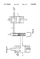
- FIG. 1 illustrates diagrammatically and in elevation a dosing apparatus for filling simultaneously or in sequence into a container a thick particulate/liquid mixture and a thin liquid, the apparatus being shown at a "ready to fill" stage of operation,
- FIG. 2 is a diagram similar to FIG. 1, but with the apparatus in a filling stage of its operation
- FIG. 3 is a diagram similar to FIG. 1 but of the apparatus in a nozzle-flushing stage of its operation
- FIG. 4 is a diagram similar to FIG. 1, but with the apparatus in a re-charging stage of its operation
- FIG. 5 shows a vertical sectional view through a piston-and-cylinder device of the apparatus
- FIG. 6 shows an elevation of the apparatus
- FIG. 7 shows a plan view of apparatus
- FIG. 8 shows a vertical section through a piston-and-cylinder device of a modified version of the apparatus.
- the apparatus is for filling a container 1 with a thick particulate/liquid mixture and with a thin liquid, for example such as disclosed in our co-pending British Patent Application 8631049.
- the mixture can be a liquid containing vegetable pieces, and the thin liquid can be a water-like sauce.
- the mixture and the liquid are filled into the container 1 by a piston-and-cylinder device 2, whereof the internal peripheral surface of the cylinder is formed with a mixture inlet port 3 and a liquid inlet port 4.
- the port 3 is connected via a conduit 5 to a piston-and-cylinder device 6 which acts as a dosing device for the mixture.
- the mixture is supplied to the device 6 via a rotary plug valve 7.
- the port 4 is connected via a conduit 8 and a two-way rotary plug valve 9 to a piston-and-cylinder device 10 serving as a dosing device for the liquid, which is supplied to the device 10 via the valve 9.
- the device 2 may thus be remote from the devices 6 and 10.
- the valves 7 and 9 are shown as rotary plug valves, they can be of any suitable type.
- the device 2 includes a vertical cylinder 11 in which a piston 12 is vertically reciprocal by, for example, an hydraulic drive (not shown).
- the piston 12 is connected to a piston rod 15 and includes an upper part formed coaxially with a peripheral annular channel 16 and provided, immediately above and below the channel 16, with seals 17 and 18.
- the port 4 opens onto an annular groove 19 (which may be omitted if desired) in the internal peripheral surface of the cylinder 11, which groove is in permanent and constantly full communication with the channel 16. Thus there is always a free path for the liquid flow from the port 4 into the chamber 16.
- the lower part of the piston 12 is formed coaxially with an internal bore 20 which widens steadily outwardly as it approaches the lower axial end of the piston 12 and is thereby of frusto-conical form as it approaches that axial end.
- the mouth of the conduit 20 at that end is provided with a cover 21 in the form of a gauze disc of which the holes are sufficiently small to prevent the liquid from dripping therefrom under gravity.
- the diameter of the mouth of the conduit 20 at the cover 21 is, as near as practicable, the full diameter of the nozzle of the cylinder 11.
- the cover 21 is the largest possible, fine-mesh-gauze disc.
- the upper end of the bore 20 communicates within a diametral intersecting bore 22 linking the channel 16 to the conduit 20.
- the port 3 is maintained closed by the peripheral surface of the piston 12, the dosing devices 6 and 10 are charged, each to an adjustable, set extent, the valve 7 is closed, and the valve 9 is closed against supply of liquid to the device 10 but open for supply of liquid from the device 10 to the conduit 8.
- the piston 12 is lifted to its open position shown in FIG. 2, in which position the lower axial end of the piston 12 is clear of and faces towards the port 3.
- the piston of the device 6 can now be moved inwards to discharge the mixture through the port 3 and the nozzle provided by the lower end of the cylinder 11.
- the piston of the device 10 may also be moved inwards to discharge the liquid via the port 4, the channel 16, the conduit 20 and that nozzle into the container 1.
- the piston of the device 6 stops moving and the piston 12 is lowered into closed position shown in FIG. 3, so that the port 3 is closed and, not only does the rim of the mouth of the piston 12 scavenge the internal peripheral surface of the cylinder 11, but also the liquid continuing for a short time to be supplied by the device 10 and thus continuing to debouch from the conduit 20 washes the cover 21 and the internal peripheral surface of the cylinder 11 below the cover 21.
- the rim of the mouth of the conduit 20 has arrived at the rim of the nozzle of the cylinder 11, as seen in FIG. 5.
- valve 7 is opened and the piston of the device 6 is moved outwards to draw the mixture into the device 6; whilst the valve 9 is turned to close the device 10 off from communication with the conduit 8 and the piston of the device 10 is moved outwards to draw in the liquid through the valve 9 from the liquid supply.
- the apparatus is then brought to the stage shown in FIG. 1 and the cycle of operation recommences.
- the design of the device 2 is such that, as the piston 12 rises and falls there is no change in volume within the liquid supply path in the apparatus. In particular, the volume of the liquid in the cylinder 11 remains unchanged.
- FIGS. 6 and 7 serves to fill four parallel lines 1A to 1D of containers 1 as they are advanced below four devices 2, the latter being connected by four pipes 5 to respective devices 6 and by four pipes 8 to respective devices 10.
- the devices 6 and 10 are mounted in a supporting frame 33.
- the four rotary plug valves 7 are driven by respective motors 34, whilst the four rotary plug valves 9 are driven by respective motors 35.
- the pistons of the devices 6 and 10 are driven by motors 36 and 37, respectively.
- a drive 38 operates the devices 2.
- the device 2 shown in FIG. 8 differs from the device 2 described with reference to FIGS. 1 to 5 in having a vent tube 30 leading to the liquid supply, the piston 12 extended upwards to carry a seal 31 spaced above the seal 17, and the cylinder 11 provided internally and co-axially with an annular recess 32.
- the height of the recess 32 is slightly less than the spacing between the seals 17 and 31.
- This arrangement provides for simple automatic air venting, whereby any air entering the liquid section of the device 2 above the cover 21 is vented to the liquids supply tank (not shown). It is important that air is not allowed to accumulate in the liquid section of the device 2. The presence of even quite small amounts of air could adversely affect the cleanliness of fill cut-off.
- the venting is of particular benefit when filling small amounts of liquid, where there is insufficient flow-through to clear any air from the device 2.
- the apparatus is particularly applicable to sophisticated UHT products and is designed to fill cleanly a combination of particulate and liquid products. It allows full control of the proportions and quantities of each product phase and also of the rates of fill and timings throughout the filling cycle to be provided.
- the apparatus is particularly suitable for incorporation in a fully aseptic system.
- the apparatus described with reference to the drawings is very versatile, particularly as regards the rates of fill of the mixture and of the liquid, as regards the proportions of mixture to liquid, and as regards the timing of the filling of the liquid in relation to the filling of the mixture, all of which can be adjusted by appropriate timing and speed-adjustment of the movements of the pistons of the devices 2, 6 and 10, in particular.
- it is not necessary to discharge the liquid at the same time as the mixture. It is however highly desirable at least to finish the fill with a small amount of the liquid to clean the nozzle.
Abstract
A dosing system for filling containers with a particulate/liquid mixture includes three piston-and-cylinder devices, of which a first device delivers the mixture downwards to containers advanced beneath it, a second device feeds a thick particulate/liquid mixture via a conduit to the first device, and the third device feeds a thin liquid via a conduit to the first device. A liquid supply port is disposed peripherally in the cylinder of the first device and swept by the piston thereof, and a conduit in continuous communication with the port extends through the piston to a lower axial end of the piston.
Description
This is a continuation of co-pending application Ser. No. 07/734,230 filed on Jul. 22, 1991, now abandoned, which is a continuation of application Ser. No. 07/159,243 filed Feb. 23, 1988, which issued as U.S. Pat. No. 5,052,591.
1. Field of the Invention
This invention relates to a dosing system, especially for filling containers with a particulate/liquid mixture.
2. Description of the Prior Art
GB 2089440 A discloses a pump for metering two fluids, particularly a relatively thick fluid, such as a suspension of solid particles in a liquid, with an homogeneous liquid. The pump comprises a first cylinder containing a floating, solid, first piston and having an inlet conduit and an outlet conduit, a second piston in a second cylinder and for closing the communication between the first cylinder and its inlet conduit and between the first cylinder and its outlet conduit, alternately, the first piston drawing in the thick fluid from the inlet conduit and discharging it into the outlet conduit, and a third cylinder having a piston for drawing in the thin fluid from a second inlet conduit which piston has least one port provided with one more valves through which the thin fluid flow to occupy the space between the first and third pistons where it can transmit the motion of the third piston to the first piston, and a by-pass for conveying thin fluid from the space between the pistons to the outlet conduit.
The by-pass serves to feed thin fluid to inwardly directed nozzles on the lower end of the outlet conduit to inject thin fluid into the discharge section to wash away traces of the thick fluid from lower end of the second piston and from the internal surface of the discharge section, which converges downwardly from just above the level of the nozzles. This arrangement has a number of disadvantages. Firstly, the provision of internal surface portions below the level of the lower end of the stroke of the second piston encourages dripping from the outflow mouth of the outlet conduit. Secondly, the liquid jets may be unsuccessful in preventing an accumulation of sticky substances upon the piston end surface and those internal surface portions. Thirdly, the nozzles may become clogged with particulates and are then awkward to clean.
According to one aspect of the present invention, there is provided dosing apparatus comprising a piston-and-cylinder device, a peripheral port of the cylinder and swept by the piston as the piston moves between an open position in which an axial end of said piston faces towards said port, and a closed position, drive means for reciprocating the piston in the cylinder, and means for supplying a flowable material to said port, wherein the improvement comprises a conduit extending in said piston and debouching longitudinally of said cylinder at said axial end in the form of a mouth, and means for supplying a liquid to said conduit.
Thus, the dosing apparatus has a simple arrangement whereby flowable material is cleaned away from said axial end and the external wall of said cylinder by said liquid.
It is advantageous if the conduit mouth at said axial end is of a width almost equal to the internal width of the cylinder, so allowing the liquid to act cleansingly over the internal cross-section of the cylinder. It is also advantageous to provide on said mouth a cover formed with through holes distributed over its area, in order to spread the liquid more regularly over then internal cross-sectional area of the cylinder and to deter entry of the flowable material into the mouth. These holes are preferably small enough that surface tension in the liquid prevents liquid from dripping from the mouth under gravity.
According to another aspect of the present invention, there is provided dosing apparatus comprising a piston-and-cylinder device, a first peripheral port of the cylinder and swept by the piston as the piston moves between an open position in which an axial end of said piston faces towards said port and a closed position, means for supplying a flowable material to said port, drive means for reciprocating the piston in the cylinder, a second peripheral port of said cylinder situated after the first port in the direction from said closed position to said open position for supplying to said cylinder a liquid, wherein the improvement comprises the arrangement being such that the reciprocation of said piston in said cylinder does not substantially change the volume of said liquid in said cylinder.
Owing to this arrangement, any drawing-in of air because of substantial change in the volume of liquid present is avoided.
According to a third aspect of the present invention, there is provided dosing apparatus, comprising a piston-and-cylinder device having an upwardly extending longitudinal axis, surface portions of the piston and the cylinder defining an annular chamber in said device and co-axially encircling said piston, a peripheral port of the cylinder opening onto said chamber for supplying a liquid to said chamber, and drive means for reciprocating the piston in the cylinder, wherein the improvement comprises venting means communicating with the upper extremity of said chamber for venting any gaseous matter arriving at the upper extremity of said chamber.
Owing to the venting means, any air introduced into the device is vented away to prevent it from impairing the efficiency of the dosing.
In order that the invention may be clearly understood and readily carried into effect, reference will now be made, by way of example, to the accompanying drawings, in which:-
FIG. 1 illustrates diagrammatically and in elevation a dosing apparatus for filling simultaneously or in sequence into a container a thick particulate/liquid mixture and a thin liquid, the apparatus being shown at a "ready to fill" stage of operation,
FIG. 2 is a diagram similar to FIG. 1, but with the apparatus in a filling stage of its operation,
FIG. 3 is a diagram similar to FIG. 1 but of the apparatus in a nozzle-flushing stage of its operation,
FIG. 4 is a diagram similar to FIG. 1, but with the apparatus in a re-charging stage of its operation,
FIG. 5 shows a vertical sectional view through a piston-and-cylinder device of the apparatus,
FIG. 6 shows an elevation of the apparatus,
FIG. 7 shows a plan view of apparatus, and
FIG. 8 shows a vertical section through a piston-and-cylinder device of a modified version of the apparatus.
Referring to FIGS. 1 to 5, the apparatus is for filling a container 1 with a thick particulate/liquid mixture and with a thin liquid, for example such as disclosed in our co-pending British Patent Application 8631049. The mixture can be a liquid containing vegetable pieces, and the thin liquid can be a water-like sauce.
The mixture and the liquid are filled into the container 1 by a piston-and-cylinder device 2, whereof the internal peripheral surface of the cylinder is formed with a mixture inlet port 3 and a liquid inlet port 4. The port 3 is connected via a conduit 5 to a piston-and-cylinder device 6 which acts as a dosing device for the mixture. The mixture is supplied to the device 6 via a rotary plug valve 7. The port 4 is connected via a conduit 8 and a two-way rotary plug valve 9 to a piston-and-cylinder device 10 serving as a dosing device for the liquid, which is supplied to the device 10 via the valve 9. The device 2 may thus be remote from the devices 6 and 10. Although the valves 7 and 9 are shown as rotary plug valves, they can be of any suitable type.
Referring particularly to FIG. 5, the device 2 includes a vertical cylinder 11 in which a piston 12 is vertically reciprocal by, for example, an hydraulic drive (not shown). The piston 12 is connected to a piston rod 15 and includes an upper part formed coaxially with a peripheral annular channel 16 and provided, immediately above and below the channel 16, with seals 17 and 18. The port 4 opens onto an annular groove 19 (which may be omitted if desired) in the internal peripheral surface of the cylinder 11, which groove is in permanent and constantly full communication with the channel 16. Thus there is always a free path for the liquid flow from the port 4 into the chamber 16. The lower part of the piston 12 is formed coaxially with an internal bore 20 which widens steadily outwardly as it approaches the lower axial end of the piston 12 and is thereby of frusto-conical form as it approaches that axial end. The mouth of the conduit 20 at that end is provided with a cover 21 in the form of a gauze disc of which the holes are sufficiently small to prevent the liquid from dripping therefrom under gravity. The diameter of the mouth of the conduit 20 at the cover 21 is, as near as practicable, the full diameter of the nozzle of the cylinder 11. Moreover, the cover 21 is the largest possible, fine-mesh-gauze disc. The upper end of the bore 20 communicates within a diametral intersecting bore 22 linking the channel 16 to the conduit 20.
The operation of the apparatus will now be described, assuming a requirement to fill the container 1 with a solid/liquid mixture and a liquid.
In the ready-to-fill stage shown in FIG. 1, the port 3 is maintained closed by the peripheral surface of the piston 12, the dosing devices 6 and 10 are charged, each to an adjustable, set extent, the valve 7 is closed, and the valve 9 is closed against supply of liquid to the device 10 but open for supply of liquid from the device 10 to the conduit 8. Firstly, the piston 12 is lifted to its open position shown in FIG. 2, in which position the lower axial end of the piston 12 is clear of and faces towards the port 3. The piston of the device 6 can now be moved inwards to discharge the mixture through the port 3 and the nozzle provided by the lower end of the cylinder 11. The piston of the device 10 may also be moved inwards to discharge the liquid via the port 4, the channel 16, the conduit 20 and that nozzle into the container 1. When the desired dose of mixture has been discharged into the container 1, the piston of the device 6 stops moving and the piston 12 is lowered into closed position shown in FIG. 3, so that the port 3 is closed and, not only does the rim of the mouth of the piston 12 scavenge the internal peripheral surface of the cylinder 11, but also the liquid continuing for a short time to be supplied by the device 10 and thus continuing to debouch from the conduit 20 washes the cover 21 and the internal peripheral surface of the cylinder 11 below the cover 21. In the closed position of the piston 12, the rim of the mouth of the conduit 20 has arrived at the rim of the nozzle of the cylinder 11, as seen in FIG. 5. In order to recharge the dosing devices 6 and 10, as shown in FIG. 4, the valve 7 is opened and the piston of the device 6 is moved outwards to draw the mixture into the device 6; whilst the valve 9 is turned to close the device 10 off from communication with the conduit 8 and the piston of the device 10 is moved outwards to draw in the liquid through the valve 9 from the liquid supply. The apparatus is then brought to the stage shown in FIG. 1 and the cycle of operation recommences.
In setting up the apparatus ready to fill, first of all air is totally flushed out of the product supply pipes and the channel 16 and the conduit 20 are completely filled with liquid. During liquid filling, the conduit 20 and its supply arrangement are kept totally full of liquid. The system is completely closed except for the cover 21 which causes the liquid to be held in the conduit 20 under the surface tension effect of the liquid. Thus, the liquid can only pass through the cover 21 as more liquid is fed in from the supply. Therefore, the system provides a very clean, positive, cut-off action at the end of each fill. Moreover, solids do not penetrate the cover 21 and any adhering to the outside of the cover 21 are immediately washed off by the liquid fill.
The design of the device 2 is such that, as the piston 12 rises and falls there is no change in volume within the liquid supply path in the apparatus. In particular, the volume of the liquid in the cylinder 11 remains unchanged.
The apparatus shown in detail in FIGS. 6 and 7 serves to fill four parallel lines 1A to 1D of containers 1 as they are advanced below four devices 2, the latter being connected by four pipes 5 to respective devices 6 and by four pipes 8 to respective devices 10. The devices 6 and 10 are mounted in a supporting frame 33. The four rotary plug valves 7 are driven by respective motors 34, whilst the four rotary plug valves 9 are driven by respective motors 35. The pistons of the devices 6 and 10 are driven by motors 36 and 37, respectively. A drive 38 operates the devices 2.
The device 2 shown in FIG. 8 differs from the device 2 described with reference to FIGS. 1 to 5 in having a vent tube 30 leading to the liquid supply, the piston 12 extended upwards to carry a seal 31 spaced above the seal 17, and the cylinder 11 provided internally and co-axially with an annular recess 32. The height of the recess 32 is slightly less than the spacing between the seals 17 and 31. As the piston 12 reciprocates, the volume of thin liquid in the cylinder 11 below the seal 31 remains constant.
This arrangement provides for simple automatic air venting, whereby any air entering the liquid section of the device 2 above the cover 21 is vented to the liquids supply tank (not shown). It is important that air is not allowed to accumulate in the liquid section of the device 2. The presence of even quite small amounts of air could adversely affect the cleanliness of fill cut-off. The venting is of particular benefit when filling small amounts of liquid, where there is insufficient flow-through to clear any air from the device 2.
In operation, as the piston 12 moves, any air present, rising to the top, is allowed to pass first the seal 17 and then the seal 31, and thus finally freed to vent to the liquid supply tank.
The apparatus is particularly applicable to sophisticated UHT products and is designed to fill cleanly a combination of particulate and liquid products. It allows full control of the proportions and quantities of each product phase and also of the rates of fill and timings throughout the filling cycle to be provided. The apparatus is particularly suitable for incorporation in a fully aseptic system.
The apparatus described with reference to the drawings is very versatile, particularly as regards the rates of fill of the mixture and of the liquid, as regards the proportions of mixture to liquid, and as regards the timing of the filling of the liquid in relation to the filling of the mixture, all of which can be adjusted by appropriate timing and speed-adjustment of the movements of the pistons of the devices 2, 6 and 10, in particular. Thus, it is not necessary to discharge the liquid at the same time as the mixture. It is however highly desirable at least to finish the fill with a small amount of the liquid to clean the nozzle.
Claims (3)
1. Dosing apparatus comprising a piston-and-cylinder device, the piston having a cylindrical external peripheral surface and an axial end, and the cylinder having a cylindrical internal peripheral surface and a peripheral port debouching at said cylindrical internal peripheral surface, said peripheral port being swept by the piston as the piston moves between an open position in which said peripheral port is open and in which said axial end of said piston faces towards said port, and a closed position in which said cylindrical external peripheral surface closes said port and extends face-to-face with said cylindrical internal peripheral surface in both longitudinal directions of said cylinder from said peripheral port, drive means for reciprocating the piston in the cylinder, means for supplying a flowable material to said port, a conduit extending in said piston and debouching longitudinally of said cylinder at said axial end in the form of a mouth, means for supplying a liquid to said conduit, and a cover provided on said mouth and having an inner face and an outer face and formed with through holes distributed over its area, said holes being small enough that surface tension in the liquid prevents liquid from dripping from the mouth under gravity, said outer face of said cover serving to contact said flowable material, said holes enabling said liquid to wash away such flowable material contacting said outer face, and said cylinder having an outlet for said flowable material and said liquid.
2. Dosing apparatus comprising a piston-and-cylinder device, the piston having a cylindrical external peripheral surface and an axial end, and the cylinder having a cylindrical internal peripheral surface and a peripheral port debouching at said cylindrical internal peripheral surface, said peripheral port being swept by the piston as the piston moves between an open position in which said peripheral port is open and in which said axial end of said piston faces towards said port, and a closed position in which said cylindrical external peripheral surface closes said port and extends face-to-face with said cylindrical internal peripheral surface in both longitudinal directions of said cylinder from said peripheral port, drive means for reciprocating the piston in the cylinder, means for supplying a flowable material to said port, a conduit extending in said piston and debouching longitudinally of said cylinder at said axial end in the form of a mouth of a width slightly less than the internal width of said cylinder, means for supplying a liquid to said conduit, a cover provided on said mouth and formed with through holes distributed over its area, said holes being small enough that surface tension in the liquid prevents liquid from dripping from the mouth under gravity, and said cylinder having an outlet for both said flowable material and said liquid.
3. Dosing apparatus comprising a fluid material metering device for metering supply of a particulates-containing fluid material, a liquid metering device for metering supply of a liquid, a filling nozzle comprised of a piston-and-cylinder device for filling containers with said fluid material and said liquid, a fluid material duct communicating said fluid material metering device with said filling nozzle at a fluid material inlet for leading said fluid material to said filling nozzle, a liquid duct communicating said liquid metering device with said filling nozzle at a liquid inlet for leading said liquid to said filling nozzle, and a vent hole serving to vent gaseous material from said liquid in the cylinder of said piston-and-cylinder device, said piston-and-cylinder device having a longitudinal axis extending downward towards an outlet mouth of the cylinder of said piston-and-cylinder device, said vent hole being provided in an uppermost region of said cylinder.
Priority Applications (1)
| Application Number | Priority Date | Filing Date | Title |
|---|---|---|---|
| US08/054,890 US5344052A (en) | 1987-02-24 | 1993-04-28 | Dosing system |
Applications Claiming Priority (5)
| Application Number | Priority Date | Filing Date | Title |
|---|---|---|---|
| GB8704343 | 1987-02-24 | ||
| GB878704343A GB8704343D0 (en) | 1987-02-24 | 1987-02-24 | Dosing system |
| US07/159,243 US5052591A (en) | 1987-02-24 | 1988-02-23 | Dosing system |
| US73423091A | 1991-07-22 | 1991-07-22 | |
| US08/054,890 US5344052A (en) | 1987-02-24 | 1993-04-28 | Dosing system |
Related Parent Applications (1)
| Application Number | Title | Priority Date | Filing Date |
|---|---|---|---|
| US73423091A Continuation | 1987-02-24 | 1991-07-22 |
Publications (1)
| Publication Number | Publication Date |
|---|---|
| US5344052A true US5344052A (en) | 1994-09-06 |
Family
ID=10612859
Family Applications (2)
| Application Number | Title | Priority Date | Filing Date |
|---|---|---|---|
| US07/159,243 Expired - Lifetime US5052591A (en) | 1987-02-24 | 1988-02-23 | Dosing system |
| US08/054,890 Expired - Lifetime US5344052A (en) | 1987-02-24 | 1993-04-28 | Dosing system |
Family Applications Before (1)
| Application Number | Title | Priority Date | Filing Date |
|---|---|---|---|
| US07/159,243 Expired - Lifetime US5052591A (en) | 1987-02-24 | 1988-02-23 | Dosing system |
Country Status (11)
| Country | Link |
|---|---|
| US (2) | US5052591A (en) |
| EP (1) | EP0280537B1 (en) |
| JP (1) | JP2655522B2 (en) |
| KR (1) | KR890700516A (en) |
| AT (1) | ATE68761T1 (en) |
| CA (1) | CA1284790C (en) |
| DE (1) | DE3865700D1 (en) |
| GB (1) | GB8704343D0 (en) |
| IL (1) | IL85531A0 (en) |
| WO (1) | WO1988006552A1 (en) |
| ZA (1) | ZA881304B (en) |
Cited By (11)
| Publication number | Priority date | Publication date | Assignee | Title |
|---|---|---|---|---|
| US20070227620A1 (en) * | 2004-04-13 | 2007-10-04 | Mitsuru Kunii | Liquid Filling Nozzle |
| US20100308074A1 (en) * | 2007-08-31 | 2010-12-09 | Pfizer, Inc. | Liquid pump |
| US20110030849A1 (en) * | 2009-08-07 | 2011-02-10 | Swagelok Company | Low temperature carburization under soft vacuum |
| WO2011120731A1 (en) * | 2010-03-30 | 2011-10-06 | Robert Bosch Gmbh | Vorrichtung zum dosieren und abgeben wenigstens zweier, insbesondere hinsichtlich ihrer konsistenz unterschiedlicher produkte in einen verpackungsbehälter |
| US20140326360A1 (en) * | 2011-11-28 | 2014-11-06 | Robert Bosch Gmbh | Device for simultaneously filling at least two foods of different compositions into one container |
| US9725225B1 (en) * | 2012-02-24 | 2017-08-08 | Dl Technology, Llc | Micro-volume dispense pump systems and methods |
| US11161636B2 (en) * | 2016-10-25 | 2021-11-02 | Synerlink | Methods and devices for filling cups, packaging lines for cups |
| US20220212817A1 (en) * | 2021-01-05 | 2022-07-07 | Société des Produits Nestlé S.A. | Apparatuses and methods for enclosing a filling in a food product |
| US11420225B1 (en) | 2009-05-01 | 2022-08-23 | DL Technology, LLC. | Material dispense tips and methods for forming the same |
| US11648581B1 (en) | 2007-02-20 | 2023-05-16 | DL Technology, LLC. | Method for manufacturing a material dispense tip |
| US11746656B1 (en) | 2019-05-13 | 2023-09-05 | DL Technology, LLC. | Micro-volume dispense pump systems and methods |
Families Citing this family (18)
| Publication number | Priority date | Publication date | Assignee | Title |
|---|---|---|---|---|
| GB8704343D0 (en) * | 1987-02-24 | 1987-04-01 | Odin Dev Ltd | Dosing system |
| GB9027859D0 (en) * | 1990-12-21 | 1991-02-13 | Cmb Foodcan Plc | Metering apparatus |
| CA2132333C (en) * | 1992-03-17 | 1998-07-07 | James W. Schmitkons | Two-component dispensing system |
| JPH0632301A (en) * | 1992-07-13 | 1994-02-08 | Snow Brand Milk Prod Co Ltd | Method and device for packing solid/liquid product to be packed |
| US5687779A (en) * | 1992-09-17 | 1997-11-18 | Tetra Laval Holdings & Finance S.A. | Packaging machine system for filling primary and secondary products into a container |
| FR2708563B1 (en) * | 1993-08-02 | 1995-10-27 | Erca | Unit and method for dosing and distribution of liquid and / or pasty products. |
| US5499745A (en) * | 1994-02-18 | 1996-03-19 | Nordson Corporation | Apparatus for mixing and dispensing two chemically reactive materials |
| CA2201290A1 (en) * | 1994-09-29 | 1996-04-04 | Karl-Gunnar Axelsson | Packaging machine system for filling primary and secondary products into a container |
| US6065510A (en) * | 1994-09-29 | 2000-05-23 | Tetra Laval Holdings & Finance, Sa | Fill system for primary and secondary products |
| JP3866901B2 (en) * | 2000-03-24 | 2007-01-10 | 大成ラミック株式会社 | Package filling device |
| US6821096B2 (en) * | 2002-08-30 | 2004-11-23 | Illinois Tool Works Inc. | Multiple component metering and dispensing system |
| DE102005018243A1 (en) | 2005-04-19 | 2006-10-26 | Henkel Kgaa | Process for the preparation of liquid preparations with solids content |
| US8376191B2 (en) * | 2008-09-30 | 2013-02-19 | Modern Packaging Inc. | Submergible volumetric filling device and method including cone-shaped switching valve capabilities |
| JP2011254726A (en) * | 2010-06-07 | 2011-12-22 | Meka:Kk | Soup dispenser |
| EP3169204B1 (en) * | 2014-07-18 | 2019-10-09 | PI-Design AG | Kitchen appliance for processing foodstuff |
| CN107787187A (en) * | 2015-06-25 | 2018-03-09 | 荷兰联合利华有限公司 | With the method for frozen confectionery filling container |
| GB201703549D0 (en) * | 2017-03-06 | 2017-04-19 | Hodges & Drake Design Ltd | Apparatus for dispensing a flowable product |
| US11104461B2 (en) | 2017-09-15 | 2021-08-31 | Campbell Soup Company | Two-phase filling apparatus and methods |
Citations (34)
| Publication number | Priority date | Publication date | Assignee | Title |
|---|---|---|---|---|
| US2303913A (en) * | 1941-04-11 | 1942-12-01 | Lee C Collinge | Dispenser for disinfectants |
| US2850990A (en) * | 1956-07-19 | 1958-09-09 | Marlin B Rasmusson | Confection mold filler |
| US3221948A (en) * | 1962-09-26 | 1965-12-07 | Ernest S Kalist | Metering and injection device |
| US3550814A (en) * | 1968-10-17 | 1970-12-29 | Campbell Soup Co | Mixing and dispensing unit |
| US3643688A (en) * | 1969-01-28 | 1972-02-22 | Noll Maschfab Gmbh | Device for the continuous mixing of beverage components in a predetermined quantity ratio |
| DE1786591A1 (en) * | 1966-11-15 | 1975-01-09 | Owens Illinois Inc | DEVICE FOR FILLING FROM TOP OPEN CONTAINERS WITH ROUND SIDE WALL |
| US3865281A (en) * | 1970-05-18 | 1975-02-11 | Owens Illinois Inc | Apparatus for filling containers |
| US3975128A (en) * | 1973-05-29 | 1976-08-17 | Krauss-Maffei Aktiengesellschaft | System for filling a mold with reactive synthetic-resin components |
| DE2539656A1 (en) * | 1975-09-05 | 1977-03-10 | Scholle Corp | Valve head for filling container with viscous material - has reciprocable valve member with fluid passage to outlet for cleaning |
| US4073408A (en) * | 1975-04-10 | 1978-02-14 | Schloemann-Siemag Aktiengesellschaft | Apparatus for mixing plastics |
| US4119126A (en) * | 1976-04-23 | 1978-10-10 | Faat Khatovich Nabiullin | Device for introducing fillers and terminal into galvanic cell |
| FR2392252A1 (en) * | 1977-05-24 | 1978-12-22 | Hassia Verpackung Gmbh | Foodstuff metering pump or valve with steam scavenging chamber - has closure piston rod through hollow metering piston rod with steam inlet and outlet |
| US4178929A (en) * | 1976-12-22 | 1979-12-18 | Robert Bosch Gmbh | Dosing device for germ-free measurements and filling of liquid material |
| US4184613A (en) * | 1974-12-30 | 1980-01-22 | Phillips Petroleum Company | Apparatus for combining a plurality of viscous streams to form a patterned product |
| US4271989A (en) * | 1979-03-27 | 1981-06-09 | Physics International Company | Micro-metering system |
| US4273263A (en) * | 1978-05-13 | 1981-06-16 | Robert Bosch Gmbh | Filling apparatus for fluid media |
| US4324494A (en) * | 1979-11-19 | 1982-04-13 | Umc Industries, Inc. | Drink dispensing |
| GB2089440A (en) * | 1980-12-16 | 1982-06-23 | Nestle Sa | Pump |
| US4371101A (en) * | 1979-10-31 | 1983-02-01 | Zanasi Nigris S.P.A. | Filtering screen for use in apparatus for the dosing of powdered material |
| US4397407A (en) * | 1980-04-03 | 1983-08-09 | Bayer Aktiengesellschaft | Apparatus for the production of a solid-forming or foam-forming mixture composed of at least two flowable reaction components and fillers |
| US4398577A (en) * | 1980-08-28 | 1983-08-16 | Sauer Robert L | Flowable product metering and dispensing machine |
| US4410108A (en) * | 1980-02-11 | 1983-10-18 | Elmar Industries, Inc. | Pressure-actuated valve for use with positive displacement filling machine |
| US4460025A (en) * | 1982-01-29 | 1984-07-17 | Scholle William J | Filling valve assembly with fiber shearing edge |
| US4479758A (en) * | 1980-12-16 | 1984-10-30 | Societe D'assistance Technique Pour Produits Nestle S.A. | Piston filler |
| DE3506135A1 (en) * | 1985-02-22 | 1986-08-28 | ASEA GmbH, 5340 Bad Honnef | APPLICATION DEVICE FOR APPLYING A TOE LIQUID |
| US4630972A (en) * | 1984-10-29 | 1986-12-23 | Utilitech, Incorporated | Impulse injector apparatus |
| US4643228A (en) * | 1984-03-02 | 1987-02-17 | Sigma Enterprises, Inc. | Convertible high or low pressure pilot valve |
| US4676279A (en) * | 1985-05-30 | 1987-06-30 | Campbell Soup Company | Filler for aseptic dispensing of particulate garnish |
| EP0232943A1 (en) * | 1986-02-14 | 1987-08-19 | Tetra Dev-Co | A method and an arrangement on packing machines |
| US4699297A (en) * | 1984-01-03 | 1987-10-13 | Raque Food Systems, Inc. | Aseptic filling arrangement |
| GB2192859A (en) * | 1986-07-21 | 1988-01-27 | Benz & Hilgers Gmbh | Fluid metering device with arrangement to prevent dripping from nozzle |
| US4823992A (en) * | 1986-09-03 | 1989-04-25 | Afros S.P.A. | Metering device for feeding liquids to a mixing head |
| US4913202A (en) * | 1986-10-14 | 1990-04-03 | Cmb Packaging (Uk) Limited | Filling packaging containers |
| US5052591A (en) * | 1987-02-24 | 1991-10-01 | Odin Development Ltd. | Dosing system |
Family Cites Families (1)
| Publication number | Priority date | Publication date | Assignee | Title |
|---|---|---|---|---|
| JPS60214844A (en) * | 1984-04-10 | 1985-10-28 | Zenji Uchiyama | Device for feeding simultaneously plural ingredient for packing into cake |
-
1987
- 1987-02-24 GB GB878704343A patent/GB8704343D0/en active Pending
-
1988
- 1988-02-23 US US07/159,243 patent/US5052591A/en not_active Expired - Lifetime
- 1988-02-23 CA CA000559592A patent/CA1284790C/en not_active Expired - Lifetime
- 1988-02-24 EP EP88301595A patent/EP0280537B1/en not_active Expired - Lifetime
- 1988-02-24 WO PCT/GB1988/000128 patent/WO1988006552A1/en unknown
- 1988-02-24 JP JP63502332A patent/JP2655522B2/en not_active Expired - Fee Related
- 1988-02-24 KR KR1019880701333A patent/KR890700516A/en not_active Application Discontinuation
- 1988-02-24 AT AT88301595T patent/ATE68761T1/en not_active IP Right Cessation
- 1988-02-24 IL IL85531A patent/IL85531A0/en unknown
- 1988-02-24 ZA ZA881304A patent/ZA881304B/en unknown
- 1988-02-24 DE DE8888301595T patent/DE3865700D1/en not_active Expired - Lifetime
-
1993
- 1993-04-28 US US08/054,890 patent/US5344052A/en not_active Expired - Lifetime
Patent Citations (34)
| Publication number | Priority date | Publication date | Assignee | Title |
|---|---|---|---|---|
| US2303913A (en) * | 1941-04-11 | 1942-12-01 | Lee C Collinge | Dispenser for disinfectants |
| US2850990A (en) * | 1956-07-19 | 1958-09-09 | Marlin B Rasmusson | Confection mold filler |
| US3221948A (en) * | 1962-09-26 | 1965-12-07 | Ernest S Kalist | Metering and injection device |
| DE1786591A1 (en) * | 1966-11-15 | 1975-01-09 | Owens Illinois Inc | DEVICE FOR FILLING FROM TOP OPEN CONTAINERS WITH ROUND SIDE WALL |
| US3550814A (en) * | 1968-10-17 | 1970-12-29 | Campbell Soup Co | Mixing and dispensing unit |
| US3643688A (en) * | 1969-01-28 | 1972-02-22 | Noll Maschfab Gmbh | Device for the continuous mixing of beverage components in a predetermined quantity ratio |
| US3865281A (en) * | 1970-05-18 | 1975-02-11 | Owens Illinois Inc | Apparatus for filling containers |
| US3975128A (en) * | 1973-05-29 | 1976-08-17 | Krauss-Maffei Aktiengesellschaft | System for filling a mold with reactive synthetic-resin components |
| US4184613A (en) * | 1974-12-30 | 1980-01-22 | Phillips Petroleum Company | Apparatus for combining a plurality of viscous streams to form a patterned product |
| US4073408A (en) * | 1975-04-10 | 1978-02-14 | Schloemann-Siemag Aktiengesellschaft | Apparatus for mixing plastics |
| DE2539656A1 (en) * | 1975-09-05 | 1977-03-10 | Scholle Corp | Valve head for filling container with viscous material - has reciprocable valve member with fluid passage to outlet for cleaning |
| US4119126A (en) * | 1976-04-23 | 1978-10-10 | Faat Khatovich Nabiullin | Device for introducing fillers and terminal into galvanic cell |
| US4178929A (en) * | 1976-12-22 | 1979-12-18 | Robert Bosch Gmbh | Dosing device for germ-free measurements and filling of liquid material |
| FR2392252A1 (en) * | 1977-05-24 | 1978-12-22 | Hassia Verpackung Gmbh | Foodstuff metering pump or valve with steam scavenging chamber - has closure piston rod through hollow metering piston rod with steam inlet and outlet |
| US4273263A (en) * | 1978-05-13 | 1981-06-16 | Robert Bosch Gmbh | Filling apparatus for fluid media |
| US4271989A (en) * | 1979-03-27 | 1981-06-09 | Physics International Company | Micro-metering system |
| US4371101A (en) * | 1979-10-31 | 1983-02-01 | Zanasi Nigris S.P.A. | Filtering screen for use in apparatus for the dosing of powdered material |
| US4324494A (en) * | 1979-11-19 | 1982-04-13 | Umc Industries, Inc. | Drink dispensing |
| US4410108A (en) * | 1980-02-11 | 1983-10-18 | Elmar Industries, Inc. | Pressure-actuated valve for use with positive displacement filling machine |
| US4397407A (en) * | 1980-04-03 | 1983-08-09 | Bayer Aktiengesellschaft | Apparatus for the production of a solid-forming or foam-forming mixture composed of at least two flowable reaction components and fillers |
| US4398577A (en) * | 1980-08-28 | 1983-08-16 | Sauer Robert L | Flowable product metering and dispensing machine |
| GB2089440A (en) * | 1980-12-16 | 1982-06-23 | Nestle Sa | Pump |
| US4479758A (en) * | 1980-12-16 | 1984-10-30 | Societe D'assistance Technique Pour Produits Nestle S.A. | Piston filler |
| US4460025A (en) * | 1982-01-29 | 1984-07-17 | Scholle William J | Filling valve assembly with fiber shearing edge |
| US4699297A (en) * | 1984-01-03 | 1987-10-13 | Raque Food Systems, Inc. | Aseptic filling arrangement |
| US4643228A (en) * | 1984-03-02 | 1987-02-17 | Sigma Enterprises, Inc. | Convertible high or low pressure pilot valve |
| US4630972A (en) * | 1984-10-29 | 1986-12-23 | Utilitech, Incorporated | Impulse injector apparatus |
| DE3506135A1 (en) * | 1985-02-22 | 1986-08-28 | ASEA GmbH, 5340 Bad Honnef | APPLICATION DEVICE FOR APPLYING A TOE LIQUID |
| US4676279A (en) * | 1985-05-30 | 1987-06-30 | Campbell Soup Company | Filler for aseptic dispensing of particulate garnish |
| EP0232943A1 (en) * | 1986-02-14 | 1987-08-19 | Tetra Dev-Co | A method and an arrangement on packing machines |
| GB2192859A (en) * | 1986-07-21 | 1988-01-27 | Benz & Hilgers Gmbh | Fluid metering device with arrangement to prevent dripping from nozzle |
| US4823992A (en) * | 1986-09-03 | 1989-04-25 | Afros S.P.A. | Metering device for feeding liquids to a mixing head |
| US4913202A (en) * | 1986-10-14 | 1990-04-03 | Cmb Packaging (Uk) Limited | Filling packaging containers |
| US5052591A (en) * | 1987-02-24 | 1991-10-01 | Odin Development Ltd. | Dosing system |
Cited By (19)
| Publication number | Priority date | Publication date | Assignee | Title |
|---|---|---|---|---|
| US7743798B2 (en) * | 2004-04-13 | 2010-06-29 | Kao Corporation | Liquid filling nozzle |
| US20070227620A1 (en) * | 2004-04-13 | 2007-10-04 | Mitsuru Kunii | Liquid Filling Nozzle |
| US11648581B1 (en) | 2007-02-20 | 2023-05-16 | DL Technology, LLC. | Method for manufacturing a material dispense tip |
| US20100308074A1 (en) * | 2007-08-31 | 2010-12-09 | Pfizer, Inc. | Liquid pump |
| US11738364B1 (en) | 2009-05-01 | 2023-08-29 | DL Technology, LLC. | Material dispense tips and methods for forming the same |
| US11420225B1 (en) | 2009-05-01 | 2022-08-23 | DL Technology, LLC. | Material dispense tips and methods for forming the same |
| US10156006B2 (en) | 2009-08-07 | 2018-12-18 | Swagelok Company | Low temperature carburization under soft vacuum |
| US20110030849A1 (en) * | 2009-08-07 | 2011-02-10 | Swagelok Company | Low temperature carburization under soft vacuum |
| WO2011120731A1 (en) * | 2010-03-30 | 2011-10-06 | Robert Bosch Gmbh | Vorrichtung zum dosieren und abgeben wenigstens zweier, insbesondere hinsichtlich ihrer konsistenz unterschiedlicher produkte in einen verpackungsbehälter |
| US9505506B2 (en) * | 2011-11-28 | 2016-11-29 | Robert Bosch Gmbh | Device for simultaneously filling at least two foods of different compositions into one container |
| US20140326360A1 (en) * | 2011-11-28 | 2014-11-06 | Robert Bosch Gmbh | Device for simultaneously filling at least two foods of different compositions into one container |
| US10370172B1 (en) | 2012-02-24 | 2019-08-06 | DL Technology, LLC. | Micro-volume dispense pump systems and methods |
| US11059654B1 (en) | 2012-02-24 | 2021-07-13 | DL Technology, LLC. | Micro-volume dispense pump systems and methods |
| US11370596B1 (en) | 2012-02-24 | 2022-06-28 | DL Technology, LLC. | Micro-volume dispense pump systems and methods |
| US9725225B1 (en) * | 2012-02-24 | 2017-08-08 | Dl Technology, Llc | Micro-volume dispense pump systems and methods |
| US11161636B2 (en) * | 2016-10-25 | 2021-11-02 | Synerlink | Methods and devices for filling cups, packaging lines for cups |
| US11746656B1 (en) | 2019-05-13 | 2023-09-05 | DL Technology, LLC. | Micro-volume dispense pump systems and methods |
| US20220212817A1 (en) * | 2021-01-05 | 2022-07-07 | Société des Produits Nestlé S.A. | Apparatuses and methods for enclosing a filling in a food product |
| US11884430B2 (en) * | 2021-01-05 | 2024-01-30 | Société des Produits Nestlé S.A. | Apparatuses and methods for enclosing a filling in a food product |
Also Published As
| Publication number | Publication date |
|---|---|
| US5052591A (en) | 1991-10-01 |
| WO1988006552A1 (en) | 1988-09-07 |
| IL85531A0 (en) | 1988-08-31 |
| JPH01502424A (en) | 1989-08-24 |
| CA1284790C (en) | 1991-06-11 |
| EP0280537B1 (en) | 1991-10-23 |
| JP2655522B2 (en) | 1997-09-24 |
| ATE68761T1 (en) | 1991-11-15 |
| GB8704343D0 (en) | 1987-04-01 |
| DE3865700D1 (en) | 1991-11-28 |
| KR890700516A (en) | 1989-04-25 |
| ZA881304B (en) | 1988-08-23 |
| EP0280537A1 (en) | 1988-08-31 |
Similar Documents
| Publication | Publication Date | Title |
|---|---|---|
| US5344052A (en) | Dosing system | |
| US4410108A (en) | Pressure-actuated valve for use with positive displacement filling machine | |
| US4648421A (en) | Valve device for controlling liquid flow | |
| US4750532A (en) | Device for extracting liquids contained therein and arrangement for filling the device | |
| US5137187A (en) | Anti-spray fluid dispensing nozzle | |
| US4967931A (en) | Bottom-up filler | |
| US4402461A (en) | Fluid-handling apparatus | |
| US4537335A (en) | Filler means for charging containers | |
| US3848645A (en) | Container filling apparatus | |
| US4317475A (en) | Liquid filling and level sensing apparatus | |
| EP0345602A1 (en) | Method and apparatus for minimizing foam in filling cartons | |
| US3150697A (en) | Filling tube assembly for automatic filling machines | |
| NO793757L (en) | Apparatus for dispensing viscous liquids. | |
| EP0274154B1 (en) | An arrangement for a filling valve in a packing machine | |
| US2776785A (en) | Valve mechanism for container filling apparatus | |
| US3548891A (en) | Method and apparatus for filling receptacles | |
| US4096894A (en) | Dust collection device | |
| EP0515077B1 (en) | Nozzle and valve assembly | |
| EP0095651B1 (en) | Filler means for charging containers | |
| US3450172A (en) | Device for filling containers of semi-rigid or soft material such as plastic bottles | |
| JPH072480Y2 (en) | Fluid filling device | |
| US1367259A (en) | Can-filling machine | |
| EP0042896A1 (en) | Aseptic container filler apparatus | |
| EP0117329A2 (en) | Fluid dispensing nozzle and feeding apparatus, particularly for a packaging machine | |
| JP2501587Y2 (en) | Filling nozzle |
Legal Events
| Date | Code | Title | Description |
|---|---|---|---|
| STPP | Information on status: patent application and granting procedure in general |
Free format text: APPLICATION UNDERGOING PREEXAM PROCESSING |
|
| AS | Assignment |
Owner name: ELOPAK A.S., NORWAY Free format text: ASSIGNMENT OF ASSIGNORS INTEREST;ASSIGNOR:ODIN DEVELOPMENTS LIMITED;REEL/FRAME:008920/0595 Effective date: 19971209 |
|
| FPAY | Fee payment |
Year of fee payment: 4 |
|
| FEPP | Fee payment procedure |
Free format text: PAYOR NUMBER ASSIGNED (ORIGINAL EVENT CODE: ASPN); ENTITY STATUS OF PATENT OWNER: LARGE ENTITY |
|
| FPAY | Fee payment |
Year of fee payment: 8 |
|
| FPAY | Fee payment |
Year of fee payment: 12 |