US5351521A - Measurement of gas and water content in oil - Google Patents
Measurement of gas and water content in oil Download PDFInfo
- Publication number
- US5351521A US5351521A US07/961,167 US96116792A US5351521A US 5351521 A US5351521 A US 5351521A US 96116792 A US96116792 A US 96116792A US 5351521 A US5351521 A US 5351521A
- Authority
- US
- United States
- Prior art keywords
- conductive
- pipe
- tube
- microwave
- oil
- Prior art date
- Legal status (The legal status is an assumption and is not a legal conclusion. Google has not performed a legal analysis and makes no representation as to the accuracy of the status listed.)
- Expired - Fee Related
Links
Images

Classifications
-
- G—PHYSICS
- G01—MEASURING; TESTING
- G01N—INVESTIGATING OR ANALYSING MATERIALS BY DETERMINING THEIR CHEMICAL OR PHYSICAL PROPERTIES
- G01N22/00—Investigating or analysing materials by the use of microwaves or radio waves, i.e. electromagnetic waves with a wavelength of one millimetre or more
Definitions
- This invention relates to the measurement of the gas and water content in oil, particularly crude oil.
- microwave energy is passed through a mixture of water, oil and gas it is possible to deduce the proportions of the flow made up of the three constituents by measuring the attenuation of the microwave energy. This is possible because oil, water and gas have very different permitivities.
- This invention was intended to produce a method of measurement of the gas and water content in oil overcoming these problems, at least in part.
- This invention provides apparatus for measuring the gas and water content in oil flowing along a conductive pipe comprising microwave transmission means able to project microwave energy along the pipe at two frequencies, microwave receiving means able to receive the microwave energy after passing along the pipe, and calculating means arranged to calculate the relative proportions of gas, water and oil in the pipe by comparing the transmitted and received signals, the pipe acting as a waveguide.
- the invention is based on the propagation properties of microwaves and RF radiation along circular waveguides.
- a microwave or RF signal traveling along a tubular waveguide of circular cross section and having conductive walls will travel in one or more of the well known propagating modes, examples of such modes being TE 11 , TM 01 , T 21 and TE 01 .
- Each of these modes has a frequency below which it will not propagate along the tube, this frequency is known as both the cut-on and cut-off frequency by different people, but regardless of the terminology used it is the lowest frequency which will propagate along the waveguide in that mode, and it will be referred to herein as the cut-off frequency.
- the cut-off frequency of a circular tubular waveguide is inversely related to the internal radius of the waveguide and the square root of the dielectric constant of the material filling the waveguide.
- the larger the radius of the waveguide the lower the cut-off frequency will be, and the higher the dielectric constant of the material filling the waveguide, the lower the cut-off frequency will be.
- cut-off frequency dielectric constant and radius
- the mode of the lowest cut-off frequency in a circular waveguide is the TE 11 or transverse electric mode, the cut-off frequency of which corresponds to the wavelength given by: ##EQU1##
- R is the radius of the waveguide and ⁇ R , is the dielectric constant of the material filling the waveguide.
- FIG. 1 shows a first system for measuring the relative proportions of oil, water and gas in a fluid flow
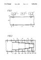
- FIG. 2 shows a second system for measuring the relative proportion of oil, water and gas in a fluid flow
- FIG. 3 shows the electronics used in the system of FIG. 2.
- a system for finding the dielectric constant of material within a tube comprises a voltage controlled oscillator (VCO) 2 built to generate a variable frequency RF (500 MHz to 1 GHz) or microwave (1 GHz to 20 GHz) electromagnetic signal.
- VCO voltage controlled oscillator
- This signal is supplied to electrodes 3 which launch it in the TE 11 mode along the tube 1.
- electrodes 3 which launch it in the TE 11 mode along the tube 1.
- a second pair of electrodes 4 which pick up the signal which is propagated along the pipe 1.
- the signal received by the electrodes 4 is measured by a detector 5 which supplies them to a controller 6.
- the controller 6 sweeps the voltage generated by the VCO 2 across a range of frequencies from the bottom of the range of the VCO 2 upwards, until a sudden increase in the signal received by the detector 5 shows that the cut-off frequency has been reached and the signal is propagating along the pipe 1. Once the controller 6 knows the cut-off frequency, the dielectric constant of the material within the pipe can easily be calculated because the radius of pipe 1 is known.
- the contents of the pipe 1 is crude oil, a mixture of oil, water and gas, three different fluids having different dielectric constants, it is not possible to deduce the relative proportions of the fluids without ambiguity from the average dielectric constant of the material within the pipe 1 alone. As a result, a system as simple as this cannot be used to calculate the relative quantities of oil, water and gas in a pipeline.
- the insertion loss, insertion phase, and time delay characteristics of the mixture of fluids within the pipe can be found.
- Water has both a dielectric constant and absorption coefficient strongly dependent on frequency. At low frequencies the relative dielectric constant of water is approximately 80, falling to less than 30 at 24 Ghz. Over a similar frequency band the absorption coefficient increases from less than 0.1 to 1.0 at 24 GHz.
- the properties of oil and gas are substantially invariant with frequency.
- the relative dielectric constant of oil is approximately 2.5 while its absorption coefficient is 0.001.
- the properties of gas are virtually indistinguishable from those of air.
- FIG. 2 a more practical system is shown comprising a conductive pipe 11 containing a plurality of smaller concentric pipes 12, 13, 14 and 15 all having different radii, the pipe 11 and all of the tubes 12 to 15 are conductive and circular in cross section.
- Each of the tubes 12 to 15 is supported from the wall of the pipe 11 by a respective set of vanes 12a to 15a.
- Each set of vanes 12a to 15a comprises six vanes equally spaced around the circumference of their respective tubes 12 to 15.
- a first set of transmission electrodes 16 arranged to transmit an applied electromagnetic signal down the pipe 11 in the TE 11 mode, and the tube 12 to 15 are arranged along the pipe in order of decreasing radius away from the electrodes 16.
- the largest radius tube 12 is nearest to the transmission electrodes 16, with the tube 13 with the next largest radius being placed next furthest from the transmission electrode 16, and so on, until the tube 15 with the smallest radius is arranged furthest from the transmission electrodes 16.
- Each of tubes 13 to 15 is arranged so that it projects slightly into the tube of next highest radius so that the two tubes overlap for a short distance.
- the tube of largest radius 12 inevitably overlaps completely with the pipe 11 because all the tubes of 12 to 15 are within the pipe 11.
- Each of the tubes 12 to 15 has an associated set of pickup electrodes 12b to 15b and a final set of pickup electrodes 17 are arranged within the pipe 11, between the tube of largest radius 12 and the transmission electrodes 16.
- the sets of vanes 12a to 15a divide up the annular regions between the wall of the pipe 11 and the outer surfaces of the tubes 12 to 15, into small enough portions that the cut-off frequency for transmission through these regions is very high, and also provide electrical contact between the pipe 11 and tubes 12 to 15.
- cut off frequencies for irregularly shaped areas like those defined by the vanes
- FIG. 3 the structure of the electrode sets 12b to 15b, 16 and 17, and their associated electronics, are shown.
- the transmission electrodes 16 comprise two electrodes 16a and 16b situated diametrically opposite one another on the pipe 11. All of the electrodes are insulated from contact with the conductive pipe 11 and tubes 12, 13, 14 and 15 by coaxial insulators. These insulating techniques are very well known and, for simplicity, are not illustrated in the figures.
- a plurality of crystal oscillators 18a to 18e are used, oscillating at frequencies of 0.6, 0.9, 1.2, 1.45 and 1.7 GHz respectively. All of the oscillators 18a to 18e are linked to a single pole multi-position switch 19 which can connect any of them to the output of the switch 19. Thus any one, and only one, of the signals from the crystal oscillators 18a to 18e can be produced as the output of the switch 19.
- This output signal passes through a coupler 20 to a 180° coupler 21.
- the two outputs from the 180° coupler 21 are connected to the two transmission electrodes 16a and 16b.
- the signals at the two transmission electrodes 16a and 16b are 180° out of phase versions of the signal generated by one of the crystal oscillators 18A to 18E, and this signal will be transmitted into the pipe 11 in the TE 11 mode.
- Each of the sets of receiver electrodes 12b to 15b and 17 comprise four electrodes arranged 90° apart around the circumference of their respective pipe or tube. Their angular position relative to the transmission electrodes 16 around the circumference of the pipe is not significant. In FIG. 3, only the set of electrodes 17a, 17b, 17c and 17d are shown with their associated electronics, but all of the other sets of receiver electrodes 12b to 15b are the same, and will have similar associated electronics.
- the four electrodes 17a to 17d are arranged 90° apart around the circumference of the pipe 11 so as to form two diametrically opposed pairs 17a, 17b and 17c, 17d.
- Each pair of receiver electrodes 17a, 17b and 17c, 17d are connected to two inputs of a respective 180° coupler 22, 23.
- the outputs from the 180° couplers 22 and 23 will comprise all the signals which are out of phase at the two electrodes of their respective pair 17a, 17b and 17c, 17d. All electrical signals which are in phase at the two electrodes of each pair will cancel.
- the signal from the 180° coupler 22 passes through an amplifier 24 and is converted to a d.c. voltage by a diode 25 and is amplified by a further amplifier 26 and is then digitized by analog to digital converter 27 which converts it into a digital optical signal in an optical fiber, leading to a controlling computer (not shown).
- the output from the 180° coupler 23 passes through a switch 28, which is also supplied with the output from the coupler 20, and the output from this switch then passes through an amplifier 29, diode 30, amplifier 31 and analog to digital converter 32, similarly to the output signal from the 180° coupler 22.
- the switch 28 is controlled by signals on a line 33 from the computer via a digital to analog converter 34, and can be switched to provide the computer with a sample, either of the signal across the electrode pair 17c, 17d, or a sample from the coupler 20 of the signal being transmitted by the transmitter electrodes 16a, 16b. Only the set of electrodes 17 will have a switch 28 connected in this way. This switch will be omitted on all the other sets of receive electrodes 12b to 15b.
- the position of the switch 19 is controlled by signals from the computer along the line 35.
- the computer connects each of oscillators 18a to 18e in turn to the transmit electrodes 16a and 16b using the switch 19 and checks the precise frequencies being generated by the oscillators 18a to 18e using the switch 28.
- the computer looks at the received signals in all the sets of receive electrodes 17, 12b, 13b, 14b and 15b, and measures the intensity of the microwave radiation received at each of the sets of receiver electrodes, and the relative time delay between transmitted signals and the received signals at the different sets of receiving electrodes.
- the average dielectric constant of the material within the pipe at a range of frequencies can be calculated. Since the conductivity of the pipe 11 and tubes 12 to 15 is known, the changes in the microwave energy in the pipe when it is propagating can be used to calculate the absorption of the material within the pipe 11 at these frequencies, and the phase insertion and time delays can be measured.
- the dielectric constant and absorption coefficient of a material form its complex permitivity, and the ratio between them is often referred to as the loss tangent. Having worked out both the dielectric constant and the absorption coefficient, the complex permitivity and loss tangent can be found if desired.
- the complex permitivity, or loss tangent, of water is variable with frequency and, as a result, by calculating the dielectric properties of material within the pipe 11 at two or more different frequencies, the relative quantities of gas, water and oil within the pipe 11 can be calculated.
- the TE 11 mode is the lowest frequency mode which can propagate in a tube
- the TM 01 mode is the next lowest frequency mode which can propagate in the tube, where frequencies between the frequencies of these two modes are used
- the cut off frequencies can be easily be distinguished. As a result, measurements made between these frequencies can be relied on, and due to the use of a plurality of tubes with different radii, there will always be plenty of data available at these frequencies in at least one of the tubes.
- the receive electrodes are arranged as two pairs of diametrically opposed electrodes with each pair being 90° apart from the other pair.
- the receive electrodes will pick up all modes and can be used to sense the relative energies in different modes at frequencies allowing multiple modes to propagate. These relative energies can be compared and, by doing this, the degree of inhomogeneity of the fluid within the pipe 11 can be calculated.
- This system is particularly suitable for under sea use for measuring the oil and gas content of crude oil.
Abstract
Description
Claims (6)
Applications Claiming Priority (2)
| Application Number | Priority Date | Filing Date | Title |
|---|---|---|---|
| GB919122210A GB9122210D0 (en) | 1991-10-18 | 1991-10-18 | Method for measurement of the gas and water content in oil |
| GB9122210.9 | 1991-10-18 |
Publications (1)
| Publication Number | Publication Date |
|---|---|
| US5351521A true US5351521A (en) | 1994-10-04 |
Family
ID=10703205
Family Applications (1)
| Application Number | Title | Priority Date | Filing Date |
|---|---|---|---|
| US07/961,167 Expired - Fee Related US5351521A (en) | 1991-10-18 | 1992-10-16 | Measurement of gas and water content in oil |
Country Status (3)
| Country | Link |
|---|---|
| US (1) | US5351521A (en) |
| GB (2) | GB9122210D0 (en) |
| NO (1) | NO924041L (en) |
Cited By (29)
| Publication number | Priority date | Publication date | Assignee | Title |
|---|---|---|---|---|
| US5485743A (en) * | 1994-09-23 | 1996-01-23 | Schlumberger Technology Corporation | Microwave device and method for measuring multiphase flows |
| US6192752B1 (en) * | 1995-08-04 | 2001-02-27 | Zevex, Inc. | Noninvasive electromagnetic fluid level sensor |
| US6466035B1 (en) * | 1998-06-03 | 2002-10-15 | Multi-Fluid Asa | Microwave fluid sensor and a method for using same |
| US6467358B1 (en) * | 1997-10-22 | 2002-10-22 | Japan National Oil Corp. | Method of measuring flow rates of respective fluids constituting multiphase fluid and flow meter for multiphase flow utilizing same |
| WO2003056316A1 (en) * | 2001-12-24 | 2003-07-10 | Promecon Prozess- Und Messtechnik Conrads Gmbh | Microwave measuring device for detecting the charge of a two-phase flow |
| US6658944B2 (en) * | 2000-03-09 | 2003-12-09 | Nest International N.V. | Simultaneous determination of multiphase flowrates and concentrations |
| US6707307B1 (en) | 2000-05-30 | 2004-03-16 | Esi Environmental Sensors Inc. | Fluid sensor |
| US6771080B2 (en) | 2001-12-24 | 2004-08-03 | Prozess - & Messtechnik Conrads Gmbh. | Microwave measuring device for defining the load of a two-phase flow |
| US20060091894A1 (en) * | 2001-08-24 | 2006-05-04 | Jean Buford R | Ultra-wide band pulse dispersion spectrometry method and apparatus providing multi-component composition analysis |
| US7114401B2 (en) | 2004-08-18 | 2006-10-03 | Baker Hughes Incorporated | Apparatus and methods for abrasive fluid flow meter |
| US20090088985A1 (en) * | 2006-05-02 | 2009-04-02 | Arnstein Wee | Method and Apparatus for Measuring the Conductivity of the Water Fraction of a Wet Gas |
| US20090126502A1 (en) * | 2006-05-05 | 2009-05-21 | Arnstein Wee | Method and Apparatus for Tomographic Multiphase Flow Measurements |
| US20090283257A1 (en) * | 2008-05-18 | 2009-11-19 | Bj Services Company | Radio and microwave treatment of oil wells |
| US20090306911A1 (en) * | 2008-06-05 | 2009-12-10 | Expro Meters, Inc. | Method and apparatus for making a water cut determination using a sequestered liquid-continuous stream |
| WO2010068118A1 (en) | 2008-12-12 | 2010-06-17 | Multi Phase Meters As | A method and apparatus for wet gas flow measurements and measurement of gas properties |
| WO2010068117A1 (en) | 2008-12-12 | 2010-06-17 | Multi Phase Meters As | A method and apparatus for measurement of composition and flow rates of a wet gas |
| US7805978B2 (en) | 2006-10-24 | 2010-10-05 | Zevex, Inc. | Method for making and using an air bubble detector |
| US20110079402A1 (en) * | 2009-10-02 | 2011-04-07 | Bj Services Company | Apparatus And Method For Directionally Disposing A Flexible Member In A Pressurized Conduit |
| US7987722B2 (en) | 2007-08-24 | 2011-08-02 | Zevex, Inc. | Ultrasonic air and fluid detector |
| US20120079830A1 (en) * | 2010-06-03 | 2012-04-05 | Rigoberto Rodriguez | Sensor communication system and machine having the same |
| US8539812B2 (en) | 2009-02-06 | 2013-09-24 | Zevek, Inc. | Air bubble detector |
| US8839856B2 (en) | 2011-04-15 | 2014-09-23 | Baker Hughes Incorporated | Electromagnetic wave treatment method and promoter |
| US20150293039A1 (en) * | 2014-04-09 | 2015-10-15 | Texas Instruments Incorporated | Material Detection and Analysis Using a Dielectric Waveguide |
| DE102016013220B3 (en) | 2016-11-04 | 2018-05-09 | PROMECON Prozeß- und Meßtechnik Conrads GmbH | Microwave measuring arrangement for determining the loading of a two-phase flow |
| US9970804B2 (en) | 2014-08-19 | 2018-05-15 | Emirates Innovations | Method and apparatus to detect contaminants in pressurized fluid flows |
| WO2019099341A1 (en) * | 2017-11-14 | 2019-05-23 | Saudi Arabian Oil Company | Measuring a water cut of hydrocarbon fluid in a production pipe |
| WO2019166870A1 (en) * | 2018-02-28 | 2019-09-06 | Saudi Arabian Oil Company | Detecting saturation levels of a sample core using electromagnetic waves |
| US11156079B2 (en) | 2018-12-18 | 2021-10-26 | Saudi Arabian Oil Company | Downhole tool for gas kick detection and liquid characterization using coaxial resonators |
| US11366071B2 (en) | 2020-03-04 | 2022-06-21 | Saudi Arabian Oil Company | Performing microwave measurements on samples under confining pressure using coaxial resonators |
Families Citing this family (4)
| Publication number | Priority date | Publication date | Assignee | Title |
|---|---|---|---|---|
| GB9502518D0 (en) * | 1995-02-09 | 1995-03-29 | Mms Space Systems Ltd | A method and apparatus for analysing the composition of a material |
| CA2384831C (en) * | 1999-09-17 | 2009-05-19 | Sik-Institut For Livsmedel Och Bioteknik Ab | Apparatus and method for detection of foreign bodies in products |
| CA2609826C (en) | 2005-05-27 | 2014-07-29 | Cidra Corporation | An apparatus and method for measuring a parameter of a multiphase flow |
| US7520667B2 (en) | 2006-05-11 | 2009-04-21 | John Bean Technologies Ab | Method and system for determining process parameters |
Citations (12)
| Publication number | Priority date | Publication date | Assignee | Title |
|---|---|---|---|---|
| US3498112A (en) * | 1968-04-30 | 1970-03-03 | Us Navy | Microwave system for determining water content in fuel oil |
| GB2110377A (en) * | 1981-11-05 | 1983-06-15 | Itt Ind Ltd | Detecting water in hydrocarbon liquids |
| US4423623A (en) * | 1981-08-24 | 1984-01-03 | Rockwell International Corporation | Microwave meter for fluid mixtures |
| US4429273A (en) * | 1981-03-20 | 1984-01-31 | Texaco Inc. | Oil-water monitor |
| EP0268399A2 (en) * | 1986-11-18 | 1988-05-25 | Atlantic Richfield Company | Microwave apparatus for measuring fluid mixtures |
| US4764718A (en) * | 1986-04-23 | 1988-08-16 | Chevron Research Company | Microwave oil saturation scanner |
| US4812739A (en) * | 1986-09-15 | 1989-03-14 | Swanson Claude V | Apparatus and method for using microwave radiation to measure water content of a fluid |
| US4820970A (en) * | 1986-09-15 | 1989-04-11 | Swanson Claude V | Apparatus and method for using microwave radiation to measure water content of a fluid |
| US4888547A (en) * | 1989-01-23 | 1989-12-19 | Rockwell International Corporation | Meter using a microwave bridge detector for measuring fluid mixtures |
| US5049823A (en) * | 1989-05-23 | 1991-09-17 | Institut Francais Du Petrole | Method and device for measuring the qualities of a multiphase fluid |
| US5103181A (en) * | 1988-10-05 | 1992-04-07 | Den Norske Oljeselskap A. S. | Composition monitor and monitoring process using impedance measurements |
| US5140271A (en) * | 1989-12-26 | 1992-08-18 | Texaco Inc. | Watercut means and method with debris reducing test cell |
-
1991
- 1991-10-18 GB GB919122210A patent/GB9122210D0/en active Pending
-
1992
- 1992-10-15 GB GB9221649A patent/GB2262807B/en not_active Expired - Fee Related
- 1992-10-16 US US07/961,167 patent/US5351521A/en not_active Expired - Fee Related
- 1992-10-19 NO NO92924041A patent/NO924041L/en unknown
Patent Citations (12)
| Publication number | Priority date | Publication date | Assignee | Title |
|---|---|---|---|---|
| US3498112A (en) * | 1968-04-30 | 1970-03-03 | Us Navy | Microwave system for determining water content in fuel oil |
| US4429273A (en) * | 1981-03-20 | 1984-01-31 | Texaco Inc. | Oil-water monitor |
| US4423623A (en) * | 1981-08-24 | 1984-01-03 | Rockwell International Corporation | Microwave meter for fluid mixtures |
| GB2110377A (en) * | 1981-11-05 | 1983-06-15 | Itt Ind Ltd | Detecting water in hydrocarbon liquids |
| US4764718A (en) * | 1986-04-23 | 1988-08-16 | Chevron Research Company | Microwave oil saturation scanner |
| US4812739A (en) * | 1986-09-15 | 1989-03-14 | Swanson Claude V | Apparatus and method for using microwave radiation to measure water content of a fluid |
| US4820970A (en) * | 1986-09-15 | 1989-04-11 | Swanson Claude V | Apparatus and method for using microwave radiation to measure water content of a fluid |
| EP0268399A2 (en) * | 1986-11-18 | 1988-05-25 | Atlantic Richfield Company | Microwave apparatus for measuring fluid mixtures |
| US5103181A (en) * | 1988-10-05 | 1992-04-07 | Den Norske Oljeselskap A. S. | Composition monitor and monitoring process using impedance measurements |
| US4888547A (en) * | 1989-01-23 | 1989-12-19 | Rockwell International Corporation | Meter using a microwave bridge detector for measuring fluid mixtures |
| US5049823A (en) * | 1989-05-23 | 1991-09-17 | Institut Francais Du Petrole | Method and device for measuring the qualities of a multiphase fluid |
| US5140271A (en) * | 1989-12-26 | 1992-08-18 | Texaco Inc. | Watercut means and method with debris reducing test cell |
Cited By (56)
| Publication number | Priority date | Publication date | Assignee | Title |
|---|---|---|---|---|
| US5485743A (en) * | 1994-09-23 | 1996-01-23 | Schlumberger Technology Corporation | Microwave device and method for measuring multiphase flows |
| US6192752B1 (en) * | 1995-08-04 | 2001-02-27 | Zevex, Inc. | Noninvasive electromagnetic fluid level sensor |
| US6467358B1 (en) * | 1997-10-22 | 2002-10-22 | Japan National Oil Corp. | Method of measuring flow rates of respective fluids constituting multiphase fluid and flow meter for multiphase flow utilizing same |
| US6466035B1 (en) * | 1998-06-03 | 2002-10-15 | Multi-Fluid Asa | Microwave fluid sensor and a method for using same |
| US6658944B2 (en) * | 2000-03-09 | 2003-12-09 | Nest International N.V. | Simultaneous determination of multiphase flowrates and concentrations |
| US6707307B1 (en) | 2000-05-30 | 2004-03-16 | Esi Environmental Sensors Inc. | Fluid sensor |
| US20060091894A1 (en) * | 2001-08-24 | 2006-05-04 | Jean Buford R | Ultra-wide band pulse dispersion spectrometry method and apparatus providing multi-component composition analysis |
| US7221169B2 (en) * | 2001-08-24 | 2007-05-22 | Rhino Analytics, L.P. | Ultra-wide band pulse dispersion spectrometry method and apparatus providing multi-component composition analysis |
| AU2002360901B2 (en) * | 2001-12-24 | 2007-10-25 | Promecon Prozess- Und Messtechnik Conrads Gmbh | Microwave measuring device for detecting the charge of two-phase flow |
| US6771080B2 (en) | 2001-12-24 | 2004-08-03 | Prozess - & Messtechnik Conrads Gmbh. | Microwave measuring device for defining the load of a two-phase flow |
| DE10164107C1 (en) * | 2001-12-24 | 2003-09-18 | Promecon Prozess & Messtechnik | Microwave measuring device for determining the loading of a two-phase flow |
| CN100429506C (en) * | 2001-12-24 | 2008-10-29 | 普罗梅康过程和测量技术康拉德斯有限责任公司 | Microwave measuring device for detecting the charge of a two-phase flow |
| WO2003056316A1 (en) * | 2001-12-24 | 2003-07-10 | Promecon Prozess- Und Messtechnik Conrads Gmbh | Microwave measuring device for detecting the charge of a two-phase flow |
| US7114401B2 (en) | 2004-08-18 | 2006-10-03 | Baker Hughes Incorporated | Apparatus and methods for abrasive fluid flow meter |
| US8224588B2 (en) | 2006-05-02 | 2012-07-17 | Multi Phase Meters As | Method and apparatus for measuring the conductivity of the water fraction of a wet gas |
| US20090088985A1 (en) * | 2006-05-02 | 2009-04-02 | Arnstein Wee | Method and Apparatus for Measuring the Conductivity of the Water Fraction of a Wet Gas |
| US20090126502A1 (en) * | 2006-05-05 | 2009-05-21 | Arnstein Wee | Method and Apparatus for Tomographic Multiphase Flow Measurements |
| US7624652B2 (en) | 2006-05-05 | 2009-12-01 | Multi Phase Meters As | Method and apparatus for tomographic multiphase flow measurements |
| US8910370B2 (en) | 2006-10-24 | 2014-12-16 | Zevex, Inc. | Method of making a universal bubble detector |
| US8225639B2 (en) | 2006-10-24 | 2012-07-24 | Zevex, Inc. | Universal air bubble detector |
| US7805978B2 (en) | 2006-10-24 | 2010-10-05 | Zevex, Inc. | Method for making and using an air bubble detector |
| US7818992B2 (en) | 2006-10-24 | 2010-10-26 | Zevex, Inc. | Universal air bubble detector |
| US7987722B2 (en) | 2007-08-24 | 2011-08-02 | Zevex, Inc. | Ultrasonic air and fluid detector |
| US20090283257A1 (en) * | 2008-05-18 | 2009-11-19 | Bj Services Company | Radio and microwave treatment of oil wells |
| US8286466B2 (en) * | 2008-06-05 | 2012-10-16 | Expro Meters, Inc. | Method and apparatus for making a water cut determination using a sequestered liquid-continuous stream |
| US20090306911A1 (en) * | 2008-06-05 | 2009-12-10 | Expro Meters, Inc. | Method and apparatus for making a water cut determination using a sequestered liquid-continuous stream |
| US9759592B2 (en) | 2008-12-12 | 2017-09-12 | Fmc Kongsberg Subsea As | Method and apparatus for wet gas flow measurements and measurement of gas properties |
| WO2010068117A1 (en) | 2008-12-12 | 2010-06-17 | Multi Phase Meters As | A method and apparatus for measurement of composition and flow rates of a wet gas |
| US8960016B2 (en) | 2008-12-12 | 2015-02-24 | Multi Phase Meters As | Method and apparatus for measurement of composition and flow rates of a wet gas |
| WO2010068118A1 (en) | 2008-12-12 | 2010-06-17 | Multi Phase Meters As | A method and apparatus for wet gas flow measurements and measurement of gas properties |
| US8646309B2 (en) | 2009-02-06 | 2014-02-11 | Zevek, Inc. | Air bubble detector |
| US8739601B2 (en) | 2009-02-06 | 2014-06-03 | Zevex, Inc. | Air bubble detector |
| US8539812B2 (en) | 2009-02-06 | 2013-09-24 | Zevek, Inc. | Air bubble detector |
| US20110079402A1 (en) * | 2009-10-02 | 2011-04-07 | Bj Services Company | Apparatus And Method For Directionally Disposing A Flexible Member In A Pressurized Conduit |
| US8528651B2 (en) | 2009-10-02 | 2013-09-10 | Baker Hughes Incorporated | Apparatus and method for directionally disposing a flexible member in a pressurized conduit |
| US8230934B2 (en) | 2009-10-02 | 2012-07-31 | Baker Hughes Incorporated | Apparatus and method for directionally disposing a flexible member in a pressurized conduit |
| US20120079830A1 (en) * | 2010-06-03 | 2012-04-05 | Rigoberto Rodriguez | Sensor communication system and machine having the same |
| US9303523B2 (en) * | 2010-06-03 | 2016-04-05 | Rolls-Royce North American Technologies, Inc. | Sensor communication system and machine having the same |
| US8839856B2 (en) | 2011-04-15 | 2014-09-23 | Baker Hughes Incorporated | Electromagnetic wave treatment method and promoter |
| US10018576B2 (en) * | 2014-04-09 | 2018-07-10 | Texas Instruments Incorporated | Material detection and analysis using a dielectric waveguide |
| US10416095B2 (en) * | 2014-04-09 | 2019-09-17 | Texas Instruments Incorporated | Material detection and analysis using a dielectric waveguide |
| US20150293039A1 (en) * | 2014-04-09 | 2015-10-15 | Texas Instruments Incorporated | Material Detection and Analysis Using a Dielectric Waveguide |
| US20180321165A1 (en) * | 2014-04-09 | 2018-11-08 | Texas Instruments Incorporated | Material detection and analysis using a dielectric waveguide |
| US9970804B2 (en) | 2014-08-19 | 2018-05-15 | Emirates Innovations | Method and apparatus to detect contaminants in pressurized fluid flows |
| WO2018082726A1 (en) | 2016-11-04 | 2018-05-11 | Promecon Prozess- Und Messtechnik Conrads Gmbh | Microwave measuring arrangement for determining the loading of a two-phase flow |
| US10697813B2 (en) * | 2016-11-04 | 2020-06-30 | Promecon Process Measurement Control Gmbh | Microwave measuring arrangement for determining the loading of a two-phase flow |
| DE102016013220B3 (en) | 2016-11-04 | 2018-05-09 | PROMECON Prozeß- und Meßtechnik Conrads GmbH | Microwave measuring arrangement for determining the loading of a two-phase flow |
| US10466182B2 (en) | 2017-11-14 | 2019-11-05 | Saudi Arabian Oil Company | Measuring a water cut of hydrocarbon fluid in a production pipe |
| WO2019099341A1 (en) * | 2017-11-14 | 2019-05-23 | Saudi Arabian Oil Company | Measuring a water cut of hydrocarbon fluid in a production pipe |
| US11293881B2 (en) * | 2017-11-14 | 2022-04-05 | Saudi Arabian Oil Company | Measuring a water cut of hydrocarbon fluid in a production pipe |
| US20220187220A1 (en) * | 2017-11-14 | 2022-06-16 | Saudi Arabian Oil Company | Measuring a water cut of hydrocarbon fluid in a production pipe |
| US11709141B2 (en) * | 2017-11-14 | 2023-07-25 | Saudi Arabian Oil Company | Measuring a water cut of hydrocarbon fluid in a production pipe |
| WO2019166870A1 (en) * | 2018-02-28 | 2019-09-06 | Saudi Arabian Oil Company | Detecting saturation levels of a sample core using electromagnetic waves |
| US10914688B2 (en) | 2018-02-28 | 2021-02-09 | Saudi Arabian Oil Company | Detecting saturation levels of a sample core using electromagnetic waves |
| US11156079B2 (en) | 2018-12-18 | 2021-10-26 | Saudi Arabian Oil Company | Downhole tool for gas kick detection and liquid characterization using coaxial resonators |
| US11366071B2 (en) | 2020-03-04 | 2022-06-21 | Saudi Arabian Oil Company | Performing microwave measurements on samples under confining pressure using coaxial resonators |
Also Published As
| Publication number | Publication date |
|---|---|
| GB9122210D0 (en) | 1991-11-27 |
| NO924041D0 (en) | 1992-10-19 |
| GB2262807A (en) | 1993-06-30 |
| GB9221649D0 (en) | 1992-11-25 |
| NO924041L (en) | 1993-04-19 |
| GB2262807B (en) | 1995-05-17 |
Similar Documents
| Publication | Publication Date | Title |
|---|---|---|
| US5351521A (en) | Measurement of gas and water content in oil | |
| US5101163A (en) | Oil/water measurement | |
| JP2523342B2 (en) | Device for measuring the concentration of one fluid contained in another fluid | |
| US5103181A (en) | Composition monitor and monitoring process using impedance measurements | |
| US5389883A (en) | Measurement of gas and water content in oil | |
| US4996490A (en) | Microwave apparatus and method for measuring fluid mixtures | |
| EP0495819B1 (en) | Improvements to oil/water measurement | |
| US20200309580A1 (en) | Electromagnetic multiphase flowmeter | |
| RU2327958C2 (en) | Device and process of level measurement by radiolocation | |
| EP0580787B1 (en) | Method for measuring water-oil mixtures with relatively high gas content | |
| JP2920197B2 (en) | Oil flow analyzer and method | |
| RU2536184C1 (en) | Concentration meter | |
| RU2761954C1 (en) | Method for measuring the physical properties of a dielectric liquid | |
| RU2073852C1 (en) | Shf-apparatus for measuring moisture content in petroleum and petroleum products | |
| RU2762058C1 (en) | Device for measuring the physical properties of a dielectric liquid | |
| NO346797B1 (en) | In-line flowmeter sensor device, in-line flowmeter and method for real-time monitoring of a volumetric ratio of fluid | |
| Guo et al. | Transmission media for microwave level gauging systems | |
| JPH0510611B2 (en) | ||
| KR0181736B1 (en) | Apparatus and method for measuring the optimum moisture content in oil flow | |
| Bøifot | Compact broadband TE01-mode generator |
Legal Events
| Date | Code | Title | Description |
|---|---|---|---|
| AS | Assignment |
Owner name: GEC-MARCONI LIMITED, UNITED KINGDOM Free format text: ASSIGNMENT OF ASSIGNORS INTEREST.;ASSIGNOR:CRACKNELL, DAVID J.;REEL/FRAME:006358/0348 Effective date: 19921126 |
|
| AS | Assignment |
Owner name: ABB SEATEC LIMITED, UNITED KINGDOM Free format text: ASSIGNMENT OF ASSIGNORS INTEREST;ASSIGNOR:GEC-MARCONI LIMITED;REEL/FRAME:007838/0917 Effective date: 19960209 |
|
| AS | Assignment |
Owner name: ASEA BROWN BOVERI AS, NORWAY Free format text: ASSIGNMENT OF ASSIGNORS INTEREST;ASSIGNOR:ABB SEATEC LIMITED;REEL/FRAME:007945/0087 Effective date: 19960422 |
|
| FPAY | Fee payment |
Year of fee payment: 4 |
|
| REMI | Maintenance fee reminder mailed | ||
| LAPS | Lapse for failure to pay maintenance fees | ||
| STCH | Information on status: patent discontinuation |
Free format text: PATENT EXPIRED DUE TO NONPAYMENT OF MAINTENANCE FEES UNDER 37 CFR 1.362 |
|
| FP | Lapsed due to failure to pay maintenance fee |
Effective date: 20021004 |