US5359513A - Method and system for detection of interval change in temporally sequential chest images - Google Patents
Method and system for detection of interval change in temporally sequential chest images Download PDFInfo
- Publication number
- US5359513A US5359513A US07/981,471 US98147192A US5359513A US 5359513 A US5359513 A US 5359513A US 98147192 A US98147192 A US 98147192A US 5359513 A US5359513 A US 5359513A
- Authority
- US
- United States
- Prior art keywords
- images
- image
- roi
- correlation
- template
- Prior art date
- Legal status (The legal status is an assumption and is not a legal conclusion. Google has not performed a legal analysis and makes no representation as to the accuracy of the status listed.)
- Expired - Lifetime
Links
- 238000000034 method Methods 0.000 title claims abstract description 115
- 230000008859 change Effects 0.000 title description 15
- 238000001514 detection method Methods 0.000 title description 9
- 238000004458 analytical method Methods 0.000 claims abstract description 14
- 238000012545 processing Methods 0.000 claims description 28
- 238000013507 mapping Methods 0.000 claims description 23
- 230000002159 abnormal effect Effects 0.000 claims description 3
- 230000000875 corresponding effect Effects 0.000 claims 8
- 230000002596 correlated effect Effects 0.000 claims 2
- 230000008569 process Effects 0.000 abstract description 11
- 210000000038 chest Anatomy 0.000 description 39
- 210000004072 lung Anatomy 0.000 description 21
- 230000015654 memory Effects 0.000 description 15
- 239000011159 matrix material Substances 0.000 description 13
- 210000001370 mediastinum Anatomy 0.000 description 10
- 238000012937 correction Methods 0.000 description 8
- 238000010191 image analysis Methods 0.000 description 8
- 230000005856 abnormality Effects 0.000 description 7
- 238000004364 calculation method Methods 0.000 description 6
- 230000000694 effects Effects 0.000 description 6
- 230000006870 function Effects 0.000 description 6
- 230000002123 temporal effect Effects 0.000 description 6
- 238000007781 pre-processing Methods 0.000 description 5
- 208000006029 Cardiomegaly Diseases 0.000 description 4
- 238000004195 computer-aided diagnosis Methods 0.000 description 3
- 201000010099 disease Diseases 0.000 description 3
- 208000037265 diseases, disorders, signs and symptoms Diseases 0.000 description 3
- 230000003902 lesion Effects 0.000 description 3
- 238000012805 post-processing Methods 0.000 description 3
- 239000007787 solid Substances 0.000 description 3
- 230000009466 transformation Effects 0.000 description 3
- 206010028980 Neoplasm Diseases 0.000 description 2
- 206010056342 Pulmonary mass Diseases 0.000 description 2
- 210000003484 anatomy Anatomy 0.000 description 2
- 238000011976 chest X-ray Methods 0.000 description 2
- 238000007405 data analysis Methods 0.000 description 2
- 238000011161 development Methods 0.000 description 2
- 238000013213 extrapolation Methods 0.000 description 2
- 238000001914 filtration Methods 0.000 description 2
- 238000010606 normalization Methods 0.000 description 2
- 230000007170 pathology Effects 0.000 description 2
- 238000011524 similarity measure Methods 0.000 description 2
- 206010019280 Heart failures Diseases 0.000 description 1
- 208000019693 Lung disease Diseases 0.000 description 1
- OAICVXFJPJFONN-UHFFFAOYSA-N Phosphorus Chemical compound [P] OAICVXFJPJFONN-UHFFFAOYSA-N 0.000 description 1
- 210000000988 bone and bone Anatomy 0.000 description 1
- 208000003362 bronchogenic carcinoma Diseases 0.000 description 1
- 230000000747 cardiac effect Effects 0.000 description 1
- 230000010351 cardiac pulsation Effects 0.000 description 1
- 230000001186 cumulative effect Effects 0.000 description 1
- 230000001419 dependent effect Effects 0.000 description 1
- 238000003745 diagnosis Methods 0.000 description 1
- 230000003292 diminished effect Effects 0.000 description 1
- 230000002708 enhancing effect Effects 0.000 description 1
- 238000002474 experimental method Methods 0.000 description 1
- 230000036541 health Effects 0.000 description 1
- 238000012986 modification Methods 0.000 description 1
- 230000004048 modification Effects 0.000 description 1
- 230000036285 pathological change Effects 0.000 description 1
- 231100000915 pathological change Toxicity 0.000 description 1
- 238000003672 processing method Methods 0.000 description 1
- 230000029058 respiratory gaseous exchange Effects 0.000 description 1
- 238000005549 size reduction Methods 0.000 description 1
Images


Classifications
-
- G06T3/153—
-
- G—PHYSICS
- G06—COMPUTING; CALCULATING OR COUNTING
- G06T—IMAGE DATA PROCESSING OR GENERATION, IN GENERAL
- G06T5/00—Image enhancement or restoration
- G06T5/50—Image enhancement or restoration by the use of more than one image, e.g. averaging, subtraction
-
- G—PHYSICS
- G06—COMPUTING; CALCULATING OR COUNTING
- G06T—IMAGE DATA PROCESSING OR GENERATION, IN GENERAL
- G06T2207/00—Indexing scheme for image analysis or image enhancement
- G06T2207/20—Special algorithmic details
- G06T2207/20212—Image combination
- G06T2207/20224—Image subtraction
-
- Y—GENERAL TAGGING OF NEW TECHNOLOGICAL DEVELOPMENTS; GENERAL TAGGING OF CROSS-SECTIONAL TECHNOLOGIES SPANNING OVER SEVERAL SECTIONS OF THE IPC; TECHNICAL SUBJECTS COVERED BY FORMER USPC CROSS-REFERENCE ART COLLECTIONS [XRACs] AND DIGESTS
- Y10—TECHNICAL SUBJECTS COVERED BY FORMER USPC
- Y10S—TECHNICAL SUBJECTS COVERED BY FORMER USPC CROSS-REFERENCE ART COLLECTIONS [XRACs] AND DIGESTS
- Y10S128/00—Surgery
- Y10S128/92—Computer assisted medical diagnostics
- Y10S128/922—Computer assisted medical diagnostics including image analysis
Definitions
- the present invention relates to the field of computerized analysis of digitized medical images such as chest X-ray images, for example, which is used for the enhancement of subtle interval changes occurring between a pair of images corresponding to a given patient, one of which has been produced prior to the other so that changes between the two images can be detected using digital image processing techniques.
- interval change is defined here as a pathological change which has occurred after the previous examination and before the current examination.
- FIG. 12 illustrates various sources of misregistration in pairs of temporally sequential P-A chest images, which have been determined by studying more than 40 pairs of images. Most pairs have misregistration due to a combination of these sources.
- a related object is to provide a computerized method and apparatus for performing image registration processing of a pair of temporally sequential chest images by performing nonlinear warping of one of the images and then performing a subtraction process between the warped image and the other image.
- a further object is to provide a computerized method and apparatus for performing image registration and subtraction where nonlinear warping of one of a pair of temporally sequential images of a given patient is based on a local matching technique applied to a number of small regions of interest (ROIs) in the two images.
- ROIs regions of interest
- a still further object of the present invention is to provide a computerized method and apparatus for enhancement and detection of lung disease which uses an image registration technique for matching a pair of temporally sequential chest images and then performing a subtraction process between the two images where the image registration technique involves the selection of a number of small ROIs on the images based on data obtained by image analysis of the two chest images.
- Yet another object of the invention is to provide a method and apparatus for the detection of interval changes between a pair of temporally sequential medical images using a nonlinear warping technique in order to perform image registration between the two images based on the determination of mapping shift values, which values represent the result of a local matching technique applied to a number of small ROIs in the two temporally sequential images.
- Another object of the invention is to provide a method and apparatus for performing a subtraction between a pair of digitized medical images in order to enhance and detect possible abnormal regions on the images where the two images are matched with each other on the basis of a nonlinear warping technique which is applied to one of the two images in order to allow subtraction of the digitized images, such that the nonlinear warping technique is performed by using a mapping of shift values between corresponding locations on the two images and the mapping of the shift values is based on two-dimensional polynomial functions which are fitted to the shift values.
- Another object of the invention is to provide a method and apparatus for performing image registration and subtraction between a pair of temporally sequential images which employs a weighted fitting technique for fitting polynomial functions to a plurality of shift values where the weighting factors determine the extent of contribution of the polynomial fitting for each of the shift values.
- Another object of the present invention is to provide a method and apparatus for implementing a computerized scheme which enables the enhancement and detection of abnormalities in a pair of temporally sequential medical images which uses a weighted fitting technique for fitting polynomial functions to a plurality of shift values representing the amount of misregistration between corresponding locations in the two images where the fitting technique is a weighted technique having weighting factors determined on the basis of information related to a local matching process and/or the results of image data analysis.
- the present invention involves a computerized scheme whereby a pair of chest images are produced using a known X-ray technique which images are then digitized and subjected to processing by a digital computer.
- the technique includes the registration of the two images in order for corresponding locations in the images to be aligned so that subtraction processing can then be performed. This subtraction of the two images will enhance subtle changes between the two images which may be indications of abnormality, such as interstitial disease, tumors, etc.
- a nonlinear warping is applied to one of the images in order to provide the required alignment between corresponding locations in the two images.
- the nonlinear warping scheme is based on a local matching technique of a number of small regions of interest (ROIs) selected on the basis of detected information concerning the anatomic structures of the chest images.
- the local matching technique is represented by a mapping of the shift values between the corresponding locations in the two images, where the mapping of shift values is subjected to a curve fitting technique which uses weighting factors based on the amount of local matching, or the results of image data analysis performed on the ROIs.
- FIG. 1A shows the overall scheme of image registration and subtraction processing according to the present invention
- FIG. 1B shows the basic steps according to the invention from the digitization of the two chest images to the output of the subtraction image
- FIG. 1C illustrates the method for performing selection of the ROIs
- FIG. 1D represents the individual steps performed for the curve fitting technique for application to the mapped shift values
- FIG. 2 shows the overlying search areas and templates used with the first and second digitized images
- FIG. 3 shows a pair of graphs illustrating the relationships between the template size and the average cross-correlation value and processing time for performing local matching
- FIG. 4 illustrates the various shapes of template and search area ROIs which can be used for performing the local matching technique
- FIG. 5 illustrates a general principle of the local matching technique using a cross-correlation method
- FIG. 6 shows schematic illustrations of the results of shift mapping between corresponding locations of the two images
- FIG. 7 illustrates the general principle of the weighted fitting of the shift mapping results
- FIG. 8 illustrates shift-maps of the distribution of fitted shift values ⁇ x and ⁇ y, generated from the shiftmaps shown in FIG. 6 using two-dimensional nth-order polynomials;
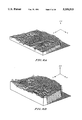
- FIG. 9 shows the concept of nonlinear warping of the x,y coordinates in accordance with the technique of the present invention.
- FIG. 10 illustrates a computerized printout of the grid pattern corresponding to the image to be warped such as shown in FIG. 9;
- FIG. 11A illustrates the overall system used to implement the technique of the present invention
- FIG. 11B illustrates the use of weighting factors with the curve fitting calculator in the system of the invention
- FIG. 12 illustrates the various causes of misregistration between a pair of temporally sequential chest images
- FIG. 13A illustrates a chest radiograph image having a focal air space infiltrate shown in the patient's right upper lobe
- FIG. 13B illustrates a chest radiograph image corresponding to that shown in FIG. 13A taken three months earlier, without the appearance of the air space infiltrate;
- FIG. 13C represents the difference image obtained by subtraction processing between the images of FIGS. 13A and 13B;
- FIG. 14A shows a radiographic image of a patient's chest X-ray
- FIG. 14B shows a second image of the lungs of the same patient shown in FIG. 14A;
- FIG. 14C shows the warped image of a FIG. 14A
- FIG. 14D shows the difference image produced between the warped image of FIG. 14C and the second image shown in FIG. 14B;
- FIG. 15A shows a chest radiograph image having multiple nodules, one of which in the left upper lobe has developed a cavity therein, as shown by the light regions representative of opacities within the lungs;
- FIG. 15B shows the image of FIG. 15A taken two years earlier and showing the existence of multiple nodules less prominent than those shown in FIG. 15A;
- FIG. 15C illustrates a difference image produced between the images of FIGS. 15A and 15B;
- FIG. 16A illustrates the existence of a cardiomegaly
- FIG. 16B illustrates a chest radiograph image of the same patient's lungs with a cardiomegaly as shown in FIG. 16A and taken two years earlier;
- FIG. 16C illustrates a difference image obtained by the subtraction of images 16A and 16B using the technique in accordance with the present invention
- FIG. 17 illustrates the effects caused by various artifacts in the subtraction image employing global shift registration without the use of the present invention, where the effects are quite prominent due to a mismatch of bones and vessels.
- the method includes the digitization of a pair of first and second images (steps 10, 20), image registration (step 40) and then subtraction (step 50) of the images.
- steps 10, 20 image registration
- step 40 image registration
- step 50 subtraction
- digital chest images obtained directly with a storage phosphor detector system or a CCD detector system can be used.
- the steps 30, 60 shown in italics are preferable but are not necessary for carrying out the method of the invention.
- the subtraction image is output in step 70.
- FIG. 1B illustrates in more detail the overall scheme for performing interval change enhancement between a pair of temporally sequential chest images, including the steps of digitization (steps 10, 20) of a pair of chest radiograph images, selection of a number of small regions of interest (ROIs) (steps 41, 42) and then image registration using the selected ROIs.
- Image registration includes the use of a local matching technique (step 43) which is applied to each pair of corresponding ROIs in the two images, and the mapping of shift values (step 44) representative of the amount of local matching between each corresponding pair of ROIs.
- a curve fitting technique (step 45) is applied to the mapped shift values, and nonlinear warping (step 46) of one of the two images is performed based on the results of the curve fitting analysis.
- subtraction step 50 of the warped and unwarped images is performed for each pair of corresponding ROIs.
- the subtraction image is then output (step 70) to enable viewing by a radiologist who can then compare the results obtained by the subtraction processing with the results obtained by side-by-side viewing of the temporally sequential images.
- Steps 30, 60 are preferred but not essential to the invention.
- FIG. 1C illustrates the process of selection of the ROIs (steps 41, 42) in the two digitized images, which is based on the analysis of the anatomic structures (step 11, i.e., ribcage edge location, etc.) of the chest images and a determination of the distance between the centers of the ROIs (step 14) and a determination of the locations of these centers (step 13).
- the size and shape of the ROIs are also selected (step 15).
- the location of the ROIs (step 47) is thus determined.
- Step 12 is also an optional step which is not required for the invention.
- the shift mapping technique used with the local mapping scheme according to the present invention is shown in FIG. 1D.
- a shift map is determined (step 80) and the weighting factors used in the weighted curve fitting technique are determined (step 84) after the analysis of similarities between the template ROIs and the search area ROIs and based on the analysis of the anatomic structures and the pixel value distribution in the chest images.
- interpolation/extrapolation techniques step 86
- a fitted shift map is then produced (step 87).
- the steps 81-84 are optional.
- the local matching technique involves the selection of ROIs in the two images, i.e., the template ROI image and the search area ROI image.
- the template ROI is moved within the search area ROI to determine the best match of the template ROI relative to the search area ROI of the other image.
- the search area ROIs and the template ROIs are automatically selected by the computer, as shown in FIG. 2.
- the large number of dotted areas represent the centers of the ROIs in each image.
- the basic concept of the image registration technique used in the present invention employs nonlinear distortion (warping) of one of the images in order to obtain improved registration between the two images so that subtraction processing can be carried out.
- the nonlinear warping is performed based on local matchings of a number of small regions of interest (ROIs) at corresponding locations in the two images.
- ROIs small regions of interest
- a small template ROI is selected in one image.
- a search area ROI is selected where a subregion which matches the template subimage will be searched for within the search area.
- the search area can be the whole image area, but it is preferable to select a search area ROI which is slightly larger than the template ROI approximately at the corresponding location in terms of anatomic structures, in order to obtain higher accuracy and shorter processing time.
- Location of lung areas can be determined by known image analysis schemes which can detect specific anatomic structures such as ribcage edges, location of the diaphragm, heart area, and mediastinum. These methods are described in U.S. Pat. No. 4,851,984, for example.
- Locations of the centers of templates and search areas can also be determined based on the above-mentioned image analysis schemes.
- a center of a search area should be located in approximately the same position in terms of anatomy as that of the corresponding template.
- Centers of template ROIs and those of search area ROIs can be selected independently using the above mentioned image analysis techniques for each image separately.
- FIG. 2 illustrates that the centers of the templates are selected in the ribcage area as are the centers of the corresponding search areas obtained by shifting the centers of templates based on the relative locations of the crossing point of the midline and the topline of the lungs.
- the size of template ROIs is preferably 5-50 mm in diameter, and more preferably, 15-40 mm in diameter.
- the size selected will also depend on the particular local matching algorithm used. As shown in FIG. 3, if the size of the templates ROIs is too small, the accuracy of matching will be low. On the other hand, if the size is too large, processing time will be long. Also, if the size is too large, the matching for the entire ROI may not be consistent with the matching for the center part of the ROI. In other words, if a single large ROI is used for each of the template and search area ROIs, the structure within the ROI can change because of the large area being analyzed.
- the size of the search area ROIs should be larger than the corresponding template ROIs, preferably 10-40 millimeters larger in diameter.
- the size of the search area ROIs also depends upon the size of the temporal changes to be detected. If the size of the search area ROIs is too small, the accuracy of matching will be low, while if the size is too large, the corresponding regions will be matched, but even real temporal changes in pathology, such as change in heart size, change in diaphragm, etc. will be diminished.
- the distance between the centers of the two regions should be preferably 5-30 millimeters. If this distance is too small, however, the processing time will be relatively long, while if the distance is too large the accuracy of warping may be low.
- the shape of the template and search area ROIs can be any one of a number of variations.
- the ROIs do not have to be located all over the ribcage area.
- extremely low density area in the mediastinum region may have a lower number of ROIs than the lung area, since it is less important in diagnosis. It is possible to set the longer distance between centers in the mediastinum region, or not to select ROIs in the low density area in the center of the mediastinum region.
- the mediastinum is the white area shown near the center of the chest image due to the spine and related anatomical structures. The density of this area will accordingly be low and therefore not much information will be obtained from this region and fewer ROIs will be selected here.
- the local matching technique of the invention is used to determine the subregion in a search area ROI which produces the "best” match with the corresponding template ROI.
- the "best” match means that the similarity between the image data in the determined subregion and those of the template is higher than any other possible subregions in the search area. Any existing algorithms to evaluate the similarities between two subimages and determine the "best” match can be used for local matching.
- a second manner by which the local matching technique can be performed according to the present invention is by using a least square difference method.
- this method that subregion which minimizes the summation of the squares of the difference values between the corresponding locations in the two images is determined, based on the following equation: ##EQU2## This equation derives results which are identical to those obtained using the normalized cross-correlation method.
- a third method for performing local matching between the locations of the two images according to the invention is by a least difference method.
- the subregion which minimizes the summation of the absolute value of the difference between each pair of corresponding locations (pixels) in the two images is determined using the following equation: ##EQU3##
- a fourth method of local matching according to the invention uses a Fourier transform phase correlation technique, where the subregion which maximizes the correlation between the phase factors of Fourier transforms of two subimages is determined with the following equation: ##EQU4## where F(u,v) is the Fourier transform of A(i,j)
- G(u,v) is the Fourier transform of B x'y' (i,j)
- F -1 ⁇ ⁇ is the inverse Fourier transform.
- the normalized cross-correlation, least square difference and Fourier transform phase-correlation methods provide the best results in terms of accuracy of matching.
- Examples of the parameters which can be successfully used with the above local matching technique are as follows: a pixel size equal to 0.7 mm, a template ROI having a size equal to 22.4 mm ⁇ 22.4 mm (32 ⁇ 32 matrix size), a search area size equal to 44.8 mm ⁇ 44.8 mm (64 ⁇ 64 matrix size), distance between the centers equal to 7.0 mm (10 pixels), using a normalized cross-correlation method.
- a local matching algorithm does not have to be performed on a pixel by pixel basis, i.e., it is possible to skip pixels in both the template ROI and search area ROI in order to save processing time.
- the parameters which can be successfully used with the above local matching technique are as follows: a pixel size equal to 0.7 mm, a template ROI having a size equal to 22.4 mm ⁇ 22.4 mm (32 ⁇ 32 matrix size), a search area size equal to 44.8 mm ⁇ 44.8 mm (64 ⁇ 64 matrix size), distance between the centers equal to 7.0 mm (10 pixels), using a normalized cross-correlation method. Calculations were performed on a 16 ⁇ 16 matrix for each template, by skipping one out of every two pixels. The resulting registration was comparable to what was obtained without skipping pixels, and the processing time was reduced to one-fourth that without skipping pixels.
- One of the above local matching techniques can be performed in two or more steps for each center of the template. For example, for the first step, a relatively large template ROI and a relatively large search area ROI can be selected, and then a coarse-search local matching method can be employed by skipping pixels to find an approximate location of center of the "best" match subregion. Next, a small template ROI and a small search area ROI near the approximate "best" match location are selected to perform a fine-search for local matching in the second step. This method can improve accuracy and also can save processing time, if proper processing parameters are selected.
- Examples of the parameters used for the above method are as follows: a pixel size equal to 0.7 mm, a template ROI having the dimensions 44.8 mm ⁇ 44.8 mm (64 ⁇ 64 matrix size) for the first step, and 11.2 mm ⁇ 11.2 mm (16 ⁇ 16 matrix size) for the second step, a search area size equal to 67.2 mm ⁇ 67.2 mm (96 ⁇ 96 matrix size) for the first step, and 19.6 mm ⁇ 19.6 mm (28 ⁇ 28 matrix size) for the second step, a distance between the centers equal to 7.0 mm (10 pixels), and using a normalized cross-correlation method.
- For the first step calculations were performed on a 16 ⁇ 16 matrix for each template, by skipping one out of every four pixels. The resulting registration was comparable to the results described above and the processing time was reduced to one-third that without skipping pixels.
- the cartesian coordinate location of the center of the "best" match subregion can be found, which is indicated by (x',y') in the search area.
- the distance in the x and y directions between (x',y') and the location of the center of the template (x,y) is called shift value ⁇ x and ⁇ y, respectively, as illustrated in FIG. 5.
- the distribution of those shift values over the important area of the chest image which is obtained from a number of pairs of template and search area is the critical information which is necessary in order to obtain the proper geometric warping of the (x,y) coordinates prior to subtraction of the images.
- FIG. 6 shows examples of shift-maps showing the distribution of shift values ⁇ x and ⁇ y, obtained by local matching using a normalized cross-correlation method.
- the pixel size used was 0.7 mm
- the template shape was selected to be square with a size of 22.4 ⁇ 22.4 mm (32 ⁇ 32 matrix size)
- the search area size was selected to be 44.8 ⁇ 44.8 mm (64 ⁇ 64 matrix size)
- the distance between the centers was selected as 7.0 mm (10 pixels).
- FIG. 6 shows some singular points--unusually large or small shift values--in the distribution of ⁇ x and ⁇ y, despite the relatively smooth surface in most regions.
- weighted fittings using two-dimensional nth order polynomials are preferable.
- a local matching method evaluates similarities between a template ROI and a subregion selected in a search area ROI in order to determine a "best" match subregion.
- Any local matching method has a measure for similarity, such as the normalized cross-correlation value in the cross-correlation method.
- the larger the normalized cross-correlation value the better the matching which is produced for the template, as shown by equation (1) above. Therefore, the weighting factors can be determined based on the similarity measure produced by the "best" match subregion for each template, so that shift values with good matching having a large similarity measure are provided with large weighting factors.
- a lookup table can be generated which defines the relationship between weighting factors and the normalized cross-correlation values. Weighting factors for all shift values in a shift-map can therefore be provided in accordance with the lookup table, as illustrated in FIG. 7.
- P and Q may typically have a value equal to 0.65 when Q has a value equal to 0.9.
- the lung areas contain more important diagnostic information in comparison to other regions, large weighting factors can be provided for fitting of the shift values obtained with templates in the lung area.
- Location of lung areas can be determined by image analysis schemes such as disclosed in U.S. Pat. Nos. 4,851,984 and 5,072,384 for the detection of specific anatomic structures such as ribcage edges, diaphragm, heart area, and mediastinum.
- the weighting factor is set to be "zero" under the diaphragm and in the middle of the mediastinum, and will be "one" in the rest of the region.
- this method is used for the detection of interval changes in specific regions in chest images, those specific regions can be provided with large weighting factors.
- the density distribution of the various locations around the mediastinum, heart and diaphragm will frequently be very low and therefore little information will obtained from these regions.
- the contributions from these areas will accordingly be ignored, and the weighting factors of these regions set at 0.
- the maximum and minimum pixel values for these regions will indicate their locations.
- About 10% of the low pixel values will therefore be ignored since these regions offer little, if any, diagnostic information to the radiologist, due to the low density of these regions.
- the weighting factors are dependent on the locations of the anatomical features since outside the ribcage edges there is little diagnostic information and therefore the correlation, i.e., matching, outside these areas are also ignored.
- the weighting factor is set at zero between the minimum pixel value and the value ⁇ minimum+0.1 ⁇ (maximum - minimum) ⁇ , and is 1 for all larger pixel values. Weighting factors can be determined based on a combination of these three types of analysis.
- FIG. 8 shows shift-maps illustrating the distribution of fitted shift values ⁇ x and ⁇ y, generated from the shift-maps shown in FIG. 6.
- the shift values for the points outside the ribcage were determined by a linear extrapolation method.
- the nonlinear transformation of the (x,y) coordinates can be determined.
- the obtained pairs of ( ⁇ x, ⁇ y) refers to the fact that a point (x,y) in one image corresponds to the point (x+ ⁇ x, y+ ⁇ y) in the other image, as shown in FIGS. 9 and 10.
- FIG. 9 shows an illustration of nonlinear warping according to the present invention.
- the dotted grid pattern on the left indicates the cartesian coordinates (x,y) in one image and the solid grid pattern overlapping the dotted grid pattern indicates the corresponding points (x+ ⁇ x, y+ ⁇ y) in the other image.
- the solid grid pattern on the left should be transformed to the solid grid pattern shown on the right in order to obtain proper registration.
- the equations below show the general form of this nonlinear transformation. ##EQU7##
- FIG. 10 shows an example of the grid pattern of (x+ ⁇ x, y+ ⁇ y) produced by the sets of shift values ⁇ x and ⁇ y in FIG. 8.
- the coefficients a ii and b ij in the above equations do not have to be determined, since a subtraction image can be created by subtracting the pixel value of the point (x,y) in one image from the pixel value of the corresponding point (x+ ⁇ x, y+ ⁇ y) in the other image using calculated values of ⁇ x and ⁇ y, and then providing the subtraction value as the pixel value of a point (x,y) in the subtraction image. Since fitted shift values ⁇ x and ⁇ y are real numbers, the point (x+ ⁇ x, y+ ⁇ y) can be located between pixels in a digital image. In that case, the pixel value can be substituted with an interpolated pixel value by using the adjacent pixels. Any existing interpolation methods can be used for this purpose, such as nearest neighbor interpolation, linear interpolation, spline interpolation, etc.
- digital image input device 100 supplies the same digitized image to each of image memories 110, 120.
- Each of these memories has a first output which is received by ROI location selector 130.
- Image memory 110 has a second output which is received by warped image memory 200.
- Image memory 120 has a second output which is received by subtraction calculator 210.
- the ROI location selector outputs the result of the selection of the ROI locations to ROI image memory 140 and shift-map generator 160. Local matching is performed in calculator 150 which then outputs the result of local matching to the generator 160.
- Shift-map generator 160 outputs a result of the shift-map calculation to shift-map memory 170, wherein the mapping of values between the two images is stored.
- a curve fitting calculator 180 receives the output of memory 170 and performs the curve fitting function described above. This result is stored in memory 190 which then outputs to memory 200. The warped image stored in memory 200 is then received by the subtraction calculator device 210 for performing the subtraction process. The result of this process is stored in memory 220 and subsequently displayed to an output display device 230 for viewing by the radiologist.
- FIG. 11b shows the overall system according to the invention with the use of weighted factors for use in performing the curve fitting technique.
- a pixel value distribution analyzer 135 is connected in series between the memories 110, 120 and the ROI location selector 130.
- a lung area detector 125 is serially connected between each of the memories 110, 120 and the selector 130.
- An additional memory 155 is provided for storing the results of the local matching calculations performed in calculator 150. These results are then output to weighting factors generator 175, for generation of the appropriate weighting factors to be applied to the selected ROIs.
- these weighting factors are output to weighted curve fitting calculator 185 wherein the above described process of performing any order polynomial fitting can be performed.
- the remaining elements of FIG. 11B are identical to those shown in FIG. 11A and therefore will not be described.
- FIGS. 13A-17 The results of the inventive scheme are illustrated in FIGS. 13A-17.
- FIGS. 13A and 13B an air space infiltrate which was not present in the image of FIG. 13B, the image two years later showed the existence of the infiltrate quite clearly.
- FIGS. 14A-D illustrate an example of warped and unwarped images and a substraction image formed between the two images (lower right).
- FIGS. 15A and 15B illustrate a pair of images for a particular patient where the earlier image, FIG. 15B, was taken two years earlier than that of FIG. 15A.
- the difference image (subtraction) is shown in FIG. 15C.
- FIG. 16A shows the existence of cardiomegaly, i.e., enlargement of the heart, and the same image taken two years earlier, FIG. 16B.
- the subtraction image clearly shows in FIG. 16C the difference in amount of cardiomegaly and also the accompanying profusions (as indicated below the image) which resulted from the cardiac failure associated with the enlargement.
- FIG. 17 shows a difference image which was produced with the global shift of one of the pair of images. The existence of various artifacts in this figure is prominent due to the mismatch of the anatomical features.
- FIGS. 14A-14D show an example of the digital image subtraction processing used in this invention, using two temporally sequential original images where one of the original images is warped using the image registration processing method described above. Also illustrated is a resulting subtraction image. With the example of FIGS. 14A-14D, nearest neighbor interpolation was used.
- Preprocessing can be performed prior to the selection of ROIs or prior to the performance of local matching, in order to improve the registration and/or subtraction process.
- Examples of such preprocessing techniques are nonlinear density correction, as disclosed in copending U.S. application Ser. No. 07/786,008, matrix size reduction, contrast enhancement, and/or edge blurring. It is preferable to perform nonlinear density correction as preprocessing since it provides uniform density in regions without interval change in subtraction images, and is useful in enhancing regions with interval changes.
- Post-processing can be performed after the subtraction of the two images in order to more effectively visualize interval changes, or to extract quantitative information about detected interval changes. Examples include windowing, edge enhancement or blurring, and/or thresholding. Also, existing computer-aided diagnosis (CAD) schemes for the detection of abnormalities in chest images, as described in U.S. Pat. Nos. 4,907,156; 4,839,807; 5,072,384 and copending U.S. application Ser. Nos. 07/617,080 and 07/843,715, for example, can also be applied as post-processing of the subtraction images.
- CAD computer-aided diagnosis
- the subtraction images can be viewed by the radiologist as a final data output. It is preferable that they be displayed along with the original images for comparison purposes of the original images with the subtraction images.
- the subtraction images can be displayed either as softcopy such as video displays, or as hardcopy such as printouts with a laser film printer or a thermal printer. It is also desirable to display the images after proper contrast enhancement processing, such as windowing, for example. Other types of image processing also can be performed prior to display, such as filtering or magnification, in order to improve image quality.
- interval changes by using the subtraction images, which can thus provide information to radiologists about the locations of those possible changes.
- various image analysis and processing schemes can be used, such as thresholding, filtering, histogram analysis, and other image analysis techniques used in existing CAD schemes.
- the locations of the detected possible interval changes can be indicated using notations such as arrows superimposed on the subtraction image or the original image(s), as an independent figure or as numerical data.
- Other characteristics of the detected possible interval changes other than their locations can also be output, such as size, shape, or other significant features about the interval changes. It is also possible to generate information concerning possible interval changes along with the original pairs of images, as an alternative to providing the subtraction images.
- the density correction improves the rib cage detection only for images with an exposure level lower than x0.5
- the density correction does not affect local matching
- the density correction is effective to enhance possible interval changes in a resulting image, since it produces a uniform background.
- the automated registration programs were modified to apply the density correction as a preprocessing technique. Subtraction images of 20 pairs (18 with interval changes and two with no change) were produced using the automated image registration technique including a non-linear density correction.
- the resulting images were printed on 8" ⁇ 10" films by using a laser film printer.
- the average processing time was approximately 35 minutes with a VAX station 3500.
- the results have shown that most images showed excellent registration.
- Two samples showed significant misregistrations, one of which was due to severe A-P inclination, and the other due to an incorrect selection of search area ROIs.
- the subtraction images appeared to enhance various interval changes much better than the manual registration method, which had been previously tested. This technique also may be useful to identify negative cases.
- the subtraction images for pairs with no change are extremely uniform in density, compared with those which show interval change. In order to quantitatively analyze the cross-correlation values obtained in the local matching process, a program has been written to perform this analysis.
- the cumulative histogram of those values are calculated, and the locations of templates with smaller cross-correlation values are indicated on an original image.
- the 20 experimental pairs were analyzed using this program, and it was found that templates located around certain regions generally showed poor correlations. These regions were (a) large lesions with interval changes, (b) borders of the heart or diaphragm with interval changes, (c) large infiltrates with or without interval changes, (d) devices, (e) clavicals with changing angles, (f) extremely low density areas, and (g) whole lung areas of pairs of images with severe A-P inclination.
Abstract
Description
Claims (14)
Priority Applications (3)
| Application Number | Priority Date | Filing Date | Title |
|---|---|---|---|
| US07/981,471 US5359513A (en) | 1992-11-25 | 1992-11-25 | Method and system for detection of interval change in temporally sequential chest images |
| JP28488493A JPH0737074A (en) | 1992-11-25 | 1993-11-15 | Method and device for detecting time change between continuous breast images in time |
| JP2005019694A JP4130661B2 (en) | 1992-11-25 | 2005-01-27 | Device for detecting temporal changes between temporally continuous chest images |
Applications Claiming Priority (1)
| Application Number | Priority Date | Filing Date | Title |
|---|---|---|---|
| US07/981,471 US5359513A (en) | 1992-11-25 | 1992-11-25 | Method and system for detection of interval change in temporally sequential chest images |
Publications (1)
| Publication Number | Publication Date |
|---|---|
| US5359513A true US5359513A (en) | 1994-10-25 |
Family
ID=25528398
Family Applications (1)
| Application Number | Title | Priority Date | Filing Date |
|---|---|---|---|
| US07/981,471 Expired - Lifetime US5359513A (en) | 1992-11-25 | 1992-11-25 | Method and system for detection of interval change in temporally sequential chest images |
Country Status (2)
| Country | Link |
|---|---|
| US (1) | US5359513A (en) |
| JP (2) | JPH0737074A (en) |
Cited By (150)
| Publication number | Priority date | Publication date | Assignee | Title |
|---|---|---|---|---|
| US5406478A (en) * | 1993-01-29 | 1995-04-11 | Commissariat A L'energie Atomique | Method for reconstructing three-dimensional images of a changing object |
| US5485561A (en) * | 1993-08-13 | 1996-01-16 | Fujitsu Limited | Method of and apparatus for replacing region of interest |
| WO1996027846A1 (en) * | 1995-03-03 | 1996-09-12 | Arch Development Corporation | Method and system for the detection of lesions in medical images |
| US5633951A (en) * | 1992-12-18 | 1997-05-27 | North America Philips Corporation | Registration of volumetric images which are relatively elastically deformed by matching surfaces |
| US5689425A (en) * | 1992-10-28 | 1997-11-18 | Quad/Tech, Inc. | Color registration system for a printing press |
| US5748768A (en) * | 1992-10-30 | 1998-05-05 | Kabushiki Kaisha Toshiba | Method and apparatus for correcting distortion in an imaging system |
| WO1998036682A1 (en) * | 1997-02-24 | 1998-08-27 | Lucid, Inc. | System for facilitating pathological examination of a lesion in tissue |
| US5815591A (en) * | 1996-07-10 | 1998-09-29 | R2 Technology, Inc. | Method and apparatus for fast detection of spiculated lesions in digital mammograms |
| WO1999005641A1 (en) | 1997-07-25 | 1999-02-04 | Arch Development Corporation | Method for detecting interval changes in radiographs |
| US5917929A (en) * | 1996-07-23 | 1999-06-29 | R2 Technology, Inc. | User interface for computer aided diagnosis system |
| WO1999042949A1 (en) * | 1998-02-23 | 1999-08-26 | Arch Development Corporation | Method and system for the automated temporal subtraction of medical images |
| US5946425A (en) * | 1996-06-03 | 1999-08-31 | Massachusetts Institute Of Technology | Method and apparatus for automatic alingment of volumetric images containing common subject matter |
| WO1999054705A2 (en) * | 1998-04-02 | 1999-10-28 | Arch Development Corporation | Iterative warping for temporal subtraction of radiographs |
| US5982953A (en) * | 1994-09-02 | 1999-11-09 | Konica Corporation | Image displaying apparatus of a processed image from temporally sequential images |
| US5987345A (en) * | 1996-11-29 | 1999-11-16 | Arch Development Corporation | Method and system for displaying medical images |
| WO2000005678A1 (en) * | 1998-07-24 | 2000-02-03 | Arch Development Corporation | Computerized detection of lung nodules using energy-subtracted soft-tissue and standard chest images |
| WO2000020885A1 (en) * | 1998-10-01 | 2000-04-13 | Koninklijke Philips Electronics N.V. | Ultrasonic diagnostic imaging system with blurring-corrected spatial compounding |
| WO2000020886A1 (en) * | 1998-10-01 | 2000-04-13 | Koninklijke Philips Electronics N.V. | Method for correcting blurring of spatially compounded ultrasonic diagnostic images |
| US6058322A (en) * | 1997-07-25 | 2000-05-02 | Arch Development Corporation | Methods for improving the accuracy in differential diagnosis on radiologic examinations |
| WO2000028466A1 (en) * | 1998-11-05 | 2000-05-18 | Arch Development Corporation | System for computerized processing of chest radiographic images |
| US6075876A (en) * | 1997-05-07 | 2000-06-13 | Draganoff; Georgi Hristoff | Sliding yardsticks fingerprint enrollment and verification system and method |
| US6078680A (en) * | 1997-07-25 | 2000-06-20 | Arch Development Corporation | Method, apparatus, and storage medium for detection of nodules in biological tissue using wavelet snakes to characterize features in radiographic images |
| US6091841A (en) * | 1997-09-04 | 2000-07-18 | Qualia Computing, Inc. | Method and system for segmenting desired regions in digital mammograms |
| US6137898A (en) * | 1997-08-28 | 2000-10-24 | Qualia Computing, Inc. | Gabor filtering for improved microcalcification detection in digital mammograms |
| US6144759A (en) * | 1997-02-14 | 2000-11-07 | U.S. Philips Corporation | Method of determining the transformation between an object and its three-dimensional representation, and device for carrying out the method |
| EP1089228A1 (en) * | 1999-09-28 | 2001-04-04 | Stefan Vilsmeier | Continuous detection and analysis of tissue changes |
| US20010002934A1 (en) * | 1999-12-02 | 2001-06-07 | Akira Oosawa | Image display method and image display apparatus |
| US6246782B1 (en) | 1997-06-06 | 2001-06-12 | Lockheed Martin Corporation | System for automated detection of cancerous masses in mammograms |
| US20010007593A1 (en) * | 1999-12-27 | 2001-07-12 | Akira Oosawa | Method and unit for displaying images |
| US20010010732A1 (en) * | 2000-02-01 | 2001-08-02 | Akira Oosawa | Inter-image operation apparatus and method and image display apparatus and method |
| US20010021263A1 (en) * | 2000-03-08 | 2001-09-13 | Akira Oosawa | Image processing method and system, and storage medium |
| US6301387B1 (en) * | 1998-12-18 | 2001-10-09 | University Of Washington | Template matching using correlative auto-predictive search |
| US20010033678A1 (en) * | 2000-04-06 | 2001-10-25 | Akira Hirai | Image processing apparatus |
| US20010036302A1 (en) * | 1999-12-10 | 2001-11-01 | Miller Michael I. | Method and apparatus for cross modality image registration |
| US20010048757A1 (en) * | 2000-05-12 | 2001-12-06 | Fuji Photo Film Co., Ltd. | Method and apparatus for matching positions of images |
| US20020048393A1 (en) * | 2000-09-19 | 2002-04-25 | Fuji Photo Film Co., Ltd. | Method of registering images |
| US6415048B1 (en) | 1993-10-12 | 2002-07-02 | Schneider Medical Technologies, Inc. | Compositional analysis system |
| US20020090126A1 (en) * | 2000-11-20 | 2002-07-11 | Fuji Photo Film Co., Ltd. | Method and apparatus for detecting anomalous shadows |
| US20020106118A1 (en) * | 2000-12-12 | 2002-08-08 | Osamu Ozaki | Detection of ribcage boundary from digital chest image |
| US20020136437A1 (en) * | 2000-01-27 | 2002-09-26 | Olivier Gerard | Method and system for extracting spine geometrical data |
| US6463167B1 (en) * | 1996-09-19 | 2002-10-08 | Philips Medical Systems Technologies Ltd. | Adaptive filtering |
| EP1253557A1 (en) * | 2001-04-24 | 2002-10-30 | Siemens-Elema AB | Apparatus for and method of generating an enhanced contrast information digital image |
| US20030016850A1 (en) * | 2001-07-17 | 2003-01-23 | Leon Kaufman | Systems and graphical user interface for analyzing body images |
| US20030018245A1 (en) * | 2001-07-17 | 2003-01-23 | Accuimage Diagnostics Corp. | Methods for generating a lung report |
| US20030016853A1 (en) * | 2001-04-26 | 2003-01-23 | Fuji Photo Film Co., Ltd. | Image position matching method and apparatus therefor |
| US20030028401A1 (en) * | 2001-07-17 | 2003-02-06 | Leon Kaufman | Customizable lung report generator |
| US20030035507A1 (en) * | 2001-08-17 | 2003-02-20 | Li-Yueh Hsu | Computer-aided diagnosis system for thoracic computer tomography images |
| US20030039405A1 (en) * | 2001-08-27 | 2003-02-27 | Fuji Photo Film Co., Ltd. | Image position matching apparatus and image processing apparatus |
| US6563942B2 (en) * | 1994-03-07 | 2003-05-13 | Fuji Photo Film Co., Ltd. | Method for adjusting positions of radiation images |
| US20030095692A1 (en) * | 2001-11-20 | 2003-05-22 | General Electric Company | Method and system for lung disease detection |
| WO2003055394A1 (en) * | 2001-12-28 | 2003-07-10 | Koninklijke Philips Electronics N.V. | Medical viewing system having means for image adjustment |
| US6597934B1 (en) | 2000-11-06 | 2003-07-22 | Inspektor Research Systems B.V. | Diagnostic image capture |
| US20030190064A1 (en) * | 2002-04-03 | 2003-10-09 | Hitoshi Inoue | Radiographic image processing method, radiographic image processing apparatus, radiographic image processing system, program, computer-readable storage medium, image diagnosis assisting method, and image diagnosis assisting system |
| US20030194121A1 (en) * | 2002-04-15 | 2003-10-16 | General Electric Company | Computer aided detection (CAD) for 3D digital mammography |
| US20030210813A1 (en) * | 2002-05-13 | 2003-11-13 | Fuji Photo Film Co., Ltd. | Method and apparatus for forming images and image furnishing service system |
| US20030210820A1 (en) * | 2002-05-07 | 2003-11-13 | Rainer Lachner | Method and device for localizing a structure in a measured data set |
| US6678399B2 (en) * | 2001-11-23 | 2004-01-13 | University Of Chicago | Subtraction technique for computerized detection of small lung nodules in computer tomography images |
| US20040013292A1 (en) * | 2002-05-17 | 2004-01-22 | Pfizer, Inc. | Apparatus and method for statistical image analysis |
| US20040052409A1 (en) * | 2002-09-17 | 2004-03-18 | Ravi Bansal | Integrated image registration for cardiac magnetic resonance perfusion data |
| US20040081342A1 (en) * | 2002-10-24 | 2004-04-29 | Canon Kabushiki Kaisha | Image processing apparatus, image processing method, program, and recording medium |
| US6751341B2 (en) | 2000-05-12 | 2004-06-15 | Fuji Photo Film Co., Ltd. | Image position matching method and apparatus |
| US20040114790A1 (en) * | 2001-01-26 | 2004-06-17 | Keiji Yamamoto | Projection conversion device and method and elapsed-time differential image preparation device and method |
| US20040122790A1 (en) * | 2002-12-18 | 2004-06-24 | Walker Matthew J. | Computer-assisted data processing system and method incorporating automated learning |
| US20040122707A1 (en) * | 2002-12-18 | 2004-06-24 | Sabol John M. | Patient-driven medical data processing system and method |
| US20040122702A1 (en) * | 2002-12-18 | 2004-06-24 | Sabol John M. | Medical data processing system and method |
| US20040122708A1 (en) * | 2002-12-18 | 2004-06-24 | Avinash Gopal B. | Medical data analysis method and apparatus incorporating in vitro test data |
| US20040122706A1 (en) * | 2002-12-18 | 2004-06-24 | Walker Matthew J. | Patient data acquisition system and method |
| US20040122787A1 (en) * | 2002-12-18 | 2004-06-24 | Avinash Gopal B. | Enhanced computer-assisted medical data processing system and method |
| US20040122719A1 (en) * | 2002-12-18 | 2004-06-24 | Sabol John M. | Medical resource processing system and method utilizing multiple resource type data |
| US20040122705A1 (en) * | 2002-12-18 | 2004-06-24 | Sabol John M. | Multilevel integrated medical knowledge base system and method |
| US20040120580A1 (en) * | 2002-12-18 | 2004-06-24 | Sabol John M. | Computer-assisted reconciliation of multiple image reads |
| US20040122704A1 (en) * | 2002-12-18 | 2004-06-24 | Sabol John M. | Integrated medical knowledge base interface system and method |
| US20040122703A1 (en) * | 2002-12-19 | 2004-06-24 | Walker Matthew J. | Medical data operating model development system and method |
| US20040122709A1 (en) * | 2002-12-18 | 2004-06-24 | Avinash Gopal B. | Medical procedure prioritization system and method utilizing integrated knowledge base |
| US20040120558A1 (en) * | 2002-12-18 | 2004-06-24 | Sabol John M | Computer assisted data reconciliation method and apparatus |
| US6757415B1 (en) | 1999-06-23 | 2004-06-29 | Qualia Computing, Inc. | Method for determining features from detections in a digital image using a bauer-fisher ratio |
| US20040240716A1 (en) * | 2003-05-22 | 2004-12-02 | De Josselin De Jong Elbert | Analysis and display of fluorescence images |
| US6864794B2 (en) * | 2001-03-14 | 2005-03-08 | Siemens Aktiengesellschaft | Method and apparatus for evaluating medical examination images |
| US20050101863A1 (en) * | 2003-09-05 | 2005-05-12 | Kabushiki Kaisha Toshiba | Ultrasonic diagnostic equipment and imaging processing apparatus |
| US20050105828A1 (en) * | 2003-08-14 | 2005-05-19 | Fuji Photo Film Co., Ltd. | Method and apparatus for aiding image interpretation and computer-readable recording medium storing program therefor |
| US20050113961A1 (en) * | 2003-11-26 | 2005-05-26 | Sabol John M. | Image temporal change detection and display method and apparatus |
| US6904163B1 (en) * | 1999-03-19 | 2005-06-07 | Nippon Telegraph And Telephone Corporation | Tomographic image reading method, automatic alignment method, apparatus and computer readable medium |
| US20050147282A1 (en) * | 2003-04-15 | 2005-07-07 | Fujitsu Limited | Image matching apparatus, image matching method, and image matching program |
| US20050147285A1 (en) * | 2003-11-14 | 2005-07-07 | Canon Kabushiki Kaisha | Radiographic image processing method and apparatus |
| US20050152618A1 (en) * | 2003-12-26 | 2005-07-14 | Canon Kabushiki Kaisha | Image processing apparatus, image processing method, image processing system, program, and storage medium |
| US20050157916A1 (en) * | 2004-01-15 | 2005-07-21 | Canon Kabushiki Kaisha | Image processing device, image processing method, program, storage medium and image processing system |
| US20050201622A1 (en) * | 2004-03-12 | 2005-09-15 | Shinichi Takarada | Image recognition method and image recognition apparatus |
| US20050234331A1 (en) * | 2004-03-23 | 2005-10-20 | Fuji Photo Film Co., Ltd. | Method, apparatus and program for obtaining differential image |
| US20050238138A1 (en) * | 2004-01-04 | 2005-10-27 | Fuji Photo Film Co., Ltd. | Radiation imaging apparatus |
| US20050244044A1 (en) * | 2004-04-30 | 2005-11-03 | Canon Kabushiki Kaisha | Radiographic image capturing apparatus |
| US6970587B1 (en) | 1997-08-28 | 2005-11-29 | Icad, Inc. | Use of computer-aided detection system outputs in clinical practice |
| US20050265606A1 (en) * | 2004-05-27 | 2005-12-01 | Fuji Photo Film Co., Ltd. | Method, apparatus, and program for detecting abnormal patterns |
| WO2005120352A1 (en) | 2004-06-08 | 2005-12-22 | Canon Kabushiki Kaisha | Image processing device and method which use two images |
| US20060004282A1 (en) * | 2004-06-22 | 2006-01-05 | Fuji Photo Film Co., Ltd. | Image generation apparatus, image generation method, and program therefor |
| US20060018524A1 (en) * | 2004-07-15 | 2006-01-26 | Uc Tech | Computerized scheme for distinction between benign and malignant nodules in thoracic low-dose CT |
| WO2006037110A1 (en) * | 2004-09-28 | 2006-04-06 | Qualcomm Incorporated | Magnification and pinching of two-dimensional images |
| US7043066B1 (en) * | 1998-11-05 | 2006-05-09 | Arch Development Corporation | System for computerized processing of chest radiographic images |
| US20060136417A1 (en) * | 2004-12-17 | 2006-06-22 | General Electric Company | Method and system for search, analysis and display of structured data |
| US20060136259A1 (en) * | 2004-12-17 | 2006-06-22 | General Electric Company | Multi-dimensional analysis of medical data |
| US20060171573A1 (en) * | 1997-08-28 | 2006-08-03 | Rogers Steven K | Use of computer-aided detection system outputs in clinical practice |
| US20060257027A1 (en) * | 2005-03-04 | 2006-11-16 | Alfred Hero | Method of determining alignment of images in high dimensional feature space |
| US20060274061A1 (en) * | 2005-06-02 | 2006-12-07 | Hongwu Wang | Four-dimensional volume of interest |
| US20070003117A1 (en) * | 2005-06-30 | 2007-01-04 | Wheeler Frederick W | Method and system for volumetric comparative image analysis and diagnosis |
| US20070014448A1 (en) * | 2005-06-30 | 2007-01-18 | Wheeler Frederick W | Method and system for lateral comparative image analysis and diagnosis |
| US20070078873A1 (en) * | 2005-09-30 | 2007-04-05 | Avinash Gopal B | Computer assisted domain specific entity mapping method and system |
| US20070086640A1 (en) * | 2002-12-10 | 2007-04-19 | Hui Luo | Method for automated analysis of digital chest radiographs |
| US20070092124A1 (en) * | 2005-10-17 | 2007-04-26 | Fujifilm Corporation | System for and method of displaying subtraction image and computer program for the system |
| US20070160271A1 (en) * | 2005-12-29 | 2007-07-12 | R2 Technology, Inc. | Facilitating comparison of medical images |
| US20070201735A1 (en) * | 2006-02-23 | 2007-08-30 | Lutz Gundel | Method and apparatus for the improved automatic detection of salient features in medical image data |
| US20070280522A1 (en) * | 2005-06-15 | 2007-12-06 | Naoki Sugiyama | Image processing apparatus and image processing method |
| US20080101722A1 (en) * | 2006-10-31 | 2008-05-01 | Mitutoyo Corporation | Correlation peak finding method for image correlation displacement sensing |
| US7383237B2 (en) | 1998-05-01 | 2008-06-03 | Health Discovery Corporation | Computer-aided image analysis |
| EP1956554A1 (en) * | 2007-02-09 | 2008-08-13 | Agfa-Gevaert | Visual enhancement of interval changes using a temporal subtraction technique |
| US20080193001A1 (en) * | 2007-02-09 | 2008-08-14 | Agfa Healthcare Nv | Visual Enhancement of Interval Changes Using Temporal Subtraction |
| US20080193000A1 (en) * | 2007-02-09 | 2008-08-14 | Agfa Healthcare Nv | Visual Enhancement of Interval Changes Using Temporal Subtraction |
| US20080292174A1 (en) * | 2004-06-14 | 2008-11-27 | Canon Kabushiki Kaisha | Image Processing Device and Method |
| US20090175519A1 (en) * | 2008-01-09 | 2009-07-09 | Canon Kabushiki Kaisha | Image processing apparatus, image processing method, and computer program storage medium |
| US20090252390A1 (en) * | 2006-10-02 | 2009-10-08 | Olympus Corporation | Image processing apparatus and image processing method |
| US7890342B1 (en) * | 2002-08-27 | 2011-02-15 | Ric Investments, Llc | Method and system for tracking and monitoring patient compliance with medical device usage prescription |
| WO2011068783A1 (en) * | 2009-12-03 | 2011-06-09 | The United States Of America, As Represented By The Secretary, Department Of Health And Human Services | Signal-to-noise enhancement imaging applications using a time series of images |
| US20110216157A1 (en) * | 2010-03-05 | 2011-09-08 | Tessera Technologies Ireland Limited | Object Detection and Rendering for Wide Field of View (WFOV) Image Acquisition Systems |
| US20110268336A1 (en) * | 2008-12-23 | 2011-11-03 | Koninklijke Philips Electronics N.V. | System for monitoring medical abnormalities and method of operation thereof |
| US20110305405A1 (en) * | 2010-06-11 | 2011-12-15 | Fujifilm Corporation | Method, apparatus, and program for aligning images |
| FR2964228A1 (en) * | 2010-08-26 | 2012-03-02 | Gen Electric | PROCESSING OF RADIOLOGICAL IMAGES FOR DELETION OF MARKERS WITHOUT IMAGE DEGRADATION |
| US20120099778A1 (en) * | 2010-10-20 | 2012-04-26 | Medtronic Navigation, Inc | Selected Image Acquisition Technique to Optimize Patient Model Construction |
| US20120250937A1 (en) * | 2011-03-31 | 2012-10-04 | Tessera Technologies Ireland Limited | Scene enhancements in off-center peripheral regions for nonlinear lens geometries |
| US20120249726A1 (en) * | 2011-03-31 | 2012-10-04 | Tessera Technologies Ireland Limited | Face and other object detection and tracking in off-center peripheral regions for nonlinear lens geometries |
| WO2012173470A1 (en) * | 2011-06-14 | 2012-12-20 | Radiology Morphological Solutions B.V. | Method, a system and a computer program product for registration and identification of diagnostic images |
| US20130261443A1 (en) * | 2012-03-27 | 2013-10-03 | Canon Kabushiki Kaisha | Image processing apparatus and image processing method |
| US8675933B2 (en) | 2010-04-30 | 2014-03-18 | Vucomp, Inc. | Breast segmentation in radiographic images |
| US8675934B2 (en) | 2010-04-30 | 2014-03-18 | Vucomp, Inc. | Breast skin line detection in radiographic images |
| JP2014068876A (en) * | 2012-09-28 | 2014-04-21 | Fujifilm Corp | Radiation image processing apparatus, radiation imaging system, program and radiation image processing method |
| US8723959B2 (en) | 2011-03-31 | 2014-05-13 | DigitalOptics Corporation Europe Limited | Face and other object tracking in off-center peripheral regions for nonlinear lens geometries |
| US20140378814A1 (en) * | 2008-08-20 | 2014-12-25 | Canon Kabushiki Kaisha | Biological information imaging apparatus and biological information imaging method |
| CN104350738A (en) * | 2012-06-11 | 2015-02-11 | 爱克发医疗保健公司 | Method to evaluate presence of source of x-ray beam inhomogeneity during x-ray exposure |
| US9092691B1 (en) | 2014-07-18 | 2015-07-28 | Median Technologies | System for computing quantitative biomarkers of texture features in tomographic images |
| US9256799B2 (en) | 2010-07-07 | 2016-02-09 | Vucomp, Inc. | Marking system for computer-aided detection of breast abnormalities |
| US9286702B2 (en) | 2011-06-15 | 2016-03-15 | Fujifilm Corporation | Radiographic imaging system |
| US20160093045A1 (en) * | 2014-09-29 | 2016-03-31 | Fujifilm Corporation | Medical image storage processing apparatus, method, and medium |
| US9330455B2 (en) | 2011-11-24 | 2016-05-03 | Panasonic Intellectual Property Management Co., Ltd. | Diagnostic support apparatus and diagnostic support method |
| US20170236272A1 (en) * | 2012-02-22 | 2017-08-17 | Veran Medical Technologies, Inc. | Systems, methods and devices for forming respiratory-gated point cloud for four dimensional soft tissue navigation |
| US20170278250A1 (en) * | 2016-03-23 | 2017-09-28 | Fuji Xerox Co., Ltd. | Image processing device, non-transitory computer readable medium, and image processing method |
| US20170311905A1 (en) * | 2004-08-02 | 2017-11-02 | Searete Llc | Medical Overlay Mirror |
| US20180052120A1 (en) * | 2015-04-30 | 2018-02-22 | Fujifilm Corporation | Image processing device, image processing method, and program |
| US20180228458A1 (en) * | 2017-02-15 | 2018-08-16 | Konica Minolta, Inc. | Dynamic analysis system |
| US10062167B2 (en) | 2014-08-15 | 2018-08-28 | Toshiba Medical Systems Corporation | Estimated local rigid regions from dense deformation in subtraction |
| US20180271469A1 (en) * | 2017-03-22 | 2018-09-27 | Konica Minolta, Inc. | Radiographic moving image processing apparatus |
| US10275879B2 (en) | 2015-10-19 | 2019-04-30 | Shanghai United Imaging Healthcare Co., Ltd. | System and method for image registration in medical imaging system |
| US10849506B2 (en) | 2016-04-13 | 2020-12-01 | Inspektor Research Systems B.V. | Bi-frequency dental examination |
| US11049606B2 (en) | 2018-04-25 | 2021-06-29 | Sota Precision Optics, Inc. | Dental imaging system utilizing artificial intelligence |
Families Citing this family (19)
| Publication number | Priority date | Publication date | Assignee | Title |
|---|---|---|---|---|
| JPH08265647A (en) * | 1995-03-20 | 1996-10-11 | Fuji Photo Film Co Ltd | Method and device for detecting secular change in radiation image |
| JP3433928B2 (en) | 2000-12-13 | 2003-08-04 | 三菱スペース・ソフトウエア株式会社 | Rib cage boundary detection method and digital chest image diagnostic apparatus for digital chest image |
| JP3449556B2 (en) | 2001-01-31 | 2003-09-22 | 三菱スペース・ソフトウエア株式会社 | Method and system for automatically creating time-series processed images |
| US6771736B2 (en) * | 2002-07-25 | 2004-08-03 | Ge Medical Systems Global Technology Company, Llc | Method for displaying temporal changes in spatially matched images |
| JP4493408B2 (en) | 2003-06-06 | 2010-06-30 | 富士フイルム株式会社 | Image interpretation support method, apparatus and program |
| JP4684667B2 (en) * | 2005-01-28 | 2011-05-18 | キヤノン株式会社 | Image processing apparatus and method, and program |
| JP4708740B2 (en) * | 2004-06-08 | 2011-06-22 | キヤノン株式会社 | Image processing apparatus and image processing method |
| JP2006087631A (en) * | 2004-09-22 | 2006-04-06 | Sangaku Renkei Kiko Kyushu:Kk | Diagnostic imaging apparatus, image processing apparatus, and recording medium with image processing program recorded therein |
| EP1657679A1 (en) * | 2004-11-10 | 2006-05-17 | Agfa-Gevaert | Method of superimposing images |
| JP4887491B2 (en) * | 2006-04-18 | 2012-02-29 | 国立大学法人九州工業大学 | MEDICAL IMAGE PROCESSING METHOD, DEVICE THEREOF, AND PROGRAM |
| US20070280556A1 (en) * | 2006-06-02 | 2007-12-06 | General Electric Company | System and method for geometry driven registration |
| JP2008068099A (en) * | 2007-09-28 | 2008-03-27 | Fujifilm Corp | Image display method and image display device |
| JP2010029481A (en) * | 2008-07-29 | 2010-02-12 | Univ Of Tsukuba | Diagnostic supporting system for automatically creating follow-up observation report on tumor |
| US20100266188A1 (en) * | 2009-04-17 | 2010-10-21 | Riverain Medical Group, Llc | Chest x-ray registration, subtraction and display |
| JP5576631B2 (en) * | 2009-09-09 | 2014-08-20 | キヤノン株式会社 | Radiographic apparatus, radiographic method, and program |
| JP6167841B2 (en) * | 2013-10-22 | 2017-07-26 | コニカミノルタ株式会社 | Medical image processing apparatus and program |
| JP6611415B2 (en) * | 2014-06-13 | 2019-11-27 | 大同特殊鋼株式会社 | Internal defect detection method for industrial products |
| EP3474227B1 (en) * | 2017-10-22 | 2021-05-05 | RaySearch Laboratories AB | A method, computer program product and computer system for correcting a ct image |
| CN111937079A (en) * | 2018-01-25 | 2020-11-13 | 珀尔·霍尔 | Compositions and methods for monitoring treatment of breast conditions |
Citations (4)
| Publication number | Priority date | Publication date | Assignee | Title |
|---|---|---|---|---|
| US4641352A (en) * | 1984-07-12 | 1987-02-03 | Paul Fenster | Misregistration correction |
| US4644582A (en) * | 1983-01-28 | 1987-02-17 | Hitachi, Ltd. | Image registration method |
| US4710875A (en) * | 1982-03-20 | 1987-12-01 | Fuji Photo Film Co., Ltd. | Alignment procedure for radiation images undergoing subtraction processing |
| US4899393A (en) * | 1986-02-12 | 1990-02-06 | Hitachi, Ltd. | Method for image registration |
-
1992
- 1992-11-25 US US07/981,471 patent/US5359513A/en not_active Expired - Lifetime
-
1993
- 1993-11-15 JP JP28488493A patent/JPH0737074A/en not_active Withdrawn
-
2005
- 2005-01-27 JP JP2005019694A patent/JP4130661B2/en not_active Expired - Lifetime
Patent Citations (4)
| Publication number | Priority date | Publication date | Assignee | Title |
|---|---|---|---|---|
| US4710875A (en) * | 1982-03-20 | 1987-12-01 | Fuji Photo Film Co., Ltd. | Alignment procedure for radiation images undergoing subtraction processing |
| US4644582A (en) * | 1983-01-28 | 1987-02-17 | Hitachi, Ltd. | Image registration method |
| US4641352A (en) * | 1984-07-12 | 1987-02-03 | Paul Fenster | Misregistration correction |
| US4899393A (en) * | 1986-02-12 | 1990-02-06 | Hitachi, Ltd. | Method for image registration |
Cited By (267)
| Publication number | Priority date | Publication date | Assignee | Title |
|---|---|---|---|---|
| US5689425A (en) * | 1992-10-28 | 1997-11-18 | Quad/Tech, Inc. | Color registration system for a printing press |
| US5748768A (en) * | 1992-10-30 | 1998-05-05 | Kabushiki Kaisha Toshiba | Method and apparatus for correcting distortion in an imaging system |
| US5633951A (en) * | 1992-12-18 | 1997-05-27 | North America Philips Corporation | Registration of volumetric images which are relatively elastically deformed by matching surfaces |
| US5406478A (en) * | 1993-01-29 | 1995-04-11 | Commissariat A L'energie Atomique | Method for reconstructing three-dimensional images of a changing object |
| US5485561A (en) * | 1993-08-13 | 1996-01-16 | Fujitsu Limited | Method of and apparatus for replacing region of interest |
| US6415048B1 (en) | 1993-10-12 | 2002-07-02 | Schneider Medical Technologies, Inc. | Compositional analysis system |
| US6563942B2 (en) * | 1994-03-07 | 2003-05-13 | Fuji Photo Film Co., Ltd. | Method for adjusting positions of radiation images |
| US5982953A (en) * | 1994-09-02 | 1999-11-09 | Konica Corporation | Image displaying apparatus of a processed image from temporally sequential images |
| WO1996027846A1 (en) * | 1995-03-03 | 1996-09-12 | Arch Development Corporation | Method and system for the detection of lesions in medical images |
| AU705713B2 (en) * | 1995-03-03 | 1999-05-27 | Arch Development Corporation | Method and system for the detection of lesions in medical images |
| US6185320B1 (en) * | 1995-03-03 | 2001-02-06 | Arch Development Corporation | Method and system for detection of lesions in medical images |
| US5946425A (en) * | 1996-06-03 | 1999-08-31 | Massachusetts Institute Of Technology | Method and apparatus for automatic alingment of volumetric images containing common subject matter |
| US5815591A (en) * | 1996-07-10 | 1998-09-29 | R2 Technology, Inc. | Method and apparatus for fast detection of spiculated lesions in digital mammograms |
| US5917929A (en) * | 1996-07-23 | 1999-06-29 | R2 Technology, Inc. | User interface for computer aided diagnosis system |
| US6463167B1 (en) * | 1996-09-19 | 2002-10-08 | Philips Medical Systems Technologies Ltd. | Adaptive filtering |
| US5987345A (en) * | 1996-11-29 | 1999-11-16 | Arch Development Corporation | Method and system for displaying medical images |
| US6144759A (en) * | 1997-02-14 | 2000-11-07 | U.S. Philips Corporation | Method of determining the transformation between an object and its three-dimensional representation, and device for carrying out the method |
| US6684092B2 (en) | 1997-02-24 | 2004-01-27 | Lucid, Inc. | System for facilitating pathological examination of a lesion in tissue |
| US5836877A (en) * | 1997-02-24 | 1998-11-17 | Lucid Inc | System for facilitating pathological examination of a lesion in tissue |
| WO1998036682A1 (en) * | 1997-02-24 | 1998-08-27 | Lucid, Inc. | System for facilitating pathological examination of a lesion in tissue |
| US6075876A (en) * | 1997-05-07 | 2000-06-13 | Draganoff; Georgi Hristoff | Sliding yardsticks fingerprint enrollment and verification system and method |
| US6246782B1 (en) | 1997-06-06 | 2001-06-12 | Lockheed Martin Corporation | System for automated detection of cancerous masses in mammograms |
| WO1999005641A1 (en) | 1997-07-25 | 1999-02-04 | Arch Development Corporation | Method for detecting interval changes in radiographs |
| US5982915A (en) * | 1997-07-25 | 1999-11-09 | Arch Development Corporation | Method of detecting interval changes in chest radiographs utilizing temporal subtraction combined with automated initial matching of blurred low resolution images |
| US6058322A (en) * | 1997-07-25 | 2000-05-02 | Arch Development Corporation | Methods for improving the accuracy in differential diagnosis on radiologic examinations |
| US6078680A (en) * | 1997-07-25 | 2000-06-20 | Arch Development Corporation | Method, apparatus, and storage medium for detection of nodules in biological tissue using wavelet snakes to characterize features in radiographic images |
| US6137898A (en) * | 1997-08-28 | 2000-10-24 | Qualia Computing, Inc. | Gabor filtering for improved microcalcification detection in digital mammograms |
| US6115488A (en) * | 1997-08-28 | 2000-09-05 | Qualia Computing, Inc. | Method and system for combining automated detections from digital mammograms with observed detections of a human interpreter |
| US6556699B2 (en) | 1997-08-28 | 2003-04-29 | Qualia Computing, Inc. | Method for combining automated detections from medical images with observed detections of a human interpreter |
| US20060171573A1 (en) * | 1997-08-28 | 2006-08-03 | Rogers Steven K | Use of computer-aided detection system outputs in clinical practice |
| US6389157B2 (en) | 1997-08-28 | 2002-05-14 | Qualia Computing, Inc. | Joint optimization of parameters for the detection of clustered microcalcifications in digital mammograms |
| US6167146A (en) * | 1997-08-28 | 2000-12-26 | Qualia Computing, Inc. | Method and system for segmentation and detection of microcalcifications from digital mammograms |
| US6205236B1 (en) | 1997-08-28 | 2001-03-20 | Qualia Computing, Inc. | Method and system for automated detection of clustered microcalcifications from digital mammograms |
| US7308126B2 (en) | 1997-08-28 | 2007-12-11 | Icad, Inc. | Use of computer-aided detection system outputs in clinical practice |
| US6970587B1 (en) | 1997-08-28 | 2005-11-29 | Icad, Inc. | Use of computer-aided detection system outputs in clinical practice |
| US6650766B1 (en) | 1997-08-28 | 2003-11-18 | Qualia Computing, Inc. | Method for combining automated detections from medical images with observed detections of a human interpreter |
| US6091841A (en) * | 1997-09-04 | 2000-07-18 | Qualia Computing, Inc. | Method and system for segmenting desired regions in digital mammograms |
| WO1999042949A1 (en) * | 1998-02-23 | 1999-08-26 | Arch Development Corporation | Method and system for the automated temporal subtraction of medical images |
| US6363163B1 (en) * | 1998-02-23 | 2002-03-26 | Arch Development Corporation | Method and system for the automated temporal subtraction of medical images |
| WO1999054705A3 (en) * | 1998-04-02 | 2002-12-27 | Arch Dev Corp | Iterative warping for temporal subtraction of radiographs |
| EP1295244A4 (en) * | 1998-04-02 | 2009-06-03 | Arch Dev Corp | Method, system and computer readable medium for iterative image warping prior to temporal subtraction of chest radiographs in the detection of interval changes |
| US6067373A (en) * | 1998-04-02 | 2000-05-23 | Arch Development Corporation | Method, system and computer readable medium for iterative image warping prior to temporal subtraction of chest radiographs in the detection of interval changes |
| WO1999054705A2 (en) * | 1998-04-02 | 1999-10-28 | Arch Development Corporation | Iterative warping for temporal subtraction of radiographs |
| EP1295244A2 (en) * | 1998-04-02 | 2003-03-26 | Arch Development Corporation | Method, system and computer readable medium for iterative image warping prior to temporal subtraction of chest radiographs in the detection of interval changes |
| US7383237B2 (en) | 1998-05-01 | 2008-06-03 | Health Discovery Corporation | Computer-aided image analysis |
| US6240201B1 (en) | 1998-07-24 | 2001-05-29 | Arch Development Corporation | Computerized detection of lung nodules using energy-subtracted soft-tissue and standard chest images |
| WO2000005678A1 (en) * | 1998-07-24 | 2000-02-03 | Arch Development Corporation | Computerized detection of lung nodules using energy-subtracted soft-tissue and standard chest images |
| US6117081A (en) * | 1998-10-01 | 2000-09-12 | Atl Ultrasound, Inc. | Method for correcting blurring of spatially compounded ultrasonic diagnostic images |
| WO2000020885A1 (en) * | 1998-10-01 | 2000-04-13 | Koninklijke Philips Electronics N.V. | Ultrasonic diagnostic imaging system with blurring-corrected spatial compounding |
| WO2000020886A1 (en) * | 1998-10-01 | 2000-04-13 | Koninklijke Philips Electronics N.V. | Method for correcting blurring of spatially compounded ultrasonic diagnostic images |
| US6283917B1 (en) | 1998-10-01 | 2001-09-04 | Atl Ultrasound | Ultrasonic diagnostic imaging system with blurring corrected spatial compounding |
| EP1127330A4 (en) * | 1998-11-05 | 2003-03-26 | Arch Dev Corp | System for computerized processing of chest radiographic images |
| WO2000028466A1 (en) * | 1998-11-05 | 2000-05-18 | Arch Development Corporation | System for computerized processing of chest radiographic images |
| EP1127330A1 (en) * | 1998-11-05 | 2001-08-29 | Arch Development Corporation | System for computerized processing of chest radiographic images |
| US7043066B1 (en) * | 1998-11-05 | 2006-05-09 | Arch Development Corporation | System for computerized processing of chest radiographic images |
| US6301387B1 (en) * | 1998-12-18 | 2001-10-09 | University Of Washington | Template matching using correlative auto-predictive search |
| US6584224B2 (en) * | 1998-12-18 | 2003-06-24 | University Of Washington | Template matching using correlative auto-predicative search |
| US6904163B1 (en) * | 1999-03-19 | 2005-06-07 | Nippon Telegraph And Telephone Corporation | Tomographic image reading method, automatic alignment method, apparatus and computer readable medium |
| US6757415B1 (en) | 1999-06-23 | 2004-06-29 | Qualia Computing, Inc. | Method for determining features from detections in a digital image using a bauer-fisher ratio |
| US6763128B1 (en) | 1999-06-23 | 2004-07-13 | Qualia Computing, Inc. | Method for analyzing detections in a set of digital images using case based normalcy classification |
| US6801645B1 (en) | 1999-06-23 | 2004-10-05 | Icad, Inc. | Computer aided detection of masses and clustered microcalcifications with single and multiple input image context classification strategies |
| EP1089228A1 (en) * | 1999-09-28 | 2001-04-04 | Stefan Vilsmeier | Continuous detection and analysis of tissue changes |
| US20060269115A1 (en) * | 1999-12-02 | 2006-11-30 | Fuji Photo Film Co., Ltd. | Image display method and image display apparatus |
| US20010002934A1 (en) * | 1999-12-02 | 2001-06-07 | Akira Oosawa | Image display method and image display apparatus |
| US7162066B2 (en) | 1999-12-02 | 2007-01-09 | Fuji Photo Film Co., Ltd. | Image display method and image display apparatus |
| US7496243B2 (en) * | 1999-12-02 | 2009-02-24 | Fujifilm Corporation | Image display method and image display apparatus |
| US20010036302A1 (en) * | 1999-12-10 | 2001-11-01 | Miller Michael I. | Method and apparatus for cross modality image registration |
| US20010007593A1 (en) * | 1999-12-27 | 2001-07-12 | Akira Oosawa | Method and unit for displaying images |
| US7046830B2 (en) * | 2000-01-27 | 2006-05-16 | Koninklijke Philips Electronics, N.V. | Method and system for extracting spine geometrical data |
| US20020136437A1 (en) * | 2000-01-27 | 2002-09-26 | Olivier Gerard | Method and system for extracting spine geometrical data |
| US20010010732A1 (en) * | 2000-02-01 | 2001-08-02 | Akira Oosawa | Inter-image operation apparatus and method and image display apparatus and method |
| US7346198B2 (en) * | 2000-02-01 | 2008-03-18 | Fujifilm Corporation | Inter-image operation apparatus and method and image display apparatus and method |
| US7310437B2 (en) * | 2000-03-08 | 2007-12-18 | Fujifilm Corporation | Image processing method and system, and storage medium |
| US20010021263A1 (en) * | 2000-03-08 | 2001-09-13 | Akira Oosawa | Image processing method and system, and storage medium |
| US20010033678A1 (en) * | 2000-04-06 | 2001-10-25 | Akira Hirai | Image processing apparatus |
| US6819786B2 (en) * | 2000-04-06 | 2004-11-16 | Canon Kabushiki Kaisha | Image processing apparatus |
| US6915003B2 (en) * | 2000-05-12 | 2005-07-05 | Fuji Photo Film Co., Ltd. | Method and apparatus for matching positions of images |
| US20010048757A1 (en) * | 2000-05-12 | 2001-12-06 | Fuji Photo Film Co., Ltd. | Method and apparatus for matching positions of images |
| US6751341B2 (en) | 2000-05-12 | 2004-06-15 | Fuji Photo Film Co., Ltd. | Image position matching method and apparatus |
| US6882744B2 (en) * | 2000-09-19 | 2005-04-19 | Fuji Photo Film Co., Ltd. | Method of registering images |
| US20020048393A1 (en) * | 2000-09-19 | 2002-04-25 | Fuji Photo Film Co., Ltd. | Method of registering images |
| US6597934B1 (en) | 2000-11-06 | 2003-07-22 | Inspektor Research Systems B.V. | Diagnostic image capture |
| US20020090126A1 (en) * | 2000-11-20 | 2002-07-11 | Fuji Photo Film Co., Ltd. | Method and apparatus for detecting anomalous shadows |
| US7359542B2 (en) * | 2000-11-20 | 2008-04-15 | Fujifilm Corporation | Method and apparatus for detecting anomalous shadows |
| US7085407B2 (en) * | 2000-12-12 | 2006-08-01 | Mitsubishi Space Software Co., Ltd. | Detection of ribcage boundary from digital chest image |
| US20020106118A1 (en) * | 2000-12-12 | 2002-08-08 | Osamu Ozaki | Detection of ribcage boundary from digital chest image |
| US20040114790A1 (en) * | 2001-01-26 | 2004-06-17 | Keiji Yamamoto | Projection conversion device and method and elapsed-time differential image preparation device and method |
| US6864794B2 (en) * | 2001-03-14 | 2005-03-08 | Siemens Aktiengesellschaft | Method and apparatus for evaluating medical examination images |
| EP1253557A1 (en) * | 2001-04-24 | 2002-10-30 | Siemens-Elema AB | Apparatus for and method of generating an enhanced contrast information digital image |
| US7257245B2 (en) | 2001-04-26 | 2007-08-14 | Fujifilm Corporation | Image position matching method and apparatus therefor |
| US20030016853A1 (en) * | 2001-04-26 | 2003-01-23 | Fuji Photo Film Co., Ltd. | Image position matching method and apparatus therefor |
| US20070019849A1 (en) * | 2001-07-17 | 2007-01-25 | Acculmage Diagnostics Corp | Systems and graphical user interface for analyzing body images |
| US20030018245A1 (en) * | 2001-07-17 | 2003-01-23 | Accuimage Diagnostics Corp. | Methods for generating a lung report |
| US20050251021A1 (en) * | 2001-07-17 | 2005-11-10 | Accuimage Diagnostics Corp. | Methods and systems for generating a lung report |
| US20030016850A1 (en) * | 2001-07-17 | 2003-01-23 | Leon Kaufman | Systems and graphical user interface for analyzing body images |
| US6901277B2 (en) | 2001-07-17 | 2005-05-31 | Accuimage Diagnostics Corp. | Methods for generating a lung report |
| US7130457B2 (en) * | 2001-07-17 | 2006-10-31 | Accuimage Diagnostics Corp. | Systems and graphical user interface for analyzing body images |
| US20030028401A1 (en) * | 2001-07-17 | 2003-02-06 | Leon Kaufman | Customizable lung report generator |
| WO2003017187A1 (en) * | 2001-08-17 | 2003-02-27 | Deus Technologies, Llc | Computer-aided diagnosis system for thoracic computer tomography images |
| US6795521B2 (en) | 2001-08-17 | 2004-09-21 | Deus Technologies Llc | Computer-aided diagnosis system for thoracic computer tomography images |
| US20030035507A1 (en) * | 2001-08-17 | 2003-02-20 | Li-Yueh Hsu | Computer-aided diagnosis system for thoracic computer tomography images |
| US20030039405A1 (en) * | 2001-08-27 | 2003-02-27 | Fuji Photo Film Co., Ltd. | Image position matching apparatus and image processing apparatus |
| US7324660B2 (en) | 2001-08-27 | 2008-01-29 | Fujifilm Corporation | Image position matching apparatus and image processing apparatus |
| US20030095692A1 (en) * | 2001-11-20 | 2003-05-22 | General Electric Company | Method and system for lung disease detection |
| US7058210B2 (en) | 2001-11-20 | 2006-06-06 | General Electric Company | Method and system for lung disease detection |
| US6678399B2 (en) * | 2001-11-23 | 2004-01-13 | University Of Chicago | Subtraction technique for computerized detection of small lung nodules in computer tomography images |
| WO2003055394A1 (en) * | 2001-12-28 | 2003-07-10 | Koninklijke Philips Electronics N.V. | Medical viewing system having means for image adjustment |
| US7158661B2 (en) * | 2002-04-03 | 2007-01-02 | Canon Kabushiki Kaisha | Radiographic image processing method, radiographic image processing apparatus, radiographic image processing system, program, computer-readable storage medium, image diagnosis assisting method, and image diagnosis assisting system |
| US20030190064A1 (en) * | 2002-04-03 | 2003-10-09 | Hitoshi Inoue | Radiographic image processing method, radiographic image processing apparatus, radiographic image processing system, program, computer-readable storage medium, image diagnosis assisting method, and image diagnosis assisting system |
| US7218766B2 (en) * | 2002-04-15 | 2007-05-15 | General Electric Company | Computer aided detection (CAD) for 3D digital mammography |
| US20030194121A1 (en) * | 2002-04-15 | 2003-10-16 | General Electric Company | Computer aided detection (CAD) for 3D digital mammography |
| US20030210820A1 (en) * | 2002-05-07 | 2003-11-13 | Rainer Lachner | Method and device for localizing a structure in a measured data set |
| US7616789B2 (en) | 2002-05-13 | 2009-11-10 | Fujifilm Corporation | Method and apparatus for forming images and image furnishing service system |
| US20030210813A1 (en) * | 2002-05-13 | 2003-11-13 | Fuji Photo Film Co., Ltd. | Method and apparatus for forming images and image furnishing service system |
| US7231074B2 (en) * | 2002-05-17 | 2007-06-12 | Pfizer Inc. | Method for determining the efficacy of an anti-cancer treatment using image analysis |
| US20040013292A1 (en) * | 2002-05-17 | 2004-01-22 | Pfizer, Inc. | Apparatus and method for statistical image analysis |
| US7890342B1 (en) * | 2002-08-27 | 2011-02-15 | Ric Investments, Llc | Method and system for tracking and monitoring patient compliance with medical device usage prescription |
| US20110112857A1 (en) * | 2002-08-27 | 2011-05-12 | Ric Investments, Llc | Method and system for tracking and monitoring patient compliance with medical device usage prescription |
| US8332236B2 (en) * | 2002-08-27 | 2012-12-11 | Ric Investments, Llc | Method and system for tracking and monitoring patient compliance with medical device usage prescription |
| US20040052409A1 (en) * | 2002-09-17 | 2004-03-18 | Ravi Bansal | Integrated image registration for cardiac magnetic resonance perfusion data |
| US7127093B2 (en) * | 2002-09-17 | 2006-10-24 | Siemens Corporate Research, Inc. | Integrated image registration for cardiac magnetic resonance perfusion data |
| US20040081342A1 (en) * | 2002-10-24 | 2004-04-29 | Canon Kabushiki Kaisha | Image processing apparatus, image processing method, program, and recording medium |
| US20070110307A1 (en) * | 2002-10-24 | 2007-05-17 | Canon Kabushiki Kaisha | Image processing apparatus, image processing method, program and recording medium |
| US7403646B2 (en) | 2002-10-24 | 2008-07-22 | Canon Kabushiki Kaisha | Image processing apparatus, image processing method, program, and recording medium for generating a difference image from a first radiographic image and second radiographic image |
| US7447346B2 (en) | 2002-10-24 | 2008-11-04 | Canon Kabushiki Kaisha | Image processing apparatus and image processing method capable of displaying a difference image |
| US20070086640A1 (en) * | 2002-12-10 | 2007-04-19 | Hui Luo | Method for automated analysis of digital chest radiographs |
| US20040122706A1 (en) * | 2002-12-18 | 2004-06-24 | Walker Matthew J. | Patient data acquisition system and method |
| US20040120558A1 (en) * | 2002-12-18 | 2004-06-24 | Sabol John M | Computer assisted data reconciliation method and apparatus |
| US20040120580A1 (en) * | 2002-12-18 | 2004-06-24 | Sabol John M. | Computer-assisted reconciliation of multiple image reads |
| US20040122704A1 (en) * | 2002-12-18 | 2004-06-24 | Sabol John M. | Integrated medical knowledge base interface system and method |
| US20040122707A1 (en) * | 2002-12-18 | 2004-06-24 | Sabol John M. | Patient-driven medical data processing system and method |
| US20040122702A1 (en) * | 2002-12-18 | 2004-06-24 | Sabol John M. | Medical data processing system and method |
| US20040122708A1 (en) * | 2002-12-18 | 2004-06-24 | Avinash Gopal B. | Medical data analysis method and apparatus incorporating in vitro test data |
| US20040122719A1 (en) * | 2002-12-18 | 2004-06-24 | Sabol John M. | Medical resource processing system and method utilizing multiple resource type data |
| US7490085B2 (en) | 2002-12-18 | 2009-02-10 | Ge Medical Systems Global Technology Company, Llc | Computer-assisted data processing system and method incorporating automated learning |
| US20040122787A1 (en) * | 2002-12-18 | 2004-06-24 | Avinash Gopal B. | Enhanced computer-assisted medical data processing system and method |
| US20040122709A1 (en) * | 2002-12-18 | 2004-06-24 | Avinash Gopal B. | Medical procedure prioritization system and method utilizing integrated knowledge base |
| US20040122790A1 (en) * | 2002-12-18 | 2004-06-24 | Walker Matthew J. | Computer-assisted data processing system and method incorporating automated learning |
| US8401255B2 (en) * | 2002-12-18 | 2013-03-19 | General Electric Company | Computer-assisted reconciliation of multiple image reads |
| US20040122705A1 (en) * | 2002-12-18 | 2004-06-24 | Sabol John M. | Multilevel integrated medical knowledge base system and method |
| US20040122703A1 (en) * | 2002-12-19 | 2004-06-24 | Walker Matthew J. | Medical data operating model development system and method |
| US20050147282A1 (en) * | 2003-04-15 | 2005-07-07 | Fujitsu Limited | Image matching apparatus, image matching method, and image matching program |
| US7822237B2 (en) | 2003-04-15 | 2010-10-26 | Fujitsu Limited | Image matching apparatus, image matching method, and image matching program |
| US20040240716A1 (en) * | 2003-05-22 | 2004-12-02 | De Josselin De Jong Elbert | Analysis and display of fluorescence images |
| US20050105828A1 (en) * | 2003-08-14 | 2005-05-19 | Fuji Photo Film Co., Ltd. | Method and apparatus for aiding image interpretation and computer-readable recording medium storing program therefor |
| US7620229B2 (en) | 2003-08-14 | 2009-11-17 | Fujifilm Corporation | Method and apparatus for aiding image interpretation and computer-readable recording medium storing program therefor |
| US20050101863A1 (en) * | 2003-09-05 | 2005-05-12 | Kabushiki Kaisha Toshiba | Ultrasonic diagnostic equipment and imaging processing apparatus |
| US9241689B2 (en) * | 2003-09-05 | 2016-01-26 | Kabushiki Kaisha Toshiba | Ultrasonic diagnostic equipment and imaging processing apparatus |
| US7386157B2 (en) * | 2003-11-14 | 2008-06-10 | Canon Kabushiki Kaisha | Radiographic image processing method and apparatus |
| US20050147285A1 (en) * | 2003-11-14 | 2005-07-07 | Canon Kabushiki Kaisha | Radiographic image processing method and apparatus |
| US7492931B2 (en) * | 2003-11-26 | 2009-02-17 | Ge Medical Systems Global Technology Company, Llc | Image temporal change detection and display method and apparatus |
| US20050113961A1 (en) * | 2003-11-26 | 2005-05-26 | Sabol John M. | Image temporal change detection and display method and apparatus |
| US7426319B2 (en) | 2003-12-26 | 2008-09-16 | Canon Kabushiki Kaisha | Image processing apparatus, image processing method, image processing system, program, and storage medium |
| US20050152618A1 (en) * | 2003-12-26 | 2005-07-14 | Canon Kabushiki Kaisha | Image processing apparatus, image processing method, image processing system, program, and storage medium |
| CN100394444C (en) * | 2003-12-26 | 2008-06-11 | 佳能株式会社 | Image processing apparatus, image processing method, image processing system |
| US20050238138A1 (en) * | 2004-01-04 | 2005-10-27 | Fuji Photo Film Co., Ltd. | Radiation imaging apparatus |
| US7889904B2 (en) * | 2004-01-15 | 2011-02-15 | Canon Kabushiki Kaisha | Image processing device, image processing method, program, storage medium and image processing system |
| US20050157916A1 (en) * | 2004-01-15 | 2005-07-21 | Canon Kabushiki Kaisha | Image processing device, image processing method, program, storage medium and image processing system |
| US7751610B2 (en) * | 2004-03-12 | 2010-07-06 | Panasonic Corporation | Image recognition method and image recognition apparatus |
| US20050201622A1 (en) * | 2004-03-12 | 2005-09-15 | Shinichi Takarada | Image recognition method and image recognition apparatus |
| US20050234331A1 (en) * | 2004-03-23 | 2005-10-20 | Fuji Photo Film Co., Ltd. | Method, apparatus and program for obtaining differential image |
| US7392078B2 (en) * | 2004-04-01 | 2008-06-24 | Fujifilm Corporation | Radiation imaging apparatus |
| US20050244044A1 (en) * | 2004-04-30 | 2005-11-03 | Canon Kabushiki Kaisha | Radiographic image capturing apparatus |
| US7492936B2 (en) * | 2004-04-30 | 2009-02-17 | Canon Kabushiki Kaisha | Radiographic image capturing apparatus |
| US20050265606A1 (en) * | 2004-05-27 | 2005-12-01 | Fuji Photo Film Co., Ltd. | Method, apparatus, and program for detecting abnormal patterns |
| US8111947B2 (en) | 2004-06-08 | 2012-02-07 | Canon Kabushiki Kaisha | Image processing apparatus and method which match two images based on a shift vector |
| EP1768563A1 (en) * | 2004-06-08 | 2007-04-04 | Canon Kabushiki Kaisha | Image processing device and method which use two images |
| US20070260137A1 (en) * | 2004-06-08 | 2007-11-08 | Canon Kabushiki Kaisha | Image Processing Device And Method Which Use Two Images |
| EP1768563A4 (en) * | 2004-06-08 | 2009-09-16 | Canon Kk | Image processing device and method which use two images |
| WO2005120352A1 (en) | 2004-06-08 | 2005-12-22 | Canon Kabushiki Kaisha | Image processing device and method which use two images |
| US20110135178A1 (en) * | 2004-06-14 | 2011-06-09 | Canon Kabushiki Kaisha | Image processing device and method |
| US8457378B2 (en) | 2004-06-14 | 2013-06-04 | Canon Kabushiki Kaisha | Image processing device and method |
| US20080292174A1 (en) * | 2004-06-14 | 2008-11-27 | Canon Kabushiki Kaisha | Image Processing Device and Method |
| US7912268B2 (en) * | 2004-06-14 | 2011-03-22 | Canon Kabushiki Kaisha | Image processing device and method |
| US20060004282A1 (en) * | 2004-06-22 | 2006-01-05 | Fuji Photo Film Co., Ltd. | Image generation apparatus, image generation method, and program therefor |
| US7724936B2 (en) | 2004-06-22 | 2010-05-25 | Fujifilm Corporation | Image generation apparatus and image generation method for detecting abnormalities |
| US20060018524A1 (en) * | 2004-07-15 | 2006-01-26 | Uc Tech | Computerized scheme for distinction between benign and malignant nodules in thoracic low-dose CT |
| US20170311905A1 (en) * | 2004-08-02 | 2017-11-02 | Searete Llc | Medical Overlay Mirror |
| US10390770B2 (en) * | 2004-08-02 | 2019-08-27 | Invention Science Fund I, Llc | Medical overlay mirror |
| US7715656B2 (en) | 2004-09-28 | 2010-05-11 | Qualcomm Incorporated | Magnification and pinching of two-dimensional images |
| CN101061502B (en) * | 2004-09-28 | 2010-05-05 | 高通股份有限公司 | Magnification and pinching of two-dimensional images |
| US20060078226A1 (en) * | 2004-09-28 | 2006-04-13 | Mengyao Zhou | Magnification and pinching of two-dimensional images |
| KR100935172B1 (en) * | 2004-09-28 | 2010-01-06 | 콸콤 인코포레이티드 | Magnification and pinching of two-dimensional images |
| WO2006037110A1 (en) * | 2004-09-28 | 2006-04-06 | Qualcomm Incorporated | Magnification and pinching of two-dimensional images |
| US20060136417A1 (en) * | 2004-12-17 | 2006-06-22 | General Electric Company | Method and system for search, analysis and display of structured data |
| US20060136259A1 (en) * | 2004-12-17 | 2006-06-22 | General Electric Company | Multi-dimensional analysis of medical data |
| US7653264B2 (en) | 2005-03-04 | 2010-01-26 | The Regents Of The University Of Michigan | Method of determining alignment of images in high dimensional feature space |
| US20060257027A1 (en) * | 2005-03-04 | 2006-11-16 | Alfred Hero | Method of determining alignment of images in high dimensional feature space |
| US7352370B2 (en) * | 2005-06-02 | 2008-04-01 | Accuray Incorporated | Four-dimensional volume of interest |
| US20060274061A1 (en) * | 2005-06-02 | 2006-12-07 | Hongwu Wang | Four-dimensional volume of interest |
| US7676072B2 (en) | 2005-06-15 | 2010-03-09 | Kabushiki Kaisha Toshiba | Image processing apparatus and image processing method |
| US20070280522A1 (en) * | 2005-06-15 | 2007-12-06 | Naoki Sugiyama | Image processing apparatus and image processing method |
| US7653263B2 (en) * | 2005-06-30 | 2010-01-26 | General Electric Company | Method and system for volumetric comparative image analysis and diagnosis |
| US20070003117A1 (en) * | 2005-06-30 | 2007-01-04 | Wheeler Frederick W | Method and system for volumetric comparative image analysis and diagnosis |
| US20070014448A1 (en) * | 2005-06-30 | 2007-01-18 | Wheeler Frederick W | Method and system for lateral comparative image analysis and diagnosis |
| US20070078873A1 (en) * | 2005-09-30 | 2007-04-05 | Avinash Gopal B | Computer assisted domain specific entity mapping method and system |
| US20070092124A1 (en) * | 2005-10-17 | 2007-04-26 | Fujifilm Corporation | System for and method of displaying subtraction image and computer program for the system |
| US20070160271A1 (en) * | 2005-12-29 | 2007-07-12 | R2 Technology, Inc. | Facilitating comparison of medical images |
| US7769216B2 (en) | 2005-12-29 | 2010-08-03 | Hologic, Inc. | Facilitating comparison of medical images |
| US20070201735A1 (en) * | 2006-02-23 | 2007-08-30 | Lutz Gundel | Method and apparatus for the improved automatic detection of salient features in medical image data |
| US20090252390A1 (en) * | 2006-10-02 | 2009-10-08 | Olympus Corporation | Image processing apparatus and image processing method |
| US8135192B2 (en) * | 2006-10-02 | 2012-03-13 | Olympus Corporation | Image processing apparatus and image processing method |
| US7885480B2 (en) * | 2006-10-31 | 2011-02-08 | Mitutoyo Corporation | Correlation peak finding method for image correlation displacement sensing |
| US20080101722A1 (en) * | 2006-10-31 | 2008-05-01 | Mitutoyo Corporation | Correlation peak finding method for image correlation displacement sensing |
| US8229190B2 (en) | 2007-02-09 | 2012-07-24 | Agfa Healthcare N.V. | Visual enhancement of interval changes using temporal subtraction and pattern detector |
| US20080193005A1 (en) * | 2007-02-09 | 2008-08-14 | Agfa Healthcare Nv | Visual Enhancement of Interval Changes Using Temporal Subtraction |
| EP1956554A1 (en) * | 2007-02-09 | 2008-08-13 | Agfa-Gevaert | Visual enhancement of interval changes using a temporal subtraction technique |
| US20080193000A1 (en) * | 2007-02-09 | 2008-08-14 | Agfa Healthcare Nv | Visual Enhancement of Interval Changes Using Temporal Subtraction |
| US20080193001A1 (en) * | 2007-02-09 | 2008-08-14 | Agfa Healthcare Nv | Visual Enhancement of Interval Changes Using Temporal Subtraction |
| US8224046B2 (en) | 2007-02-09 | 2012-07-17 | Agfa Healthcare N.V. | Visual enhancement of interval changes using rigid and non-rigid transformations |
| US8229189B2 (en) | 2007-02-09 | 2012-07-24 | Agfa Healthcare N.V. | Visual enhancement of interval changes using temporal subtraction, convolving, and non-rigid transformation field mapping |
| US20090175519A1 (en) * | 2008-01-09 | 2009-07-09 | Canon Kabushiki Kaisha | Image processing apparatus, image processing method, and computer program storage medium |
| US9147098B2 (en) * | 2008-01-09 | 2015-09-29 | Canon Kabushiki Kaisha | Image processing apparatus, image processing method, and computer program storage medium |
| US20140378814A1 (en) * | 2008-08-20 | 2014-12-25 | Canon Kabushiki Kaisha | Biological information imaging apparatus and biological information imaging method |
| US20110268336A1 (en) * | 2008-12-23 | 2011-11-03 | Koninklijke Philips Electronics N.V. | System for monitoring medical abnormalities and method of operation thereof |
| US8942454B2 (en) | 2009-12-03 | 2015-01-27 | The United States Of America, As Represented By The Secretary, Department Of Health And Human Services | Signal to-noise enhancement in imaging applications using a time-series of images |
| WO2011068783A1 (en) * | 2009-12-03 | 2011-06-09 | The United States Of America, As Represented By The Secretary, Department Of Health And Human Services | Signal-to-noise enhancement imaging applications using a time series of images |
| US20110216157A1 (en) * | 2010-03-05 | 2011-09-08 | Tessera Technologies Ireland Limited | Object Detection and Rendering for Wide Field of View (WFOV) Image Acquisition Systems |
| US9256941B2 (en) | 2010-04-30 | 2016-02-09 | Vucomp, Inc. | Microcalcification detection and classification in radiographic images |
| US8675933B2 (en) | 2010-04-30 | 2014-03-18 | Vucomp, Inc. | Breast segmentation in radiographic images |
| US8675934B2 (en) | 2010-04-30 | 2014-03-18 | Vucomp, Inc. | Breast skin line detection in radiographic images |
| US9076197B2 (en) | 2010-04-30 | 2015-07-07 | Vucomp, Inc. | Probability density function estimation |
| US8958625B1 (en) | 2010-04-30 | 2015-02-17 | Vucomp, Inc. | Spiculated malignant mass detection and classification in a radiographic image |
| US9262822B2 (en) | 2010-04-30 | 2016-02-16 | Vucomp, Inc. | Malignant mass detection and classification in radiographic images |
| US8923594B2 (en) | 2010-04-30 | 2014-12-30 | Vucomp, Inc. | Spiculated malignant mass detection and classification in radiographic image |
| US8855388B2 (en) | 2010-04-30 | 2014-10-07 | Vucomp, Inc. | Microcalcification detection classification in radiographic images |
| US20110305405A1 (en) * | 2010-06-11 | 2011-12-15 | Fujifilm Corporation | Method, apparatus, and program for aligning images |
| US8842936B2 (en) * | 2010-06-11 | 2014-09-23 | Fujifilm Corporation | Method, apparatus, and program for aligning images |
| US9256799B2 (en) | 2010-07-07 | 2016-02-09 | Vucomp, Inc. | Marking system for computer-aided detection of breast abnormalities |
| US8942349B2 (en) | 2010-08-26 | 2015-01-27 | General Electric Company | Processing of radiological images to delete markers without image deterioration |
| FR2964228A1 (en) * | 2010-08-26 | 2012-03-02 | Gen Electric | PROCESSING OF RADIOLOGICAL IMAGES FOR DELETION OF MARKERS WITHOUT IMAGE DEGRADATION |
| US8768029B2 (en) * | 2010-10-20 | 2014-07-01 | Medtronic Navigation, Inc. | Selected image acquisition technique to optimize patient model construction |
| US20120099778A1 (en) * | 2010-10-20 | 2012-04-26 | Medtronic Navigation, Inc | Selected Image Acquisition Technique to Optimize Patient Model Construction |
| US20120249726A1 (en) * | 2011-03-31 | 2012-10-04 | Tessera Technologies Ireland Limited | Face and other object detection and tracking in off-center peripheral regions for nonlinear lens geometries |
| US8947501B2 (en) * | 2011-03-31 | 2015-02-03 | Fotonation Limited | Scene enhancements in off-center peripheral regions for nonlinear lens geometries |
| US8723959B2 (en) | 2011-03-31 | 2014-05-13 | DigitalOptics Corporation Europe Limited | Face and other object tracking in off-center peripheral regions for nonlinear lens geometries |
| US8982180B2 (en) * | 2011-03-31 | 2015-03-17 | Fotonation Limited | Face and other object detection and tracking in off-center peripheral regions for nonlinear lens geometries |
| US20120250937A1 (en) * | 2011-03-31 | 2012-10-04 | Tessera Technologies Ireland Limited | Scene enhancements in off-center peripheral regions for nonlinear lens geometries |
| WO2012173470A1 (en) * | 2011-06-14 | 2012-12-20 | Radiology Morphological Solutions B.V. | Method, a system and a computer program product for registration and identification of diagnostic images |
| US9286702B2 (en) | 2011-06-15 | 2016-03-15 | Fujifilm Corporation | Radiographic imaging system |
| US9330455B2 (en) | 2011-11-24 | 2016-05-03 | Panasonic Intellectual Property Management Co., Ltd. | Diagnostic support apparatus and diagnostic support method |
| US11830198B2 (en) | 2012-02-22 | 2023-11-28 | Veran Medical Technologies, Inc. | Systems, methods and devices for forming respiratory-gated point cloud for four dimensional soft tissue navigation |
| US10977789B2 (en) | 2012-02-22 | 2021-04-13 | Veran Medical Technologies, Inc. | Systems, methods and devices for forming respiratory-gated point cloud for four dimensional soft tissue navigation |
| US10140704B2 (en) * | 2012-02-22 | 2018-11-27 | Veran Medical Technologies, Inc. | Systems, methods and devices for forming respiratory-gated point cloud for four dimensional soft tissue navigation |
| US10460437B2 (en) | 2012-02-22 | 2019-10-29 | Veran Medical Technologies, Inc. | Method for placing a localization element in an organ of a patient for four dimensional soft tissue navigation |
| US20170236272A1 (en) * | 2012-02-22 | 2017-08-17 | Veran Medical Technologies, Inc. | Systems, methods and devices for forming respiratory-gated point cloud for four dimensional soft tissue navigation |
| US11403753B2 (en) | 2012-02-22 | 2022-08-02 | Veran Medical Technologies, Inc. | Surgical catheter having side exiting medical instrument and related systems and methods for four dimensional soft tissue navigation |
| US11551359B2 (en) | 2012-02-22 | 2023-01-10 | Veran Medical Technologies, Inc | Systems, methods and devices for forming respiratory-gated point cloud for four dimensional soft tissue navigation |
| US20130261443A1 (en) * | 2012-03-27 | 2013-10-03 | Canon Kabushiki Kaisha | Image processing apparatus and image processing method |
| US9265474B2 (en) * | 2012-03-27 | 2016-02-23 | Canon Kabushiki Kaisha | Image processing apparatus and image processing method |
| CN104350738A (en) * | 2012-06-11 | 2015-02-11 | 爱克发医疗保健公司 | Method to evaluate presence of source of x-ray beam inhomogeneity during x-ray exposure |
| CN104350738B (en) * | 2012-06-11 | 2018-04-20 | 爱克发医疗保健公司 | Existing method for the source that x-ray beam inhomogeneities is assessed during x-ray exposes |
| JP2014068876A (en) * | 2012-09-28 | 2014-04-21 | Fujifilm Corp | Radiation image processing apparatus, radiation imaging system, program and radiation image processing method |
| US9092691B1 (en) | 2014-07-18 | 2015-07-28 | Median Technologies | System for computing quantitative biomarkers of texture features in tomographic images |
| US10062167B2 (en) | 2014-08-15 | 2018-08-28 | Toshiba Medical Systems Corporation | Estimated local rigid regions from dense deformation in subtraction |
| US20160093045A1 (en) * | 2014-09-29 | 2016-03-31 | Fujifilm Corporation | Medical image storage processing apparatus, method, and medium |
| US10599811B2 (en) * | 2014-09-29 | 2020-03-24 | Fujifilm Corporation | Medical image storage processing apparatus, method, and medium |
| US10458927B2 (en) * | 2015-04-30 | 2019-10-29 | Fujifilm Corporation | Image processing device, image processing method, and program |
| US20180052120A1 (en) * | 2015-04-30 | 2018-02-22 | Fujifilm Corporation | Image processing device, image processing method, and program |
| US10275879B2 (en) | 2015-10-19 | 2019-04-30 | Shanghai United Imaging Healthcare Co., Ltd. | System and method for image registration in medical imaging system |
| US10026185B2 (en) * | 2016-03-23 | 2018-07-17 | Fuji Xerox Co., Ltd. | Image processing device, non-transitory computer readable medium, and method for image alignment |
| US20170278250A1 (en) * | 2016-03-23 | 2017-09-28 | Fuji Xerox Co., Ltd. | Image processing device, non-transitory computer readable medium, and image processing method |
| US10849506B2 (en) | 2016-04-13 | 2020-12-01 | Inspektor Research Systems B.V. | Bi-frequency dental examination |
| US10765391B2 (en) * | 2017-02-15 | 2020-09-08 | Konica Minolta, Inc. | Dynamic analysis system |
| US20180228458A1 (en) * | 2017-02-15 | 2018-08-16 | Konica Minolta, Inc. | Dynamic analysis system |
| US20180271469A1 (en) * | 2017-03-22 | 2018-09-27 | Konica Minolta, Inc. | Radiographic moving image processing apparatus |
| US11049606B2 (en) | 2018-04-25 | 2021-06-29 | Sota Precision Optics, Inc. | Dental imaging system utilizing artificial intelligence |
Also Published As
| Publication number | Publication date |
|---|---|
| JP2005176402A (en) | 2005-06-30 |
| JP4130661B2 (en) | 2008-08-06 |
| JPH0737074A (en) | 1995-02-07 |
Similar Documents
| Publication | Publication Date | Title |
|---|---|---|
| US5359513A (en) | Method and system for detection of interval change in temporally sequential chest images | |
| JP4718003B2 (en) | Method for detecting interval changes in radiographs | |
| CA2326776C (en) | Method, system and computer readable medium for iterative image warping prior to temporal subtraction of chest radiographs in the detection of interval changes | |
| Kano et al. | Digital image subtraction of temporally sequential chest images for detection of interval change | |
| US6363163B1 (en) | Method and system for the automated temporal subtraction of medical images | |
| JP5337845B2 (en) | How to perform measurements on digital images | |
| US8111947B2 (en) | Image processing apparatus and method which match two images based on a shift vector | |
| US6771736B2 (en) | Method for displaying temporal changes in spatially matched images | |
| US7664302B2 (en) | Simultaneous grayscale and geometric registration of images | |
| US20090074276A1 (en) | Voxel Matching Technique for Removal of Artifacts in Medical Subtraction Images | |
| US9659390B2 (en) | Tomosynthesis reconstruction with rib suppression | |
| CN100577103C (en) | Image processing device and method which use two images | |
| US7043066B1 (en) | System for computerized processing of chest radiographic images | |
| JP5296981B2 (en) | Automatic registration of medical volume images in modalities using affine transformation | |
| US6751341B2 (en) | Image position matching method and apparatus | |
| JP4408863B2 (en) | Medical image processing apparatus and method | |
| WO2020235461A1 (en) | Abnormality detection method, abnormality detection program, abnormality detection device, server device, and information processing method | |
| Mol et al. | Application of digital image analysis in dental radiography for the description of periapical bone lesions: a preliminary study | |
| Iakovidis et al. | Robust model-based detection of the lung field boundaries in portable chest radiographs supported by selective thresholding | |
| EP2178046A2 (en) | Multi-image correlation | |
| US20080137928A1 (en) | Method and System for Registering CT Data Sets | |
| Kawaguchi et al. | Image registration methods for contralateral subtraction of chest radiographs | |
| Kawaguchi et al. | Image registration using b-splines for contralateral subtraction of chest radiographs | |
| Hong et al. | Intensity-based registration and combined visualization of multimodal brain images for noninvasive epilepsy surgery planning | |
| CN114267433A (en) | Medical image processing method and medical image processing device |
Legal Events
| Date | Code | Title | Description |
|---|---|---|---|
| AS | Assignment |
Owner name: ARCH DEVELOPMENT CORPORATION, ILLINOIS Free format text: ASSIGNMENT OF ASSIGNORS INTEREST.;ASSIGNORS:KANO, AKIKO B.S.;DOI, KUNIO, PH.D.;REEL/FRAME:006436/0299 Effective date: 19930115 |
|
| STCF | Information on status: patent grant |
Free format text: PATENTED CASE |
|
| FEPP | Fee payment procedure |
Free format text: PAYOR NUMBER ASSIGNED (ORIGINAL EVENT CODE: ASPN); ENTITY STATUS OF PATENT OWNER: LARGE ENTITY |
|
| FPAY | Fee payment |
Year of fee payment: 4 |
|
| FEPP | Fee payment procedure |
Free format text: PAYOR NUMBER ASSIGNED (ORIGINAL EVENT CODE: ASPN); ENTITY STATUS OF PATENT OWNER: LARGE ENTITY Free format text: PAYER NUMBER DE-ASSIGNED (ORIGINAL EVENT CODE: RMPN); ENTITY STATUS OF PATENT OWNER: LARGE ENTITY |
|
| FPAY | Fee payment |
Year of fee payment: 8 |
|
| FPAY | Fee payment |
Year of fee payment: 12 |
|
| CC | Certificate of correction |