US5361737A - Radio frequency coaxial cavity resonator as an ignition source and associated method - Google Patents
Radio frequency coaxial cavity resonator as an ignition source and associated method Download PDFInfo
- Publication number
- US5361737A US5361737A US08/164,660 US16466093A US5361737A US 5361737 A US5361737 A US 5361737A US 16466093 A US16466093 A US 16466093A US 5361737 A US5361737 A US 5361737A
- Authority
- US
- United States
- Prior art keywords
- center conductor
- housing
- plasma
- resonator
- radio frequency
- Prior art date
- Legal status (The legal status is an assumption and is not a legal conclusion. Google has not performed a legal analysis and makes no representation as to the accuracy of the status listed.)
- Expired - Lifetime
Links
Images


Classifications
-
- F—MECHANICAL ENGINEERING; LIGHTING; HEATING; WEAPONS; BLASTING
- F02—COMBUSTION ENGINES; HOT-GAS OR COMBUSTION-PRODUCT ENGINE PLANTS
- F02P—IGNITION, OTHER THAN COMPRESSION IGNITION, FOR INTERNAL-COMBUSTION ENGINES; TESTING OF IGNITION TIMING IN COMPRESSION-IGNITION ENGINES
- F02P9/00—Electric spark ignition control, not otherwise provided for
- F02P9/002—Control of spark intensity, intensifying, lengthening, suppression
- F02P9/007—Control of spark intensity, intensifying, lengthening, suppression by supplementary electrical discharge in the pre-ionised electrode interspace of the sparking plug, e.g. plasma jet ignition
-
- F—MECHANICAL ENGINEERING; LIGHTING; HEATING; WEAPONS; BLASTING
- F02—COMBUSTION ENGINES; HOT-GAS OR COMBUSTION-PRODUCT ENGINE PLANTS
- F02P—IGNITION, OTHER THAN COMPRESSION IGNITION, FOR INTERNAL-COMBUSTION ENGINES; TESTING OF IGNITION TIMING IN COMPRESSION-IGNITION ENGINES
- F02P23/00—Other ignition
- F02P23/04—Other physical ignition means, e.g. using laser rays
- F02P23/045—Other physical ignition means, e.g. using laser rays using electromagnetic microwaves
Definitions
- This invention relates to a new ignition source for internal combustion engines, utilizing a radio frequency (RF) coaxial cavity resonator to produce a non-propelled plasma.
- RF radio frequency
- the coaxial resonator is formed between two coaxial conductors which are shorted at the input end and electrically open at the output end. In this way, the input voltage is resonantly amplified to produce a plasma at the open end of the resonator.
- Automotive internal combustion engines today burn air/fuel ratios between about 14:1 and 19:1, the latter being leaner. It is generally known by those skilled in the art of internal combustion engines that automotive engine fuel economy improves with leaner air/fuel ratios. Generally, the lean limiting value of air/fuel ratio is governed by vehicle drivability, which is in turn related to the consistency and smoothness of the combustion process.
- One way of improving automotive engine fuel economy is to provide a means for obtaining consistent and smooth combustion at air/fuel ratios which are leaner than possible with present ignition systems.
- the prior art devices are either ineffective or use excessive amounts of power in order to burn sufficiently lean air/fuel mixtures. It is therefore an object of the invention to provide an apparatus for burning lean air-to-fuel mixtures greater than 19:1.
- Another object off the invention is to provide an apparatus which requires considerably less power than existing plasma ignition systems.
- a still further object is to provide an apparatus which is adaptable for use with existing internal combustion engines.
- An apparatus for providing an ignition source for internal combustion engines comprises a radio frequency oscillator for providing radio frequency power, an amplifier coupled with the radio frequency oscillator, and a coaxial cavity resonator coupled with the amplifier for generating a plasma.
- the resonator is adaptable for securement in communication with combustion chambers of an internal combustion engine.
- the present invention provides a larger volume of plasma relative to the localized plasma from a conventional spark plug, thus enabling a wider range of air/fuel mixtures to be burned.
- the method of the invention involves generating a radio frequency power of considerably less power than existing ignition systems at a particular wavelength, amplifying the radio frequency voltage, and resonating the radio frequency voltage through a coaxial cavity resonator to produce a plasma wherein the resonator is adaptable for engagement with a combustion chamber of the engine.
- FIG. 1 is a schematic diagram of the apparatus of the invention.
- FIG. 2 is a schematic diagram of a prior art apparatus.
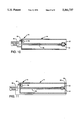
- FIG. 3 is a perspective view of a coaxial cavity resonator of the invention.
- FIG. 4 is a cross-sectional view of the coaxial cavity resonator of FIG. 3 taken through 4--4.
- FIG. 5 is a schematic diagram of a use of the invention with an internal combustion engine.
- FIG. 6 is a cross-sectional view of an alternative embodiment of the coaxial resonator of the invention.
- FIG. 7 is an end view of the alternative embodiment of FIG. 6.
- FIGS. 8-11 are schematic diagrams of alternate modifications of the coaxial resonator of the invention.
- FIG. 1 An apparatus for providing an ignition source for internal combustion engines is shown in FIG. 1.
- the apparatus comprises a radio frequency (RF) oscillator 12, an amplifier 14, and a coaxial cavity resonator 16. While a specific embodiment of the invention employed in an automotive engine is provided herein for illustrative purposes, it should be understood by those skilled in the art that other embodiments and alternatives could be employed in light of the overall teachings of the disclosure.
- RF radio frequency
- the RF oscillator 12 operates from a conventional automobile power supply 18, such as a 12-volt battery, and is operably coupled with an electronic ignition control device 20.
- a conventional automobile ignition system is shown in FIG. 2 and includes a battery 24, electronic ignition 26, and a spark plug 28. Comparing FIG. 1 with FIG. 2, it can be seen that coaxial cavity resonator 16 replaces the spark plug 28 in the conventional ignition system and RF oscillator 12 and amplifier 14 are added to the circuit, in order to provide plasma 30 at the terminal end of the resonator 16.
- the prior art provides elongated spark plug 28 having opposed ends 32,34 wherein end 32 is coupled with electronic ignition 26 and end 34 includes electrodes 36 and 38 defining a gap 40 therebetween. Threads 42 engage a conventional motorblock such that electrodes 36 and 38 are exposed within a combustion chamber of a conventional automobile engine.
- the spark plug 28 is energized and generates a plasma in the gap 40, the plasma or ignition energy is contained only within that gap. That is to say, the ignition energy of the spark plug 28 is localized to the area between the electrodes 36 and 38.
- the ignition energy of spark plug 28 is sufficient to burn air/fuel mixtures of less than 19:1, but mixtures any leaner generally will not be reliably combusted.
- the RF oscillator 12 of FIG. 1, preferably is capable of generating frequencies between about 400 MHz and 4 GHz.
- the advantage of generating frequencies of this magnitude is that it allows the geometry of the coaxial cavity resonator 16 to be small enough to permit adaptation of the resonator to a conventional spark plug receptacle in an existing automobile engine.
- RF oscillator 12 is adaptable to be powered by a conventional automobile power system such as a 12-volt supply.
- the resonant frequency generated by the RF oscillator 12 is then amplified by amplifier 14 to generate a plasma.
- the RF oscillator 12 and amplifier 14 are combined in a single class-C amplifier with resonator 16 acting as a tuning element.
- the RF voltage is amplified between 200 and 30,000 times to create a plasma allowing a plasma to be generated which is significantly larger than the spark generated by conventional spark plug, and in turn this allows a much leaner air/fuel mixture to be burned efficiently.
- a plasma 30 of approximately 0.25 to 10 cm. in length can be generated by the apparatus, which allows a much larger area of a combustion chamber to be energized relative to the ignition energy of a conventional spark plug.
- This larger energization area permits much less uniform combustion chamber air/fuel distribution, i.e., leaner mixtures, to be combusted, as explained hereinbefore.
- a further advantage of this larger energization area is that at stoichiometric ratios fuels are combusted more fully and with fewer pollutants being emitted to the atmosphere than with the ignition energy of a spark plug.
- the resonator 16 as shown in FIGS. 3 and 4, includes a conductive cavity housing 44, a center conductor 46, an RF connector 48 and an electrode 50.
- the cavity housing 44 is preferably hollow and generally cylindrical in shape and has solid annular structure presenting an outer surface 52 and inner surface 54, thereby creating a cavity 47.
- the housing 44 is preferably one-quarter of the electrical wavelength in length. In the preferred operating range of 1.5 GHz to 2.5 GHz, a housing 44 length of 1 to 5.5 cm. is preferred.
- the electrical wavelength is the length of a sinusoidal excitation oscillation signal as it is guided through cavity 47.
- the center conductor 46 is a rod of generally cylindrical shape, preferably between about 0.05 and 2 cm. in diameter, presenting opposed ends wherein said ends generally lie along a single axis which is the central longitudinal axis of housing 44.
- the cavity housing 44 and center conductor 46 are shorted together at one end 51 and open at the other end 53 such that cavity housing 44 generally surrounds and lies along the same axis as center conductor 46, as seen in FIGS. 3 and 4.
- center conductor 46 should be approximately equal to that of the cavity housing 44 and adjusted to maximize the field strength at open end 53 for a given geometry of electrode 50.
- the diameter of center conductor 46 is determined relative to a diameter defined by inner surface 54, preferably between 1.2 and 3 cm. This diameter is determined with respect to the impedance created in resonator 16 and a voltage standing wave ratio of the resonator 16. A trade off must be made between matching the impedance of resonator 16 and producing a maximum standing wave ratio. It is preferred to obtain a ratio between the diameter of center conductor 46 and the diameter of inner surface 54 which produces the most voltage at electrode 50 with minimal power losses due to unmatched impedance between resonator 16 and the RF oscillator 12.
- the RF connector 48 is attached to resonator 16 adjacent shorted end 51 of the cavity housing 44.
- the electrode 50 is formed of a metal or semi-metallic conductor, preferably stainless steel, which can withstand the temperature conditions near the plasma discharge without deformation, oxidation or loss.
- the electrode 50 is attached to the open end of the center conductor 46 and is of a generally teardrop shape with an apex 56 as its endmost point.
- the electrical length of the resonator 16 is preferably one-quarter of the resonant frequency wavelength generated by RF oscillator 12 so that the input voltage may be resonantly amplified to produce a plasma at the open end of the resonator 16.
- the cavity housing 44 and center conductor 46 are preferably composed of material taken from the group of copper, aluminum or other good electrical conductor in order to provide high conductivity and low power absorption in the cavity housing 44.
- low electrical loss and non-porous ceramic dielectric materials such as one selected from the group consisting of aluminum oxide, silicon oxide, magnesium oxide, calcium oxide, barium oxide, magnesium silicate, alumina silicate, and boron nitride may be inserted between the inner surface 54 and center conductor 56 in order to fill the cavity 47 to minimize physical perturbation of an engine combustion chamber and electrical perturbation to the resonator 16.
- RF connector 48 preferably forms a single loop feed 58 at the base. This allows the resonator 16 to operate at a high potential and corresponding E field at the single electrode 50 by virtue of the cavity being electrically one-quarter of resonant frequency wavelength in length.
- the single loop feed 58 may be replaced by a feed element in capacitive relation to center conductor 46 or in direct connection with center conductor 46 at a point displaced from but near shorted end 51, as known to those skilled in the art.
- the plasma generated by the ignition system shown in FIG. 1 is non-propelled which is a significant departure from the prior art.
- plasma ignition systems have required the plasma to be propelled through a combustion chamber of an engine, and hence, large amounts of power were necessary in order to propel this plasma.
- the plasma in non-propelled, thus allowing a much smaller power consumption in the system.
- the apparatus of FIG. 1, preferably, requires less power than the approximately 1000 watts required by the prior art.
- the invention is shown in connection with the operation of a cylinder 60 of an internal combustion engine. It is understood that a separate resonator 16 is required for each cylinder of the engine.
- the apparatus receives a timing signal from a timing wheel 62 through a power switching or frequency control circuit 64 which operates to turn an RF power source 66 on and off at the proper time.
- RF power source 66 may be RF oscillator 12 combined with amplifier 14 (FIG. 1) and powered by a 12-volt battery such as is commonly found in today's automobiles.
- the RF power source 66 When a signal is received from the power switching or frequency control circuit 64, the RF power source 66 is turned on and a distributor 68 sends the amplified RF power to the resonator 16 which is attached to a cylinder head 70 of a combustion chamber 72 and in communication therewith thereby creating a plasma which ignites an air/fuel mixture in the combustion chamber 72.
- the resonator 16 is attached to cylinder head 70 by means of a conventional threaded connection or is integral to cylinder head 70 [not shown].
- the ignition of the air/fuel mixture causes the displacement of a piston 74 which turns the timing wheel 62 to set the next firing sequence. Because the plasma generated reaches well into the combustion chamber as compared to the ignition energy of a conventional spark plug, air/fuel mixtures which are very lean, that is, greater than 19:1, can be burned efficiently thereby increasing fuel economy and decreasing the emission of pollutants into the atmosphere.
- combustion chamber 72 is treated as a perturbing element to the resonator 16, such that the frequency of the combined combustion chamber 72 and resonator 16 will be related to the position of piston 74.
- the resonator is then excited at the resonant frequency of the combined combustion chamber 72 and resonator 16, and when the piston 74 reaches the desired position, the cavity is maximized, as known to those skilled in the art, thus enabling a plasma to be generated at the electrode 50 at the proper time.
- FIG. 6 Another embodiment of the invention is shown in FIG. 6.
- This embodiment includes cavity housing 144, center conductor 146, cavity 147, RF connection 148, and electrode 150.
- the embodiment of FIG. 6 is identical to that explained hereinbefore except that center conductor 146 and electrode 150 have structures defining a fuel line 76 within center conductor 146 and electrode 150.
- fuel is pumped from a fuel tank 78 by a fuel pump 80 through fuel line 76 wherein the fuel is delivered through one or more openings 82 contained within electrode 150.
- openings 82 Two openings are shown in FIG. 7, though other configurations and numbers of openings 82 could be used. In this manner, the fuel is introduced directly at the source of the ignition energy, thereby allowing very efficient combustion to be achieved.
- FIGS. 8-11 illustrate four alternative modifications to the invention disclosed above for altering the size and/or movement of the plasma generated by resonator 44.
- the physical extent of the plasma generated by resonator 44 is governed by the geometry of the electrode 50 and the magnitude of the voltage at the apex 56.
- the purpose of the modifications, as shown in FIGS. 8-11, is to increase the volume of space in the combustion chamger 72 with which the plasma to be generated will interact.
- the plasma created by the electrode 50 is quasi-neutral, i.e., the plasma contains roughly equal numbers of electrons and positive ions.
- the positive ions remain virtually stationary with respect to the highly mobile, energetic electrons. Energetic electrons create positive ions in collision with neutral atoms and molecules, and the chemical combination of specific ions results in combustion.
- RF feed 58 is electrically insulated from housing 44 and housing 44 is insulated from cylinder head 70.
- a DC or quasi-steady AC potential is then applied to housing 44 and center conductor 46 without effecting the resonance of cavity 47. This electrostatic potential influences the plasma, either attracting or repelling electrons.
- the overall potential of cavity 47 can be modulated with respect to combustion chamber 72 in a variety of ways, as depicted in FIGS. 8-11.
- the goal of the modulation is to modify the composite electrostatic field in such a manner as to enlarge the volume of the plasma generated or translate the plasma further into combustion chamber 72 and away from electrode 50. These modulations are achieved through either sinusoidal excitations, sawtooth excitations or ramped excitations of fixed or modulated amplitudes or frequencies.
- the entire cavity resonator 16 is electrically insulated from cylinder head 70 by an insulating material 84 such as dielectric material described above.
- the entire resonator 16 can then be excited by external modulation source 86 thereby causing resonator 16 to act as a lumped conductive circuit element at the modulation frequencies.
- FIG. 9 illustrates center conductor 46 being DC isolated from resonator housing 44 by insulating material 84.
- Resonator housing 44 is then grounded to cylinder head 70 and modulation source 86 is applied to the base of center conductor 46, as shown in FIG. 9.
- Capacitance between the base of center electrode 46 and housing 44 enables the resonator 16 to resonate as if conductor 46 were normally connected thereto.
- electrode 50 is surrounded by conductive layer 90, such as copper, aluminum or other good conductor, which is in capacitive relation to the electrode 50 by means of a high temperature dielectric, such as mica (not shown), placed between electrode 50 and conductive layer 90.
- conductive layer 90 such as copper, aluminum or other good conductor, which is in capacitive relation to the electrode 50 by means of a high temperature dielectric, such as mica (not shown), placed between electrode 50 and conductive layer 90.
- a modulation voltage from modulation source 86 is then applied between conductive layer 90 and housing 44 and grounded to cylinder head 70.
- the potential applied to conductive layer 90 would then influence the motion of the plasma generated, wherein conductive layer 90 is designed not to interfere with the high field region of electrode 50.
- FIG. 11 illustrates a modulation voltage from modulation source 86 being applied between apex 56 of electrode 50 and an annular ring 92 which is insulated from housing 44 by insulating material 84.
- the fields produced between apex 56 and annular ring 92 would then influence the motion of the plasma generated.
Abstract
Description
Claims (35)
Priority Applications (1)
| Application Number | Priority Date | Filing Date | Title |
|---|---|---|---|
| US08/164,660 US5361737A (en) | 1992-09-30 | 1993-12-09 | Radio frequency coaxial cavity resonator as an ignition source and associated method |
Applications Claiming Priority (2)
| Application Number | Priority Date | Filing Date | Title |
|---|---|---|---|
| US95444592A | 1992-09-30 | 1992-09-30 | |
| US08/164,660 US5361737A (en) | 1992-09-30 | 1993-12-09 | Radio frequency coaxial cavity resonator as an ignition source and associated method |
Related Parent Applications (1)
| Application Number | Title | Priority Date | Filing Date |
|---|---|---|---|
| US95444592A Continuation | 1992-09-30 | 1992-09-30 |
Publications (1)
| Publication Number | Publication Date |
|---|---|
| US5361737A true US5361737A (en) | 1994-11-08 |
Family
ID=25495425
Family Applications (1)
| Application Number | Title | Priority Date | Filing Date |
|---|---|---|---|
| US08/164,660 Expired - Lifetime US5361737A (en) | 1992-09-30 | 1993-12-09 | Radio frequency coaxial cavity resonator as an ignition source and associated method |
Country Status (1)
| Country | Link |
|---|---|
| US (1) | US5361737A (en) |
Cited By (61)
| Publication number | Priority date | Publication date | Assignee | Title |
|---|---|---|---|---|
| EP0698953A1 (en) * | 1994-08-25 | 1996-02-28 | Hughes Aircraft Company | Corona source for producing corona discharge and fluid waste treatment with corona discharge |
| US5673554A (en) * | 1995-06-05 | 1997-10-07 | Simmonds Precision Engine Systems, Inc. | Ignition methods and apparatus using microwave energy |
| US5689949A (en) * | 1995-06-05 | 1997-11-25 | Simmonds Precision Engine Systems, Inc. | Ignition methods and apparatus using microwave energy |
| US5734353A (en) * | 1995-08-14 | 1998-03-31 | Vortekx P.C. | Contrawound toroidal helical antenna |
| US5845480A (en) * | 1996-03-13 | 1998-12-08 | Unison Industries Limited Partnership | Ignition methods and apparatus using microwave and laser energy |
| US6188558B1 (en) | 1997-02-05 | 2001-02-13 | Carlos Bettencourt Lacerda | Internal combustion engine with rail spark plugs and rail fuel injectors |
| WO2003046374A1 (en) * | 2001-11-21 | 2003-06-05 | Robert Bosch Gmbh | High-frequency ignition for an internal combustion engine |
| WO2004020820A1 (en) * | 2002-08-28 | 2004-03-11 | Robert Bosch Gmbh | Device for igniting an air-fuel-mixture in an internal combustion engine by means of a high frequency electric energy source |
| US6745744B2 (en) | 2000-06-08 | 2004-06-08 | Szymon Suckewer | Combustion enhancement system and method |
| US20040129241A1 (en) * | 2003-01-06 | 2004-07-08 | Freen Paul Douglas | System and method for generating and sustaining a corona electric discharge for igniting a combustible gaseous mixture |
| US6782875B2 (en) | 2001-08-29 | 2004-08-31 | Hitoshi Yoshimoto | Systems and methods for conditioning or vaporizing fuel in a reciprocating internal combustion engine |
| US6796278B2 (en) | 2001-05-24 | 2004-09-28 | Southwest Research Institute | Methods and apparatuses for laser ignited engines |
| EP1544457A1 (en) * | 2003-12-20 | 2005-06-22 | Robert Bosch Gmbh | Device for igniting an air-fuel mixture in a combustion engine |
| WO2005068829A1 (en) * | 2004-01-15 | 2005-07-28 | Robert Bosch Gmbh | Device and method for igniting an air-fuel mixture by means of a high-frequency resonator |
| US20060260580A1 (en) * | 2005-05-18 | 2006-11-23 | Hitoshi Yoshimoto | Devices and methods for conditioning or vaporizing liquid fuel in an internal combustion engine |
| US20060260581A1 (en) * | 2005-05-18 | 2006-11-23 | Hitoshi Yoshimoto | Devices and methods for conditioning or vaporizing liquid fuel in an intermittent combustion engine |
| US20090107437A1 (en) * | 2007-10-31 | 2009-04-30 | Caterpillar Inc. | RF igniter having integral pre-combustion chamber |
| US20090194051A1 (en) * | 2008-01-31 | 2009-08-06 | Smith James E | Plasma Generating Ignition System and Associated Method |
| WO2008064002A3 (en) * | 2006-11-13 | 2009-09-24 | Kc Energy Llc | Rf systems and methods for processing salt water |
| WO2010015757A1 (en) * | 2008-08-05 | 2010-02-11 | Renault S.A.S. | Monitoring of the excitation frequency of a radiofrequency spark plug |
| US20100116257A1 (en) * | 2007-03-28 | 2010-05-13 | Renault S.A.S | Optimum control of the resonant frequency of a resonator in a radiofrequency ignition system |
| DE102006037039B4 (en) * | 2006-08-08 | 2010-06-24 | Siemens Ag | High-frequency ignition device |
| US20100175655A1 (en) * | 2009-01-12 | 2010-07-15 | Federal-Mogul Ignition Company | Igniter system for igniting fuel |
| US20100282198A1 (en) * | 2009-05-08 | 2010-11-11 | Federal-Mogul Corporation | Corona ignition with self-tuning power amplifier |
| US20110025139A1 (en) * | 2009-08-03 | 2011-02-03 | Schulte David J | Power generator |
| US20110114071A1 (en) * | 2008-07-23 | 2011-05-19 | Borgwarner Inc. | Igniting combustible mixtures |
| US20110127776A1 (en) * | 2009-08-03 | 2011-06-02 | Schulte David J | Power generator |
| US20110175691A1 (en) * | 2008-01-31 | 2011-07-21 | West Virginia University | Compact Electromagnetic Plasma Ignition Device |
| US8065959B1 (en) * | 2009-06-22 | 2011-11-29 | Shulte David J | Explosive device |
| US8104406B1 (en) | 2009-06-22 | 2012-01-31 | Shulte David J | Explosive device |
| US20130119865A1 (en) * | 2010-07-07 | 2013-05-16 | Imagineering, Inc. | Plasma generation device |
| EP1941157A4 (en) * | 2005-09-09 | 2013-09-04 | Btu Int | Microwave combustion system for internal combustion engines |
| US8727242B2 (en) | 2010-02-13 | 2014-05-20 | Mcalister Technologies, Llc | Fuel injector assemblies having acoustical force modifiers and associated methods of use and manufacture |
| US8746197B2 (en) * | 2012-11-02 | 2014-06-10 | Mcalister Technologies, Llc | Fuel injection systems with enhanced corona burst |
| US20140283780A1 (en) * | 2008-01-31 | 2014-09-25 | West Virginia University | Quarter wave coaxial cavity igniter for combustion engines |
| US8919377B2 (en) | 2011-08-12 | 2014-12-30 | Mcalister Technologies, Llc | Acoustically actuated flow valve assembly including a plurality of reed valves |
| US8997725B2 (en) | 2008-01-07 | 2015-04-07 | Mcallister Technologies, Llc | Methods and systems for reducing the formation of oxides of nitrogen during combustion of engines |
| CN104612835A (en) * | 2015-01-07 | 2015-05-13 | 大连理工大学 | Plasma ignition combustion-supporting device with microwave coaxial resonant cavity |
| US9051909B2 (en) | 2008-01-07 | 2015-06-09 | Mcalister Technologies, Llc | Multifuel storage, metering and ignition system |
| US9169814B2 (en) | 2012-11-02 | 2015-10-27 | Mcalister Technologies, Llc | Systems, methods, and devices with enhanced lorentz thrust |
| US9169821B2 (en) | 2012-11-02 | 2015-10-27 | Mcalister Technologies, Llc | Fuel injection systems with enhanced corona burst |
| US20150322913A1 (en) * | 2013-01-22 | 2015-11-12 | Imagineering, Inc. | Plasma generating apparatus and internal combustion engine |
| US9194337B2 (en) | 2013-03-14 | 2015-11-24 | Advanced Green Innovations, LLC | High pressure direct injected gaseous fuel system and retrofit kit incorporating the same |
| US9200561B2 (en) | 2012-11-12 | 2015-12-01 | Mcalister Technologies, Llc | Chemical fuel conditioning and activation |
| US20150349499A1 (en) * | 2014-06-02 | 2015-12-03 | Freescale Semiconductor, Inc. | Device and method for connecting an rf generator to a coaxial conductor |
| DE10150167B4 (en) * | 2001-10-11 | 2016-01-07 | Volkswagen Ag | Internal combustion engine with improved high-frequency ignition |
| US9371787B2 (en) | 2008-01-07 | 2016-06-21 | Mcalister Technologies, Llc | Adaptive control system for fuel injectors and igniters |
| EP3037651A1 (en) * | 2013-08-21 | 2016-06-29 | Imagineering, Inc. | Ignition system for internal combustion engine, and internal combustion engine |
| US9518555B2 (en) | 2014-12-04 | 2016-12-13 | Freescale Semiconductor, Inc. | Radiation devices |
| WO2017013393A1 (en) * | 2015-07-20 | 2017-01-26 | Sunimex Ltd | A control method and device for rf ignition of internal combustion engines |
| US9581116B2 (en) | 2008-01-07 | 2017-02-28 | Mcalister Technologies, Llc | Integrated fuel injectors and igniters and associated methods of use and manufacture |
| JPWO2015182774A1 (en) * | 2014-05-29 | 2017-06-01 | イマジニアリング株式会社 | Injector built-in injector |
| EP3150840A4 (en) * | 2014-05-29 | 2017-06-21 | Imagineering, Inc. | Injector having in-built ignition system |
| US9716371B2 (en) | 2013-12-12 | 2017-07-25 | Federal-Mogul Ignition Company | Non-invasive method for resonant frequency detection in corona ignition systems |
| US9873315B2 (en) | 2014-04-08 | 2018-01-23 | West Virginia University | Dual signal coaxial cavity resonator plasma generation |
| WO2018142036A1 (en) * | 2017-02-06 | 2018-08-09 | Polygon Physics | Plasma source |
| US20190186435A1 (en) * | 2017-12-20 | 2019-06-20 | Plasma Igniter, LLC | Fuel Injection Using a Dielectric of a Resonator |
| US10859358B1 (en) * | 2017-04-04 | 2020-12-08 | The United States Of America As Represented By The Secretary Of The Army | Radio frequency igniter |
| US10989162B2 (en) | 2014-05-16 | 2021-04-27 | West Virginia University | Combustion environment diagnostics |
| US11585312B1 (en) * | 2021-09-13 | 2023-02-21 | Southwest Research Institute | Focused microwave or radio frequency ignition and plasma generation |
| US11725586B2 (en) * | 2017-12-20 | 2023-08-15 | West Virginia University Board of Governors on behalf of West Virginia University | Jet engine with plasma-assisted combustion |
Citations (7)
| Publication number | Priority date | Publication date | Assignee | Title |
|---|---|---|---|---|
| US3473879A (en) * | 1965-09-25 | 1969-10-21 | Siemens Ag | Shock wave burner |
| US4416226A (en) * | 1981-06-02 | 1983-11-22 | Nippon Soken, Inc. | Laser ignition apparatus for an internal combustion engine |
| US4446826A (en) * | 1981-01-07 | 1984-05-08 | Hitachi, Ltd. | Ignition system for internal combustion engine |
| US4523552A (en) * | 1982-04-29 | 1985-06-18 | Nippondenso Co., Ltd. | Ignition system for engine |
| US4561406A (en) * | 1984-05-25 | 1985-12-31 | Combustion Electromagnetics, Inc. | Winged reentrant electromagnetic combustion chamber |
| US4760820A (en) * | 1983-07-20 | 1988-08-02 | Luigi Tozzi | Plasma jet ignition apparatus |
| US4852529A (en) * | 1986-03-07 | 1989-08-01 | Bennett Automotive Technology Pty. Ltd. | Laser energy ignition system |
-
1993
- 1993-12-09 US US08/164,660 patent/US5361737A/en not_active Expired - Lifetime
Patent Citations (7)
| Publication number | Priority date | Publication date | Assignee | Title |
|---|---|---|---|---|
| US3473879A (en) * | 1965-09-25 | 1969-10-21 | Siemens Ag | Shock wave burner |
| US4446826A (en) * | 1981-01-07 | 1984-05-08 | Hitachi, Ltd. | Ignition system for internal combustion engine |
| US4416226A (en) * | 1981-06-02 | 1983-11-22 | Nippon Soken, Inc. | Laser ignition apparatus for an internal combustion engine |
| US4523552A (en) * | 1982-04-29 | 1985-06-18 | Nippondenso Co., Ltd. | Ignition system for engine |
| US4760820A (en) * | 1983-07-20 | 1988-08-02 | Luigi Tozzi | Plasma jet ignition apparatus |
| US4561406A (en) * | 1984-05-25 | 1985-12-31 | Combustion Electromagnetics, Inc. | Winged reentrant electromagnetic combustion chamber |
| US4852529A (en) * | 1986-03-07 | 1989-08-01 | Bennett Automotive Technology Pty. Ltd. | Laser energy ignition system |
Cited By (105)
| Publication number | Priority date | Publication date | Assignee | Title |
|---|---|---|---|---|
| EP0698953A1 (en) * | 1994-08-25 | 1996-02-28 | Hughes Aircraft Company | Corona source for producing corona discharge and fluid waste treatment with corona discharge |
| US5549795A (en) * | 1994-08-25 | 1996-08-27 | Hughes Aircraft Company | Corona source for producing corona discharge and fluid waste treatment with corona discharge |
| US5649507A (en) * | 1994-08-25 | 1997-07-22 | Hughes Aircraft Company | Corona discharge ignition system |
| US5655210A (en) * | 1994-08-25 | 1997-08-05 | Hughes Aircraft Company | Corona source for producing corona discharge and fluid waste treatment with corona discharge |
| US5673554A (en) * | 1995-06-05 | 1997-10-07 | Simmonds Precision Engine Systems, Inc. | Ignition methods and apparatus using microwave energy |
| US5689949A (en) * | 1995-06-05 | 1997-11-25 | Simmonds Precision Engine Systems, Inc. | Ignition methods and apparatus using microwave energy |
| US5734353A (en) * | 1995-08-14 | 1998-03-31 | Vortekx P.C. | Contrawound toroidal helical antenna |
| US5952978A (en) * | 1995-08-14 | 1999-09-14 | Vortekx, Inc. | Contrawound toroidal antenna |
| US5845480A (en) * | 1996-03-13 | 1998-12-08 | Unison Industries Limited Partnership | Ignition methods and apparatus using microwave and laser energy |
| US6188558B1 (en) | 1997-02-05 | 2001-02-13 | Carlos Bettencourt Lacerda | Internal combustion engine with rail spark plugs and rail fuel injectors |
| US6745744B2 (en) | 2000-06-08 | 2004-06-08 | Szymon Suckewer | Combustion enhancement system and method |
| US6796278B2 (en) | 2001-05-24 | 2004-09-28 | Southwest Research Institute | Methods and apparatuses for laser ignited engines |
| US7036492B2 (en) | 2001-08-29 | 2006-05-02 | Hitoshi Yoshimoto | Systems and methods for conditioning or vaporizing liquid fuel in an intermittent combustion engine |
| US6782875B2 (en) | 2001-08-29 | 2004-08-31 | Hitoshi Yoshimoto | Systems and methods for conditioning or vaporizing fuel in a reciprocating internal combustion engine |
| DE10150167B4 (en) * | 2001-10-11 | 2016-01-07 | Volkswagen Ag | Internal combustion engine with improved high-frequency ignition |
| US20040112350A1 (en) * | 2001-11-21 | 2004-06-17 | Richard Schleupen | High-frequency ignition system for an internal combustion engine |
| WO2003046374A1 (en) * | 2001-11-21 | 2003-06-05 | Robert Bosch Gmbh | High-frequency ignition for an internal combustion engine |
| US6913006B2 (en) | 2001-11-21 | 2005-07-05 | Robert Bosch Gmbh | High-frequency ignition system for an internal combustion engine |
| US7204220B2 (en) | 2002-08-28 | 2007-04-17 | Robert Bosch Gmbh | Device for igniting an air-fuel mixture in an internal combustion engine by means of a high frequency electric energy source |
| WO2004020820A1 (en) * | 2002-08-28 | 2004-03-11 | Robert Bosch Gmbh | Device for igniting an air-fuel-mixture in an internal combustion engine by means of a high frequency electric energy source |
| US6883507B2 (en) | 2003-01-06 | 2005-04-26 | Etatech, Inc. | System and method for generating and sustaining a corona electric discharge for igniting a combustible gaseous mixture |
| US20040129241A1 (en) * | 2003-01-06 | 2004-07-08 | Freen Paul Douglas | System and method for generating and sustaining a corona electric discharge for igniting a combustible gaseous mixture |
| EP1544457A1 (en) * | 2003-12-20 | 2005-06-22 | Robert Bosch Gmbh | Device for igniting an air-fuel mixture in a combustion engine |
| WO2005068829A1 (en) * | 2004-01-15 | 2005-07-28 | Robert Bosch Gmbh | Device and method for igniting an air-fuel mixture by means of a high-frequency resonator |
| US20060260581A1 (en) * | 2005-05-18 | 2006-11-23 | Hitoshi Yoshimoto | Devices and methods for conditioning or vaporizing liquid fuel in an intermittent combustion engine |
| US7404395B2 (en) | 2005-05-18 | 2008-07-29 | Hitoshi Yoshimoto | Devices and methods for conditioning or vaporizing liquid fuel in an intermittent combustion engine |
| US7195005B2 (en) | 2005-05-18 | 2007-03-27 | Hitoshi Yoshimoto | Devices and methods for conditioning or vaporizing liquid fuel in an internal combustion engine |
| US20060260580A1 (en) * | 2005-05-18 | 2006-11-23 | Hitoshi Yoshimoto | Devices and methods for conditioning or vaporizing liquid fuel in an internal combustion engine |
| EP1941157A4 (en) * | 2005-09-09 | 2013-09-04 | Btu Int | Microwave combustion system for internal combustion engines |
| DE102006037039B4 (en) * | 2006-08-08 | 2010-06-24 | Siemens Ag | High-frequency ignition device |
| WO2008064002A3 (en) * | 2006-11-13 | 2009-09-24 | Kc Energy Llc | Rf systems and methods for processing salt water |
| US20100116257A1 (en) * | 2007-03-28 | 2010-05-13 | Renault S.A.S | Optimum control of the resonant frequency of a resonator in a radiofrequency ignition system |
| US8528532B2 (en) * | 2007-03-28 | 2013-09-10 | Renault S.A.S. | Optimum control of the resonant frequency of a resonator in a radiofrequency ignition system |
| US20090107437A1 (en) * | 2007-10-31 | 2009-04-30 | Caterpillar Inc. | RF igniter having integral pre-combustion chamber |
| US9051909B2 (en) | 2008-01-07 | 2015-06-09 | Mcalister Technologies, Llc | Multifuel storage, metering and ignition system |
| US9371787B2 (en) | 2008-01-07 | 2016-06-21 | Mcalister Technologies, Llc | Adaptive control system for fuel injectors and igniters |
| US8997725B2 (en) | 2008-01-07 | 2015-04-07 | Mcallister Technologies, Llc | Methods and systems for reducing the formation of oxides of nitrogen during combustion of engines |
| US9581116B2 (en) | 2008-01-07 | 2017-02-28 | Mcalister Technologies, Llc | Integrated fuel injectors and igniters and associated methods of use and manufacture |
| US7721697B2 (en) * | 2008-01-31 | 2010-05-25 | West Virginia University | Plasma generating ignition system and associated method |
| US9551315B2 (en) * | 2008-01-31 | 2017-01-24 | West Virginia University | Quarter wave coaxial cavity igniter for combustion engines |
| US20110175691A1 (en) * | 2008-01-31 | 2011-07-21 | West Virginia University | Compact Electromagnetic Plasma Ignition Device |
| US9638157B2 (en) * | 2008-01-31 | 2017-05-02 | West Virginia University | Compact electromagnetic plasma ignition device |
| US10001105B2 (en) | 2008-01-31 | 2018-06-19 | West Virginia University | Compact electromagnetic plasma ignition device |
| US10865760B2 (en) | 2008-01-31 | 2020-12-15 | West Virginia University | Compact electromagnetic plasma ignition device |
| US9624898B2 (en) * | 2008-01-31 | 2017-04-18 | West Virginia University | Compact electromagnetic plasma ignition device |
| US8887683B2 (en) * | 2008-01-31 | 2014-11-18 | Plasma Igniter LLC | Compact electromagnetic plasma ignition device |
| US20140327357A1 (en) * | 2008-01-31 | 2014-11-06 | West Virginia University | Compact electromagnetic plasma ignition device |
| US20140283780A1 (en) * | 2008-01-31 | 2014-09-25 | West Virginia University | Quarter wave coaxial cavity igniter for combustion engines |
| US20140283781A1 (en) * | 2008-01-31 | 2014-09-25 | West Virginia University | Compact electromagnetic plasma ignition device |
| US20090194051A1 (en) * | 2008-01-31 | 2009-08-06 | Smith James E | Plasma Generating Ignition System and Associated Method |
| US9605646B2 (en) | 2008-07-23 | 2017-03-28 | Borgwarner, Inc. | Igniting combustible mixtures |
| US8746218B2 (en) * | 2008-07-23 | 2014-06-10 | Borgwarner, Inc. | Igniting combustible mixtures |
| US20110114071A1 (en) * | 2008-07-23 | 2011-05-19 | Borgwarner Inc. | Igniting combustible mixtures |
| US20110203543A1 (en) * | 2008-08-05 | 2011-08-25 | Renault S.A.S. | Monitoring of the excitation frequency of a radiofrequency spark plug |
| WO2010015757A1 (en) * | 2008-08-05 | 2010-02-11 | Renault S.A.S. | Monitoring of the excitation frequency of a radiofrequency spark plug |
| FR2934942A1 (en) * | 2008-08-05 | 2010-02-12 | Renault Sas | CONTROL OF THE FREQUENCY OF EXCITATION OF A RADIOFREQUENCY CANDLE. |
| US8434443B2 (en) | 2009-01-12 | 2013-05-07 | Federal-Mogul Ignition Company | Igniter system for igniting fuel |
| US20100175655A1 (en) * | 2009-01-12 | 2010-07-15 | Federal-Mogul Ignition Company | Igniter system for igniting fuel |
| US20100282198A1 (en) * | 2009-05-08 | 2010-11-11 | Federal-Mogul Corporation | Corona ignition with self-tuning power amplifier |
| US8578902B2 (en) * | 2009-05-08 | 2013-11-12 | Federal-Mogul Corporation | Corona ignition with self-tuning power amplifier |
| US8104406B1 (en) | 2009-06-22 | 2012-01-31 | Shulte David J | Explosive device |
| US8065959B1 (en) * | 2009-06-22 | 2011-11-29 | Shulte David J | Explosive device |
| US8508057B2 (en) * | 2009-08-03 | 2013-08-13 | David J. Schulte | Power generator |
| US8203224B2 (en) * | 2009-08-03 | 2012-06-19 | Schulte David J | Power generator |
| US20110025139A1 (en) * | 2009-08-03 | 2011-02-03 | Schulte David J | Power generator |
| US20110127776A1 (en) * | 2009-08-03 | 2011-06-02 | Schulte David J | Power generator |
| US8727242B2 (en) | 2010-02-13 | 2014-05-20 | Mcalister Technologies, Llc | Fuel injector assemblies having acoustical force modifiers and associated methods of use and manufacture |
| WO2011127298A1 (en) * | 2010-04-08 | 2011-10-13 | West Virginia University | Compact electromagnetic plasma ignition device |
| US8873216B2 (en) * | 2010-07-07 | 2014-10-28 | Imagineering, Inc. | Plasma generation device |
| US20130119865A1 (en) * | 2010-07-07 | 2013-05-16 | Imagineering, Inc. | Plasma generation device |
| US8919377B2 (en) | 2011-08-12 | 2014-12-30 | Mcalister Technologies, Llc | Acoustically actuated flow valve assembly including a plurality of reed valves |
| US9169814B2 (en) | 2012-11-02 | 2015-10-27 | Mcalister Technologies, Llc | Systems, methods, and devices with enhanced lorentz thrust |
| US9631592B2 (en) | 2012-11-02 | 2017-04-25 | Mcalister Technologies, Llc | Fuel injection systems with enhanced corona burst |
| US8746197B2 (en) * | 2012-11-02 | 2014-06-10 | Mcalister Technologies, Llc | Fuel injection systems with enhanced corona burst |
| US8752524B2 (en) | 2012-11-02 | 2014-06-17 | Mcalister Technologies, Llc | Fuel injection systems with enhanced thrust |
| US9169821B2 (en) | 2012-11-02 | 2015-10-27 | Mcalister Technologies, Llc | Fuel injection systems with enhanced corona burst |
| US9200561B2 (en) | 2012-11-12 | 2015-12-01 | Mcalister Technologies, Llc | Chemical fuel conditioning and activation |
| US20150322913A1 (en) * | 2013-01-22 | 2015-11-12 | Imagineering, Inc. | Plasma generating apparatus and internal combustion engine |
| US9194337B2 (en) | 2013-03-14 | 2015-11-24 | Advanced Green Innovations, LLC | High pressure direct injected gaseous fuel system and retrofit kit incorporating the same |
| EP3037651A1 (en) * | 2013-08-21 | 2016-06-29 | Imagineering, Inc. | Ignition system for internal combustion engine, and internal combustion engine |
| EP3037651A4 (en) * | 2013-08-21 | 2017-04-26 | Imagineering, Inc. | Ignition system for internal combustion engine, and internal combustion engine |
| US9831639B2 (en) | 2013-12-12 | 2017-11-28 | Federal-Mogul Ignition Company | Concurrent method for resonant frequency detection in corona ignition systems |
| US9716371B2 (en) | 2013-12-12 | 2017-07-25 | Federal-Mogul Ignition Company | Non-invasive method for resonant frequency detection in corona ignition systems |
| US10193313B2 (en) | 2013-12-12 | 2019-01-29 | Federal-Mogul Ignition Llc | Flexible control system for corona ignition power supply |
| US9991681B2 (en) | 2013-12-12 | 2018-06-05 | Federal-Mogul Ignition Company | Relay-mod method to drive corona ignition system |
| US9873315B2 (en) | 2014-04-08 | 2018-01-23 | West Virginia University | Dual signal coaxial cavity resonator plasma generation |
| US11506169B2 (en) * | 2014-05-16 | 2022-11-22 | West Virginia University | Combustion environment diagnostics |
| US10989162B2 (en) | 2014-05-16 | 2021-04-27 | West Virginia University | Combustion environment diagnostics |
| JPWO2015182774A1 (en) * | 2014-05-29 | 2017-06-01 | イマジニアリング株式会社 | Injector built-in injector |
| EP3150841A4 (en) * | 2014-05-29 | 2017-06-21 | Imagineering, Inc. | Injector having in-built ignition system |
| EP3150840A4 (en) * | 2014-05-29 | 2017-06-21 | Imagineering, Inc. | Injector having in-built ignition system |
| US20150349499A1 (en) * | 2014-06-02 | 2015-12-03 | Freescale Semiconductor, Inc. | Device and method for connecting an rf generator to a coaxial conductor |
| US9531167B2 (en) * | 2014-06-02 | 2016-12-27 | Nxp Usa, Inc. | Device and method for connecting an RF generator to a coaxial conductor |
| US9518555B2 (en) | 2014-12-04 | 2016-12-13 | Freescale Semiconductor, Inc. | Radiation devices |
| CN104612835A (en) * | 2015-01-07 | 2015-05-13 | 大连理工大学 | Plasma ignition combustion-supporting device with microwave coaxial resonant cavity |
| WO2017013393A1 (en) * | 2015-07-20 | 2017-01-26 | Sunimex Ltd | A control method and device for rf ignition of internal combustion engines |
| WO2018142036A1 (en) * | 2017-02-06 | 2018-08-09 | Polygon Physics | Plasma source |
| US10798810B2 (en) | 2017-02-06 | 2020-10-06 | Polygon Physics | Plasma source |
| CN110383957A (en) * | 2017-02-06 | 2019-10-25 | 宝利根物理公司 | Plasma source |
| FR3062770A1 (en) * | 2017-02-06 | 2018-08-10 | Polygon Physics | SOURCE OF PLASMA |
| US10859358B1 (en) * | 2017-04-04 | 2020-12-08 | The United States Of America As Represented By The Secretary Of The Army | Radio frequency igniter |
| US20190186435A1 (en) * | 2017-12-20 | 2019-06-20 | Plasma Igniter, LLC | Fuel Injection Using a Dielectric of a Resonator |
| US11725586B2 (en) * | 2017-12-20 | 2023-08-15 | West Virginia University Board of Governors on behalf of West Virginia University | Jet engine with plasma-assisted combustion |
| US11585312B1 (en) * | 2021-09-13 | 2023-02-21 | Southwest Research Institute | Focused microwave or radio frequency ignition and plasma generation |
| US20230083067A1 (en) * | 2021-09-13 | 2023-03-16 | Southwest Research Institute | Focused Microwave or Radio Frequency Ignition and Plasma Generation |
Similar Documents
| Publication | Publication Date | Title |
|---|---|---|
| US5361737A (en) | Radio frequency coaxial cavity resonator as an ignition source and associated method | |
| CA1048594A (en) | Combustion in an internal combustion engine | |
| US4138980A (en) | System for improving combustion in an internal combustion engine | |
| US6782875B2 (en) | Systems and methods for conditioning or vaporizing fuel in a reciprocating internal combustion engine | |
| EP1588048B1 (en) | System and method for generating and sustaining a corona electric discharge for igniting a combustible gaseous mixture | |
| US4774914A (en) | Electromagnetic ignition--an ignition system producing a large size and intense capacitive and inductive spark with an intense electromagnetic field feeding the spark | |
| US5786667A (en) | Electrodeless lamp using separate microwave energy resonance modes for ignition and operation | |
| US4561406A (en) | Winged reentrant electromagnetic combustion chamber | |
| US10132286B2 (en) | Ignition system for internal combustion engine, and internal combustion engine | |
| US9873315B2 (en) | Dual signal coaxial cavity resonator plasma generation | |
| JP2008082286A (en) | Internal combustion engine, and its igniter | |
| EA019899B1 (en) | Plasma plug for an internal combustion engine | |
| JP2747476B2 (en) | Microwave corona discharge ignition system for internal combustion engine | |
| JP6739348B2 (en) | Ignition unit, ignition system, and internal combustion engine | |
| KR101537763B1 (en) | Spark plug and internal-combustion engine | |
| US20190186435A1 (en) | Fuel Injection Using a Dielectric of a Resonator | |
| JP5294960B2 (en) | Spark ignition internal combustion engine | |
| JP2011007158A (en) | Spark ignition type internal combustion engine | |
| CA1077575A (en) | System for improving combustion in an internal combustion engine | |
| JPS5970886A (en) | Firing method of internal-combustion engine | |
| US20180266382A1 (en) | Ignition system and internal combustion engine | |
| JP2010096144A (en) | Spark-ignition internal combustion engine | |
| WO2018056278A1 (en) | Compression auto-ignition engine | |
| JP2014234743A (en) | Ignition device for internal combustion engine | |
| MXPA06006055A (en) | Method for igniting combustion of fuel in a combustion chamber of an engine, associated device and engine |
Legal Events
| Date | Code | Title | Description |
|---|---|---|---|
| AS | Assignment |
Owner name: WEST VIRGINIA UNIVERSITY, WEST VIRGINIA Free format text: ASSIGNMENT OF ASSIGNORS INTEREST;ASSIGNORS:SMITH, JAMES E.;CRAVEN, ROBERT M.;REEL/FRAME:007103/0714 Effective date: 19940718 Owner name: WEST VIRGINIA UNIVERSITY, WEST VIRGINIA Free format text: ASSIGNMENT OF ASSIGNORS INTEREST;ASSIGNOR:VAN VOORHIES, KURT L.;REEL/FRAME:007103/0693 Effective date: 19940728 Owner name: WEST VIRGINIA UNIVERSITY, WEST VIRGINIA Free format text: ASSIGNMENT OF ASSIGNORS INTEREST;ASSIGNOR:BONAZZA, THOMAS J.;REEL/FRAME:007103/0699 Effective date: 19940726 |
|
| STCF | Information on status: patent grant |
Free format text: PATENTED CASE |
|
| FEPP | Fee payment procedure |
Free format text: PAYOR NUMBER ASSIGNED (ORIGINAL EVENT CODE: ASPN); ENTITY STATUS OF PATENT OWNER: SMALL ENTITY |
|
| FPAY | Fee payment |
Year of fee payment: 4 |
|
| FPAY | Fee payment |
Year of fee payment: 8 |
|
| SULP | Surcharge for late payment |
Year of fee payment: 7 |
|
| FPAY | Fee payment |
Year of fee payment: 12 |