US5367128A - Fast-responsive electromagnetic balance-type weighing apparatus - Google Patents
Fast-responsive electromagnetic balance-type weighing apparatus Download PDFInfo
- Publication number
- US5367128A US5367128A US07/678,334 US67833491A US5367128A US 5367128 A US5367128 A US 5367128A US 67833491 A US67833491 A US 67833491A US 5367128 A US5367128 A US 5367128A
- Authority
- US
- United States
- Prior art keywords
- weighing
- resistor
- weight
- output
- input terminal
- Prior art date
- Legal status (The legal status is an assumption and is not a legal conclusion. Google has not performed a legal analysis and makes no representation as to the accuracy of the status listed.)
- Expired - Lifetime
Links
Images


Classifications
-
- G—PHYSICS
- G01—MEASURING; TESTING
- G01G—WEIGHING
- G01G7/00—Weighing apparatus wherein the balancing is effected by magnetic, electromagnetic, or electrostatic action, or by means not provided for in the preceding groups
- G01G7/02—Weighing apparatus wherein the balancing is effected by magnetic, electromagnetic, or electrostatic action, or by means not provided for in the preceding groups by electromagnetic action
- G01G7/04—Weighing apparatus wherein the balancing is effected by magnetic, electromagnetic, or electrostatic action, or by means not provided for in the preceding groups by electromagnetic action with means for regulating the current to solenoids
Definitions
- This invention relates to an electromagnetic balance-type weighing apparatus for measuring the weight of an object of weighing by detecting a signal designed to automatically generate an electromagnetic force by means of an electromagnetic coil to offset the displacement of the weighing pan (or balance beam) of the apparatus caused by the weight of the object of weighing and, more particularly, it relates to an improvement realized on such a weighing apparatus for fast-responsiveness, enhanced accuracy and hence high reliability.
- FIG. 4 of the accompanying drawings The configuration of a known typical electromagnetic balance-type weighing apparatus is shown in FIG. 4 of the accompanying drawings.
- reference numeral 1 generally denotes a weighing pan/balance beam assembly supported at fulcrum S selected to show a given leverage, the weighing pan being positioned at one end portion 1a of the balance beam for determining the weight of object w placed on it
- reference numeral 2 denotes a circular hole provided at a bent-down section of the other end portion 1b of the balance beam of the assembly 1
- reference numeral 3 denotes a light emitter that emits beams of light toward the hole 2
- reference numerals 4 and 5 respectively denote upper and lower light sensors arranged to receive the beams of light passing through the hole 2.
- reference numeral 6 denotes a differential amplifier for detecting the difference between the beams received by the light sensor 4 and those received by the light sensor 5.
- Reference numeral 7 denotes a proportional integral derivative (hereinafter referred to as PID) operation unit for performing the operation of scalar multiplications, integrations and differentiations on the differential signal it receives and sending out a control voltage determined on the basis of the received signal and reference numeral 8 denotes a driving amplifier for generating a driving voltage corresponding to the received control voltage in order to produce a large electric current.
- PID proportional integral derivative
- Reference numeral 9 denotes an electromagnetic (force) coil designed to pull the other end portion 1b of the balance beam opposite to the weighing pan downward by means of the electromagnetic force generated by the electric current running through it in accordance with the driving voltage
- reference numeral 10 denotes a buffer amplifier for transmitting the voltage generated at resistor R by the electric current running through the electromagnetic coil 9
- reference numeral 11 denotes a low-pass filter (hereinafter referred to as LPF) for producing a DC voltage signal corresponding to the weight of the object of weighing obtained by removing those components of the signal transmitted from the buffer amplifier 10 that are responsible for oscillation and noise.
- LPF low-pass filter
- the weight of the object of weighing can be determined by detecting the output signal of the LPF 11, once the voltage output of the opposite end of the resistor is calibrated for the load of the weighing apparatus.
- This phenomenon can give rise to a very serious problem of extremely low weighing speed particularly when the weighing pan is realized in the form of a conveyor belt that moves objects of weighing on it at a given pitch and a given rate up to the weighing spot in an attempt to maximize the rate or efficiency of the weighing operation. While this problem may be dissolved to some extent by increasing the pitch of differentiation in the PID operation unit 7, such a modification made to the operation unit 7 can prohibit optimization of the control capability of the apparatus which is the principal objective of the differentiation and, at the same time, eventually cause the control system of the apparatus to oscillate and consequently deteriorate its operation.
- the apparatus receives a force F1 at an end of the balance beam L applied by the object of weighing W to the point of weighing of the weighing pan C (realized in the form of a weighing conveyor belt for instance) located at that end of the beam L, which is supported at the fulcrum S, and a sucking force F2 of the electromagnetic coil FC at the other end of the beam L in such a way that the beam L is balanced by the two forces so that the weight of the object of weighing W on the weighing pan C can be determined from the electric current supplied to the electromagnetic coil FC to maintain the balanced condition.
- the weighing pan C (realized in the form of a weighing conveyor belt) is cleared of any object of weighing W, certain electric current should be supplied to the electromagnetic coil FC at a given rate to counterbalance the dead weight of the weighing pan C and keep the balance beam L horizontal by pulling the other end A of the balance beam L downward around the fulcrum S, because otherwise the other end A of the balance beam L will be turned upward by the dead weight of the weighing pan C.
- the electric current supplied to the electromagnetic coil FC should be augmented to increase its sucking force F2 in order to offset the upward movement of the other end A of the balance beam L and keep its balanced condition.
- the weight of the object of weighing w is determined from the increase in the rate of electric current supplied to the electromagnetic coil FC.
- a known electromagnetic balance-type weighing apparatus as described above is, however, accompanied by the problems as described below.
- the dead weight to be offset by the sucking force of the electromagnetic coil FC includes the weight of the conveyor belt and that of the electric motor for driving the conveyor belt and therefore the power requirement of such an apparatus can be considerable.
- the balance beam L is highly sensitive to and can resonate with external vibrations (such as the vibration of the floor where the weighing apparatus is installed), that can also adversely affect the accuracy of operation of the apparatus.
- the balance beam L can significantly vibrate when an object of weighing W is placed on or removed from the weighing pan C because of an abrupt weight imbalance there, a phenomenon that also adversely affects the accuracy of the weighing operation of the apparatus.
- FIG. 23 of the accompanying drawings schematically illustrates the configuration of a known water-proof weighing apparatus using a differential transformer.
- a weighing pan C (in the form of a conveyor belt for instance) is arranged external to a housing B of the apparatus main body and at one end portion of the balance beam L which is separated from the fulcrum S by a short distance for receiving an object of weighing on a part of it.
- a spring SP is rigidly fitted to the other end portion of the balance beam L as viewed from the fulcrum S and the balance of the beam L is secured by the resilient deformation of the spring SP.
- the spring SP acts also as a sensor spring that provides (angular) displacement of the balance beam L with a magnitude which is proportional to the weight of the object of weighing W on the weighing pan C.
- the object of weighing W being weighed on a weighing apparatus having a configuration as described above contains liquid in it, some of the liquid content can flow into the main body of the weighing apparatus through the whatever small space between the holes Ba, Ba of the housing B and the respective supports Ca, Ca. A similar problem may arise when the weighing pan C is washed with water.
- a cylindrical protector hood Pa is fitted around each of the supports Ca, Ca and a water-proof cylinder Pb is arranged along the edge of each of the holes Ba, Ba of the housing B, as shown in FIG. 23.
- a drain ridge Pc is also arranged around the outer periphery of the top of each of the water-proof cylinders Pb, Pb whenever necessary.
- any existing electromagnetic balance-type weighing apparatus is devoid of fast-responsiveness and does not meet the requirement of high precision and high reliability.
- Another object of the present invention is to provide an improved electromagnetic balance-type weighing apparatus that meets the requirement of high precision and high reliability.
- an electromagnetic balance-type weighing apparatus comprising:
- weighing pan means for being displaced as a function of the weight of an object of weighing placed thereon;
- electromagnetic coil means for generating an electromagnetic force to counterbalance the displacement of the weighing pan means
- displacement detector means for detecting the displacement of the weighing pan means
- operation means for performing operations to deter mine a control voltage on the basis of a detection signal transmitted from the displacement detector means;
- weight calculator means for calculating the weight of the object of weighing according to the corresponding electric current supplied from the current transducer means.
- an electromagnetic balance-type weighing apparatus of the type similar to the one as described above having a weighing pan arranged at an end of the balance beam pivotally supported by a fulcrum, the weight applied to the weight-sensing spot of the weighing pan by an object of weighing placed on it being counterbalanced by the electromagnetic force generated by an electric current supplied to the electromagnetic coil arranged at the other end of the balance beam, the weight of the object being determined by detecting the rate of the electric current supplied to the electromagnetic coil, wherein a balancing weight is arranged at the end of the balance beam opposite to the weighing pan so that the balance beam is balanced under the condition where the weighing pan is either loaded or unloaded with the object of weighing.
- an electromagnetic balance-type weighing apparatus comprising:
- a main body of the electromagnetic balance-type weighing apparatus for determining the weight of an object of weighing on the basis of the rate of the electric current supplied to an electromagnetic coil when a load applied to the weighing pan by the object of weighing is offset by the electromagnetic force generated by the electromagnetic coil;
- a housing for accommodating the electromagnetic balance-type weighing apparatus provided with a number of holes through which a weight-sensing portion of the weighing pan is projecting upward;
- a clearance between the housing and the weight-sensing portion is airtightly sealed by elastic members and a number of ventilation pores are arranged at locations other than those of the holes for securing air passage to annihilate any difference of air pressure between the outside and the inside of the housing that may be caused by expansion or contraction of the elastic members.
- the electromagnetic coil means since the electromagnetic coil means is driven to operate by the electric current supplied from the current transducer means, the current running through the electromagnetic coil means changes its flow rate quickly responding to the changes in the control voltage so that the displacement of the weighing pan means may be quickly offset by the electromagnetic force applied by the electromagnetic coil means to enhance the fast-responsiveness of the weighing apparatus.
- an electromagnetic balance-type weighing apparatus With an electromagnetic balance-type weighing apparatus according to the second aspect of the invention, since the imbalance of mass between the weighing pan and the opposite end of the balance beam is reduced by an additional weight so that the requirement for electric current through the electromagnetic coil is significantly reduced when the weighing pan is out of load to consequently reduce the amount of heat generated by the coil and the weighing pan becomes by far less sensitive to external vibrations as compared with any known comparable weighing apparatus, the responsiveness of the weighing apparatus to any external object of weighing is remarkably enhanced in terms of the time required for weighing. Therefore, such a weighing apparatus will be characterized as highly accurate and reliable.
- an electromagnetic balance-type weighing apparatus since the clearance between the holes arranged at the top of the housing and the weight-sensing portion of the weighing pan is airtightly sealed by elastic members to protect the apparatus against external liquid and the internal air pressure of the housing does not show any significant changes because of the ventilation pores arranged on the casing even if the volume of the air inside the casing may be increased or reduced depending on the temperature of the air, making the weight-sensing portion of the weighing pan totally unaffected by the elastic members, the main body of the electromagnetic balance-type weighing apparatus can quickly restore its stabilized condition under any circumstances to become ready for weighing.
- the weighing apparatus is highly responsive to the weight of the object of weighing and provides a high accuracy and reliability of weighing.
- FIG. 1 is a schematic diagram showing the configuration of a first embodiment of the electromagnetic balance-type weighing apparatus of the invention
- FIG. 2 is a graphic illustration of waveforms of signals used for the operation of the embodiment of FIG. 1;
- FIG. 3 is a circuit diagram of a modified embodiment obtained from the embodiment of FIG. 1;
- FIG. 4 is a schematic diagram showing the configuration of a known electromagnetic balance-type weighing apparatus
- FIG. 5 is a block diagram of an A/D converter that can be used for .the embodiment of FIG. 1;
- FIG. 6 is a timing chart to illustrate the operation of the A/D converter of FIG. 5;
- FIG. 7 is a block diagram of part of an A/D converter obtained by modifying the one shown in FIG. 5;
- FIG. 8 is a block diagram of another A/D converter that can also be used for the embodiment of FIG. 1;
- FIG. 9 is a block diagram of still another A/D converter that can also be used for the embodiment of FIG. 1;
- FIG. 10 is a timing chart to illustrate the operation of the A/D converter of FIG. 9;
- FIG. 11 is a partial sectional view of a second embodiment of the electromagnetic balance-type weighing apparatus of the invention, showing only its mechanical system;
- FIG. 12 is a sectional view along II--II line of FIG. 11;
- FIG. 13 is a partially cut-out perspective view of the second embodiment, showing only part of the mechanical system as illustrated in FIG. 11;
- FIG. 14 is a partially cut-out perspective view of the second embodiment similar to FIG. 13 but showing different components
- FIG. 15 is an enlarged sectional view of a ventilation pore of the embodiment of FIG. 11;
- FIG. 16 is an enlarged sectional view of a cable port of the embodiment of FIG. 11;
- FIG. 17 is a schematic illustration of the casing of the embodiment of FIG. 11, showing how it is anchored;
- FIG. 18 is an enlarged sectional view of a packing of the embodiment of FIG. 11;
- FIG. 19 is a sectional view of the principal area of the weight-sensing portion of the embodiment of FIG. 11;
- FIGS. 2O and 21 are schematic illustrations showing the airtight structure of a cable port of the embodiment of FIG. 11, through which a support column runs;
- FIG. 22 is a schematic view of a known electromagnetic balance-type weighing apparatus, depicting the underlying theory.
- FIGS. 23 and 24 are two different schematic views similar to FIG. 22 but depicting different underlying theories.
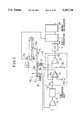
- FIG. 1 shows a schematic diagram of the configuration of a first preferred embodiment of the electromagnetic balance-type weighing apparatus of the invention, where the components which are similar to those of FIG. 4 are indicated by identical reference numerals.
- reference numeral 15 denotes a weighing pan/balance beam assembly, of which the weighing pan is realized in the form of a conveyor belt fitted to one end portion 15a of the balance beam pivotally supported by a fulcrum S at a given point between the opposite ends of the beam and reference numeral 16 denotes a circular hole formed at a bent-down section 15c of the other end portion 15b of the balance beam of the weighing pan/balance beam assembly 15.
- Light sensors 4, 5 receive beams of light coming from a light emitter 3 through the hole 16 and transmit signals corresponding to the beams of light they receive and hence representing the amount of displacement of said balance beam to a differential amplifier 6.
- the output signal from the differential amplifier is transmitted to a PID operation unit 7, which by turn brings forth a control voltage that corresponds to the load applied to the weighing pan 15.
- the PID operation unit 7 may be replaced by a control unit based on the most advanced theories for system control such as a fuzzy control unit involving a membership function. What is important here is that a control unit put to use should be capable of performing mathematic operations on various control parameters in such a manner that said displacement signal may approach zero as close as possible.
- reference numeral 20 denotes a current transducer circuit that supplies an electric current to an electromagnetic coil 9 at a rate corresponding to the control voltage produced by the PID operation unit 7.
- the non-inverted input terminal of the driving amplifier 21 is grounded by way a resistor R0, while the inverted input terminal of the buffer amplifier 22 is connected to its output terminal.
- Reference numeral 23 denotes an A/D converter to be used for converting gross weight signals transmitted from the buffer amplifier 22 by way of a LPF 11 into digital signals and reference numeral 24 denotes a weight calculator for determining the weight of the object of weighing by subtracting the weight of the weighing pan 15 from the total load of the weighing pan represented by the gross weight signal.
- Reference numeral 25 denotes a sensor for determining the timing of bringing an object of weighing onto the weighing pan 15.
- the A/D converter 23 proceeds to an operation of converting a gross weight signal into a corresponding digital signal only when time T has elapsed after receiving a timing signal.
- the load of the weighing pan will show a change as expressed by the trapezoidal line of chart A.
- the PID operation unit 7 adds the derivative (chart B) to the integral and proportional component (chart C) and transmits a signal representing the resultant waveform (chart D) which is generally found between -V1 and -V2.
- the driving amplifier 21 quickly responds to the control voltage Vc as it is fed back from the buffer amplifier 22 so that the output current Ia of the driving amplifier 21 is converged to a value determined by V2/R2 as shown by chart E in FIG. 2.
- the voltage applied to a terminal of the resistor R2, or the power voltage Vb of the buffer amplifier 22 will be -V2 volts as shown by chart F in FIG. 2.
- the weighing pan/balance beam assembly 15 quickly regains its balanced condition if it is temporarily displaced by the load applied to it by the object of weighting placed on the weighing pan.
- the gross weight signal obtained at time T after an object of weighing is put on the weighing pan is converted into a digital signal and sent to the weight calculator 24, which determines the weight of the object of weighing.
- the time T can be made very short and the efficiency of operation of the weighing apparatus will be maximized by so selecting the rate of moving objects of weighing that the time required for each object of weighing to stay on the weighing pan is very close to T.
- the current transducer circuit 20 of the above embodiment is constituted by a driving amplifier 21 and a buffer amplifier 22, it may be alternatively realized in the form of a current transducer circuit 30 having a configuration as shown in FIG. 3.
- the current transducer circuit 30 illustrated in FIG. 3 comprises a driving amplifier 31 for receiving a control voltage from the PID operation unit 7 and providing a transducer voltage gain "1" to produce a large electric current and an inversion type driving amplifier 32 connected with a resistor R2 for detecting electric current and the electromagnetic coil 9 to set up a negative feedback loop and a resistor R4 through which it receives the output signal of the driving amplifier 31.
- Reference numeral 33 denotes a differential amplifier for converting the terminal voltage of the resistor R2 into a weight signal.
- the two light sensors 4, 5 of the above embodiment for detecting the displacement of the weighing pan may be replaced by non optical means such as a differential transformer.
- the first embodiment of the electromagnetic balance-type weighing apparatus of the invention is so designed as to use its electromagnetic coil to set up a negative feedback loop and drive it to operate by means of the electric current running therethrough, the current quickly responds to changes in load applied to the weighing pan and consequently the time required for the apparatus from the detection of a change in the load caused by an object of weighing to the determination of the weight of the object is significantly reduced to improve the efficiency of weighing operation.
- the A/D converter contributes to the improvement of the reliability of the electromagnetic balance-type weighing apparatus as it converts the analog weight signal obtained from the LPF 11 into a corresponding digital value, which is then supplied to the weight calculator 24 so that the latter can perform arithmetic operations quickly and accurately.
- V/F converter A voltage/frequency converter (hereinafter referred to as V/F converter) may be suitably used for the A/D converter because it can simplify the overall configuration and reduce the cost of the A/D conversion circuit.
- FIG. 8 shows a typical configuration of an A/D conversion circuit using a V/F converter.
- reference numeral 31 denotes a V/F converter that, upon receiving an analog signal in the of voltage, generates a pulse signal with a frequency F that corresponds to the voltage v.
- F a frequency that corresponds to the voltage v.
- the frequency of the output signal may vary from zero to 2 MHz as a linear function of the voltage.
- 32 denotes a counter circuit for counting the frequency of the pulse signal coming from the V/F converter. More specifically, it lets the pulse signal pass through an AND circuit 34 and then to a N-bit counter 35 for a given period of time by using a gating signal transmitted from a gating signal generating circuit 33 and causes a latch circuit 36 to latch the result of the counting and generate an output signal representing the digital value of the count.
- Reference numeral 37 denotes a latching pulse generating circuit that generates a latching pulse for each gating pulse which is slightly delayed relative to the rising edge of the gating pulse and reference numeral 38 denotes a resetting pulse generating circuit that generates a resetting pulse to reset the counter 35 for each latching pulse which is slightly delayed relative to the latching pulse but slightly precedes the rising edge of the next gating pulse.
- An A/D conversion circuit having a configuration as described above may be unable to respond to changes in analog signals quickly and accurately that contain high frequency components if the weight signal (analog signal) of the electromagnetic balance-type weighing apparatus needs highly accurate measurement and analysis for its waveform because a relatively long gating time of 32 milliseconds (64K/2 MHz) may be required if a resolution of 16 bits should be achieved.
- This problem may be resolved by reducing the gating time to, for instance, one-eighth of 32 milliseconds, or 4 milliseconds, to increase the rate of sampling and adding eight consecutive counts to realize a resolution of 16 bits.
- the time required to reset the counter 35 should be made negligibly short relative to the period of a pulse signal with the highest possible frequency generated by the V/F converter 31 if such an arrangement should prove practically feasible.
- a conceivable solution to this problem may be the use of a high speed device such as an emitter-coupled logic (hereinafter referred to as ECL), a logic gate that operates at very high speed.
- ECL emitter-coupled logic
- a high speed device is very costly and emits heat at a high rate, giving rise to additional problems including the drift phenomenon that should be newly addressed. Therefore, the use of such a device does not constitute a recommendable solution to the problem.
- FIG. 5 shows a block diagram of an A/D converter proposed as a possible solution to overcome the above problem.
- reference numeral 40 denotes a V/F converter that generates a pulse signal having a frequency that varies as a linear function of the analog voltage applied to it. It may be typically a synchronous V/F converter that generates an output pulse signal in synchronism with the clock signal transmitted from a crystal oscillator 41, the frequency of said output pulse signal varying between zero to 2 MHz in response to the variance in the analog voltage between zero and 10 volt as in the case of the V/F converter 31 described earlier.
- reference numeral 42 denotes a counter, e.g., 16-bit endless counter, for continuously counting the pulse signals transmitted from the V/F converter 40.
- Reference numeral 43 denotes a first latch circuit for latching the count output from the endless counter 42 each time it receives a first latching pulse
- reference numeral 44 denotes a second latch circuit for latching the output of the first latch circuit 43 each time it receives a second latching pulse.
- Reference numeral 45 denotes a latching pulse generating circuit for dividing the frequency of a clock signal coming from the crystal oscillator 41 and generating a first latching signal for every 1 millisecond and reference numeral 46 denotes a first delay circuit for generating a write pulse with a short delay of time d1 relative to the first latching pulse, while reference numeral 47 denotes a second delay circuit for generating a second latching pulse with a slight delay of time d2 relative to the write pulse.
- Reference numeral 48 denotes a subtracter for subtracting the output of the second latch circuit 44 from the output of the first latch circuit 43.
- the result of the subtraction is equal to the value Cn obtained by subtracting the reading An-1 of the endless counter 42 at time Tn-1 when a first latching pulse is generated from the reading An of the counter at time Tn for generation of the next latching pulse and represents a digital value that corresponds to the level of voltage from Tn-1 to Tn expressed in analog form.
- the digital value is equal to the difference between two pulse signals latched with an interval of 1 millisecond that can vary between zero and 2 MHz, it shows a resolution of "2,000" or 11 bits at maximum.
- Reference numeral 49 denotes an integral circuit that generates an output representing the accumulated sum of the results of a given number of times (32) of subtractions made to consecutive inputs and comprises a shift register 491 for sequentially storing the results of subtraction and an adder 492 for adding the data stored in the shift register 491.
- a corresponding latching pulse is generated at time T1 for the pulse signal as illustrated in chart B of FIG. 6 to latch count value A1 to the first latch circuit 43 as shown in chart C of FIG. 6 and a write pulse (chart D in FIG. 6) which is generated with a slight delay relative to the latching pulse triggers an operation of subtracting the immediately preceding count value (A0) stored in the second latch circuit 44 from the count value Al to give out the difference C1, which is then stored in the shift register 491 (chart E of FIG. 6).
- the output of the adder 492 when the results of 32 subtractions C2 through C33 are stored in the shift register 491 is a digital value that corresponds to the level of the voltage expressed in analog form for a period of 32 milliseconds from T1 to T33 and, since the endless counter 42 continuously keeps on counting, no errors are accumulated during the period, making the output of the adder to show a resolution, or an accuracy, of 16 bits.
- the output of the adder 492 will be a digital value that corresponds to the level of the voltage in analog form between T2 and T34. In the same way, a digital value with an accuracy of 16 bits will be obtained for the corresponding analog voltage for every 1 millisecond.
- the A/D converter in FIG. 5 adds the results of subtractions with a level of resolution of 11 bits without further processing them, it may be so configured as to obtain a resolution of 16 bits as illustrated in FIG. 7, where each result of subtraction is multiplied by 2 5 (or five "0"s are added to the end of the result as lower five digits) in shift register 491a and M (an arbitrary number) consecutive results of subtractions expressed by using 16 bits are added in adder 492a, the sum being averaged by a 1/M divider 493.
- the A/D converter in FIG. 5 comprises a 16-bit endless counter 42
- the counter may be replaced by any counter that can count numbers within a limit defined by the number obtained by dividing the output frequency corresponding to the upper end of the scale of the V/F converter by the latching frequency.
- the A/D converter in FIG. 5 may be replaced with a comparable 12-bit or higher-bit counter.
- the digitization may be performed to obtain a desired level of accuracy with a relatively narrow pitch of sampling of incoming analog signals and therefore without requiring a high speed counter to afford a high accuracy of measurement and a high speed waveform analysis.
- FIG. 9 shows a block diagram of an alternative A/D converter proposed to eliminate the problem of the A/D converter of FIG. 8.
- reference numeral 50 denotes a V/F converter for producing a pulse signal with a frequency corresponding to the analog voltage applied thereto. It may typically be a synchronous V/F converter that produces an output pulse signal in synchronism with the clock signal transmitted from a crystal oscillator 51.
- the frequency of the pulse signal transmitted from the V/F converter may vary between zero and 2 MHz in response to the analog voltage applied thereto that can vary zero to 10 volt as in the case of the V/F converter of FIG. 8.
- reference numeral 52 denotes an input changeover switch that forwards the pulse signal from the V/F converter 50 either to a first counter 53 or to a second counter 54 depending on the level of the changeover signal it receives.
- the first and second counters 53, 54 are 12-bit binary counters.
- Reference numeral 55 denotes a changeover signal generating circuit for generating input changeover signals having a level reversed at a frequency, e.g., once for every millisecond, obtained by dividing the frequency of the clock signal from the crystal oscillator 51 and reference numeral 57 denotes a write pulse generating circuit for generating a write pulse each time it receives an output changeover signal with a slight delay of time d1 relative to the rising or falling edge of the output changeover signal which its obtained by reversing the corresponding input changeover signal by means of an inverter 56.
- Reference numeral 58 denotes an output changeover switch for selectively transmitting the output of either the first counter 54 or the second counter 53 depending on the level of the output changeover signal.
- the cut put changeover switch 58 operates reversely relative the input changeover switch 52 and, therefore, selects the output of the second counter 54 when the first counter 53 is operating and that of the first counter 53 when the second counter 54 is operating.
- Reference numeral 59 denotes a resetting circuit for slightly delaying write pulses by time d2 and resetting whichever counter that has completed its operation.
- Reference numeral 60 is an accumulator circuit for producing the total of given number of (32) consecutive inputs, said accumulator circuit comprising a shift register 61 for sequentially storing the counts transmitted from the output change-over switch 58 in synchronism with the corresponding write pulses and an adder 62 for adding the data stored in the shift register.
- the maximum digital value that can be stored in the shift register 61 is "2,000" which is obtained by counting the number of pulses for 1 millisecond of a 2 MHz pulse signal that represents the maximum frequency for the apparatus.
- the apparatus has a resolution of 11 bits.
- the level of the input changeover signal rises to level "H" at time T1 as indicated in chart A of FIG. 10 and, after the input changeover switch 52 is turned to the side of the first counter 53, the number it counts is incremented from zero as indicated by chart B in FIG. 10.
- the input changeover switch 52 When the level of the input changeover signal falls to level "L", the input changeover switch 52 is turned to the side of the second counter 54 so that it starts counting from zero as illustrated in chart C of Fig. At this stage, the count C1 of the first counter 53 for the period of time from T1 to T2 is retained at the output of the counter.
- the output changeover signal goes to level "H" while the second counter 54 is operating as shown in chart D of FIG. 10, and, as the count C1 of the first counter 53 has already been sent to the shift register 61, the count C1 is now stored in the shift register 61 by a write pulse which is delayed by d1 relative to T2 as illustrated in chart E of FIG. 10.
- a reset pulse is sent to the first counter 53 as illustrated in chart F of FIG. 10 to reset the first counter to zero as shown in chart C of FIG. 10.
- the input changeover signal falls again to level "L" at time T3 that comes 1 millisecond later than time T2 to activate the first counter 53 for counting and, when d1 has elapsed since T3, the count C2 of the second counter 54 is stored in the shift register 61 and then the second counter 54 is reset to zero with a further delay of d2 and become ready for the next counting operation.
- next counted value is stored in the shift register 61 when 1 millisecond has elapsed since the previous count.
- the output of the adder 62 will be a digital value corresponding to the level the voltage of the analog signal for the 32 milliseconds from T1 to T33. It should be noted that since the output of the V/F converter 50 and the input changeover signal are synchronized and therefore the time required for switching operation is minimal, the counting operations for the period is conducted continuously and no count will be missed during that period. Consequently, the sum of addition of the counts shows a resolution of 16 bits.
- the output of the adder 62 shows a digital value that corresponds to the level of the analog voltage for the 32 milliseconds from T2 T3.
- the resolution may be so modified as to meet a required level by storing all the counts for a given period of time an operation such as waveform analysis is involved.
- each of the counts may be alternatively multiplied by 2 5 in the shift register 61a of FIG. 7 (or five "0" may be added to the count as lower five digits) and M (an arbitrary number) consecutive counts in 16-bit numbers may be added in the adder 62a as a result of counting to obtain the same digital value with a resolution of 16 bits by dividing the sum of the addition by M in the divider 63.
- an A/D converter having a configuration as described above uses a plurality of counters which are sequentially operated for a given period of time for counting the outputs of the corresponding V/F converter so that the result of a counting operation can be produced as a digital value while one of the remaining counters is operating, the operation of A/D conversion can be carried out with a desired level of resolution and a short period of sampling without requiring high speed counters.
- This feature provides an electromagnetic balance-type weighing apparatus with the advantage of high accuracy measurement and high speed waveform analysis as described earlier.
- FIGS. 11 through 21 show the mechanical system of a second preferred embodiment of the invention as well as the anti-vibration and water-proof contrivances designed to enhance the accuracy of measurement of the apparatus.
- reference numeral 110 denotes a bottom plate removably combined with a cover 170 to form a housing of the apparatus and provided with three legs 111 projecting downward from the front and the rear corners and the middle point of the right edge of the lower surface of the bottom plate (as viewed from the front in FIG. 11) to securely and stably support the apparatus when placed on a flat floor.
- the bottom plate 110 has a cavity 112 on its upper surface surrounded by a rim 110a.
- the bottom plate 110 is provided with a pair of ventilation pores 113 arranged at the middle along its left and right edges (as viewed from the front in FIG. 11) so that the atmosphere and the cavity 112 may communicate with each other.
- each ventilation pore 113 is bored through the center of each pair of the countersinks 113b as illustrated in full detail in FIG. 15.
- a cylindrical hood 113c is arranged coaxially with each of the ventilation pores 113 and projecting downward from the corresponding lower countersink 113b.
- the hoods 113a are so designed as to guard the ventilation pores 113 against any liquid that may be bounced to splash the pores from the floor under the apparatus.
- a piece of water repellent film 113d that passes air but does not pass liquid is bonded to each of the annular steps 113a of the upper countersinks 113b along its periphery in order to prevent any liquid from entering the inside of the casing but secure ventilation for the inside of the apparatus.
- the cavity 112 is also provided with a pair of power cable holes 114 arranged at the middle along the two lateral edges (FIG. 14) and a telecommunication cable hole (not shown).
- each of the cable holes 114 is provided with an annular projection 114a along its side wall, to which an elastic member 114b made of a material such as rubber is engagedly fitted.
- Each of the elastic members 114b has an axial through bore 114b', through which a corresponding cable is arranged, any liquid external to the apparatus being prevented from entering it through the cable holes because of an elastic cylinder 114b" of each of the elastic members 114b firmly pressing the cable running therethrough and airtightly sealing the corresponding cable hole.
- the bottom plate 110 is also provided with left and right rectangular support blocks 116, 117 (as viewed from the front in FIG. 11) arranged in parallel and standing upward from the cavity 112 for supporting a permanent magnet 122, which will be described later (FIG. 14).
- a pair of support pillars 118, 119 are projecting upward from the front and rear left corners of the bottom plate 110.
- a yoke 120 is placed on the upper surfaces of the support blocks 116,117 and rigidly fitted thereto means of screws 121 arranged at its four corners as illustrated in FIG. 13.
- the permanent magnet 122 having a cylindrical shape is rigidly fitted onto the center of the yoke 120 and another yoke 123 is rigidly fitted to the upper surface of the permanent magnet 122 as shown in FIG. 11.
- the yoke 123 has a circular slit 124 arranged therein.
- a horizontal plate 130 is fitted to the rim 110a of the bottom plate 110 at its left corners (as viewed from the front in FIG. 11) by way of rocking plates 132, 133 which are found between the support pillars 118,119. As shown in FIGS. 11, 13 and 14, the horizontal plate 130 is located between the support blocks 116, 117 and below the yoke 120.
- a second horizontal plate 131 is fitted to the tops of the support pillars 118, 119 at its left corners by way of rocking plates 134, 135.
- the horizontal plates 130 and 131 have the same width.
- the load carrying section 140 of the weighing apparatus comprises a horizontal member 141 having a center opening 141a, a vertical member 142 also having a center opening 142a' (FIG. 12) and triangular lateral members 143, 144 connecting the horizontal and vertical members 141 and 142.
- the horizontal plates 130 and 131 are respectively fitted to the bottom and top surfaces 142a and 142b of the vertical member 142 of the load bearing section 140 at their right corners by way of respective rocking plates 136, 137 and 138, 139 (FIGS. 12 and 14).
- the rocking plates 132 through 139 are uniformly shaped, each being flexible at a thin middle area.
- Four of the rocking plates 132 through 139 constitute a front group, while the remaining four constitute a rear group.
- Each of the front and rear groups are so arranged that, when viewed from the front (FIG. 11), they form a rectangle, which is deformed to become a non rectangular parallelogram whenever a load is applied to the load carrying section 140 so that the upper surface of the load carrying section 140 is lowered.
- Balance beam 150 is pivotally fitted to a right top corner of the yoke 123 (as viewed from the front in FIG. 11).
- the balance beam 150 is realized substantially in the form of a flat plate provided with a pair of flanges 151,152 arranged at the right side corners and projecting outward and downward.
- the flanges 151,152 are connected at their respective left lateral sides 151a, 152a to the right lateral side 123a (as viewed from the front in FIG. 11) of said yoke 123 by way of a pair of rocking plates 153, 154 and at their respective bottoms 151b, 152b to the top 123b of the yoke 123 along its right edge by way of another pair of rocking plates 155, 156 (FIG. 12).
- the rocking plates 153 through 156 are uniformly shaped, each being flexible at a thin middle area.
- the vertically arranged rocking plates 153, 154 are intersected at a single and identical point in the thin middle areas by the horizontal rocking plates 155, 156 so that the balance beam may rotatably sup-ported relative to the yoke 123 at a fulcrum which is the point of intersection O of the vertical rocking plates 153, 154 and the horizontal rocking plates 155, 156 (FIG. 11).
- the lateral side of the notch 157 arranged at the right edge of the balance beam 150 (FIG. 13) and the front lateral side of projection 145 projecting leftward from the center of the bottom of the vertical member 142 of the load carrying section 140 (FIG. 14) are connected by a connector plate 158.
- the connector plate 158 is realized in a form having upper and lower flexible narrow and thin areas as illustrated in FIGS. 11 and 12.
- a bobbin 161 having an open bottom is provided under the balance beam 150 to the left of said fulcrum 0 with a flat balancing weight 160 arranged therebetween.
- the fitting axle 161a of the bobbin 161 standing upright from the center of the bobbin main body runs through the through bore 160a of the weight 160 as well as the through bore 150a of the balance beam 150 and is rigidly fitted to the balance beam 150 by means of a nut 162 arranged in the recess 150b of the balance beam 150 so that bobbin 161 and the weight 160 are securely connected to the bottom of the balance beam 150.
- the cylindrical portion, or peripheral wall, 161b of the bobbin 161 is located in the annular slit 124 of the yoke 123.
- a wire is wound around the outer periphery of the cylindrical portion 161b to form a coil 163 that constitutes a magnetic circuit crossing the permanent magnet 122 and the slit 124 of the yoke 123 so that, when it is energized by electricity, it tends to rotate the balance beam 150 counterclockwise around the fulcrum 0 with its electromagnetic force.
- the balance beam 150 is provided with a threaded bore 150c at its left end so that a weight 164 for finely controlling the balance of the beam (as shown by a broken line in FIGS. 11 and 13) may be fitted there by means of a screw if necessary.
- the weight 164 is replaceable for fine control or, alternatively, the apparatus may be so arranged that the balance beam is finely controlled by adjusting the position of the weight 164 by means of a screw.
- a L-shaped plate 165 is fitted to the left edge of the balance beam 150.
- the lower end 165a of the L-shaped beam 165 is detected for its position by a position detector 166 comprising light emitter and light sensors and rigidly fitted to the left edge of the yoke 123.
- the balance beam 150 is provided at its left edge with a fin 167 horizontally projecting from the edge.
- a stopper 168 is rigidly fitted to the upper surface of the yoke 123 to define the upper and lower limits of vertical movement of the fin 167.
- a cover 170 is placed on the top of the rim 110a of the bottom plate 110, the casing of the weighing apparatus being constituted by the bottom plate 110 and the cover 170.
- the cover 170 and the bottom plate 110 are securely connected with each other by means of screws 171 arranged at the flat sections of the four corners of the cover 170 which are located on the respective four corners of the rim 110a of the bottom plate 110 as illustrated in FIG. 17.
- reference numeral 172 denotes a ring-shaped packing and 170b denotes a closed groove arranged along the bottom of the cover 172, into which the ring-shaped packing 173 is press fit.
- the ring-shaped packing 173 has a substantially rectangular cross section having upper and lower projections as illustrated in FIG. 18 which are forced to become flat when the ring-shaped packing 173 is press fit into the groove so that it can effectively prevent liquid from entering the inside of the apparatus.
- a window 174 is provided at the left side wall (as viewed from the front in FIG. 11) to allow access to the fine control weight 164 for adjustment and/or replacement.
- a shutter 175 for the window is removably fitted to the side wall by means of screws 176 with a packing (not shown) arranged between the shutter 175 and the side wall for protection against water.
- another window 177 is provided at the right side wall (as viewed from the front in FIG. 11) to allow access to the electronic circuit (not shown) arranged in the inside of the apparatus.
- a shutter 178 for the window 177 is removably fitted to the side wall by means of screws 179 with a packing (not shown) arranged between the shutter 178 and the side wall for protection against water.
- FIG. 19 It is seen in FIG. 19 that the support pillars 180 through 183 are standing upright through holes 170c of the top wall of the cover 170.
- a vertically extendible bellows 184 is arranged between the peripheral edge of each of the holes 170c and the corresponding one of the support pillars 180 through 183 so that the support pillars 180 through 183 are vertically slidable without hindrance but the watertight condition of the casing is preserved.
- each of the holes 170c of the cover 170 has a flange 170d standing upward, to whose outer upper periphery an 0-ring is engagedly fitted, and the lower end 184a of the corresponding bellows 184 adheres to the flange 170d of the cover 170 due to its centripetal resilient force, while the upper end 184b of the bellows 184 is pressed downward by a washer 189, which will be described later, so that the watertight condition of the casing is perfectly secured.
- the two paired support pillars 180, 181 and 182, 183 are provided with respective common beams 185 and 186, which are longitudinally arranged and securely held to the respective proper positions by means of anchor bolts 187 and washers 189, the latter being arranged between the respective bolts 187 and the beams 185, 186 (FIGS. 11, 12 and 16).
- a conveyor assembly 190 that operates as a weighing pan is securely held by the opposite ends of the beams 185, 186, as the front and rear panels 191a of the frame 191 of the conveyor assembly 190 are rigidly fitted to the beams 185, 186 by means of screws 192.
- Rollers 193 and 194 are rotatably supported by the front and rear panels 191a and a conveyor belt 195 is arranged between the rollers 193 and 194.
- the conveyor belt 195 is so arranged that it is kept in contact with the top panel 191b of the frame 191 at the upper end of it so that the conveyor belt 195 may not sink under the load of the object of weighing W applied to it (FIGS. 11 and 12).
- the roller 193 is driven to rotate by a motor 196 securely fitted to the frame 191.
- 193a denotes a pulley securely fitted to the roller 193
- 197 denotes a belt connecting the pulley 193a and a pulley (not shown) arranged on the motor 196.
- the support pillar 180 is realized as a hollow pipe, through which a power cable 200 (FIG. 11) runs to be led outside by way of a through bore 180a of the top to reach the motor 196.
- the watertight condition of the casing is secured and any possibility of liquid entering there by way of the through bore 180a for the support pillar 180 can be eliminated by arranging either an elastic tube around the cable 200 and the support pillar 180 as illustrated in FIG. 20 or an 0-ring 202 press fit into the space between the cable 200 and the anchor bolt 187.
- the balance beam 150 is subjected to a rotary force trying to drive it clockwise by the load applied to the connector plate 158 by the entire conveyor assembly 190, the motor 196 and the load carrying section 140, whereas, at the left of the fulcrum O, it is subjected to another rotary force trying to drive it counterclockwise by the load applied by the balancing weight 160 and the weight for fine control 164 and the sucking force of the energized coil 163.
- the vertical position of the lower end 165a of the L-shaped plate 165 rigidly fitted to the left edge of the balance beam 150 is detected by the position detector 166 and utilized to regulate the sucking force of the coil 163 by adjusting the rate of the electric current supplied to the coil so that consequently the lower end 165a of the L-shaped is returned to its normal position.
- the rate of the electric current supplied to the coil 163 should be so adjusted that the lower end 165a of the L-shaped plate 165 is found exactly at its normal position when the conveyor belt 195 does not carry any objects of weighing.
- the balance beam 150 tends receive a clockwise rotary force by the weight of the object of weighing and the L-shaped plate 165 at the left edge of the balance beam 150 shows an upward movement deviating itself from the normal position, a movement which is suppressed by the increased sucking force of the coil 163 generated by a corresponding increase in the rate of the electric current supplied to the coil 163.
- the weight of the object of weighing is then determined by the rate or the increase in the rate of electric current.
- the space between the pillars 180 through 183 supporting the weighing pan and the cover 170 is sealed by the bellows 184 and the space surrounding the cable 200 in the through bore 180a of the pillar 180 is also sealed by an appropriate measure as illustrated in FIG. 20 or FIG. 21.
- the cable hole 114 of the bottom plate 110 is protected against liquid. Therefore, the weighing apparatus within the casing is completely free from the risk of being wet if the conveyor belt 190 is washed with water for cleaning.
- the mechanical system of the second embodiment as described above comprises a balancing weight 160 arranged between the balance beam 150 and the bobbin 161 of the electromagnetic coil, the apparatus is free from any significant imbalance that may be caused within the weighing apparatus by the dead weight of the weighing pan so that the rate of the electric current supplied to the electromagnetic coil and hence the heat to be inevitably generated by the electric current can be minimized.
- Non-existence of significant imbalance within the weighing apparatus means that the balance beam 150 is scarcely affected by external vibrations such as those of the floor supporting the apparatus and therefore fast and accurate weighing operations are guaranteed.
- the mechanical system of the second embodiment is completely protected against any intrusion of liquid because all the space between the casing and the support pillars projecting outward through the holes is completely sealed by means of elastic members. Besides, since the inside and the outside of the casing are in communication with each other by way of ventilation pores and therefore the elastic members are not undesirably expanded nor contracted by temperature changes within the casing, readings of the weighing apparatus are not affected by temperature changes.
- the balance beam 150 may be so adjusted that it is balanced under either loaded or unloaded conditions either by altering the shape, weight or fitting position of either the balancing weight 160 or the weight for fine control 164 or, alternatively, by means of the balance beam 150 itself or an accessory.
- the present invention provides a fast-responsive, highly accurate and therefore highly reliable electromagnetic balance-type weighing apparatus.
- An electromagnetic balance-type weighing apparatus may have a variety of applications in various industrial fields to establish a fully automated weighing system such as a high-speed automatic weighing and sorting system for works to be installed in a manufacturing line.
Abstract
Description
Claims (10)
Applications Claiming Priority (11)
| Application Number | Priority Date | Filing Date | Title |
|---|---|---|---|
| JP1214558A JP2706825B2 (en) | 1989-08-21 | 1989-08-21 | Electromagnetic compensation scale |
| JP1-214558 | 1989-08-21 | ||
| JP2-17455 | 1990-01-26 | ||
| JP2017455A JPH03220918A (en) | 1990-01-26 | 1990-01-26 | A/d converter |
| JP2032119A JPH03235527A (en) | 1990-02-13 | 1990-02-13 | A/d converter |
| JP2-32119 | 1990-02-13 | ||
| JP2-87274 | 1990-03-31 | ||
| JP8727490A JPH03285125A (en) | 1990-03-31 | 1990-03-31 | Waterproof balance |
| JP2087275A JP2779541B2 (en) | 1990-03-31 | 1990-03-31 | Electromagnetic balance scale |
| JP2-87275 | 1990-03-31 | ||
| PCT/JP1990/001639 WO1991011688A1 (en) | 1990-01-26 | 1990-12-15 | Electromagnetic balance type scale having rapid response characteristics |
Publications (1)
| Publication Number | Publication Date |
|---|---|
| US5367128A true US5367128A (en) | 1994-11-22 |
Family
ID=27519924
Family Applications (1)
| Application Number | Title | Priority Date | Filing Date |
|---|---|---|---|
| US07/678,334 Expired - Lifetime US5367128A (en) | 1989-08-21 | 1990-12-15 | Fast-responsive electromagnetic balance-type weighing apparatus |
Country Status (1)
| Country | Link |
|---|---|
| US (1) | US5367128A (en) |
Cited By (9)
| Publication number | Priority date | Publication date | Assignee | Title |
|---|---|---|---|---|
| US5998742A (en) * | 1996-08-26 | 1999-12-07 | Eveready Battery Company, Inc. | High speed high accuracy active force transducer |
| US6444926B1 (en) * | 2000-05-01 | 2002-09-03 | Acrison, Inc. | Rotary pocketed weigh feeder |
| US20080314650A1 (en) * | 2005-11-21 | 2008-12-25 | Wipotec Wiege- Und Positioniersysteme Gmbh | Weighing Cell for Moving Goods |
| US20090008158A1 (en) * | 2005-11-21 | 2009-01-08 | Theo Duppre | Holding fixture for a drive unit of a conveying device |
| US20110036647A1 (en) * | 2009-08-14 | 2011-02-17 | Alexander Schulzki | Transport device for a scale |
| EP2450680B1 (en) * | 2009-06-30 | 2016-05-18 | Shinko Denshi Company Limited | Platform scale and load detection unit |
| US10132672B2 (en) | 2013-03-28 | 2018-11-20 | Mettler-Toledo Gmbh | Digital linearization in a weighing cell |
| DE102017127690A1 (en) * | 2017-11-23 | 2019-05-23 | Sartorius Lab Instruments Gmbh & Co. Kg | Method for generating a result value in an electromagnetically compensating weighing device |
| WO2022087699A1 (en) * | 2020-10-27 | 2022-05-05 | Tmd Friction Do Brasil S.A. | Method, mechanical device and equipment for measuring the mass or weight of ferromagnetic bodies |
Citations (24)
| Publication number | Priority date | Publication date | Assignee | Title |
|---|---|---|---|---|
| US3589457A (en) * | 1969-07-17 | 1971-06-29 | Intertek Controls Inc | Weight measurement |
| US3604525A (en) * | 1969-08-15 | 1971-09-14 | Wm Ainsworth Inc | Automatic top-loading weigh apparatus with electronic measuring and recording circuit |
| US3610354A (en) * | 1968-01-25 | 1971-10-05 | Stamicarbon | Balance |
| US3677357A (en) * | 1970-06-18 | 1972-07-18 | Max Baumgartner | Electromagnetic load compensated weighing apparatus including damping |
| US3734218A (en) * | 1971-12-21 | 1973-05-22 | Mettler Instrumente Ag | Balance |
| US3763485A (en) * | 1971-03-26 | 1973-10-02 | Alsthom Cgee | Electric control system |
| JPS49124070A (en) * | 1973-03-30 | 1974-11-27 | ||
| US4039036A (en) * | 1975-02-04 | 1977-08-02 | Mettler Instrumente Ag | Weighing apparatus of the electromagnetic load compensation type including filter means |
| US4074781A (en) * | 1975-06-24 | 1978-02-21 | Sartorius-Werke Gmbh (Und. Vorm. Gottinger Praezisionswagenfabrik Gmbh) | Electromagnetically compensating weighing or dynamometer apparatus |
| US4100985A (en) * | 1976-10-08 | 1978-07-18 | Mettler Instrumente Ag | Vibration-resistant balance |
| US4148370A (en) * | 1976-12-14 | 1979-04-10 | Mettler Instrumente Ag | Top loading precision balance |
| US4150730A (en) * | 1976-12-23 | 1979-04-24 | Sartorius Werke Gmbh | Electromagnetically compensating weighing or force-measuring device |
| JPS5627814A (en) * | 1979-08-14 | 1981-03-18 | Mitsubishi Heavy Ind Ltd | Combustion device |
| US4300647A (en) * | 1980-01-24 | 1981-11-17 | Sartorius Gmbh | Electromagnetic force compensation scale with temperature compensation |
| DE3144103A1 (en) * | 1980-11-19 | 1982-06-24 | Sartorius GmbH, 3400 Göttingen | Electrical balance with calibrating weight |
| US4341275A (en) * | 1980-04-03 | 1982-07-27 | Sartorius Gmbh | Measuring apparatus with electromagnetic force compensation and capacitive position sensor |
| US4366468A (en) * | 1979-07-16 | 1982-12-28 | Toko, Inc. | Charge-balanced analog-to-digital converter |
| US4521763A (en) * | 1977-06-24 | 1985-06-04 | Tokyo Shibaura Denki Kabushiki Kaisha | A-D Converter and method of A-D conversion |
| US4611491A (en) * | 1984-05-05 | 1986-09-16 | Ferranti Plc | Accelerometer system |
| US4802541A (en) * | 1988-03-11 | 1989-02-07 | Pitney Bowes Inc. | Weighing scale with voice coil |
| JPH01118328A (en) * | 1987-10-30 | 1989-05-10 | Ishikawajima Harima Heavy Ind Co Ltd | Work transfer device |
| US4875534A (en) * | 1988-06-14 | 1989-10-24 | Mettler Instruments Ag | Weighing apparatus with improved electromagnetic load compensation |
| US4884645A (en) * | 1988-03-26 | 1989-12-05 | Sartorius Gmbh | Precision balance with scale on top |
| US4980687A (en) * | 1988-10-13 | 1990-12-25 | Systron Donner | Digital demodulator |
-
1990
- 1990-12-15 US US07/678,334 patent/US5367128A/en not_active Expired - Lifetime
Patent Citations (24)
| Publication number | Priority date | Publication date | Assignee | Title |
|---|---|---|---|---|
| US3610354A (en) * | 1968-01-25 | 1971-10-05 | Stamicarbon | Balance |
| US3589457A (en) * | 1969-07-17 | 1971-06-29 | Intertek Controls Inc | Weight measurement |
| US3604525A (en) * | 1969-08-15 | 1971-09-14 | Wm Ainsworth Inc | Automatic top-loading weigh apparatus with electronic measuring and recording circuit |
| US3677357A (en) * | 1970-06-18 | 1972-07-18 | Max Baumgartner | Electromagnetic load compensated weighing apparatus including damping |
| US3763485A (en) * | 1971-03-26 | 1973-10-02 | Alsthom Cgee | Electric control system |
| US3734218A (en) * | 1971-12-21 | 1973-05-22 | Mettler Instrumente Ag | Balance |
| JPS49124070A (en) * | 1973-03-30 | 1974-11-27 | ||
| US4039036A (en) * | 1975-02-04 | 1977-08-02 | Mettler Instrumente Ag | Weighing apparatus of the electromagnetic load compensation type including filter means |
| US4074781A (en) * | 1975-06-24 | 1978-02-21 | Sartorius-Werke Gmbh (Und. Vorm. Gottinger Praezisionswagenfabrik Gmbh) | Electromagnetically compensating weighing or dynamometer apparatus |
| US4100985A (en) * | 1976-10-08 | 1978-07-18 | Mettler Instrumente Ag | Vibration-resistant balance |
| US4148370A (en) * | 1976-12-14 | 1979-04-10 | Mettler Instrumente Ag | Top loading precision balance |
| US4150730A (en) * | 1976-12-23 | 1979-04-24 | Sartorius Werke Gmbh | Electromagnetically compensating weighing or force-measuring device |
| US4521763A (en) * | 1977-06-24 | 1985-06-04 | Tokyo Shibaura Denki Kabushiki Kaisha | A-D Converter and method of A-D conversion |
| US4366468A (en) * | 1979-07-16 | 1982-12-28 | Toko, Inc. | Charge-balanced analog-to-digital converter |
| JPS5627814A (en) * | 1979-08-14 | 1981-03-18 | Mitsubishi Heavy Ind Ltd | Combustion device |
| US4300647A (en) * | 1980-01-24 | 1981-11-17 | Sartorius Gmbh | Electromagnetic force compensation scale with temperature compensation |
| US4341275A (en) * | 1980-04-03 | 1982-07-27 | Sartorius Gmbh | Measuring apparatus with electromagnetic force compensation and capacitive position sensor |
| DE3144103A1 (en) * | 1980-11-19 | 1982-06-24 | Sartorius GmbH, 3400 Göttingen | Electrical balance with calibrating weight |
| US4611491A (en) * | 1984-05-05 | 1986-09-16 | Ferranti Plc | Accelerometer system |
| JPH01118328A (en) * | 1987-10-30 | 1989-05-10 | Ishikawajima Harima Heavy Ind Co Ltd | Work transfer device |
| US4802541A (en) * | 1988-03-11 | 1989-02-07 | Pitney Bowes Inc. | Weighing scale with voice coil |
| US4884645A (en) * | 1988-03-26 | 1989-12-05 | Sartorius Gmbh | Precision balance with scale on top |
| US4875534A (en) * | 1988-06-14 | 1989-10-24 | Mettler Instruments Ag | Weighing apparatus with improved electromagnetic load compensation |
| US4980687A (en) * | 1988-10-13 | 1990-12-25 | Systron Donner | Digital demodulator |
Non-Patent Citations (2)
| Title |
|---|
| IBM Technical Bulletin vol. 30, No. 7, Dec. 1987, Armonk, N.Y., U.S., pp. 432 435 (whole article). * |
| IBM Technical Bulletin vol. 30, No. 7, Dec. 1987, Armonk, N.Y., U.S., pp. 432-435 (whole article). |
Cited By (16)
| Publication number | Priority date | Publication date | Assignee | Title |
|---|---|---|---|---|
| US5998742A (en) * | 1996-08-26 | 1999-12-07 | Eveready Battery Company, Inc. | High speed high accuracy active force transducer |
| US6444926B1 (en) * | 2000-05-01 | 2002-09-03 | Acrison, Inc. | Rotary pocketed weigh feeder |
| AU2001249819B2 (en) * | 2000-05-01 | 2005-09-01 | Acrison, Inc | Rotary pocketed weigh feeder |
| US20080314650A1 (en) * | 2005-11-21 | 2008-12-25 | Wipotec Wiege- Und Positioniersysteme Gmbh | Weighing Cell for Moving Goods |
| US20090008158A1 (en) * | 2005-11-21 | 2009-01-08 | Theo Duppre | Holding fixture for a drive unit of a conveying device |
| US8138431B2 (en) | 2005-11-21 | 2012-03-20 | Wipotec Wiege-Und Positioniersysteme Gmbh | Weighing cell having a plug-type connection for receiving a conveyor system |
| US8304669B2 (en) | 2005-11-21 | 2012-11-06 | Wipotec Wiege-Und Positioniersysteme Gmbh | Holding fixture for a drive unit of a conveying device |
| EP2450680B1 (en) * | 2009-06-30 | 2016-05-18 | Shinko Denshi Company Limited | Platform scale and load detection unit |
| US8664545B2 (en) * | 2009-08-14 | 2014-03-04 | Wipotec Wiege- Und Positioniersysteme Gmbh | Scale transport device having lateral support elements with belt drives |
| US20110036647A1 (en) * | 2009-08-14 | 2011-02-17 | Alexander Schulzki | Transport device for a scale |
| US10132672B2 (en) | 2013-03-28 | 2018-11-20 | Mettler-Toledo Gmbh | Digital linearization in a weighing cell |
| DE102017127690A1 (en) * | 2017-11-23 | 2019-05-23 | Sartorius Lab Instruments Gmbh & Co. Kg | Method for generating a result value in an electromagnetically compensating weighing device |
| WO2019101359A2 (en) | 2017-11-23 | 2019-05-31 | Sartorius Lab Instruments Gmbh & Co. Kg | Method for generating a result value in an electromagnetic force-compensation weighing device |
| WO2019101359A3 (en) * | 2017-11-23 | 2019-09-06 | Sartorius Lab Instruments Gmbh & Co. Kg | Method for generating a result value in an electromagnetic force-compensation weighing device |
| DE102017127690B4 (en) | 2017-11-23 | 2023-03-02 | Sartorius Lab Instruments Gmbh & Co. Kg | Method for generating a result value in an electromagnetically compensating weighing device |
| WO2022087699A1 (en) * | 2020-10-27 | 2022-05-05 | Tmd Friction Do Brasil S.A. | Method, mechanical device and equipment for measuring the mass or weight of ferromagnetic bodies |
Similar Documents
| Publication | Publication Date | Title |
|---|---|---|
| US5367128A (en) | Fast-responsive electromagnetic balance-type weighing apparatus | |
| US3986571A (en) | Load-compensating weighing apparatus including signal modifying means | |
| US4802541A (en) | Weighing scale with voice coil | |
| US5060519A (en) | Active control precision damping table | |
| US4049997A (en) | Drive for dynamic mechanical system | |
| US5771177A (en) | Method and apparatus for measuring dynamic load | |
| US5179516A (en) | Variation control circuit having a displacement detecting function | |
| US4034819A (en) | Electromagnetic compensating balance | |
| CN113358899A (en) | Accelerometer and temperature self-compensation method of accelerometer | |
| US4722409A (en) | Compact weighing apparatus of the electromagnetic load compensation type | |
| EP0465657B1 (en) | Electromagnetic balance type scale having rapid response characteristics | |
| US5180958A (en) | Active control precision damping table | |
| JPH0228521A (en) | Electronic balance scale | |
| US4543835A (en) | Dry flow sensor with a linear force transducer | |
| CN1029028C (en) | Electronic balance | |
| CA1090423A (en) | Accelerometer | |
| US4754823A (en) | Capacitive position sensing means for weighing apparatus of the electromagnetic load compensation type | |
| US3727708A (en) | Force balance weigh cell | |
| KR940008354B1 (en) | Electromagnetic balance type scale having rapid response characteristics | |
| US4365680A (en) | Force measuring device | |
| US4550619A (en) | Suspension for a linear force transducer | |
| JP2001099699A (en) | Electronic balance | |
| EP0506444B1 (en) | Electronic balance | |
| US7315003B2 (en) | High resolution offset electronic weighing devices and methods | |
| US20230243692A1 (en) | Surface acoustic wave scale |
Legal Events
| Date | Code | Title | Description |
|---|---|---|---|
| AS | Assignment |
Owner name: ANRITSU CORPORATION Free format text: ASSIGNMENT OF ASSIGNORS INTEREST.;ASSIGNORS:TSUKASA, FUMIHIRO;FUJIMOTO, HIDEYA;HORIKOSHI, KAZUHIKO;AND OTHERS;REEL/FRAME:005952/0621 Effective date: 19910426 |
|
| STCF | Information on status: patent grant |
Free format text: PATENTED CASE |
|
| CC | Certificate of correction | ||
| FEPP | Fee payment procedure |
Free format text: PAYOR NUMBER ASSIGNED (ORIGINAL EVENT CODE: ASPN); ENTITY STATUS OF PATENT OWNER: LARGE ENTITY |
|
| FPAY | Fee payment |
Year of fee payment: 4 |
|
| FPAY | Fee payment |
Year of fee payment: 8 |
|
| AS | Assignment |
Owner name: ANRITSU INDUSTRIAL SOLUTIONS CO., LTD., JAPAN Free format text: ASSIGNMENT OF ASSIGNORS INTEREST;ASSIGNOR:ANRITSU CORPORATION;REEL/FRAME:013782/0649 Effective date: 20021225 |
|
| FEPP | Fee payment procedure |
Free format text: PAYER NUMBER DE-ASSIGNED (ORIGINAL EVENT CODE: RMPN); ENTITY STATUS OF PATENT OWNER: LARGE ENTITY Free format text: PAYOR NUMBER ASSIGNED (ORIGINAL EVENT CODE: ASPN); ENTITY STATUS OF PATENT OWNER: LARGE ENTITY |
|
| FPAY | Fee payment |
Year of fee payment: 12 |