US5367960A - Four-way sheet metal pallet - Google Patents
Four-way sheet metal pallet Download PDFInfo
- Publication number
- US5367960A US5367960A US08/146,760 US14676093A US5367960A US 5367960 A US5367960 A US 5367960A US 14676093 A US14676093 A US 14676093A US 5367960 A US5367960 A US 5367960A
- Authority
- US
- United States
- Prior art keywords
- rails
- hollow bodies
- sheet metal
- metal pallet
- way sheet
- Prior art date
- Legal status (The legal status is an assumption and is not a legal conclusion. Google has not performed a legal analysis and makes no representation as to the accuracy of the status listed.)
- Expired - Fee Related
Links
Images


Classifications
-
- B—PERFORMING OPERATIONS; TRANSPORTING
- B65—CONVEYING; PACKING; STORING; HANDLING THIN OR FILAMENTARY MATERIAL
- B65D—CONTAINERS FOR STORAGE OR TRANSPORT OF ARTICLES OR MATERIALS, e.g. BAGS, BARRELS, BOTTLES, BOXES, CANS, CARTONS, CRATES, DRUMS, JARS, TANKS, HOPPERS, FORWARDING CONTAINERS; ACCESSORIES, CLOSURES, OR FITTINGS THEREFOR; PACKAGING ELEMENTS; PACKAGES
- B65D19/00—Pallets or like platforms, with or without side walls, for supporting loads to be lifted or lowered
- B65D19/0004—Rigid pallets without side walls
- B65D19/0053—Rigid pallets without side walls the load supporting surface being made of more than one element
- B65D19/0077—Rigid pallets without side walls the load supporting surface being made of more than one element forming discontinuous or non-planar contact surfaces
- B65D19/0089—Rigid pallets without side walls the load supporting surface being made of more than one element forming discontinuous or non-planar contact surfaces the base surface being made of more than one element
- B65D19/0093—Rigid pallets without side walls the load supporting surface being made of more than one element forming discontinuous or non-planar contact surfaces the base surface being made of more than one element forming discontinuous or non-planar contact surfaces
- B65D19/0095—Rigid pallets without side walls the load supporting surface being made of more than one element forming discontinuous or non-planar contact surfaces the base surface being made of more than one element forming discontinuous or non-planar contact surfaces and each contact surface having a stringer-like shape
-
- B—PERFORMING OPERATIONS; TRANSPORTING
- B65—CONVEYING; PACKING; STORING; HANDLING THIN OR FILAMENTARY MATERIAL
- B65D—CONTAINERS FOR STORAGE OR TRANSPORT OF ARTICLES OR MATERIALS, e.g. BAGS, BARRELS, BOTTLES, BOXES, CANS, CARTONS, CRATES, DRUMS, JARS, TANKS, HOPPERS, FORWARDING CONTAINERS; ACCESSORIES, CLOSURES, OR FITTINGS THEREFOR; PACKAGING ELEMENTS; PACKAGES
- B65D2519/00—Pallets or like platforms, with or without side walls, for supporting loads to be lifted or lowered
- B65D2519/00004—Details relating to pallets
- B65D2519/00009—Materials
- B65D2519/00014—Materials for the load supporting surface
- B65D2519/00024—Metal
-
- B—PERFORMING OPERATIONS; TRANSPORTING
- B65—CONVEYING; PACKING; STORING; HANDLING THIN OR FILAMENTARY MATERIAL
- B65D—CONTAINERS FOR STORAGE OR TRANSPORT OF ARTICLES OR MATERIALS, e.g. BAGS, BARRELS, BOTTLES, BOXES, CANS, CARTONS, CRATES, DRUMS, JARS, TANKS, HOPPERS, FORWARDING CONTAINERS; ACCESSORIES, CLOSURES, OR FITTINGS THEREFOR; PACKAGING ELEMENTS; PACKAGES
- B65D2519/00—Pallets or like platforms, with or without side walls, for supporting loads to be lifted or lowered
- B65D2519/00004—Details relating to pallets
- B65D2519/00009—Materials
- B65D2519/00049—Materials for the base surface
- B65D2519/00059—Metal
-
- B—PERFORMING OPERATIONS; TRANSPORTING
- B65—CONVEYING; PACKING; STORING; HANDLING THIN OR FILAMENTARY MATERIAL
- B65D—CONTAINERS FOR STORAGE OR TRANSPORT OF ARTICLES OR MATERIALS, e.g. BAGS, BARRELS, BOTTLES, BOXES, CANS, CARTONS, CRATES, DRUMS, JARS, TANKS, HOPPERS, FORWARDING CONTAINERS; ACCESSORIES, CLOSURES, OR FITTINGS THEREFOR; PACKAGING ELEMENTS; PACKAGES
- B65D2519/00—Pallets or like platforms, with or without side walls, for supporting loads to be lifted or lowered
- B65D2519/00004—Details relating to pallets
- B65D2519/00009—Materials
- B65D2519/00084—Materials for the non-integral separating spacer
- B65D2519/00094—Metal
-
- B—PERFORMING OPERATIONS; TRANSPORTING
- B65—CONVEYING; PACKING; STORING; HANDLING THIN OR FILAMENTARY MATERIAL
- B65D—CONTAINERS FOR STORAGE OR TRANSPORT OF ARTICLES OR MATERIALS, e.g. BAGS, BARRELS, BOTTLES, BOXES, CANS, CARTONS, CRATES, DRUMS, JARS, TANKS, HOPPERS, FORWARDING CONTAINERS; ACCESSORIES, CLOSURES, OR FITTINGS THEREFOR; PACKAGING ELEMENTS; PACKAGES
- B65D2519/00—Pallets or like platforms, with or without side walls, for supporting loads to be lifted or lowered
- B65D2519/00004—Details relating to pallets
- B65D2519/00258—Overall construction
- B65D2519/00283—Overall construction of the load supporting surface
- B65D2519/00293—Overall construction of the load supporting surface made of more than one piece
-
- B—PERFORMING OPERATIONS; TRANSPORTING
- B65—CONVEYING; PACKING; STORING; HANDLING THIN OR FILAMENTARY MATERIAL
- B65D—CONTAINERS FOR STORAGE OR TRANSPORT OF ARTICLES OR MATERIALS, e.g. BAGS, BARRELS, BOTTLES, BOXES, CANS, CARTONS, CRATES, DRUMS, JARS, TANKS, HOPPERS, FORWARDING CONTAINERS; ACCESSORIES, CLOSURES, OR FITTINGS THEREFOR; PACKAGING ELEMENTS; PACKAGES
- B65D2519/00—Pallets or like platforms, with or without side walls, for supporting loads to be lifted or lowered
- B65D2519/00004—Details relating to pallets
- B65D2519/00258—Overall construction
- B65D2519/00283—Overall construction of the load supporting surface
- B65D2519/00298—Overall construction of the load supporting surface skeleton type
-
- B—PERFORMING OPERATIONS; TRANSPORTING
- B65—CONVEYING; PACKING; STORING; HANDLING THIN OR FILAMENTARY MATERIAL
- B65D—CONTAINERS FOR STORAGE OR TRANSPORT OF ARTICLES OR MATERIALS, e.g. BAGS, BARRELS, BOTTLES, BOXES, CANS, CARTONS, CRATES, DRUMS, JARS, TANKS, HOPPERS, FORWARDING CONTAINERS; ACCESSORIES, CLOSURES, OR FITTINGS THEREFOR; PACKAGING ELEMENTS; PACKAGES
- B65D2519/00—Pallets or like platforms, with or without side walls, for supporting loads to be lifted or lowered
- B65D2519/00004—Details relating to pallets
- B65D2519/00258—Overall construction
- B65D2519/00313—Overall construction of the base surface
- B65D2519/00323—Overall construction of the base surface made of more than one piece
-
- B—PERFORMING OPERATIONS; TRANSPORTING
- B65—CONVEYING; PACKING; STORING; HANDLING THIN OR FILAMENTARY MATERIAL
- B65D—CONTAINERS FOR STORAGE OR TRANSPORT OF ARTICLES OR MATERIALS, e.g. BAGS, BARRELS, BOTTLES, BOXES, CANS, CARTONS, CRATES, DRUMS, JARS, TANKS, HOPPERS, FORWARDING CONTAINERS; ACCESSORIES, CLOSURES, OR FITTINGS THEREFOR; PACKAGING ELEMENTS; PACKAGES
- B65D2519/00—Pallets or like platforms, with or without side walls, for supporting loads to be lifted or lowered
- B65D2519/00004—Details relating to pallets
- B65D2519/00258—Overall construction
- B65D2519/00313—Overall construction of the base surface
- B65D2519/00328—Overall construction of the base surface shape of the contact surface of the base
- B65D2519/00333—Overall construction of the base surface shape of the contact surface of the base contact surface having a stringer-like shape
-
- B—PERFORMING OPERATIONS; TRANSPORTING
- B65—CONVEYING; PACKING; STORING; HANDLING THIN OR FILAMENTARY MATERIAL
- B65D—CONTAINERS FOR STORAGE OR TRANSPORT OF ARTICLES OR MATERIALS, e.g. BAGS, BARRELS, BOTTLES, BOXES, CANS, CARTONS, CRATES, DRUMS, JARS, TANKS, HOPPERS, FORWARDING CONTAINERS; ACCESSORIES, CLOSURES, OR FITTINGS THEREFOR; PACKAGING ELEMENTS; PACKAGES
- B65D2519/00—Pallets or like platforms, with or without side walls, for supporting loads to be lifted or lowered
- B65D2519/00004—Details relating to pallets
- B65D2519/00258—Overall construction
- B65D2519/00368—Overall construction of the non-integral separating spacer
- B65D2519/00378—Overall construction of the non-integral separating spacer whereby at least one spacer is made of two or more pieces
-
- B—PERFORMING OPERATIONS; TRANSPORTING
- B65—CONVEYING; PACKING; STORING; HANDLING THIN OR FILAMENTARY MATERIAL
- B65D—CONTAINERS FOR STORAGE OR TRANSPORT OF ARTICLES OR MATERIALS, e.g. BAGS, BARRELS, BOTTLES, BOXES, CANS, CARTONS, CRATES, DRUMS, JARS, TANKS, HOPPERS, FORWARDING CONTAINERS; ACCESSORIES, CLOSURES, OR FITTINGS THEREFOR; PACKAGING ELEMENTS; PACKAGES
- B65D2519/00—Pallets or like platforms, with or without side walls, for supporting loads to be lifted or lowered
- B65D2519/00004—Details relating to pallets
- B65D2519/00547—Connections
- B65D2519/00552—Structures connecting the constitutive elements of the pallet to each other, i.e. load supporting surface, base surface and/or separate spacer
- B65D2519/00557—Structures connecting the constitutive elements of the pallet to each other, i.e. load supporting surface, base surface and/or separate spacer without separate auxiliary elements
- B65D2519/00567—Structures connecting the constitutive elements of the pallet to each other, i.e. load supporting surface, base surface and/or separate spacer without separate auxiliary elements mechanical connection, e.g. snap-fitted
Definitions
- the pallet has gained wide acceptance for the transportation and storage of goods, due in large measure to the European standardization of the four-way flat pallet. Its advantages lie in its suitability for use as a replacement pallet and customary means of conveyance, as well as its underlying structural simplicity.
- Pallets made of wood have the disadvantage that upon use in operations in which they are exposed to a high degree of moisture, for instance in breweries, they have only a very short life and must in some cases be replaced after having been used only twice. Pallets of sheet metal have therefore been produced. Aside from the fact that they do not comply with European standards, such pallets have the disadvantage that their strength is insufficient to withstand rough operations or excessive weight. This is true, for instance, of the pallets described in European Patent 0015576 and in U.S. Pat. No. 2,306,752.
- the pallet produced in accordance with European patent 0015576 consists of sheet metal which has been bent in the manner of undulations. It is produced from only one sheet metal blank, the ends of which are bent off to form box-like hollow bodies.
- the hollow bodies thus also form the side walls of the pallet.
- Such pallets on the one hand do not comply with the standards set forth by the EEC and on the other hand they do not meet the strength requirements necessary for certain uses unless the thickness of the sheet metal of which they are constructed is increased to the point that they weigh too much.
- This invention meets this need by providing a sheet metal pallet which is manufactured in compliance with the standards for four-way flat pallets and in which the number of connections for the individual pallet parts is reduced or their area is reduced whereby the areas of attack for corrosion are greatly reduced.
- the inventive design reduces the labor required for the manufacture of the pallet even as the strength of the pallet is increased without an increase in weight as compared with the previous designs.
- the sheet metal pallet of the invention is made of undulated rails and supporting hollow bodies of the same cross-section.
- the outer edges of the rails of this pallet are developed as closed and firmly connected hollow bodies of conical (i.e., generally triangular) cross-section, and the approximately block-shaped supporting hollow bodies have recesses at two upper opposite edges of the side walls and, at a right angle thereto, on two lower opposite edges of their side walls, which recesses correspond to the cross-section of the rails so that the latter can be fitted into the supporting hollow bodies in form-locked self-centering manner.
- the particular advantage of the invention is based on the fact that the form-locked and centering development of the rails with conical hollow bodies and matching recesses in the practically block-shaped supporting hollow bodies increases the strength. The bending stress associated with this design is also greatly reduced.
- pressure joints can be provided as connections for the new pallet which reduces the regions of increased risk of corrosion practically to a minimum.
- the use of pressure joints to form a connection in the case of the new pallet is particularly advantageous when the supporting bodies consist of several parts in which specially bent undulated metal strips can be used for this purpose.
- FIG. 1 is an overall perspective view of the sheet metal pallet
- FIGS. 2a and 2b illustrate a rail in cross-section
- FIG. 3 illustrates a two-part supporting hollow body in an exploded view
- FIG. 4 illustrates a corner connection of the sheet metal pallet.
- FIG. 1 is a perspective view of a sheet metal pallet constructed according to the principles of the invention.
- Supporting hollow bodies 7, 8 are placed on two bottom edge rails 1 and the bottom center rail 3.
- Three transverse rails 4 are inserted, at a right angle to the bottom edge rails 1 and the bottom center rail 3, from the top into the recesses of the supporting hollow bodies 7, 8.
- Two cover edge rails 2, two cover inner rails 6 and one cover center rail 5 are arranged on the transverse rails 4 parallel to the bottom edge and bottom central rails 1 and 3 respectively.
- the firm connection between the rails 1-6 and the supporting hollow bodies 7, 8 is preferably established by pressure joints, although other known means of joining, such as welding or riveting, can be used to join the various parts of the pallet.
- said rails can be covered by protective metal sheets 12 in each case between two supporting hollow bodies.
- the sheet metal pallet shown corresponds in its dimensions to the standards for the European replacement pallet (see Austrian standard A 5300, which is herein incorporated by reference).
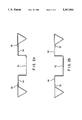
- FIG. 2 shows one of the possible cross-sectional shapes of the rails 1-6.
- a U-shaped rail part 13 is adjoined to the right and to the left by in each case one horizontal rail part 14.
- the end region of the horizontal rail part 14 is in each case bent downward to form a triangle with an attachment tab 15.
- the attachment tab 15 can in this case be arranged as desired above (FIG. 2a) or below (FIG. 2b) the horizontal rail part 14.
- the attachment tabs 15 are firmly connected to the horizontal rail part 14 by pressure joints. There is thus produced at the outer edges of the rails 1-6 a closed hollow body of conical cross-section. Instead of a triangular cross-section there can also be provided any other conical, for instance trapezoidal cross-section.
- the supporting hollow body 7 shown in an exploded view in FIG. 3 comprises partial hollow bodies 9 and 10.
- the latter consist of bent U-shaped metal sheets having two arms 16, 17.
- the side walls 18, 19 are bent inward in U-shape.
- the width of the U-shaped bend 20, 21 corresponds to the width of the U-shaped rail part 13.
- triangular recesses 22 have been cut out corresponding to the cross-section of the transverse rails 4.
- attachment tabs 24, 25 are bent outward at a right angle on top so that the transverse rail 4 can be fitted into the side walls 18, 19 of the supporting hollow body 7.
- the attachment tabs 24 can be developed also as individual angle sheets.
- the arms 16, 17 of the partial hollow bodies 9, 10 are connected by means of the angle sheets 26. In this way there are produced two additional side walls 16, 17, 26 which have recesses 27, 28 at their bottom edge which correspond to the cross-section of the bottom edge rail 1 and the bottom center rail 3.
- the bottom edge rail 1 is arranged on the bottom, the supporting hollow body 7 being placed on the end of the bottom edge rail 1 corresponding to its recesses 27, 28. By means of the angle sheets 26, the bottom edge rail 1 is connected by pressure joints to the supporting hollow body 7.
- the transverse rail 4 is fitted into the upper recesses 22 and the U-shaped bend 20, 21, the transverse rail 4 being in its turn connected to the bent off attachment tabs 24, 25.
- the cover edge rail 2 is attached at a right angle to the transverse rail 4.
- the conical development--triangular in the drawing-- has a centering effect due to its form-locked arrangement in the supporting hollow bodies 7, 8 and thus increases the stability of the sheet metal pallet.
- the supporting hollow bodies 7, 8 described consists in the fact that electronic automation means such as sensors and transmitters can be arranged in the bends 20, 21.
- the supporting hollow bodies 7, 8 may have to be made of non-magnetic material, for instance aluminum.
Abstract
Description
Claims (12)
Applications Claiming Priority (2)
| Application Number | Priority Date | Filing Date | Title |
|---|---|---|---|
| EP92118731.6 | 1992-11-02 | ||
| EP92118731A EP0596146B1 (en) | 1992-11-02 | 1992-11-02 | Four-way pallet made of sheet-metal |
Publications (1)
| Publication Number | Publication Date |
|---|---|
| US5367960A true US5367960A (en) | 1994-11-29 |
Family
ID=8210201
Family Applications (1)
| Application Number | Title | Priority Date | Filing Date |
|---|---|---|---|
| US08/146,760 Expired - Fee Related US5367960A (en) | 1992-11-02 | 1993-11-02 | Four-way sheet metal pallet |
Country Status (14)
| Country | Link |
|---|---|
| US (1) | US5367960A (en) |
| EP (1) | EP0596146B1 (en) |
| JP (1) | JPH06191534A (en) |
| CN (1) | CN1086985A (en) |
| AT (1) | ATE121360T1 (en) |
| CA (1) | CA2109135A1 (en) |
| CZ (1) | CZ211493A3 (en) |
| DE (1) | DE59201982D1 (en) |
| ES (1) | ES2074792T3 (en) |
| FI (1) | FI934845A (en) |
| MX (1) | MX9306819A (en) |
| NO (1) | NO933930L (en) |
| SK (1) | SK110293A3 (en) |
| ZA (1) | ZA937408B (en) |
Cited By (42)
| Publication number | Priority date | Publication date | Assignee | Title |
|---|---|---|---|---|
| US5490465A (en) * | 1993-12-27 | 1996-02-13 | Buckeye Boxes, Inc. | Paperboard/corrugated board pallets and methods for manufacturing such pallets |
| US5687653A (en) * | 1995-03-15 | 1997-11-18 | Bumgarner; Timothy R. | Modular metal pallet |
| US6294114B1 (en) | 1998-08-20 | 2001-09-25 | Scott A. W. Muirhead | Triple sheet thermoforming apparatus, methods and articles |
| US6464191B1 (en) | 1999-03-12 | 2002-10-15 | Warren Gerber | Skid for supporting loads |
| US6661339B2 (en) | 2000-01-24 | 2003-12-09 | Nextreme, L.L.C. | High performance fuel tank |
| US6749418B2 (en) | 1998-08-20 | 2004-06-15 | Scott A. W. Muirhead | Triple sheet thermoforming apparatus |
| US6769367B2 (en) * | 1999-08-19 | 2004-08-03 | Protechna S.A. | Pallet with a base plate and legs of metal |
| US20040168618A1 (en) * | 2000-04-11 | 2004-09-02 | Muirhead Scott Arthur William | Thermoformed platform |
| US20050178299A1 (en) * | 2004-02-17 | 2005-08-18 | Earl Rasmussen | Metal pallet structure |
| US6943678B2 (en) | 2000-01-24 | 2005-09-13 | Nextreme, L.L.C. | Thermoformed apparatus having a communications device |
| US20050237184A1 (en) * | 2000-01-24 | 2005-10-27 | Scott Muirhead | RF-enabled pallet |
| WO2006062288A1 (en) * | 2004-12-10 | 2006-06-15 | Samjung Industries Co., Ltd | Iron pallet, method of manufacturing the same, and intermediate support for the same |
| WO2005037687A3 (en) * | 2003-10-14 | 2006-06-22 | Ayyakannu Mani | Pallets |
| US20060144734A1 (en) * | 2002-10-23 | 2006-07-06 | Baker Gerald L | Bulk bag and rigid fork lift tine receiving member combination |
| US20060175218A1 (en) * | 2005-02-07 | 2006-08-10 | Mctavish Gordon | Bulk bag handling assembly |
| US20060196394A1 (en) * | 2003-10-15 | 2006-09-07 | Bailey Alexander W M | Pallet |
| KR100679845B1 (en) | 2005-07-14 | 2007-02-07 | 주식회사 삼정산업 | Steel Pallet by Press-bonding |
| US20070245932A1 (en) * | 2006-04-24 | 2007-10-25 | Worthington Steelpac Systems | Metal pallet |
| US20080053342A1 (en) * | 2000-04-11 | 2008-03-06 | Nextreme, L.L.C. | Fire resistant plastic pallet with low frequency resistivity |
| US20080202391A1 (en) * | 2004-12-06 | 2008-08-28 | Roberto Pisano | Pallet for Storing and Transporting Goods |
| US20090025615A1 (en) * | 2005-01-15 | 2009-01-29 | Alpallett Co., Ltd. | pallet |
| US20090095205A1 (en) * | 2007-10-16 | 2009-04-16 | Morris Gary W | Plastic pallet system |
| US20090297305A1 (en) * | 2008-05-30 | 2009-12-03 | Bob Autrey | Material handling device |
| US20100107936A1 (en) * | 2006-06-06 | 2010-05-06 | Roberto Pisano | Pallet for storing and transporting goods |
| US20110192327A1 (en) * | 2007-11-07 | 2011-08-11 | Claes Nordstrom | Loading pallet |
| US8077040B2 (en) | 2000-01-24 | 2011-12-13 | Nextreme, Llc | RF-enabled pallet |
| WO2012012363A2 (en) * | 2010-07-19 | 2012-01-26 | Alx Pallet Systems, Llc | Metallic pallet with improved corner construction |
| US20120260832A1 (en) * | 2011-04-13 | 2012-10-18 | Linares Miguel A | Pallet construction with multi surface bonding plasticized spray |
| US8347794B2 (en) | 2000-04-11 | 2013-01-08 | Nextreme, Llc | Fire resistant pallet |
| US8464647B1 (en) * | 2011-09-20 | 2013-06-18 | Frank Chernek | Plastic pallet |
| US8863674B2 (en) * | 2011-08-18 | 2014-10-21 | Unitload Pty Ltd | Load bearing structure |
| WO2015070333A1 (en) * | 2013-11-13 | 2015-05-21 | Palac Industries Inc. | Material handling pallet |
| US20150274358A1 (en) * | 2012-09-17 | 2015-10-01 | Edgar Vargas Hidalgo | Configurable, detachable and recyclable pallet |
| US20160207663A1 (en) * | 2013-08-23 | 2016-07-21 | Roberto Pisano | Metal pallet with assemblable components |
| US20170225826A1 (en) * | 2014-08-08 | 2017-08-10 | Suzhou Pica Aluminum Industry Ltd. | Assembled and combined pallet |
| US10011390B2 (en) * | 2014-12-22 | 2018-07-03 | Sangjin Arp Co., Ltd. | Prefabricated pallet |
| CN110015486A (en) * | 2019-04-22 | 2019-07-16 | 东莞市林格储物包装有限公司 | Hollow metal foot pier and its manufacturing method |
| US11136165B1 (en) * | 2020-03-16 | 2021-10-05 | Big 3 Precision Products, Inc. | Modular shipping base |
| US11242173B2 (en) | 2019-10-21 | 2022-02-08 | Livonia Tool & Laser | Metal pallet |
| US20230071977A1 (en) * | 2019-12-09 | 2023-03-09 | Engchoon Low | Assembling component having locking mechanism |
| US11702244B2 (en) | 2019-10-21 | 2023-07-18 | Michael Rickabaugh | Metal pallet |
| EP4230546A1 (en) * | 2022-02-16 | 2023-08-23 | Lupato S.r.l. | Metal profile and pallet comprising said metal profile |
Families Citing this family (6)
| Publication number | Priority date | Publication date | Assignee | Title |
|---|---|---|---|---|
| JP4739043B2 (en) * | 2006-02-08 | 2011-08-03 | 東邦シートフレーム株式会社 | Metal pallet and manufacturing method thereof |
| DE102006035692A1 (en) | 2006-07-28 | 2008-01-31 | Dieter Meskendahl | pallet |
| DE102008016686A1 (en) * | 2008-04-01 | 2009-10-08 | Krones Ag | Pallet for supporting and transporting bottle, has sensor device arranged on corner region of base plate and outputting signal representing characteristic of force applied on corner region by packaged goods |
| KR200476884Y1 (en) * | 2012-12-14 | 2015-04-15 | 이유구 | Cargo for the palette panel products with packing box add-assembling structures |
| DE202014104130U1 (en) | 2014-09-03 | 2014-09-09 | Storemaster Gmbh & Co. Kg | palette |
| WO2022175859A1 (en) * | 2021-02-19 | 2022-08-25 | Roberto Pisano | Profiled element for a metal pallet, assembly and metal pallet |
Citations (10)
| Publication number | Priority date | Publication date | Assignee | Title |
|---|---|---|---|---|
| US2306752A (en) * | 1940-03-02 | 1942-12-29 | Union Metal Mfg Co | Sheet metal pallet construction |
| US2692107A (en) * | 1952-12-03 | 1954-10-19 | Reynolds Metals Co | Industrial pallet |
| US3616766A (en) * | 1969-09-23 | 1971-11-02 | Follansbee Steel Corp | Metal pallet |
| US4112854A (en) * | 1977-10-07 | 1978-09-12 | Pitchford Peter R | Metal pallet |
| US4145976A (en) * | 1977-03-31 | 1979-03-27 | Extrados Company Limited | Pallet construction |
| EP0015576A1 (en) * | 1979-03-09 | 1980-09-17 | Hermann Schleicher GmbH & Co. Maschinenfabrik | Pallet |
| US4485744A (en) * | 1982-07-19 | 1984-12-04 | Tokyo Shibaura Denki Kabushiki Kaisha | Metal pallet |
| US4714026A (en) * | 1985-04-17 | 1987-12-22 | Honda Giken Kogyo Kabushi Kaisha | Pallet for material handling |
| DE4114888A1 (en) * | 1991-05-07 | 1993-01-28 | Schleicher Sigrid | Load handling pallet assembly - is made from corrugated strips with hollow sections for extra strength |
| US5211117A (en) * | 1991-09-11 | 1993-05-18 | Lorin Industries, Inc. | Pallet assembly |
Family Cites Families (1)
| Publication number | Priority date | Publication date | Assignee | Title |
|---|---|---|---|---|
| FR1593363A (en) * | 1968-11-13 | 1970-05-25 |
-
1992
- 1992-10-12 SK SK1102-93A patent/SK110293A3/en unknown
- 1992-11-02 ES ES92118731T patent/ES2074792T3/en not_active Expired - Lifetime
- 1992-11-02 AT AT92118731T patent/ATE121360T1/en not_active IP Right Cessation
- 1992-11-02 EP EP92118731A patent/EP0596146B1/en not_active Expired - Lifetime
- 1992-11-02 DE DE59201982T patent/DE59201982D1/en not_active Expired - Fee Related
-
1993
- 1993-10-06 ZA ZA937408A patent/ZA937408B/en unknown
- 1993-10-08 CZ CZ932114A patent/CZ211493A3/en unknown
- 1993-10-15 JP JP5280696A patent/JPH06191534A/en active Pending
- 1993-10-25 CA CA002109135A patent/CA2109135A1/en not_active Abandoned
- 1993-10-29 NO NO933930A patent/NO933930L/en unknown
- 1993-11-02 FI FI934845A patent/FI934845A/en not_active Application Discontinuation
- 1993-11-02 US US08/146,760 patent/US5367960A/en not_active Expired - Fee Related
- 1993-11-02 CN CN93119821A patent/CN1086985A/en active Pending
- 1993-11-03 MX MX9306819A patent/MX9306819A/en unknown
Patent Citations (10)
| Publication number | Priority date | Publication date | Assignee | Title |
|---|---|---|---|---|
| US2306752A (en) * | 1940-03-02 | 1942-12-29 | Union Metal Mfg Co | Sheet metal pallet construction |
| US2692107A (en) * | 1952-12-03 | 1954-10-19 | Reynolds Metals Co | Industrial pallet |
| US3616766A (en) * | 1969-09-23 | 1971-11-02 | Follansbee Steel Corp | Metal pallet |
| US4145976A (en) * | 1977-03-31 | 1979-03-27 | Extrados Company Limited | Pallet construction |
| US4112854A (en) * | 1977-10-07 | 1978-09-12 | Pitchford Peter R | Metal pallet |
| EP0015576A1 (en) * | 1979-03-09 | 1980-09-17 | Hermann Schleicher GmbH & Co. Maschinenfabrik | Pallet |
| US4485744A (en) * | 1982-07-19 | 1984-12-04 | Tokyo Shibaura Denki Kabushiki Kaisha | Metal pallet |
| US4714026A (en) * | 1985-04-17 | 1987-12-22 | Honda Giken Kogyo Kabushi Kaisha | Pallet for material handling |
| DE4114888A1 (en) * | 1991-05-07 | 1993-01-28 | Schleicher Sigrid | Load handling pallet assembly - is made from corrugated strips with hollow sections for extra strength |
| US5211117A (en) * | 1991-09-11 | 1993-05-18 | Lorin Industries, Inc. | Pallet assembly |
Non-Patent Citations (2)
| Title |
|---|
| norm A 5300, Vierweg Flachpalette aus Hols, sterreichisches Normungsinstitut (Austrian Standards Institute), Vienna, Austria, pp. 1 7, 1 Jan. 1981. * |
| Onorm A 5300, Vierweg-Flachpalette aus Hols, Osterreichisches Normungsinstitut (Austrian Standards Institute), Vienna, Austria, pp. 1-7, 1 Jan. 1981. |
Cited By (75)
| Publication number | Priority date | Publication date | Assignee | Title |
|---|---|---|---|---|
| US5490465A (en) * | 1993-12-27 | 1996-02-13 | Buckeye Boxes, Inc. | Paperboard/corrugated board pallets and methods for manufacturing such pallets |
| US5687653A (en) * | 1995-03-15 | 1997-11-18 | Bumgarner; Timothy R. | Modular metal pallet |
| US6294114B1 (en) | 1998-08-20 | 2001-09-25 | Scott A. W. Muirhead | Triple sheet thermoforming apparatus, methods and articles |
| US6749418B2 (en) | 1998-08-20 | 2004-06-15 | Scott A. W. Muirhead | Triple sheet thermoforming apparatus |
| US6464191B1 (en) | 1999-03-12 | 2002-10-15 | Warren Gerber | Skid for supporting loads |
| US6769367B2 (en) * | 1999-08-19 | 2004-08-03 | Protechna S.A. | Pallet with a base plate and legs of metal |
| US9230227B2 (en) | 2000-01-24 | 2016-01-05 | Nextreme, Llc | Pallet |
| US7752980B2 (en) | 2000-01-24 | 2010-07-13 | Nextreme Llc | Material handling apparatus having a reader/writer |
| US6661339B2 (en) | 2000-01-24 | 2003-12-09 | Nextreme, L.L.C. | High performance fuel tank |
| US6943678B2 (en) | 2000-01-24 | 2005-09-13 | Nextreme, L.L.C. | Thermoformed apparatus having a communications device |
| US20050237184A1 (en) * | 2000-01-24 | 2005-10-27 | Scott Muirhead | RF-enabled pallet |
| US8585850B2 (en) | 2000-01-24 | 2013-11-19 | Nextreme, Llc | Thermoformed platform having a communications device |
| US7789024B2 (en) | 2000-01-24 | 2010-09-07 | Nextreme, Llc | Thermoformed platform having a communications device |
| US7804400B2 (en) | 2000-01-24 | 2010-09-28 | Nextreme, Llc | Thermoformed platform having a communications device |
| US7342496B2 (en) | 2000-01-24 | 2008-03-11 | Nextreme Llc | RF-enabled pallet |
| US8077040B2 (en) | 2000-01-24 | 2011-12-13 | Nextreme, Llc | RF-enabled pallet |
| US7948371B2 (en) | 2000-01-24 | 2011-05-24 | Nextreme Llc | Material handling apparatus with a cellular communications device |
| US8210107B2 (en) | 2000-04-11 | 2012-07-03 | Nextreme Llc | Plastic pallet structure |
| US7963235B2 (en) | 2000-04-11 | 2011-06-21 | Nextreme, Llc | Thermoformed platform having a communications device |
| US20080053342A1 (en) * | 2000-04-11 | 2008-03-06 | Nextreme, L.L.C. | Fire resistant plastic pallet with low frequency resistivity |
| US7735430B2 (en) * | 2000-04-11 | 2010-06-15 | Nextreme, Llc | Thermoformed platform |
| US20080066658A1 (en) * | 2000-04-11 | 2008-03-20 | Nextreme L.L.C. | Thermoformed platform having a communications device |
| US20110017106A1 (en) * | 2000-04-11 | 2011-01-27 | Muirhead Scott A W | Plastic pallet structure |
| US7874256B2 (en) | 2000-04-11 | 2011-01-25 | Nextreme, Llc | Fire resistant plastic pallet with low radio frequency resistivity |
| US8347794B2 (en) | 2000-04-11 | 2013-01-08 | Nextreme, Llc | Fire resistant pallet |
| US20040168618A1 (en) * | 2000-04-11 | 2004-09-02 | Muirhead Scott Arthur William | Thermoformed platform |
| US20060144734A1 (en) * | 2002-10-23 | 2006-07-06 | Baker Gerald L | Bulk bag and rigid fork lift tine receiving member combination |
| US7594579B2 (en) | 2002-10-23 | 2009-09-29 | Gerald Lynn Baker | Bulk bag and rigid fork lift tine receiving member combination |
| JP2007508215A (en) * | 2003-10-14 | 2007-04-05 | アヤカヌ マニ | palette |
| US20100218705A1 (en) * | 2003-10-14 | 2010-09-02 | Ayyakannu Mani | Pallets |
| US8336466B2 (en) * | 2003-10-14 | 2012-12-25 | Ayyakannu Mani | Pallets |
| WO2005037687A3 (en) * | 2003-10-14 | 2006-06-22 | Ayyakannu Mani | Pallets |
| US20060196394A1 (en) * | 2003-10-15 | 2006-09-07 | Bailey Alexander W M | Pallet |
| US20050178299A1 (en) * | 2004-02-17 | 2005-08-18 | Earl Rasmussen | Metal pallet structure |
| US20080202391A1 (en) * | 2004-12-06 | 2008-08-28 | Roberto Pisano | Pallet for Storing and Transporting Goods |
| US20090101049A1 (en) * | 2004-12-10 | 2009-04-23 | Hi-Man Lee | Iron pallet, method of manufacturing the same, and intermediate support for the same |
| WO2006062288A1 (en) * | 2004-12-10 | 2006-06-15 | Samjung Industries Co., Ltd | Iron pallet, method of manufacturing the same, and intermediate support for the same |
| US20090025615A1 (en) * | 2005-01-15 | 2009-01-29 | Alpallett Co., Ltd. | pallet |
| US7987798B2 (en) * | 2005-01-15 | 2011-08-02 | Alpallet Co., Ltd. | Pallet members |
| US20060175218A1 (en) * | 2005-02-07 | 2006-08-10 | Mctavish Gordon | Bulk bag handling assembly |
| US8033726B2 (en) | 2005-02-07 | 2011-10-11 | LSI—Lift Systems Incorporated | Bulk bag handling assembly |
| KR100679845B1 (en) | 2005-07-14 | 2007-02-07 | 주식회사 삼정산업 | Steel Pallet by Press-bonding |
| US20070245932A1 (en) * | 2006-04-24 | 2007-10-25 | Worthington Steelpac Systems | Metal pallet |
| US20090205540A1 (en) * | 2006-04-24 | 2009-08-20 | Worthington Steelpac Systems | Metal pallet |
| US20100107936A1 (en) * | 2006-06-06 | 2010-05-06 | Roberto Pisano | Pallet for storing and transporting goods |
| US20110162562A1 (en) * | 2007-10-16 | 2011-07-07 | Paradigm Plastic Products, Llc | Plastic pallet system |
| US8261675B2 (en) | 2007-10-16 | 2012-09-11 | Paradigm Plastic Products, Llc | Plastic pallet system |
| US7926431B2 (en) | 2007-10-16 | 2011-04-19 | Paradigm Plastic Products, Llc | Plastic pallet system |
| US20090095205A1 (en) * | 2007-10-16 | 2009-04-16 | Morris Gary W | Plastic pallet system |
| US20110192327A1 (en) * | 2007-11-07 | 2011-08-11 | Claes Nordstrom | Loading pallet |
| US20090297305A1 (en) * | 2008-05-30 | 2009-12-03 | Bob Autrey | Material handling device |
| WO2012012363A3 (en) * | 2010-07-19 | 2012-05-03 | Alx Pallet Systems, Llc | Metallic pallet with improved corner construction |
| WO2012012363A2 (en) * | 2010-07-19 | 2012-01-26 | Alx Pallet Systems, Llc | Metallic pallet with improved corner construction |
| US20120260832A1 (en) * | 2011-04-13 | 2012-10-18 | Linares Miguel A | Pallet construction with multi surface bonding plasticized spray |
| US8813660B2 (en) * | 2011-04-13 | 2014-08-26 | Miguel A. Linares | Pallet construction with multi surface bonding plasticized spray |
| US8863674B2 (en) * | 2011-08-18 | 2014-10-21 | Unitload Pty Ltd | Load bearing structure |
| US9199764B2 (en) | 2011-08-18 | 2015-12-01 | Unitload Pty Ltd | Load bearing structure |
| US8464647B1 (en) * | 2011-09-20 | 2013-06-18 | Frank Chernek | Plastic pallet |
| US9409674B2 (en) * | 2012-09-17 | 2016-08-09 | Cajas Para Exportación Retornables S.A. | Configurable, repairable, and recyclable cargo pallet |
| US20150274358A1 (en) * | 2012-09-17 | 2015-10-01 | Edgar Vargas Hidalgo | Configurable, detachable and recyclable pallet |
| US20160207663A1 (en) * | 2013-08-23 | 2016-07-21 | Roberto Pisano | Metal pallet with assemblable components |
| US9718579B2 (en) * | 2013-08-23 | 2017-08-01 | Roberto Pisano | Metal pallet with assemblable components |
| WO2015070333A1 (en) * | 2013-11-13 | 2015-05-21 | Palac Industries Inc. | Material handling pallet |
| US9751657B2 (en) | 2013-11-13 | 2017-09-05 | Palac Industries Inc. | Material handling pallet |
| US20170225826A1 (en) * | 2014-08-08 | 2017-08-10 | Suzhou Pica Aluminum Industry Ltd. | Assembled and combined pallet |
| US9926103B2 (en) * | 2014-08-08 | 2018-03-27 | Suzhou Pica Aluminum Industry Ltd | Assembled and combined pallet |
| US10011390B2 (en) * | 2014-12-22 | 2018-07-03 | Sangjin Arp Co., Ltd. | Prefabricated pallet |
| CN110015486A (en) * | 2019-04-22 | 2019-07-16 | 东莞市林格储物包装有限公司 | Hollow metal foot pier and its manufacturing method |
| CN110015486B (en) * | 2019-04-22 | 2023-07-07 | 广东省林格科技集团有限公司 | Hollow metal foot pier and manufacturing method thereof |
| US11242173B2 (en) | 2019-10-21 | 2022-02-08 | Livonia Tool & Laser | Metal pallet |
| US11702244B2 (en) | 2019-10-21 | 2023-07-18 | Michael Rickabaugh | Metal pallet |
| US20230071977A1 (en) * | 2019-12-09 | 2023-03-09 | Engchoon Low | Assembling component having locking mechanism |
| US11952165B2 (en) * | 2019-12-09 | 2024-04-09 | Engchoon Low | Assembling component having locking mechanism |
| US11136165B1 (en) * | 2020-03-16 | 2021-10-05 | Big 3 Precision Products, Inc. | Modular shipping base |
| EP4230546A1 (en) * | 2022-02-16 | 2023-08-23 | Lupato S.r.l. | Metal profile and pallet comprising said metal profile |
Also Published As
| Publication number | Publication date |
|---|---|
| ATE121360T1 (en) | 1995-05-15 |
| NO933930D0 (en) | 1993-10-29 |
| JPH06191534A (en) | 1994-07-12 |
| ZA937408B (en) | 1994-06-21 |
| CZ211493A3 (en) | 1994-05-18 |
| SK110293A3 (en) | 1994-06-08 |
| FI934845A (en) | 1994-05-03 |
| ES2074792T3 (en) | 1995-09-16 |
| NO933930L (en) | 1994-05-03 |
| FI934845A0 (en) | 1993-11-02 |
| EP0596146B1 (en) | 1995-04-19 |
| CA2109135A1 (en) | 1994-05-03 |
| EP0596146A1 (en) | 1994-05-11 |
| MX9306819A (en) | 1995-01-31 |
| DE59201982D1 (en) | 1995-06-01 |
| CN1086985A (en) | 1994-05-25 |
Similar Documents
| Publication | Publication Date | Title |
|---|---|---|
| US5367960A (en) | Four-way sheet metal pallet | |
| US4002000A (en) | Beam construction and method of manufacture | |
| US4240360A (en) | Stackable flat pallet | |
| US5809907A (en) | Pallet assembly | |
| US4424752A (en) | Loading pallet | |
| US6463711B1 (en) | Construction hanger | |
| US2446914A (en) | Pallet construction | |
| US4760682A (en) | Tubular rack beam and method of making same | |
| US6041719A (en) | Material handling pallet | |
| FI69433C (en) | SHOOTBALL AV RAEFFLAD VAOGFORMIG PLAOT | |
| AU708120B2 (en) | Pallet | |
| CA1076496A (en) | Metal pallet | |
| JP2001517184A (en) | Transport equipment | |
| GB2145397A (en) | Freight container for flowable materials | |
| US2501506A (en) | Pallet construction | |
| US7257932B2 (en) | Light weight building material | |
| US4292782A (en) | Sheet metal structural beam | |
| US2306752A (en) | Sheet metal pallet construction | |
| EP0187834B1 (en) | Material handling pallet | |
| US5967353A (en) | Tank container | |
| EP0167545A1 (en) | Beam. | |
| EP0084906B1 (en) | High-strength tubular beam of folded corrugated cardboard | |
| US3160120A (en) | Stackable pallet of pressed sheet material | |
| US4283080A (en) | Flange for a duct | |
| US1875104A (en) | Skid |
Legal Events
| Date | Code | Title | Description |
|---|---|---|---|
| AS | Assignment |
Owner name: SCHLEICHER, GUDRUN, GERMANY Free format text: ASSIGNMENT OF ASSIGNORS INTEREST;ASSIGNOR:SCHLEICHER, HERMANN;REEL/FRAME:006769/0836 Effective date: 19931011 Owner name: SCHLEICHER, BERND, GERMANY Free format text: ASSIGNMENT OF ASSIGNORS INTEREST;ASSIGNOR:SCHLEICHER, HERMANN;REEL/FRAME:006769/0836 Effective date: 19931011 Owner name: SCHLEICHER, STEFAN, GERMANY Free format text: ASSIGNMENT OF ASSIGNORS INTEREST;ASSIGNOR:SCHLEICHER, HERMANN;REEL/FRAME:006769/0836 Effective date: 19931011 Owner name: SCHLEICHER, SIGRID, GERMANY Free format text: ASSIGNMENT OF ASSIGNORS INTEREST;ASSIGNOR:SCHLEICHER, HERMANN;REEL/FRAME:006769/0836 Effective date: 19931011 |
|
| REMI | Maintenance fee reminder mailed | ||
| LAPS | Lapse for failure to pay maintenance fees | ||
| FP | Lapsed due to failure to pay maintenance fee |
Effective date: 19981129 |
|
| STCH | Information on status: patent discontinuation |
Free format text: PATENT EXPIRED DUE TO NONPAYMENT OF MAINTENANCE FEES UNDER 37 CFR 1.362 |