US5371361A - Optical processing system - Google Patents
Optical processing system Download PDFInfo
- Publication number
- US5371361A US5371361A US08/012,289 US1228993A US5371361A US 5371361 A US5371361 A US 5371361A US 1228993 A US1228993 A US 1228993A US 5371361 A US5371361 A US 5371361A
- Authority
- US
- United States
- Prior art keywords
- scanner
- target
- scan volume
- signal
- opto
- Prior art date
- Legal status (The legal status is an assumption and is not a legal conclusion. Google has not performed a legal analysis and makes no representation as to the accuracy of the status listed.)
- Expired - Lifetime
Links
Images


Classifications
-
- G—PHYSICS
- G06—COMPUTING; CALCULATING OR COUNTING
- G06K—GRAPHICAL DATA READING; PRESENTATION OF DATA; RECORD CARRIERS; HANDLING RECORD CARRIERS
- G06K7/00—Methods or arrangements for sensing record carriers, e.g. for reading patterns
- G06K7/10—Methods or arrangements for sensing record carriers, e.g. for reading patterns by electromagnetic radiation, e.g. optical sensing; by corpuscular radiation
- G06K7/10544—Methods or arrangements for sensing record carriers, e.g. for reading patterns by electromagnetic radiation, e.g. optical sensing; by corpuscular radiation by scanning of the records by radiation in the optical part of the electromagnetic spectrum
- G06K7/10821—Methods or arrangements for sensing record carriers, e.g. for reading patterns by electromagnetic radiation, e.g. optical sensing; by corpuscular radiation by scanning of the records by radiation in the optical part of the electromagnetic spectrum further details of bar or optical code scanning devices
- G06K7/10851—Circuits for pulse shaping, amplifying, eliminating noise signals, checking the function of the sensing device
-
- G—PHYSICS
- G02—OPTICS
- G02B—OPTICAL ELEMENTS, SYSTEMS OR APPARATUS
- G02B26/00—Optical devices or arrangements for the control of light using movable or deformable optical elements
- G02B26/08—Optical devices or arrangements for the control of light using movable or deformable optical elements for controlling the direction of light
- G02B26/10—Scanning systems
- G02B26/12—Scanning systems using multifaceted mirrors
-
- G—PHYSICS
- G02—OPTICS
- G02B—OPTICAL ELEMENTS, SYSTEMS OR APPARATUS
- G02B27/00—Optical systems or apparatus not provided for by any of the groups G02B1/00 - G02B26/00, G02B30/00
- G02B27/0075—Optical systems or apparatus not provided for by any of the groups G02B1/00 - G02B26/00, G02B30/00 with means for altering, e.g. increasing, the depth of field or depth of focus
-
- G—PHYSICS
- G06—COMPUTING; CALCULATING OR COUNTING
- G06K—GRAPHICAL DATA READING; PRESENTATION OF DATA; RECORD CARRIERS; HANDLING RECORD CARRIERS
- G06K7/00—Methods or arrangements for sensing record carriers, e.g. for reading patterns
- G06K7/10—Methods or arrangements for sensing record carriers, e.g. for reading patterns by electromagnetic radiation, e.g. optical sensing; by corpuscular radiation
- G06K7/10544—Methods or arrangements for sensing record carriers, e.g. for reading patterns by electromagnetic radiation, e.g. optical sensing; by corpuscular radiation by scanning of the records by radiation in the optical part of the electromagnetic spectrum
- G06K7/10554—Moving beam scanning
- G06K7/10564—Light sources
- G06K7/10584—Source control
-
- H—ELECTRICITY
- H04—ELECTRIC COMMUNICATION TECHNIQUE
- H04N—PICTORIAL COMMUNICATION, e.g. TELEVISION
- H04N1/00—Scanning, transmission or reproduction of documents or the like, e.g. facsimile transmission; Details thereof
- H04N1/04—Scanning arrangements, i.e. arrangements for the displacement of active reading or reproducing elements relative to the original or reproducing medium, or vice versa
Definitions
- the field of the present invention relates generally to optical systems which characterize features on an object including the relative position of features on a target symbol or object. These systems may include but are not limited to bar code scanners and optical character recognition (OCR) systems. More specifically, this invention relates to improvements in such a system which provide benefits such as a greater depth of field, improved probability of a correct scan on the first pass, a reduced need for adaptive thresholding, and a reduction in required dynamic range.
- OCR optical character recognition
- Scan Volume The volume in space adjacent to the window of a scanner over which the scanner can successfully read or recognize a target
- Depth of Field The distance over which a scanner can successfully read or recognize a target, measured in one dimension along the beam propagation path;
- the time domain impulse response of the opto-mechanical subsystem of the scanner is defined as the analog signal which results from scanning the beam over a narrow dark bar or element placed within the scan volume.
- the electrical subsystem it is the response to a pulse at the input of infinitesimal width.
- an optical system it is the image of a point at infinity;
- equalization is defined as the application of a filter to a signal S(z), which has been distorted by some function F(z).
- the equalization filter is designed to compensate for the negative effects of F(z), thus restoring S(z) to nearly its original state.
- the equalization filter can be thought of as the inverse of F(z), that is, 1/F(z).
- the combined effect of F(z) times 1/F(z) is approximately equal to one over some prescribed range.
- the domain of the variable z may be one-dimensional or two-dimensional, and that the equalization need not be perfect to be of practical benefit;
- Constant impulse response scanning system A scanning system in which the opto-mechanical subsystem impulse response is uniform enough throughout the scan volume to achieve the desired goal of equalizing the system with a single, time-invariant filter, without under- or over-compensating at any one target position within the scan volume;
- Amplitude modulation depth The difference between the signal amplitude for a dark feature and the signal amplitude for a light feature;
- Beam Waist The point along the beam axis at which the width of the beam intensity profile is minimum, measured parallel to the direction of spot motion.
- the examples and figures discussed herein assume a Gaussian intensity profile, for which the waist location is well defined, but useful embodiments of the subject invention can also be implemented with other intensity profiles.
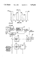
- FIG. 1 An opto-mechanical system configured for use in a bar code scanner is illustrated in FIG. 1.
- the system comprises light source 1 (typically a laser), focusing optics 2, fold mirror 2a, and scanning mirror 3.
- the system may also include folding and/or pattern generation mirrors (not shown).
- Light beam 5 is emitted from light source 1, whereupon it is directed to travel along an optical path.
- Focusing optics 2 are placed along the optical path, and are utilized to focus the beam 5, to provide a minimum diameter at point 6, known as the beam waist.
- a scanning mirror 3 (illustrated as a facet wheel which is typically in the shape of a polygon) is placed along the optical path, and caused to rotate by a motor (not shown) around center of rotation point 3a.
- the light source 1, focusing optics 2, and scanning mirror 3 are typically placed in the interior of a housing having a window 4, through which the beam is directed to emerge from the housing.
- the window 4 is configured with appropriate transmission characteristics to enable the beam 5 to exit the interior of the housing with minimal loss.
- the scanner is aimed towards a target (e.g., a bar code symbol), with the scanning mirror 3 (and pattern generation mirrors if present) operating to scan the beam 5 over the target in a predetermined pattern.
- a collection subsystem (not shown) which typically includes a photodetector, then collects at least some of the light reflected or scattered off the target, and the photodetector produces an analog signal having an amplitude determined by the intensity of the collected light. Since more light reflects off lighter areas than dark areas (or elements), the amplitude of the analog signal will vary accordingly as the beam 5 scans the target.
- the scanner also includes a signal processing subsystem (not shown) for digitizing the analog signal and providing a digital signal, where the width of and spacing between the pulses in the digital signal corresponds to the width of the dark and light areas (e.g., bars/spaces or elements) making up the target.
- the digital signal is then decoded by a decoder (not shown), either located within the scanner, or located externally to it.
- the outer bounds of the scan volume are typically situated on either side of the beam waist 6.
- the beam diameter increases as a function of the distance from the beam waist 6. This is due to fundamental diffraction effects. As the beam diameter increases, the ability to successfully read targets, especially those with closely spaced elements, diminishes, and eventually is lost. Performance at the outer extremes of the scan volume is further limited by collected optical power, which decreases approximately as the square of the distance from the scanner. Together these factors determine the outer bounds of the scan volume.
- FIG. 2a illustrates an analog signal 10 which results from passing a laser beam 9 across a target 11 (in this example a bar code symbol) in the indicated scanning direction.
- the diameter of the beam 9 is no larger than the smallest dark or light element in the target symbol (identified with width t 1 ).
- the amplitude modulation depth of the portion of the analog signal which derives from the more closely spaced elements 12a, identified with reference numeral 12b in the figure is about the same as the amplitude modulation depth of the portion of the analog signal which derives from the less closely spaced elements 13a, identified with reference numeral 13b in the figure.
- FIG. 2b illustrates the effect of scanning the same target with a beam 9' of larger diameter.
- FIGS. 2c and 2e illustrate the relationship of this larger beam 9' to the width of the narrower (t 1 ) and wider (t 2 ) bars in the example. As illustrated, the diameter of the beam 9' is larger than the width of the more closely spaced elements 12a' making up the target.
- the amplitude modulation depth of the lower portion 12b' of the analog signal which derives from the more closely spaced elements 12a' is less than that of the higher portion 13b' of the analog signal which derives from the less closely spaced elements 13a'. This effect occurs since the beam 9' is too large to wholly fit within the confines of the more-closely spaced elements 12a', but not the less-closely spaced elements 13a'. Since the total energy contained in both the large and small spots is the same, the amplitude modulation depth of the analog signal will be determined by the amount of overlap between a spot and an element: Comparing three situations, when a narrow element 12a' is encountered by a larger spot 9', a situation illustrated in FIG.
- the amount of overlap (indicated by cross-hatching in the figure) is less than the amount of overlap between a smaller spot 9 and a narrow element 12a, a situation illustrated in FIG. 2d, and the amount of overlap between a larger spot 9' and a wider element 13a', a situation illustrated in FIG. 2e. Therefore, the amplitude modulation depth of the analog signal in the first situation will be less than that for the latter two situations.
- an optical scanner comprising an opto-mechanical system for providing a beam, directing the beam along an optical path to a target situated within a desired scan volume, and scanning the beam over the target in a predetermined pattern; a collection system for collecting light reflected from the target and converting it into an electrical current; an electrical system operatively coupled to the collection system for forming a signal having an amplitude modulation depth at least partly determined by the intensity of the collected light; a digitizer for generating a digital signal which assumes one state when the beam passes over a dark area or element and another state when the beam passes over a light area or element; and a decoder for translating element widths into character or other information.
- the opto-mechanical system is configured to direct the beam into the scan volume such that at least one parameter associated with the opto-mechanical system, which would otherwise vary along the beam axis within the scan volume, is held approximately constant, thereby improving the capability of the electrical system to compensate for unwanted variations in the amplitude modulation depth of the signal over the scan volume (e.g., through the use of a single, time-invariant equalizer).
- the parameter which is held approximately constant is the width of the time domain impulse response of the opto-mechanical scanning system. This result is achieved by positioning the beam waist appropriately so that the beam spot size increases approximately linearly as distance from the scanner increases. Since the spot velocity in this embodiment also increases approximately linearly along the beam axis within the scan volume, the ratio of the two, which represents the width of the time domain impulse response, is held approximately constant throughout the scan volume.
- the diameter of the beam and the linear spot velocity are the parameters which are held approximately constant.
- the pulse width of the system temporal impulse response is approximately constant regardless of distance from the scanner along the beam axis.
- the parameter which is held approximately constant is the beam power.
- the opto-mechanical system described above is replaced by an imaging system, wherein the target plane is imaged upon an optical element having an array of pixels which are scanned by electronic means, such that the temporal impulse response of the imaging system is held approximately constant regardless of distance between the optical element and the target.
- FIG. 1 is a schematic diagram of an opto-mechanical system for use in a bar code scanner
- FIGS. 2a-2e are diagrams illustrating the variations in the amplitude modulation depth of the analog signal which derive from variations in spot size;
- FIG. 3 is a graph illustrating variations in the step response of the opto-mechanical system which can occur along the beam axis within the scan volume;
- FIGS. 4a-4b are graphs illustrating effects of overcompensating for variations in spot size
- FIG. 5 is a graph illustrating how overcompensating can distort the resultant differentiated signal
- FIG. 6 is a graph illustrating how overcompensating can lead to false transitions in the resultant digital signal
- FIG. 7a is a series of plots of spot diameter vs. distance along the beam path in an exemplary scanner, where the location and beam diameter at the beam waist is varied;
- FIG. 7b is a series of plots of the temporal impulse response pulse width of the opto-mechanical system vs. distance along the beam path in an exemplary scanner when the beam waist is situated at the scanning mirror;
- FIG. 7c is a series of plots of the temporal impulse response pulse width of the opto-mechanical system vs. distance along the beam path in an exemplary scanner when the beam waist is situated at a predetermined distance downstream from the scanning mirror;
- FIG. 8 is a block diagram of an electrical system which includes a compensation, or equalization, subsystem
- FIG. 9 is a detailed circuit diagram of the system of FIG. 8, excluding the preamplifier (PA);
- FIGS. 10a-10c are graphs illustrating overequalized asymmetric (a), overequalized symmetric (b), and properly-equalized symmetric (c) overall system time domain step responses;
- FIGS. 11a, 11b, and 11c are graphs illustrating the normalized time domain impulse response, the frequency domain magnitude response, and the frequency domain group delay, respectively, of an approximately symmetric equalization and/or signal processing filtering system;
- FIG. 12 is a diagram illustrating the relative orientation of scan lines in an exemplary embodiment of a fixed scanner, as imaged onto the plane of the window;
- FIG. 13 is a graph illustrating the power profile of the scan lines of FIG. 12;
- FIG. 14 is a circuit diagram illustrating circuitry for achieving at least partial compensation of beam power variation across the scan lines of FIG. 12;
- FIGS. 14a-14c illustrate exemplary optical encoding wheels for use in alternate embodiments in which compensation for beam power variation across the scan lines of FIG. 12 is achieved.
- FIGS. 15a and 15b are graphs illustrating target reflectance, modulation depth of the analog signal, and the second (time) derivative of the modulation depth curve for a system with and without linear phase equalization, respectively.
- FIG. 16 illustrates an alternate embodiment utilizing an imaging device.
- variable gain amplifier whose function, as described, is to compensate for the effects of a large spot size, will only imperfectly perform this function within the scan volume. Specifically, at some locations along the beam axis within the scan volume, the variable gain amplifier will overcompensate (i.e., amplify the high frequency components of the analog signal too much); while at other locations within the scan volume, the amplifier will undercompensate (i.e., not amplify the high frequency components enough).
- overcompensation is to introduce under-shoot and over-shoot into the analog signal. During digitization, this distortion can cause erroneous generation of digital pulses, which can lead to improper decoding of the bar code target.
- the effect of undercompensation is that the signal amplitude modulation depth is reduced as the element (e.g., bar) width becomes small relative to the spot diameter, and, therefore, the target becomes unreadable. Again, improper digitization and decoding of the signal can result.
- step response 14- which is a graph of the analog signal generated by passing the laser beam spot over a dark-to-light transition--of the opto-mechanical system at the location indicated with reference numeral 6' in FIG. 1.
- the relationship between the impulse response and the step response is that the former is the time derivative of the latter.
- a characteristic of the step response at location 6' is that the rise time (which correlates to the width of the impulse response) is slow because of the increased diameter of the spot size at that point compared with that at the beam waist.
- the variable gain filter is applied to this signal, the result is a signal with a faster rise time, as indicated by signal 15 in FIG. 3.
- the step response of the conventional opto-mechanical system at location 6 of the scan volume which is identified with reference numeral 14' in FIG. 4a, will have a faster rise time than the step response at location 6'.
- This effect is due to the fact that, as the target moves toward the scanner between location 6' and 6 along the beam axis, the spot size decreases at a faster rate than the spot velocity, such that the duration of the step response is reduced. Therefore, when this signal is passed through the variable gain filter, the effect is to introduce distortion, in the form of under-shoot and over-shoot, into the signal.
- the distortion resulting from overcompensation can, as noted previously, lead to improper digitization of the analog signal.
- the reason is that the signal processing subsystem--that portion of the scanner that normally performs the digitization function--typically operates by detecting transitions in the analog signal (or a derivative thereof) across a known threshold level.
- a signal processing subsystem is described which detects zero crossings of a second derivative of the signal, which are qualified only when the first derivative of the signal exceeds a threshold voltage.
- the distortion introduced by overcompensation may erroneously cause the second derivative to reach zero, and if the first derivative amplitude is sufficiently high, may lead to false transitions in the resultant digital signal.
- FIG. 5 shows the derivative of the overequalized signal 15' of FIG. 4b
- FIG. 6 shows the resultant digital signal.
- two false transitions 17 and 17' respectively, have been improperly introduced into the digital signal.
- an optical scanner in which the opto-mechanical portion thereof is configured such that the width of the time domain impulse response remains approximately constant over the desired scan volume. Doing so enables equalization for large spot sizes to be accomplished while avoiding the problems of overcompensation and undercompensation at certain points within the scan volume.
- d spot (z) beam diameter (or spot size)
- the beam diameter increases approximately linearly as a function of distance.
- V z the linear spot velocity at the location z along the beam path.
- the ratio of the beam diameter to the linear spot velocity should remain approximately constant along the beam axis over the scan volume.
- the time domain impulse response pulse width of prior art devices varies widely over the scan volume.
- the pulse width in the scan volume of such a prior art device might vary 160% from its value at the window.
- the time domain impulse response pulse width remains approximately constant, generally varying less than ⁇ 25% (with 10-20% being a preferred range) over the useful scan volume, relative to its value at the window. Operating within this range, the desired goal of equalizing the system with a single, time-invariant filter while effectively eliminating under-compensation or over-compensation, typically becomes achievable.
- One method in which the time domain impulse response pulse width can theoretically be held approximately constant is by positioning the beam waist 6 (reference FIG. 1) at the optical center of rotation 3a of the scanning mirror 3 (hereinafter referred to as "center of rotation").
- center of rotation By positioning the beam waist 6 in this manner, the spot size of the beam will diverge throughout the scan volume, with the diameter approaching an asymptote which crosses through the intersection of the beam axis and the beam waist.
- the spot diameter becomes approximately proportional to the distance from the beam waist.
- the linear spot velocity will also increase linearly, proportional to the distance from the center of rotation. Since the numerator and denominator in the aforementioned equation (2) are both increasing approximately linearly, the ratio--which, as stated, represents the pulse width of the impulse response--will remain approximately constant.
- the spot size will actually be larger within the scan volume than would otherwise be the case. Therefore, given the previously-discussed disadvantages of a larger spot size (i.e., reduced amplitude modulation depth over narrow element portions, need to compensate therefore, and resulting overcompensation or undercompensation at some points within the scan volume using existing methods), it would appear disadvantageous to place the beam waist 6 in such a position (i.e., at the center of rotation). However, as this positioning provides for a near constant impulse response width, more uniform equalization throughout the scan volume is realized despite the larger spot size. Consequently, the results achieved by positioning the beam waist in this manner are unexpected.
- the offset placement of the beam waist from the center of rotation allows the beam waist location to be maintained within the scanner housing (i.e., the preferable beam waist position being prior to the scanner window along the beam path) though the beam waist does not absolutely have to be placed within the scanner housing. Consequently, the time domain impulse response width remains approximately constant (though constancy is somewhat diminished compared to that realized with no offset) at points beyond the window, within the scan volume, while the diameter at any particular point within the scan volume is smaller than if the beam waist were placed at the exact center of rotation of the scanning mirror.
- These curves were plotted assuming the light source is a laser emitting at a wavelength of 670 nanometers, and a facet wheel rotation rate of 5500 RPM. It should be appreciated that these curves could change with different assumptions. For all of these curves, it is assumed that the window--through which the beam exits the housing--is appropriately situated along the z-axis so that the time domain impulse response width of the opto-mechanical system is approximately constant thereafter.
- FIG. 7a this figure illustrates a family of curves, identified with numerals 18a-18h, where each curve in the family corresponds to a particular value of the beam diameter at the beam waist, and plots the beam diameter as a function of z, the distance along the beam path.
- the correspondence between each of these curves and the beam diameter at the beam waist is given by the following table:
- the correspondence between each of these curves and the beam diameter at the beam waist is given by the following table:
- FIG. 7c illustrates a family of curves, identified with numerals 20a-20d, where each curve in the family corresponds to a particular value of the beam diameter at the beam waist, and plots the temporal impulse response width as a function of z, the distance along the beam path, in the case where the beam waist is situated about 12.5 in. (31.75 cm) downstream from the optical center of rotation of the scanning mirror along the beam path.
- the correspondence between each of these curves and the beam diameter of the beam waist is given by the following table:
- FIGS. 7a-7c illustrate the tradeoff between constancy and absolute magnitude of the temporal impulse response pulse width, and, correspondingly, spot size. Maintaining a constant temporal response pulse width throughout the scan volume (for example, curve 19a of FIG. 7b) insures that the system may theoretically be equalized exactly regardless of target position along the z axis. However, the beam size in this case (curve 18a in FIG. 7a) is very large for large z.
- the beam waist may be positioned within the housing (i.e. prior to the scanner window).
- the actual scanner window location is dictated substantially by physical parameters, but there is a certain amount of flexibility in these physical parameters.
- a system may readily be designed locating the beam waist at various locations, including (1) within the scanner housing (that is, at a position on the beam axis prior to or at the scanner window), (2) at the scanner window, or (3) near the scanner window [e.g. within ⁇ 1/2 in (1.27 cm) thereof].
- a primary advantage of an approximately constant impulse response is the improved ability to electrically reduce the effective pulse width, making it possible to accurately render small target features over a larger range.
- a secondary advantage is that the benefits of a larger spot, such as the ability to filter out paper noise, are retained along paths other than the path over which equalization is performed (i.e., the direction of spot motion along the target).
- This secondary advantage is particularly important since, along the vertical edge of an element (e.g., a bar), noise can result from what is typically a somewhat jagged and ill-defined edge. A large spot can filter out this noise since the noise along the edge is effectively integrated over the spot area.
- equalization is performed only in one dimension, along the scanning path (i.e., the path the spot traverses over the target), which is typically different from the vertical edge of an element, a large spot will effectively filter out this noise in this embodiment.
- a large spot may also be beneficial since it will average out some of the speckle noise introduced by the laser.
- speckle a non-linear effect
- equalization a linear operation
- Exemplary of such an implementation is one in which a one-dimensional or two-dimensional image of a target is captured, processed, and scanned "virtually" by a computer program or the like which causes a "virtual" spot to traverse the image of the target, rather than physically scanning the target itself, thus providing sufficient flexibility such that the scanning (and hence equalization) path can be arbitrarily chosen to be as different as necessary from the path over which it is desired to average out noise.
- beam parameters other than the temporal impulse response pulse width are held approximately constant over the scan volume to improve the ability of equalizing for the effect of a large spot size.
- Other techniques may also be utilized to maintain the approximate constancy of the temporal impulse response pulse width over the scan volume.
- the time domain impulse response width is made to remain approximately constant by holding the beam diameter and the spot velocity both approximately constant over the desired scan volume.
- the distance between the scanner and target can be automatically determined, such as, for example, by utilizing the focusing error-sensing optical subsystem described in co-pending U.S. patent application Ser. No. 07/844,278, Reddersen et al., filed Mar. 2, 1992, herein incorporated by reference. Once this distance is determined, this distance value is utilized to adjust the rotational speed of the scanner motor so that the linear spot velocity remains approximately constant throughout the scan volume.
- the former objective can be achieved by using a beam which has an approximately constant diameter over the scan volume.
- One way such a beam can be formed is through proper utilization of an optical element known as an axicon, optionally in conjunction with a slit to eliminate the outer concentric rings generated by the axicon, such as is discussed in U.S. Pat. No. 5,080,456, herein incorporated by reference.
- an optical element known as an axicon
- a slit to eliminate the outer concentric rings generated by the axicon
- the parameter which remains approximately constant is the beam power.
- one manner of implementation is to scan and process one-dimensional or two-dimensional images of the target by simply scanning a laser beam across the target in a one-dimensional or two-dimensional pattern, respectively, forming an electrical representation of the collected signal, similar to the implementation discussed in European Publication No. 0 384 955 herein incorporated by reference.
- a one-dimensional or two-dimensional image of the target is obtained directly by utilizing a one-dimensional or two-dimensional imaging device such as a CCD, video camera, or the like, similar to that described in European Publication No. 0 385 478 also incorporated herein by reference.
- Imaging devices using lenses such as video cameras (vidicons), CCD cameras and the like, are not well suited to edge detection applications where large depth-of-field is required, because the range of focus is relatively short. Automatic focussing is one means to alleviate this difficulty, but an accurate target distance measurement means, and a means to alter focus location, are required.
- FIG. 16 depicts an imaging system 90 for use in capturing an image of the target 92.
- a light source 94 and optics 96 are configured such that the light is incident on the target 92 and may be detected by imaging device 98 (e.g., a CCD).
- An optical element 100 is utilized to enhance focus characteristics.
- the optical element 100 is a "soft-focus" lens, which for purposes of this disclosure is defined to be a lens with nearly constant optical impulse response (known as the "point spread function") as a function of object distance.
- Examples of this type include commercially available axicon-like imaging lenses, under-corrected or over-corrected (spherically aberrated) lenses, and lenses with chromatic aberration used with polychromatic illumination.
- quality of mid-field focus is sacrificed slightly to achieve near-invariance of focus throughout the scan volume. This invariance in turn allows the use of a single, time-invariant equalizer without risk of under-equalization or over-equalization for certain imager-to-target distances.
- An imaging device which may, for example, comprise an array of photodetectors, can be used to both sense and electronically scan an image.
- An array of photodetectors could represent the image in pixel-like manner, and, by individually addressing each pixel (e.g., photodetector), the image, once captured, could be electronically scanned simply by reading out the pixels in an order determined by a desired scan pattern.
- This approach eliminates the need for intermediate video image storage, such as a frame buffer.
- a soft-focus lens could be used with a device of this type, in the manner described in the previous paragraph, to increase the volume over which small features can be accurately rendered.
- Other similar implementations are possible using conventional CCD, CID or vidicon sensing devices with frame storage to allow pixels to be individually addressed.
- the equalization can be applied in real time to the signal as it emerges from the image sensor.
- Sensors are available that provide both one-dimensional (raster) signals as well as two-dimensional signals. These signals can be equalized by one-dimensional or two-dimensional filter functions in accordance with the teachings of this invention.
- FIG. 8 A block diagram of a first embodiment of such a system is shown in FIG. 8.
- the system comprises a signal processing subsystem 30 (for amplifying and filtering the analog signal) and an equalization subsystem 29 (for equalizing to reduce temporal response pulse width).
- the signal processing subsystem 30 comprises a pre-amplifier 24, a bandpass filter 25, and a low-pass filter 26.
- the equalization subsystem 29 comprises an high-pass filter 27 and a sum/gain stage 28.
- a differentiator and gating and thresholding electronics are also utilized to convert filtered data into a serial digital data stream; in this embodiment these elements are located downstream from the sum/gain stage 28.
- the bandpass filter 25 comprises resistor 2501, capacitor 2502, resistor 2503, capacitor 2504, resistor 2505, and operational amplifier 2506, all coupled together as shown.
- the low-pass filter 26 in this embodiment comprises resistor 2601, capacitor 2602, resistor 2603, operational amplifier 2604, capacitor 2605, and resistor 2606, all coupled together as shown.
- the high-pass filter 27 in this embodiment comprises capacitor 2701, capacitor 2702, capacitor 2703, resistor 2704, operational amplifier 2705, and resistor 2706, all coupled together as shown.
- the sum/gain stage 28 in this embodiment comprises potentiometer 2801, resistor 2802, capacitor 2803, capacitor 2804, resistor 2805, operational amplifier 2806, resistor 2807, capacitor 2808, resistor 2809, and capacitor 2810, all coupled together as shown.
- the signal processing subsystem 30 is advantageously a derivative-based signal processing system in which the bandpass filter 25 forms the first derivative of the analog signal, and the low-pass filter 26 filters out unwanted high frequency noise.
- a second high pass filter (not shown) and gating and threshold electronics (not shown) located downstream of the summation gate function to form the second derivative of the analog signal arid to form a digital signal by creating digital transitions at zero crossings of the second derivative signal when the first derivative exceeds a predetermined threshold level. Additional details regarding the design and operation of such a derivative based signal processing system are available in U.S. Pat. No. 4,000,397 and pending U.S. patent application Ser. No. 07/786,290, (previously incorporated herein by reference).
- equalization subsystem 29 the function of this subsystem is to amplify the high-frequency components of the analog signal (or a derivative thereof) to compensate for the effect of large spot size.
- equalization is performed on the first derivative of the analog signal, although it should be appreciated that embodiments are possible where equalization is performed directly on the analog signal itself.
- the width of the combined electro-optical system impulse response must be sufficiently small to ensure that adjacent edges do not interfere. This requirement is met by making the spot diameter (as imaged on the target) as small and as consistent as possible throughout the scan volume, and then increasing the magnitude of the high frequency response until the smallest target feature is rendered accurately.
- the phase response of the electro-optical system must be approximately linear (i.e. the group delay response must be approximately constant) over the passband. This constant group delay insures that all edges will be delayed by an equal amount as they pass through the electrical system, regardless of position with respect to neighboring edges.
- the beam cross section is symmetrical.
- a low-pass filter polynomial having linear or nearly linear phase response but without high frequency boost, is used.
- Appropriate examples of such filters include the Bessel, Linear Phase with Equiripple Error, and Transitional Gaussian families. Additional information on the design of such filters is provided in the book entitled "Electronic Filter Design Handbook", Arthur B. Williams, published 1981 by McGraw-Hill, Inc., herein incorporated herein by reference.
- the signal processing subsystem 30 is designed in such a way that the poles of its transfer function match those of the desired filter polynomial.
- the electrical system has linear or nearly linear phase response in its passband without the equalization subsystem 29 in place.
- the high pass filter 27 is designed such that its poles match those of the low pass filter 26. Matching the pole locations of these two filters insures that the composite transfer function will have the same phase response as the low pass filter 26 alone.
- an appropriate parallel high pass filter would have the following transfer function: ##EQU4##
- the overall system of FIG. 8 is configured to have a symmetric time domain impulse response. Since a filter having a symmetrical time domain impulse response also has a linear phase response and constant group delay in the passband, these terms can be used interchangeably.
- the equalization filter disclosed in European Publication No. 0 433 593 is not disclosed as being symmetric.
- the disadvantage of an asymmetric filter is that it delays high frequencies to a different degree than low frequencies, which can cause pattern-dependent distortion of relative edge positions.
- the linear phase equalization filter is implemented as an approximation to an inverse filter.
- the filtering (or smoothing) caused by the convolution of the printed features with the scanning spot can be compensated for by the application of a filter that has a transfer function equal to the inverse of the transfer function of the spot.
- This operation is commonly called de-convolution, and may be performed on one-dimensional or two-dimensional signals (images).
- the inverse filter is an inverted Gaussian. This is because the Fourier Transform of a Gaussian is another Gaussian.
- This filter function can be approximated in either FIR or IIR form by any number of well known means. Additional information on the design of such filters is provided in the book entitled "Theory and Application of Digital Signal Processing", by Lawrence Rabiner and Bernard Gold, published in 1975 by Prentice Hall, Inc., herein incorporated by reference.
- FIGS. 15a and 15b A specific example of such an embodiment where the linear phase equalization filter is implemented as an approximation to an inverse filter is illustrated in FIGS. 15a and 15b.
- FIG. 15a representations of the target reflectance, 58, the reflected light as a function of time, 59, and the second (time) derivative of the reflected light, 60, are shown.
- the spot size is significant relative to the feature size, thus, the modulation depth of curve 59 is relatively poor.
- the second derivative zero crossings which are typically used to locate target edges, accurately render the two center edges but the outer two edges are displaced by about 25% of the target width.
- FIGS. 10a-10c illustrate the overall impulse response of the combined opto-mechanical and electrical systems.
- FIG. 10a shows the overall impulse response with no equalization, and with a filter whose bandwidth is large enough to insure that its effect upon the overall impulse response is negligible. It is desired to reduce the width of this pulse, to reduce its effect on pulses associated with adjacent edges.
- FIG. 10b illustrates an adverse effect of over-equalization, i.e., additional pulses which could be misconstrued as additional edges.
- FIG. 10c illustrates the overall impulse response of a properly equalized system, where the objective of pulse slimming to reduce inter-target interference has been achieved, without creating significant additional peaks.
- FIG. 11a The time domain impulse response for an electrical system characterized by a transfer function of the form identified above is illustrated in FIG. 11a.
- K K HP /K LP .
- the specific correspondence is given by the following table:
- the electrical system should generally exhibit overshoot with a symmetrical impulse response, as illustrated in FIG. 11a. This overshoot is necessary to reduce the duration of the opto-mechanical system impulse response, such that the effect of each pulse on adjacent pulses is minimized.
- the overall system response should have little or no overshoot, as illustrated in FIG. 10c, since overshoot peaks could be misinterpreted as transitions.
- each of the curves illustrated correspond to a different value of K, and, therefore, a different degree of equalization.
- the specific correspondence is given by the following table:
- the degree of amplification at the high frequencies decreases as the degree of equalization decreases.
- this figure illustrates the frequency domain group delay of the electrical system, again normalized such that the 3 dB point of the curve is located at 1 Hz.
- the maximum value of group delay may be held to within 15% over its minimum value through the scan volume.
- a more narrow range may be preferred with 6 to 8% currently being the preferred narrow range. Maintaining the maximum group delay to be no greater than 6-8% higher than the minimum value over the scan volume has been shown to allow for sufficient selectivity for equalization while minimizing the aforementioned edge distortion.
- any of the analog processing means can be implemented with equivalent or nearly equivalent digital signal processing systems, using well known transformation methods.
- any of the disclosed signal processing operations may be applied to a stored representation of the light reflected from the scanned target.
- a stored representation of the signal can be derived from a one dimensional image sensor, a two dimensional image sensor, a two dimensional laser scanner (for example, a raster scanner), or any one-dimensional sensing means in conjunction with relative motion between the sensor and the target being scanned.
- the equalization can be applied along any single axis, a combination of any axes, or extended to a full two dimensional equalization function.
- Another related advantage of the described system is that it makes auto-correlation or correlation filtering, in which the collected or captured signal, representative of the light intensity reflected from the target, is compared with a library of templates to interpret the signal, more feasible.
- auto-correlation or correlation filtering in which the collected or captured signal, representative of the light intensity reflected from the target, is compared with a library of templates to interpret the signal, more feasible.
- the parameter which is held approximately constant is the beam power.
- a beam of light reflecting from or passing through any surface will suffer losses at the surface, the magnitude of which will depend partly upon the orientation of the surface in relation to the orientation of the incident beam. This effect is, in general, more pronounced for strongly polarized light, such as that obtained from a laser.
- a beam of at least partially polarized light produced by the module 1 (such as a visible laser diode "VLD") is directed by the rotating scanning mirror 3 to the pattern generating mirrors (which though not shown would be intermediately situated between the scanning mirror 3 and the scanner window 4) which in turn direct the beam along a pattern of scan lines, with the orientation of the scan lines being determined by the orientation of the pattern generating mirrors.
- VLD visible laser diode
- the beam is directed along ten scan lines--two center horizontal lines 40, two left vertical lines 41, two right vertical lines 42, two left horizontal lines 43, and two right horizontal lines 44. Since the beam produced by the VLD module 1 may be at least partly polarized, that beam will suffer polarization losses as it reflects off the scanning mirror 3 and the pattern generating mirrors and passes through the scanner window 4, with the magnitude of the loss differing amongst the scan lines depending on the orientation of the particular pattern generating mirror used to produce each line. Although the VLD module 1 may be rotated to increase the power for at least some of the scan lines, this technique will only be successful in increasing either the horizontal or vertical scan lines, but not both, since these orientations are nearly orthogonal to each other. Therefore, other techniques must be utilized. Further power variations result from the fact that the angle of incidence of the beam on the window 4 varies for each scan line.
- FIG. 13 illustrates a typical power distribution which may result for the scan lines of FIG. 12.
- each of the bars represents a particular scan line orientation, with the height of the bars being a measure of the power for that orientation.
- Each of the bars is labelled at its base with an identifying numeral, corresponding to FIG. 12, of the scan line to which it pertains, and is labelled at its top with the power (in mW) achieved by the beam along that particular scan line.
- the beam power ranges from 180 mW--for the vertical left and vertical right scan lines--to 350 mW--for the horizontal center scan lines.
- the intensity of the reflected light collected by the scanner will likewise vary, requiring a greater dynamic range in the signal processing electronics than would otherwise be required, and also requiring capabilities such as adaptive thresholding to help distinguish the resultant signal from noise.
- the beam power could be held approximately constant over the scan lines, the dynamic range of the signal processing electronics could be reduced, and the need for capabilities such as adaptive thresholding could likewise be reduced.
- beam power within the scan volume might vary 50-60% (or more) over the scan volume.
- this variation can be virtually eliminated under nominal conditions, leaving only variations due to process and temperature, etc.
- the dynamic range of the signal processing electronics may be reduced, and the capability of the electrical system to properly compensate for unwanted variations in the amplitude modulation depth of said signal may be enhanced.
- FIG. 14 An embodiment of a system which can be used to maintain the beam power in the scan volume approximately constant over all scan lines is illustrated in FIG. 14. As shown, the system comprises a phase/frequency detector 45, a low-pass filter 46, a voltage controlled oscillator 47, a counter 48, a look-up table 49, a VLD Driver 51, and a VLD 52.
- a pulse generator means 53 such as a tachometer or a photodiode in the scanning path is provided to generate a predetermined number of pulses M on signal line 53a per revolution of the scanning mirror.
- the circuitry is configured such that a phase locked loop is formed between the phase/detector 45, the low pass filter 46, the voltage-controlled oscillator 47, and the counter 48.
- the phase locked loop functions as a rate multiplier insofar as it provides a signal line 54 which has a frequency which is N times the frequency of the pulses on signal line 53a.
- the counter 48 functions to produce a digital number on signal line 55 which indicates, in an N-bit digital word, the position of the scanning mirror within a 360° /M arc.
- This digital number is input to the look-up table 49, in which is stored a table of values used to set the power of the VLD 52 via the VLD driver 51.
- the values in the look-up table 49 are chosen to compensate for the previously-discussed polarization and angle-of-incidence losses.
- the output of the VLD Driver 51 is then used to control the output power of the VLD 52.
- Compensation of other angular-position dependent parameters could be accomplished by adding additional look-up tables 56 (in combination with digital-to-analog converters, DAC, 57), which are all addressed by the same counter 48.
- additional look-up tables 56 in combination with digital-to-analog converters, DAC, 57
- these parameters include first-derivative thresholds, preamplifier gain (to compensate for losses in the optical return path), low-pass filter bandwidth, and high frequency boost (equalization). Some of these do not require eight-bit resolution, and it should be appreciated that multiple DACs could be addressed by a single look-up table.
- the VLD 52 may be turned completely off during the "dead time" during which the laser beam does not exit the housing. This shut-off is advantageous in that laser life may be increased. However, if a photodiode in the scanning path is used to provide angular position information to the rate multiplier, provision must be made to lock the laser at some constant power during start-up until the rate multiplier achieves phase lock, since otherwise, the laser might initially be off when the beam should be crossing the photodiode.
- FIG. 14a shows an optical encoding wheel 70 which may be used to generate a digital signal associated with the angular position of the scanning mirror.
- the encoding wheel 70 has identification means 72 comprising marks or holes (the number of such marks or holes being sufficient to uniquely identify each pattern repetition associated with the scanning mirror, i.e., usually one mark or hole per mirror segment).
- An emitter/detector pair (not shown) is used to read the identification means 72.
- Rate multiplication and electrical encoding are then used to uniquely identify angular positions between the marks or holes and to adjust the beam power accordingly based on values stored in a look-up table.
- an optical encoding wheel 74 (ref. FIG. 14b) is used to directly provide a digital word which is selected to produce the appropriate optical power for the associated angular position, thus eliminating the need for a look-up table.
- the encoding wheel 74 comprises identification means 76, e.g., marks or holes, situated in concentric rings around the periphery of the wheel.
- n-bit digital word (the length of which corresponds to the number of concentric rings) is formed by reading the marks or holes using n emitter/detector pairs (not shown), and thus translating the marks or holes into a digital word which sets the laser diode power directly (thus varying the beam power in accordance with the angular position of the scanning mirror).
- an encoding wheel 78 is attached to or cooperative with the rotating scanning mirror such that, for example, a separate portion of the encoding wheel is associated with and may be presented in response to the position of the scanning mirror.
- the laser beam itself passes through the wheel periphery 80, which is coated or otherwise processed such that its transmissivity varies in proportion to polarization and angle-of-incidence losses which would be realized by the beam (i.e., based on the positions of the scanning mirror and any pattern generation mirrors which are directing its path--as previously described with reference to FIG. 12).
- the encoding wheel 78 illustrated may be utilized in a system wherein the scanning mirror has four mirror segments.
- a separate section 82 of the wheel is associated with each segment of the scanning mirror.
- Each separate section 82 is further subdivided into portions 40-44 which are associated with the various scan pattern lines of FIG. 12.
- Each sub-portion 40-44 of the wheel is processed such that its transmissivity compensates for beam power losses (as described with reference to FIG. 13). In this manner, the beam power losses are automatically compensated for, based on the position of the scanning mirror, as the beam passed through the wheel.
- the beam power would be stabilized over the scan pattern and the need for a look-up table would again be obviated.
Abstract
Description
______________________________________
Identifying Numeral
               Beam Diameter at Waist
______________________________________
z = 0
18a             8.70 mil (.221 mm)
18b            12.00 mil (.305 mm)
18c            16.00 mil (.406 mm)
18d            20.00 mil (.508 mm)
z = 12.5 in (31.75 cm)
18e             8.70 mil (.221 mm)
18f            12.00 mil (.305 mm)
18g            16.00 mil (.406 mm)
18h            20.00 mil (.508 mm)
______________________________________
______________________________________
Identifying Numeral
               Beam Diameter at Waist
______________________________________
19a             8.70 mil (.221 mm)
19b            12.00 mil (.305 mm)
19c            16.00 mil (.406 mm)
19d            20.00 mil (.508 mm)
______________________________________
______________________________________
Identifying Numeral
               Beam Diameter at Waist
______________________________________
20a            20.00 mil (.508 mm)
20b            16.00 mil (.406 mm)
20c            12.00 mil (.305 mm)
20d             8.70 mil (.221 mm)
______________________________________
______________________________________
Identifying Numeral
                 Value of K
______________________________________
33a              1.5
33b              1.0
33c              0.5
33d              0
______________________________________
______________________________________
Identifying Numeral
                 Value of K
______________________________________
34a              1.5
34b              1.0
34c              0.5
34d              0
______________________________________
Claims (70)
Priority Applications (1)
| Application Number | Priority Date | Filing Date | Title |
|---|---|---|---|
| US08/012,289 US5371361A (en) | 1993-02-01 | 1993-02-01 | Optical processing system |
Applications Claiming Priority (1)
| Application Number | Priority Date | Filing Date | Title |
|---|---|---|---|
| US08/012,289 US5371361A (en) | 1993-02-01 | 1993-02-01 | Optical processing system |
Publications (1)
| Publication Number | Publication Date |
|---|---|
| US5371361A true US5371361A (en) | 1994-12-06 |
Family
ID=21754262
Family Applications (1)
| Application Number | Title | Priority Date | Filing Date |
|---|---|---|---|
| US08/012,289 Expired - Lifetime US5371361A (en) | 1993-02-01 | 1993-02-01 | Optical processing system |
Country Status (1)
| Country | Link |
|---|---|
| US (1) | US5371361A (en) |
Cited By (34)
| Publication number | Priority date | Publication date | Assignee | Title |
|---|---|---|---|---|
| US5661288A (en) * | 1993-11-02 | 1997-08-26 | Leuze Electronic Gmbh & Co. | Optoelectronic device including digital filters compensating for component stipulated signal distortion in a recieved signal for recognizing barcode symbols |
| US5777311A (en) * | 1994-04-26 | 1998-07-07 | Leuze Electronic Gmbh +Co. | Optoelectronic a device employing a digital filter which operates in different coefficient sets |
| WO1999023598A1 (en) * | 1997-10-31 | 1999-05-14 | Psc Scanning, Inc. | Electronic edge detection system |
| US5925868A (en) * | 1993-05-07 | 1999-07-20 | Spectra-Physics Scanning Systems, Inc. | Method and apparatus for determining transitions between relatively high and low levels in an input signal |
| EP0937235A1 (en) * | 1996-10-22 | 1999-08-25 | Computer Identics, Inc. | Intensity compensated scanning system |
| US6069696A (en) * | 1995-06-08 | 2000-05-30 | Psc Scanning, Inc. | Object recognition system and method |
| WO2001029576A1 (en) * | 1999-10-21 | 2001-04-26 | Psc Scanning, Inc. | Rangefinder using collected spot spread and insert shadowing |
| US6243124B1 (en) * | 1997-06-25 | 2001-06-05 | Ricoh Company, Ltd. | Method of evaluating characteristics of a light beam, apparatus for evaluating the characteristics, and apparatus for adjusting a write unit by employing the evaluation method |
| US6354505B1 (en) | 1995-12-18 | 2002-03-12 | Metrologic Instruments, Inc. | Scan data signal processor employing pass-band filter structures having frequency response characteristics dynamically switched into operation by control signals indicative of the focal zone of the laser beam during bar code symbol scanning |
| US6422467B2 (en) | 1995-12-18 | 2002-07-23 | Metrologic Instruments, Inc. | Reading system a variable pass-band |
| US20020159058A1 (en) * | 2001-04-26 | 2002-10-31 | Affymetrix, Inc. | System, method, and product for symmetrical filtering in scanning of biological materials |
| US6494377B1 (en) | 1995-12-18 | 2002-12-17 | Metrologic Instruments, Inc. | Method of and apparatus for processing analog scan data signals derived while scanning a bar code symbol using a laser beam, wherein the detected beam spot speed of said laser beam is used to dynamically switch into operation optimal pass-band filtering circuits |
| US20030042314A1 (en) * | 1999-06-07 | 2003-03-06 | Metrologic Instruments, Inc. | Hand-supportable planar laser illumination and imaging (PLIIM) device employing a pair of linear laser diode arrays mounted about an area image detection array, for illuminating an object to be imaged with a plurality of optically-combined spatially-incoherent planar laser illumination beams (PLIBS) scanned through the field of view (FOV) of said area image detection array, and reducing the speckle-pattern noise power in detected 2-D images by temporally-averaging detected speckle-noise patterns during the photo-integration time period of said area image detection array |
| US6572018B1 (en) | 1995-12-18 | 2003-06-03 | Metrologic Instruments, Inc. | Method of and apparatus for processing analog scan data signals derived by scanning bar code symbols using a laser beam, wherein a real-time bar code element detector is used to control the detection of zero-crossings occurring in the second derivative of said analog scan data signals |
| US6618155B2 (en) * | 2000-08-23 | 2003-09-09 | Lmi Technologies Inc. | Method and apparatus for scanning lumber and other objects |
| US6616046B1 (en) | 2000-05-10 | 2003-09-09 | Symbol Technologies, Inc. | Techniques for miniaturizing bar code scanners including spiral springs and speckle noise reduction |
| US6830190B2 (en) | 1999-02-02 | 2004-12-14 | Metrologic Instruments, Inc. | Multipath scan data signal processor having multiple signal processing paths with different operational characteristics to enable processing of signals having increased dynamic range |
| US20050045725A1 (en) * | 2003-08-25 | 2005-03-03 | Vladimir Gurevich | Axial chromatic aberration auto-focusing system and method |
| US20050230480A1 (en) * | 2004-04-16 | 2005-10-20 | Kolstad Jesse J | Barcode scanner with linear automatic gain control (AGC), modulation transfer function detector, and selectable noise filter |
| US20060086801A1 (en) * | 2004-10-21 | 2006-04-27 | Kentaro Takahashi | Barcode scanning system with a compensation circuit |
| US20060087378A1 (en) * | 2004-10-26 | 2006-04-27 | Hiroshi Hayakawa | Preamplifier circuit having a variable feedback resistance |
| US20060164541A1 (en) * | 2005-01-27 | 2006-07-27 | Olmstead Bryan L | Rolling-reset imager with optical filter |
| US20060164736A1 (en) * | 2005-01-27 | 2006-07-27 | Olmstead Bryan L | Imaging system with a lens having increased light collection efficiency and a deblurring equalizer |
| US7086595B2 (en) * | 2003-11-13 | 2006-08-08 | Metrologic Instruments, Inc. | Method of and apparatus for processing captured digital images of objects within a semi-automatic hand-supportable imaging-based bar code symbol reader so as to read 1d and/or 2d bar code symbols graphically represented therein |
| US20060249583A1 (en) * | 2005-05-05 | 2006-11-09 | Susumu Nakano | Method and system for sensing a barcode |
| US20070063043A1 (en) * | 2005-09-21 | 2007-03-22 | Intermec Ip Corp. | Optoelectronic reader and method for reading machine-readable symbols |
| US20070086670A1 (en) * | 2005-10-18 | 2007-04-19 | Hiroshi Hayakawa | Signal processing in barcode reading with a wavelet transformation |
| US20080024085A1 (en) * | 2006-07-31 | 2008-01-31 | Abramovitch Daniel Y | Method for Improving Scanning Probe Microscope Imaging by Inverse Filtering |
| US20090127326A1 (en) * | 2007-11-20 | 2009-05-21 | Datalogic Scanning, Inc. | Enhanced virtual scan line processing |
| US20100177363A1 (en) * | 2009-01-09 | 2010-07-15 | Datalogic Scanning, Inc. | Prioritized virtual scan line processing |
| US8009889B2 (en) | 2006-06-27 | 2011-08-30 | Affymetrix, Inc. | Feature intensity reconstruction of biological probe array |
| WO2011129856A3 (en) * | 2010-02-02 | 2012-01-05 | Raytheon Company | Transparent silicon detector and multimode seeker using the detector |
| WO2014057379A1 (en) * | 2012-10-09 | 2014-04-17 | Koninklijke Philips N.V. | Skin treatment device. |
| EP4047507A1 (en) * | 2021-02-18 | 2022-08-24 | Sick Ag | Optical code detection |
Citations (11)
| Publication number | Priority date | Publication date | Assignee | Title |
|---|---|---|---|---|
| US4000397A (en) * | 1975-03-21 | 1976-12-28 | Spectra-Physics, Inc. | Signal processor method and apparatus |
| US4386272A (en) * | 1978-07-07 | 1983-05-31 | Pitney Bowes Inc. | Apparatus and method for generating images by producing light spots of different sizes |
| US4792666A (en) * | 1986-09-30 | 1988-12-20 | Spectra-Physics, Inc. | Bar code reader with compensation for signal variation on different scan lines |
| US4807291A (en) * | 1985-10-17 | 1989-02-21 | Richard Wolf Gmbh | Circuit for a flash stroboscope for examining vocal chord functions |
| US4808804A (en) * | 1987-01-28 | 1989-02-28 | Symbol Technologies, Inc. | Bar code symbol readers with variable spot size and/or working distance |
| US4951141A (en) * | 1988-10-25 | 1990-08-21 | Rohde & Schwarz Gmbh & Co. Kg | Method of determining the transmission function of a video camera |
| EP0384955A2 (en) * | 1989-03-01 | 1990-09-05 | Symbol Technologies, Inc. | Laser scanner for reading two dimensional bar codes |
| EP0385478A2 (en) * | 1989-03-01 | 1990-09-05 | Symbol Technologies, Inc. | Bar code reader |
| EP0433593A2 (en) * | 1989-11-20 | 1991-06-26 | Symbol Technologies, Inc. | Bar code symbol readers with edge enhancement |
| US5080456A (en) * | 1990-02-26 | 1992-01-14 | Symbol Technologies, Inc. | Laser scanners with extended working range |
| US5103209A (en) * | 1989-01-09 | 1992-04-07 | Checkpoint Systems, Inc. | Electronic article surveillance system with improved differentiation |
-
1993
- 1993-02-01 US US08/012,289 patent/US5371361A/en not_active Expired - Lifetime
Patent Citations (12)
| Publication number | Priority date | Publication date | Assignee | Title |
|---|---|---|---|---|
| US4000397A (en) * | 1975-03-21 | 1976-12-28 | Spectra-Physics, Inc. | Signal processor method and apparatus |
| US4386272A (en) * | 1978-07-07 | 1983-05-31 | Pitney Bowes Inc. | Apparatus and method for generating images by producing light spots of different sizes |
| US4386272C1 (en) * | 1978-07-07 | 2001-02-06 | Pitney Bowes Inc | Apparatus and method for generating images by producing light spots of different sizes |
| US4807291A (en) * | 1985-10-17 | 1989-02-21 | Richard Wolf Gmbh | Circuit for a flash stroboscope for examining vocal chord functions |
| US4792666A (en) * | 1986-09-30 | 1988-12-20 | Spectra-Physics, Inc. | Bar code reader with compensation for signal variation on different scan lines |
| US4808804A (en) * | 1987-01-28 | 1989-02-28 | Symbol Technologies, Inc. | Bar code symbol readers with variable spot size and/or working distance |
| US4951141A (en) * | 1988-10-25 | 1990-08-21 | Rohde & Schwarz Gmbh & Co. Kg | Method of determining the transmission function of a video camera |
| US5103209A (en) * | 1989-01-09 | 1992-04-07 | Checkpoint Systems, Inc. | Electronic article surveillance system with improved differentiation |
| EP0384955A2 (en) * | 1989-03-01 | 1990-09-05 | Symbol Technologies, Inc. | Laser scanner for reading two dimensional bar codes |
| EP0385478A2 (en) * | 1989-03-01 | 1990-09-05 | Symbol Technologies, Inc. | Bar code reader |
| EP0433593A2 (en) * | 1989-11-20 | 1991-06-26 | Symbol Technologies, Inc. | Bar code symbol readers with edge enhancement |
| US5080456A (en) * | 1990-02-26 | 1992-01-14 | Symbol Technologies, Inc. | Laser scanners with extended working range |
Non-Patent Citations (4)
| Title |
|---|
| Arthur B. Williams, Electronic Filter Design Handbook, pp. 2 1 to 2 4, Sections 2.2, 2.5, 2.6, 2.7, Chapter 3, Tables 12 41 through 12 55 (1981 McGraw Hill, Inc.). * |
| Arthur B. Williams, Electronic Filter Design Handbook, pp. 2-1 to 2-4, Sections 2.2, 2.5, 2.6, 2.7, Chapter 3, Tables 12-41 through 12-55 (1981 McGraw-Hill, Inc.). |
| DC Motors, Speed Controls, Servo Systems, Including Optical Encoders, 5th Edition, Chapter 7 (Electro Craft Corporation, 1980). * |
| Lawrence Rabiner and Bernard Gold, Theory and Application of Digital Signal Processing, Chapters 3 and 4 (1975 Prentice Hall, Inc.). * |
Cited By (91)
| Publication number | Priority date | Publication date | Assignee | Title |
|---|---|---|---|---|
| US5925868A (en) * | 1993-05-07 | 1999-07-20 | Spectra-Physics Scanning Systems, Inc. | Method and apparatus for determining transitions between relatively high and low levels in an input signal |
| US5661288A (en) * | 1993-11-02 | 1997-08-26 | Leuze Electronic Gmbh & Co. | Optoelectronic device including digital filters compensating for component stipulated signal distortion in a recieved signal for recognizing barcode symbols |
| US5777311A (en) * | 1994-04-26 | 1998-07-07 | Leuze Electronic Gmbh +Co. | Optoelectronic a device employing a digital filter which operates in different coefficient sets |
| US6069696A (en) * | 1995-06-08 | 2000-05-30 | Psc Scanning, Inc. | Object recognition system and method |
| US6616040B1 (en) | 1995-12-18 | 2003-09-09 | Metrologic Instruments, Inc. | Analog scan data signal processor employing a time-domain substrate noise filter for non-linearly processing analog scan data signals and reducing substrate noise signal levels therein prior to first derivative signal generation and processing operations carried out within said analog scan data signal processor |
| US6354505B1 (en) | 1995-12-18 | 2002-03-12 | Metrologic Instruments, Inc. | Scan data signal processor employing pass-band filter structures having frequency response characteristics dynamically switched into operation by control signals indicative of the focal zone of the laser beam during bar code symbol scanning |
| US6499661B1 (en) | 1995-12-18 | 2002-12-31 | Metrologic Instruments, Inc. | Multi-focal laser scanning bar code symbol reading system employing a scan data signal processor having a variable pass-band filter structure with frequency characteristics controlled by detecting the focal distance of the laser scanning beam producing the analog scan data signal being processed by said data signal processor |
| US7207492B2 (en) | 1995-12-18 | 2007-04-24 | Metrologic Instruments, Inc. | Laser scanning bar code symbol reader employing variable passband filter structures having frequency response characteristics controlled by time-measurement of laser-scanned bar code symbol elements |
| US6494377B1 (en) | 1995-12-18 | 2002-12-17 | Metrologic Instruments, Inc. | Method of and apparatus for processing analog scan data signals derived while scanning a bar code symbol using a laser beam, wherein the detected beam spot speed of said laser beam is used to dynamically switch into operation optimal pass-band filtering circuits |
| US20040074968A1 (en) * | 1995-12-18 | 2004-04-22 | Mark Lucera | Laser scanning bar code symbol reader employing variable passband filter structures having frequency response characteristics controlled by time-measurement of laser-scanned bar code symbol elements |
| US6527186B1 (en) | 1995-12-18 | 2003-03-04 | Metrologic Instruments, Inc. | Scan data signal processor employing band-pass filter having frequency response characteristics controlled by the depth of focus of the laser scanning beam |
| US6588663B1 (en) | 1995-12-18 | 2003-07-08 | Metrologic Instruments, Inc. | Multi-focal laser scanning bar code symbol reading system employing a scan data signal processor having a variable pass-band filter structure with frequency characteristics controlled by measuring the beam spot speed of the laser scanning beam producing the analog scan data signal being processed by said scan data signal processor |
| US6581835B1 (en) | 1995-12-18 | 2003-06-24 | Metrologic Instruments, Inc. | Method of and system for scanning bar code symbols using a laser scanning pattern having multiple focal zones, wherein the minimum beam dimension/minimum bar width (mbd/mbw) ratio is greater than or equal to 2.0 |
| US6572018B1 (en) | 1995-12-18 | 2003-06-03 | Metrologic Instruments, Inc. | Method of and apparatus for processing analog scan data signals derived by scanning bar code symbols using a laser beam, wherein a real-time bar code element detector is used to control the detection of zero-crossings occurring in the second derivative of said analog scan data signals |
| US6481625B2 (en) | 1995-12-18 | 2002-11-19 | Metrologic Instruments, Inc. | Laser scanning bar code symbol reader employing variable pass-band filter structures having frequency response characteristics controlled by time-measurement of laser-scanned bar code symbol |
| US6422467B2 (en) | 1995-12-18 | 2002-07-23 | Metrologic Instruments, Inc. | Reading system a variable pass-band |
| US6540139B1 (en) | 1995-12-18 | 2003-04-01 | Metrologic Instruments, Inc. | Multi-focal laser scanning bar code symbol reading system employing a variable second derivative signal pass-band filter structure having frequency characteristics that are controlled in a real-time manner by detecting bar code elements in analog scan data signals produced by said system |
| EP0937235A1 (en) * | 1996-10-22 | 1999-08-25 | Computer Identics, Inc. | Intensity compensated scanning system |
| EP0937235A4 (en) * | 1996-10-22 | 2000-10-11 | Computer Identics Inc | Intensity compensated scanning system |
| US6073849A (en) * | 1996-11-01 | 2000-06-13 | Psc Scanning, Inc. | Electronic edge detection system using a second derivative signal processor |
| US6275249B1 (en) * | 1997-06-25 | 2001-08-14 | Ricoh Company, Ltd. | Method of evaluating characteristics of a light beam, apparatus for evaluating the characteristics, and apparatus for adjusting a write unit by employing the evaluation method |
| US6243124B1 (en) * | 1997-06-25 | 2001-06-05 | Ricoh Company, Ltd. | Method of evaluating characteristics of a light beam, apparatus for evaluating the characteristics, and apparatus for adjusting a write unit by employing the evaluation method |
| US6268876B1 (en) * | 1997-06-25 | 2001-07-31 | Ricoh Company, Ltd. | Method of evaluating characteristics of a light beam apparatus for evaluating the characteristics and apparatus for adjusting a write unit by employing the evaluation method |
| DE19882768B3 (en) | 1997-10-31 | 2019-03-28 | Datalogic Scanning, Inc. (n.d.Ges.d. Staates Delaware) | Second order differentiating signal processor for a bar code scanner and signal processing method for using bar code scanners |
| GB2346475A (en) * | 1997-10-31 | 2000-08-09 | Psc Scanning Inc | Electronic edge detection system |
| GB2346475B (en) * | 1997-10-31 | 2001-10-03 | Psc Scanning Inc | Electronic edge detection system |
| WO1999023598A1 (en) * | 1997-10-31 | 1999-05-14 | Psc Scanning, Inc. | Electronic edge detection system |
| US20050133600A1 (en) * | 1999-02-02 | 2005-06-23 | Mark Lucera | Multipath scan data signal processor having multiple signal processing paths with different operational characteristics to enable processing of signals having increased dynamic range |
| US6830190B2 (en) | 1999-02-02 | 2004-12-14 | Metrologic Instruments, Inc. | Multipath scan data signal processor having multiple signal processing paths with different operational characteristics to enable processing of signals having increased dynamic range |
| US6971575B2 (en) * | 1999-06-07 | 2005-12-06 | Metrologic Instruments, Inc. | Hand-supportable planar laser illumination and imaging (pliim) device employing a pair of linear laser diode arrays mounted about an area image detection array, for illuminating an object to be imaged with a plurality of optically-combined spatially-incoherent planar laser illumination beams (plibs) scanned through the field of view (fov) of said area image detection array, and reducing the speckle-pattern noise power in detected 2-d images by temporally-averaging detected speckle-noise patterns |
| US20030042314A1 (en) * | 1999-06-07 | 2003-03-06 | Metrologic Instruments, Inc. | Hand-supportable planar laser illumination and imaging (PLIIM) device employing a pair of linear laser diode arrays mounted about an area image detection array, for illuminating an object to be imaged with a plurality of optically-combined spatially-incoherent planar laser illumination beams (PLIBS) scanned through the field of view (FOV) of said area image detection array, and reducing the speckle-pattern noise power in detected 2-D images by temporally-averaging detected speckle-noise patterns during the photo-integration time period of said area image detection array |
| US20030071124A1 (en) * | 1999-06-07 | 2003-04-17 | Tsikos Constantine J. | Method of speckle-noise pattern reduction and apparatus therefor based on reducing the temporal-coherence of the planar laser illumination beam before it illuminates the target object by applying temporal phase modulation techniques during the transmission of the PLIB towards the target |
| US6739511B2 (en) * | 1999-06-07 | 2004-05-25 | Metrologic Instruments, Inc. | Method of speckle-noise pattern reduction and apparatus therefor based on reducing the temporal-coherence of the planar laser illumination beam before it illuminates the target object by applying temporal phase modulation techniques during the transmission of the plib towards the target |
| WO2001029576A1 (en) * | 1999-10-21 | 2001-04-26 | Psc Scanning, Inc. | Rangefinder using collected spot spread and insert shadowing |
| US6616046B1 (en) | 2000-05-10 | 2003-09-09 | Symbol Technologies, Inc. | Techniques for miniaturizing bar code scanners including spiral springs and speckle noise reduction |
| US6618155B2 (en) * | 2000-08-23 | 2003-09-09 | Lmi Technologies Inc. | Method and apparatus for scanning lumber and other objects |
| US6643015B2 (en) * | 2001-04-26 | 2003-11-04 | Affymetrix, Inc. | System, method, and product for symmetrical filtering in scanning of biological materials |
| US20020159058A1 (en) * | 2001-04-26 | 2002-10-31 | Affymetrix, Inc. | System, method, and product for symmetrical filtering in scanning of biological materials |
| US20050045725A1 (en) * | 2003-08-25 | 2005-03-03 | Vladimir Gurevich | Axial chromatic aberration auto-focusing system and method |
| WO2005024705A1 (en) * | 2003-08-25 | 2005-03-17 | Symbol Technologies, Inc. | Auto-focusing system and method based on determination of axial chromatic aberration |
| US7478754B2 (en) | 2003-08-25 | 2009-01-20 | Symbol Technologies, Inc. | Axial chromatic aberration auto-focusing system and method |
| US7086595B2 (en) * | 2003-11-13 | 2006-08-08 | Metrologic Instruments, Inc. | Method of and apparatus for processing captured digital images of objects within a semi-automatic hand-supportable imaging-based bar code symbol reader so as to read 1d and/or 2d bar code symbols graphically represented therein |
| US20050230480A1 (en) * | 2004-04-16 | 2005-10-20 | Kolstad Jesse J | Barcode scanner with linear automatic gain control (AGC), modulation transfer function detector, and selectable noise filter |
| US7832644B2 (en) | 2004-04-16 | 2010-11-16 | Microscan Systems, Inc. | Barcode scanner with linear automatic gain control (AGC), modulation transfer function detector, and selectable noise filter |
| US7743993B2 (en) | 2004-04-16 | 2010-06-29 | Microscan Systems, Inc. | Barcode scanner with linear automatic gain control (AGC), modulation transfer function detector, and selectable noise filter |
| EP1741046A2 (en) * | 2004-04-16 | 2007-01-10 | Microscan Systems Incorporated | Barcode scanner with linear automatic gain control (agc), modulation transfer function detector, and selectable noise filter |
| EP1741046A4 (en) * | 2004-04-16 | 2009-05-27 | Microscan Systems Inc | Barcode scanner with linear automatic gain control (agc), modulation transfer function detector, and selectable noise filter |
| WO2005106768A3 (en) * | 2004-04-16 | 2007-04-19 | Microscan Systems Inc | Barcode scanner with linear automatic gain control (agc), modulation transfer function detector, and selectable noise filter |
| US20070215707A1 (en) * | 2004-04-16 | 2007-09-20 | Kolstad Jesse J | Barcode scanner with linear automatic gain control (AGC), modulation transfer function detector, and selectable noise filter |
| US7216811B2 (en) * | 2004-04-16 | 2007-05-15 | Microscan Systems Incorporated | Barcode scanner with linear automatic gain control (AGC), modulation transfer function detector, and selectable noise filter |
| US20070158426A1 (en) * | 2004-04-16 | 2007-07-12 | Kolstad Jesse J | Barcode scanner with linear automatic gain control (AGC), modulation transfer function detector, and selectable noise filter |
| US20060086801A1 (en) * | 2004-10-21 | 2006-04-27 | Kentaro Takahashi | Barcode scanning system with a compensation circuit |
| US7306154B2 (en) * | 2004-10-21 | 2007-12-11 | Optoelectronics Co., Ltd. | Barcode scanning system with a compensation circuit |
| US20060087378A1 (en) * | 2004-10-26 | 2006-04-27 | Hiroshi Hayakawa | Preamplifier circuit having a variable feedback resistance |
| WO2006081478A1 (en) | 2005-01-27 | 2006-08-03 | Psc Scanning, Inc. | Imaging system with a lens having increased light collection efficiency and a deblurring equalizer |
| EP1842092A1 (en) * | 2005-01-27 | 2007-10-10 | PSC Scanning, Inc. | Imaging system with a lens having increased light collection efficiency and a deblurring equalizer |
| US7215493B2 (en) | 2005-01-27 | 2007-05-08 | Psc Scanning, Inc. | Imaging system with a lens having increased light collection efficiency and a deblurring equalizer |
| US20060164541A1 (en) * | 2005-01-27 | 2006-07-27 | Olmstead Bryan L | Rolling-reset imager with optical filter |
| EP1842092A4 (en) * | 2005-01-27 | 2010-04-28 | Datalogic Scanning Inc | Imaging system with a lens having increased light collection efficiency and a deblurring equalizer |
| EP2511748A3 (en) * | 2005-01-27 | 2012-12-26 | Datalogic Scanning, Inc. | Imaging system with a lens having increased light collection efficiency and a deblurring equalizer |
| US7499090B2 (en) | 2005-01-27 | 2009-03-03 | Datalogic Scanning, Inc. | Rolling-reset imager with optical filter |
| EP2511748A2 (en) | 2005-01-27 | 2012-10-17 | Datalogic Scanning, Inc. | Imaging system with a lens having increased light collection efficiency and a deblurring equalizer |
| US8134621B2 (en) | 2005-01-27 | 2012-03-13 | Datalogic ADC, Inc. | Rolling-reset imager |
| USRE43089E1 (en) | 2005-01-27 | 2012-01-10 | Datalogic Scanning, Inc. | Imaging system with a lens having increased light collection efficiency and a deblurring equalizer |
| US20060164736A1 (en) * | 2005-01-27 | 2006-07-27 | Olmstead Bryan L | Imaging system with a lens having increased light collection efficiency and a deblurring equalizer |
| US7354000B2 (en) | 2005-05-05 | 2008-04-08 | Optoelectronics Co., Ltd. | Method and system for sensing a barcode |
| US20060249583A1 (en) * | 2005-05-05 | 2006-11-09 | Susumu Nakano | Method and system for sensing a barcode |
| US20070063043A1 (en) * | 2005-09-21 | 2007-03-22 | Intermec Ip Corp. | Optoelectronic reader and method for reading machine-readable symbols |
| US20090224050A1 (en) * | 2005-10-18 | 2009-09-10 | Optoelectronics Co., Ltd. | Signal processing in barcode reading with a wavelet transformation |
| US20070086670A1 (en) * | 2005-10-18 | 2007-04-19 | Hiroshi Hayakawa | Signal processing in barcode reading with a wavelet transformation |
| US7526130B2 (en) | 2005-10-18 | 2009-04-28 | Optoelectronics Co., Ltd. | Signal processing in barcode reading with a wavelet transformation |
| US8009889B2 (en) | 2006-06-27 | 2011-08-30 | Affymetrix, Inc. | Feature intensity reconstruction of biological probe array |
| US9147103B2 (en) | 2006-06-27 | 2015-09-29 | Affymetrix, Inc. | Feature intensity reconstruction of biological probe array |
| US8934689B2 (en) | 2006-06-27 | 2015-01-13 | Affymetrix, Inc. | Feature intensity reconstruction of biological probe array |
| US8369596B2 (en) | 2006-06-27 | 2013-02-05 | Affymetrix, Inc. | Feature intensity reconstruction of biological probe array |
| US20080024085A1 (en) * | 2006-07-31 | 2008-01-31 | Abramovitch Daniel Y | Method for Improving Scanning Probe Microscope Imaging by Inverse Filtering |
| US7683567B2 (en) * | 2006-07-31 | 2010-03-23 | Agilent Technologies, Inc. | Method for improving scanning probe microscope imaging by inverse filtering |
| US8172145B2 (en) | 2007-11-20 | 2012-05-08 | Datalogic ADC, Inc. | Enhanced virtual scan line processing |
| US20090127326A1 (en) * | 2007-11-20 | 2009-05-21 | Datalogic Scanning, Inc. | Enhanced virtual scan line processing |
| US20100177363A1 (en) * | 2009-01-09 | 2010-07-15 | Datalogic Scanning, Inc. | Prioritized virtual scan line processing |
| US8459556B2 (en) | 2009-01-09 | 2013-06-11 | Datalogic ADC, Inc. | Prioritized virtual scan line processing |
| US8274027B2 (en) | 2010-02-02 | 2012-09-25 | Raytheon Company | Transparent silicon detector and multimode seeker using the detector |
| WO2011129856A3 (en) * | 2010-02-02 | 2012-01-05 | Raytheon Company | Transparent silicon detector and multimode seeker using the detector |
| WO2014057379A1 (en) * | 2012-10-09 | 2014-04-17 | Koninklijke Philips N.V. | Skin treatment device. |
| CN104602637A (en) * | 2012-10-09 | 2015-05-06 | 皇家飞利浦有限公司 | Skin treatment device |
| US20150257829A1 (en) * | 2012-10-09 | 2015-09-17 | Koninklijke Philips N.V. | Skin treatment device |
| CN104602637B (en) * | 2012-10-09 | 2016-08-24 | 皇家飞利浦有限公司 | Puva |
| RU2651881C2 (en) * | 2012-10-09 | 2018-04-24 | Конинклейке Филипс Н.В. | Skin treatment device |
| US10080611B2 (en) * | 2012-10-09 | 2018-09-25 | Koninklijke Philips N.V. | Skin treatment device |
| EP4047507A1 (en) * | 2021-02-18 | 2022-08-24 | Sick Ag | Optical code detection |
| US11809948B2 (en) | 2021-02-18 | 2023-11-07 | Sick Ag | Detection of an optical code |
Similar Documents
| Publication | Publication Date | Title |
|---|---|---|
| US5371361A (en) | Optical processing system | |
| US6073849A (en) | Electronic edge detection system using a second derivative signal processor | |
| US5231443A (en) | Automatic ranging and automatic focusing | |
| US5729290A (en) | Movement detection device and focus detection apparatus using such device | |
| US8023016B2 (en) | Imaging device and manufacturing method thereof | |
| JP2529668B2 (en) | Automatic focusing method for video imaging device | |
| US6499662B1 (en) | Fast edge detection system tolerant of high degree of intersymbol interference | |
| WO2001029576A1 (en) | Rangefinder using collected spot spread and insert shadowing | |
| US5892543A (en) | Imaging system including an auto zoom controller | |
| CN107272139A (en) | Lens control apparatus and control method | |
| US7506816B2 (en) | System and method for determining a threshold for edge detection based on an undifferentiated equalized scan line signal | |
| JP3167023B2 (en) | Focus adjustment device, blur detection device, motion detection device, and subject position detection device | |
| JPH039677B2 (en) | ||
| US4510384A (en) | Automatic focusing device with frequency weighted amplification | |
| JP2008118180A (en) | Fixed form image reading apparatus and fixed form image reading method using the same | |
| JPH05210042A (en) | Automatic focusing device | |
| KR20050057473A (en) | Apparatus and method for automatic gain control during scanning | |
| JP3068704B2 (en) | Automatic focusing device | |
| EP0921492B1 (en) | Method of compensating the edge positions of a signal generated by scanning a bar code | |
| JP7427912B2 (en) | Imaging device | |
| JP2661430B2 (en) | Optical symbol reader | |
| JP3779672B2 (en) | Condensing method of data reader | |
| JP2004151608A (en) | Autofocus system | |
| US7929400B2 (en) | Optical sound track scanner system | |
| GB2104334A (en) | Automatic focusing device |
Legal Events
| Date | Code | Title | Description |
|---|---|---|---|
| AS | Assignment |
Owner name: SPECTRA-PHYSICS SCANNING SYSTEMS, INC., OREGON Free format text: ASSIGNMENT OF ASSIGNORS INTEREST;ASSIGNORS:COLLEY, JAMES E.;ARENDS, THOMAS C.;LORIS, BLAINE F.;AND OTHERS;REEL/FRAME:006564/0455;SIGNING DATES FROM 19930302 TO 19930312 |
|
| STCF | Information on status: patent grant |
Free format text: PATENTED CASE |
|
| AS | Assignment |
Owner name: FLEET BANK, NEW YORK Free format text: SECURITY AGREEMENT;ASSIGNORS:PSC, INC.;PSC ACQUISITION, INC.;SPECTRA-PHYSICS SCANNING SYSTEMS, INC.;AND OTHERS;REEL/FRAME:008133/0346 Effective date: 19960712 |
|
| FPAY | Fee payment |
Year of fee payment: 4 |
|
| AS | Assignment |
Owner name: FLEET NATIONAL BANK, AS ADMINISTRATIVE AGENT, RHOD Free format text: SECURITY INTEREST;ASSIGNORS:PSC AUTOMATION ( FORMERLY LAZERDATA CORPORATION);OPTEL SYSTEMS LIMITED;OPTICAL STORAGE INTERNATIONAL;AND OTHERS;REEL/FRAME:011474/0204 Effective date: 19960712 |
|
| FPAY | Fee payment |
Year of fee payment: 8 |
|
| AS | Assignment |
Owner name: PSC INC., OREGON Free format text: RELEASE OF SECURITY INTEREST;ASSIGNOR:LJ SCANNER HOLDINGS, INC., AS SUCCESSOR IN INTEREST TO FLEET NATIONAL BANK (A/K/A FLEET BANK), AS ADMINISTRATIVE AGENT;REEL/FRAME:014926/0809 Effective date: 20031223 Owner name: WELLS FARGO FOOTHILL, INC., GEORGIA Free format text: SECURITY INTEREST;ASSIGNOR:PSC SCANNING, INC.;REEL/FRAME:014815/0764 Effective date: 20031223 |
|
| AS | Assignment |
Owner name: PSC SCANNING, INC., OREGON Free format text: MERGER AND CHANGE OF NAME;ASSIGNOR:SPECTRA-PHYSICS SCANNING SYSTEMS, INC.;REEL/FRAME:014981/0235 Effective date: 19960909 |
|
| FEPP | Fee payment procedure |
Free format text: PAYER NUMBER DE-ASSIGNED (ORIGINAL EVENT CODE: RMPN); ENTITY STATUS OF PATENT OWNER: LARGE ENTITY Free format text: PAYOR NUMBER ASSIGNED (ORIGINAL EVENT CODE: ASPN); ENTITY STATUS OF PATENT OWNER: LARGE ENTITY |
|
| FPAY | Fee payment |
Year of fee payment: 12 |