US5372262A - Frame assembly for rack-mountable equipment - Google Patents
Frame assembly for rack-mountable equipment Download PDFInfo
- Publication number
- US5372262A US5372262A US07/723,396 US72339691A US5372262A US 5372262 A US5372262 A US 5372262A US 72339691 A US72339691 A US 72339691A US 5372262 A US5372262 A US 5372262A
- Authority
- US
- United States
- Prior art keywords
- assembly
- vertical
- perimeter
- frame
- panel
- Prior art date
- Legal status (The legal status is an assumption and is not a legal conclusion. Google has not performed a legal analysis and makes no representation as to the accuracy of the status listed.)
- Expired - Lifetime
Links
Images


Classifications
-
- H—ELECTRICITY
- H05—ELECTRIC TECHNIQUES NOT OTHERWISE PROVIDED FOR
- H05K—PRINTED CIRCUITS; CASINGS OR CONSTRUCTIONAL DETAILS OF ELECTRIC APPARATUS; MANUFACTURE OF ASSEMBLAGES OF ELECTRICAL COMPONENTS
- H05K7/00—Constructional details common to different types of electric apparatus
- H05K7/18—Construction of rack or frame
- H05K7/183—Construction of rack or frame support rails therefor
-
- A—HUMAN NECESSITIES
- A47—FURNITURE; DOMESTIC ARTICLES OR APPLIANCES; COFFEE MILLS; SPICE MILLS; SUCTION CLEANERS IN GENERAL
- A47B—TABLES; DESKS; OFFICE FURNITURE; CABINETS; DRAWERS; GENERAL DETAILS OF FURNITURE
- A47B47/00—Cabinets, racks or shelf units, characterised by features related to dismountability or building-up from elements
- A47B47/02—Cabinets, racks or shelf units, characterised by features related to dismountability or building-up from elements made of metal only
Definitions
- the present invention relates generally to the field of cabinets or enclosures for housing electronic equipment and, more specifically, to a load-bearing frame assembly for supporting rack-mountable devices such as computer components.
- Electronic equipment such as computer components are often arranged in "drawers" or units having particular dimensions and fasteners which permit mounting within a vertical rack or load-bearing frame.
- Rack-mountable components are widely used because they are easily installed or removed and also permit flexible system configuration.
- conventional frames often include small gaps or seams which are difficult to shield against electromagnetic emissions. Such gaps allow relatively high levels of such emissions to escape from the interiors of the cabinets. Consequently, conventional frames are often not compatible with modern, increasingly stringent regulations regarding permissible levels of electromagnetic emissions.
- the present invention provides a load-bearing frame assembly which is suitable for use with cabinets or enclosures in which rack-mountable equipment is housed.
- the frame assembly provides increased payload capacity and torsional stability, may be shipped and stored disassembled, and is easily assembled using conventional fasteners and tools.
- the frame assembly provides enhanced flexibility with respect to ventilation, electromagnetic shielding and outward appearance.
- the assembly includes top and bottom frames connected together by four vertical rails.
- the top frame is formed as a panel having a tubular perimeter and four downwardly-extending vertical supports disposed, respectively, near the corners of the top frame and rigidly attached to the perimeter.
- the bottom frame is formed as a tubular perimeter having two parallel tubular members which span its width and are rigidly attached to the perimeter.
- Four upwardly-extending vertical supports are rigidly attached to the bottom frame perimeter at locations which correspond with those of the top frame supports. Each such location lies between one of the members and an adjacent portion of the perimeter such that applied loads are distributed between the member and perimeter.
- the vertical rails are attached to the top and bottom vertical supports.
- the cross-section of the vertical rails is shaped to engage and partly enclose the top and bottom vertical supports and to provide an increased moment of inertia and corresponding increase in stiffness.
- Each rail includes two vertically-extending, integral mounting flanges, each of which has a plurality of apertures for fastening rack-mountable components thereto.
- the vertical and horizontal spacing of the apertures and orientations of the mounting flanges are preferably chosen in accordance with standards for rack-mountable components.
- the ends of the vertical rails are preferably fitted with caps to shield against electromagnetic emissions.
- tubular portions of the frames function as torsion bars which provide a high degree of stiffness and resistance to torsional flexing.
- tubular portions of the bottom frame function as load-bearing members and are arranged to ensure that the load is evenly distributed over such members.
- Both the top and bottom frames provide substantial central areas which may be opened or perforated to provide ventilation or may be used to mount a fan. These areas may also be fitted with electromagnetic shielding.
- Each vertical area defined by an adjacent pair of rails and the top and bottom frames is completely open and free of any cross-brace or other obstruction. As a result, there is full access to the interior of the frame assembly from all sides, as well as substantial flexibility provided for the design of panels or doors which attach to the assembly.
- the bottom frame provides suitable locations for mounting caster assemblies and, if desired, a laterally-extendable arm which may be used to increase the stability of the frame assembly for particularly heavy loads or during servicing.
- FIG. 1 is a perspective, partially exploded view of a frame assembly constructed in accordance with a preferred embodiment of the present invention
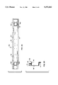
- FIG. 2A is a side view of one of the vertical rails shown in FIG. 1;
- FIG. 2B is an end view of the rail in FIG. 2A;
- FIG. 3 is an enlarged cross-section taken along line 3--3 of FIG. 1;
- FIG. 4 is a perspective, partially exploded view of the bottom frame of FIG. 1;
- FIG. 5 is an enlarged cross-section taken along line 55 of FIG. 1;
- FIG. 6 is an enlarged cross-section of another embodiment of the bottom frame of FIG. 1.
- FIG. 1 shows a partially disassembled frame assembly 2 which includes a top frame 4, a bottom frame 6, and four vertical rails 8a, 8b, 8c and 8d.
- FIG. 1 shows a partially disassembled frame assembly 2 which includes a top frame 4, a bottom frame 6, and four vertical rails 8a, 8b, 8c and 8d.
- FIG. 1 shows a partially disassembled frame assembly 2 which includes a top frame 4, a bottom frame 6, and four vertical rails 8a, 8b, 8c and 8d.
- the top frame 4 includes a panel 10 having a tubular perimeter 12. Apertures 11a, 11b, 11c and 11d disposed in the top surface of perimeter 12 are available for securing a top cover or panel (not shown) to the frame 4. Three downwardly-extending vertical supports (a fourth one of which is hidden from view) 16a, 16b and 16c are rigidly attached to the bottom of the perimeter 12 and are shaped to engage with the rails 8. Each vertical support 16 includes a plurality of apertures for receiving conventional fasteners such as rivets.
- the bottom frame 6 includes a tubular perimeter 18, two tubular members 20a and 20b, two surfaces 22a and 22b, a central open area 24 and three upwardly-extending vertical supports (a fourth being hidden from view) 26b, 26c and 26d which are similar to the vertical supports 16.
- Apertures 21a, 21b, 21c and 21d disposed around the outside of perimeter 18 are available for mounting a cover or skirt (not shown) to cover the gap between the bottom of frame 6 and the floor.
- the panel 27 may be solid or, alternatively, perforated to provide ventilation through the bottom of the assembly 2.
- the panel 27 may also be removed so that the area 24 may be used to mount a fan, for example.
- Conventional adjustable levelers 32a, 32b, 32c are disposed, respectively, near the corners of the bottom frame 6.
- rails 8a and 8c are identical (as are rails 8b and 8d) and the mirror image of rails 8b and 8d.
- Each rail 8 has a cross-section which is shaped to engage with one support 16 and one support 26.
- Each rail 8 includes two apertures, such as apertures 34a and 34b, which may serve, for example, as passageways for communication or power cables or the like.
- Each end of rails 8 includes a plurality of apertures, such as those denoted by reference numerals 9a and 9b, which correspond with similar apertures in the vertical supports 16 and 26, thus permitting the rails to be rigidly fastened to those supports by conventional fasteners such as rivets.
- each rail 8 includes two series of mounting apertures, like those denoted by reference numerals 11a and 11b, which are used for securing rack-mountable components to the rails 8.
- each "side" of assembly 2 i.e., the vertical area between an adjacent pair rails 8 and the top and bottom frames
- each "side" of assembly 2 is open and unobstructed by any brace or structural element.
- One of the advantages of such open areas is that access may be gained to the interior of the assembly 2 from any side, after removal of a covering panel, which makes installation, removal and servicing of attached rack-mountable components much easier.
- Another advantage is that the open areas provide ready-made passageways for interconnecting cables or wires in applications where multiple enclosures or cabinets built with frames like assembly 2 are interconnected.
- a typical frame assembly 2 is capable of supporting static loads of up to 2,000 pounds or more, depending upon choice of materials. As described in detail below, most of the components of assembly 2 are preferably made from flat metal stock using conventional techniques.
- FIGS. 2A and 2B one of the vertical rails 8d is shown in enlarged detail.
- One edge of a flat center portion 36 is integrally connected with a U-shaped flange 38, which extends the full length of the rail 8a.
- the flange 38 is in turn integrally connected with a first component mounting flange 40 in which the mounting apertures 11a (FIG. 1) are disposed.
- the opposite edge of the center portion 36 is integrally connected with a second, L-shaped component mounting flange 42 in which mounting apertures 11b are disposed.
- An end cap 44 is preferably welded, in a slightly recessed position, to each end of the rail 8d so as to cover the cross-sectional area of flange 38.
- the end cap 44 is preferably dimensioned to provide sufficient clearance between itself and the flange 42 to allow engagement of a support 16 or 26.
- the end caps 44 provide a mounting surface for optional adhesive-backed electromagnetic shields such as those denoted by reference numerals 96a and 96b (FIG. 1).
- the apertures 34c and 34d are preferably fitted with protective linings or grommets 46a and 46b, respectively, to protect cables and wires from rough edges of the apertures 34.
- Each grommet 46 may consist, for example, of a conventional rubber ring whose outer edge is grooved for engaging the edge of the aperture 34.
- the spacing between individual mounting apertures 11, as well as the lateral spacing between and orientation of the mounting flanges 40 and 42, are preferably chosen in accordance with recognized standards for rack-mountable equipment. Such standards are maintained by the Radio, Electronics and Television Manufacturers Association (RETMA) and other entities.
- RETMA Radio, Electronics and Television Manufacturers Association
- the rails 8 provide a high degree of stiffness once fastened to the vertical supports 16 and 26 (FIG. 1). More specifically, the cross-sections of rails 8 are shaped and dimensioned to yield an increased moment of inertia (as compared to conventional vertical supports), resulting in a corresponding increase in stiffness, while also maintaining compliance with spacing standards for rack-mountable equipment.
- the moment of inertia equals the product of an area (or mass) times the square of the distance to a reference line, if the distance to the reference line remains constant (e.g., to maintain standard spacing), then the area must increase to realize an increase in the moment of inertia.
- the "area" of the rail 8d is the product of the distance between the outer edge of flange 38 and that of flange 42 times the distance between the outer edge of flange 40 and that of center portion 36.
- flanges 38, 40 and 42 advantageously increases the distance between the outer edge of flange 38 and that of flange 42, thus increasing the moment of inertia and stiffness of the rail 8, while maintaining the desired standard spacing.
- the distance between the outer edge of flange 42 and that of flange 38 is preferably approximately 7" (175 mm) and the distance between the outer edge of flange 40 and flat portion 36 is approximately 2.25" (57 mm).
- the top frame 4 is preferably formed by two metal members.
- the panel 10 is actually a sheet whose edges 48 are rolled or formed to have a C-shaped cross-section, which edges are preferably flush and welded at the four corners (FIG. 1).
- a brace 50 includes a vertical portion 50a and two integral horizontal portions 50b and 50c which extend in opposite directions from opposite edges of the vertical portion. Portion 50c is attached to panel 10 while portion 50b is attached to the top surface of the edge 48, thereby forming the tubular perimeter 12.
- the brace 50 is preferably welded around its perimeter to both the panel 10 and the edges 48.
- the vertical support 16d is preferably welded to the bottom of perimeter 12 and is fastened by a plurality of rivets 52 to the vertical rail 8d. It should be noted that the top edges of rails 8 are preferably flush with the bottom of tubular perimeter 12, the advantages of which are described below.
- the tubular perimeter 12 formed by the combination of edge 48 and brace 50 substantially increases the stiffness of the top frame 4. Consequently, when the supports 16 are rigidly attached to their respective rails 8, the entire top portion of the assembly 2 resists substantial twisting forces.
- Top frame 4, and more specifically panel 10, advantageously provides a substantial central area which is unobstructed by structural members or braces. If left as a solid sheet, the panel 10 functions as an effective shield against electromagnetic emissions from within the interior of the assembly 2.
- the panel 10 is also readily usable for ventilation or other purposes to meet the requirements of a particular application.
- a portion of panel 10 may be perforated to allow air flow between the ambient atmosphere and the interior of the assembly 2. If such perforations are used, it may be necessary or desirable to cover the perforated area with a screen-type shield 54, secured by a fastener/bracket combination 56, to prevent excess electromagnetic emissions.
- FIG. 4 is a perspective view of the bottom frame 6 of FIG. 1, which frame is inverted to show certain features in greater detail. Certain components are omitted for greater clarity.
- the stabilizer guide 30 is a channel having a C-shaped cross-section which is dimensioned to slidingly engage an optional stabilizer arm 58 whose sides are slotted along their lengths.
- One end of arm 58 is fitted with a conventional level adjuster 60 while the other end of the arm is secured by a tether 62 to a point on the guide 30 using a conventional fasteners (not shown).
- the stabilizer arm 58 may be laterally extended (and level adjuster 60 set) to function as an "outrigger" for enhanced stability. Such enhanced stability may be desirable, for example, when service is being performed upon components mounted within the assembly 2.
- the tether 62 is preferably a predetermined length which prevents a user from inadvertently extending the arm 58 too far.
- Each caster assembly 64 consists of a caster 66 (either swivel or fixed type), a shock-absorbing mounting plate 68, a mounting bracket 70, a pin 72 and a variety of conventional fasteners (not shown) corresponding to the various apertures shown on these components.
- An anchor 74 disposed in the interior corner between perimeter 18 and tubular member 20b, is used in conjunction with a conventional fastener to secure the pin 72.
- Each exterior corner of the bottom frame 6 includes a plurality of apertures 76 which are used in conjunction with conventional pressed-in fasteners to secure structural brackets (not shown) for supporting doors or fastening two frame assemblies together.
- each half of the bottom frame 6 is preferably formed from two "nested" metal members 78 and 82.
- Member 78 has an inverted U-shaped cross-section and two inwardly-extending flanges 80a and 80b.
- Member 82 also has an inverted U-shaped cross-section, somewhat smaller than that of member 78, and two outwardly-extending flanges 84a and 84b which overlap flanges 80a and 80b, respectively. Member 82 thus nests within member 78, thereby forming the tubular perimeter 18 and member 20a.
- Member 78 is preferably welded to member 80.
- each vertical rail 8 (when attached to one of supports 26) is centered between a portion of the perimeter 18 and the adjacent member 20a or 20b.
- a primary advantage of this arrangement is that the loads applied by the rails 8 are substantially evenly distributed between the perimeter 18 and the members 20, thus reducing the likelihood of overloading one of the load-bearing members.
- the nested members 78 and 82 advantageously provide both the necessary vertical clearance and a suitably flat surface for mounting the caster assembly 64a. In the absence of such vertical clearance, the caster assembly 64a would increase the height of the frame assembly, which may prove unacceptable where uniform frame height is desired. Further, since the tubular perimeter 18 and the member 20a are load-bearing elements, stability and balance are enhanced by locating each caster assembly 64 between such elements and beneath the corresponding vertical rail 8.
- the bottom end of rail 8d is flush with surface 22a, just as the top end of rail 8d is flush with the bottom surface of perimeter 12 (FIG. 3).
- the absence of any gaps between the rails 8 and such surface means that the rails 8 are not free to rotate in a vertical plane separate from the top and bottom frames. That is, any force applied to a rail 8 which urges rotation in the vertical plane will be opposed by the tubular perimeter (or members) of the top and bottom frames, on which the rails 8 bear directly. This arrangement increases the stability of assembly 2.
- the panel 27 (FIG. 1) is fastened to the mounting bracket 28.
- An electromagnetic shield 86 is disposed between the sides of the panel 27 and member 20.
- FIG. 6 is an enlarged cross-section of an alternative embodiment of the bottom frame 6.
- a caster 66 unaccompanied by a shock-absorbing mount, is used to support the bottom frame 6. Since the caster 66 requires less vertical clearance than the shock-absorbing assembly 64a of FIG. 5, the bottom frame 6 may be formed in a different manner.
- a metal member 88 is formed with two inwardly-extending flanges 90a and 90b as well as a recessed area denoted "cable raceway" in its top surface.
- a second member 92 has two outwardly-extending flanges 94a and 94b and is shaped to nest with member 88.
- the members 88 and 92 When fastened together, preferably by welding, the members 88 and 92 form the tubular perimeter 18 and tubular member 20a, which function as load-bearing elements as described above in connection with FIG. 5.
- the recessed area on top of member 88 is advantageously available for use as a raceway for power or communication cables.
- the cable raceway may work, in conjunction with apertures 34 (FIG. 1), to route various cables within the interior of the assembly 2.
Abstract
Description
Claims (33)
Priority Applications (1)
| Application Number | Priority Date | Filing Date | Title |
|---|---|---|---|
| US07/723,396 US5372262A (en) | 1991-06-28 | 1991-06-28 | Frame assembly for rack-mountable equipment |
Applications Claiming Priority (1)
| Application Number | Priority Date | Filing Date | Title |
|---|---|---|---|
| US07/723,396 US5372262A (en) | 1991-06-28 | 1991-06-28 | Frame assembly for rack-mountable equipment |
Publications (1)
| Publication Number | Publication Date |
|---|---|
| US5372262A true US5372262A (en) | 1994-12-13 |
Family
ID=24906077
Family Applications (1)
| Application Number | Title | Priority Date | Filing Date |
|---|---|---|---|
| US07/723,396 Expired - Lifetime US5372262A (en) | 1991-06-28 | 1991-06-28 | Frame assembly for rack-mountable equipment |
Country Status (1)
| Country | Link |
|---|---|
| US (1) | US5372262A (en) |
Cited By (90)
| Publication number | Priority date | Publication date | Assignee | Title |
|---|---|---|---|---|
| US5517826A (en) * | 1995-03-14 | 1996-05-21 | Hussmann Corporation | Refrigerated merchandiser with modular external frame structure |
| US5584406A (en) * | 1993-09-28 | 1996-12-17 | Rittal-Werk Rudolf Loh Gmbh & Co. Kg | Rack frame |
| FR2738103A1 (en) * | 1995-08-24 | 1997-02-28 | Legrand Sa | CABIN FRAME, IN PARTICULAR FOR ELECTRICAL EQUIPMENT |
| US5645174A (en) * | 1994-11-18 | 1997-07-08 | Schroff Gmbh | Rack for an equipment cabinet |
| WO1997037570A1 (en) * | 1996-04-10 | 1997-10-16 | Bell Communications Research, Inc. | Earthquake resistant enclosure for electronic equipment |
| US5683001A (en) * | 1993-12-03 | 1997-11-04 | Nec Corporation | Rack for mounting electronic apparatuses |
| US5713584A (en) * | 1995-01-05 | 1998-02-03 | Crane; Brian J. | Multi-variant cart construction for transporting lighting equipment |
| US5732831A (en) * | 1993-08-09 | 1998-03-31 | Nokia Telecommunications Oy | Electrical appliance framework having a threaded bar for fixing of components to the framework |
| US5788087A (en) * | 1996-03-18 | 1998-08-04 | Ortronics, Inc. | Hinged wire management panel assembly |
| US5794795A (en) * | 1996-06-17 | 1998-08-18 | Stemmons; William L. | Framework system for electrical/electronic controls |
| US5806945A (en) * | 1995-09-22 | 1998-09-15 | Amco Engineering Co. | Modular enclosure and method |
| US5918750A (en) * | 1997-10-24 | 1999-07-06 | The Sports Authority Michigan, Inc. | Fixture for displaying merchandise |
| US5932843A (en) * | 1995-02-27 | 1999-08-03 | Rittal-Werk Rudolf Loh Gmbh & Co., Kg | Switchgear cabinet with a frame and door elements |
| EP0962168A1 (en) * | 1998-06-04 | 1999-12-08 | Siam Furniture Holdings Ltd. c/o Commonwealth Trust Ltd. | Storage cabinet and method of assembling same |
| US6006925A (en) * | 1997-06-03 | 1999-12-28 | Hendry Mechanical Works | Equipment rack system |
| US6202867B1 (en) | 1999-01-04 | 2001-03-20 | Terry Store - Age S.P.A. | Modular structure with modular component parts for making shelves and closets |
| US6202860B1 (en) * | 1999-10-07 | 2001-03-20 | W. H. Stewart Co. | Electronic equipment enclosure |
| US6213577B1 (en) * | 1998-07-23 | 2001-04-10 | The Foxboro Company | Equipment storage apparatus |
| US6223908B1 (en) * | 1999-09-15 | 2001-05-01 | Homaco, Inc. | Adjustable communications equipment dual relay rack |
| US6237783B1 (en) * | 1998-03-27 | 2001-05-29 | Advantest Corporation | Apparatus for storing customer trays |
| US6290072B1 (en) * | 1997-09-18 | 2001-09-18 | Fujitsu Limited | Library apparatus |
| US6293637B1 (en) | 2000-05-12 | 2001-09-25 | Amco Engineering Co. | Earthquake-resistant electronic equipment frame |
| US6401940B1 (en) * | 1998-03-18 | 2002-06-11 | Rittal-Werk Rudolf Loh Gmbh & Co. Kg | Frame for a switch cabinet |
| US6425648B1 (en) * | 2000-04-12 | 2002-07-30 | International Business Machines Corporation | Modular and flexible server frame enclosure |
| WO2002061559A2 (en) * | 2001-01-30 | 2002-08-08 | Ortronics, Inc | Equipment mounting strap |
| US6457595B1 (en) | 1998-11-17 | 2002-10-01 | L&P Property Management Company | Configurable shelving/storage system |
| US6481582B1 (en) | 2001-06-04 | 2002-11-19 | Cooper Technologies Company | Rack |
| US20020171340A1 (en) * | 2001-05-15 | 2002-11-21 | Prima Corporation | Support member having a recess for routing cables and method of routing cables in an electronic equipment cabinet |
| US6502702B1 (en) * | 2001-11-21 | 2003-01-07 | 3Pardata, Inc. | Rack cabinet and method for making same |
| US6517174B2 (en) | 1998-06-23 | 2003-02-11 | Hendry Telephone Products | Equipment mounting racks and cabinets |
| US6519775B1 (en) * | 1998-05-08 | 2003-02-18 | Nicolas Garcia | Thigh protective device for construction workers and method of using same |
| US6520355B1 (en) | 1999-03-26 | 2003-02-18 | L&P Property Management Company | Adjustable shelving/display system |
| US6561602B1 (en) | 1998-06-23 | 2003-05-13 | Hendry Mechanical Works | Equipment mounting racks and cabinets |
| US6605777B1 (en) * | 2002-07-29 | 2003-08-12 | Amco Engineering Co. | Earthquake-resistant electronic equipment frame |
| US6659295B1 (en) | 1999-03-26 | 2003-12-09 | L&P Property Management Company | Adjustable shelving/display system |
| US20040004418A1 (en) * | 2002-05-23 | 2004-01-08 | Brendan Wyatt | Indoor-outdoor equipment enclosure and method for assembling the same |
| US20040016713A1 (en) * | 2002-04-01 | 2004-01-29 | Brendan Wyatt | Corner post and manufacturing process for making same |
| US20040069725A1 (en) * | 2002-07-10 | 2004-04-15 | Adducci Samuel J. | Seismically resistant network equipment rack |
| US20040183409A1 (en) * | 2001-01-23 | 2004-09-23 | Cooper Technologies Company | Electrical equipment enclosure |
| US20040190247A1 (en) * | 2002-11-25 | 2004-09-30 | International Business Machines Corporation | Method for combined air and liquid cooling of stacked electronics components |
| US20040245305A1 (en) * | 2003-06-06 | 2004-12-09 | Nicolas Garcia | Waist supported structure with attachment band |
| FR2866217A1 (en) * | 2004-02-13 | 2005-08-19 | Pierre Henry Sa | Storage furniture e.g. cabinet, for office, has reinforcing stretcher received between side rails in removable manner, door sliding and closing unit snapped in reversible manner on frame, and bottom plate removably mounted on frame |
| US20060043031A1 (en) * | 2004-08-26 | 2006-03-02 | Cooper Technologies Company | Electronic equipment rack |
| US20060066065A1 (en) * | 2004-09-29 | 2006-03-30 | Delaware Capital Formation, Inc. | Removable caster system |
| US20070095774A1 (en) * | 2005-10-28 | 2007-05-03 | International Business Machines Corporation | Integrated frame and central electronic complex structure |
| US20070178369A1 (en) * | 2006-02-02 | 2007-08-02 | William Conrardy | Tiered battery cabinet |
| US20070175836A1 (en) * | 2006-01-27 | 2007-08-02 | Gerhard Bumeder | Frame structure |
| US20070278915A1 (en) * | 2006-05-05 | 2007-12-06 | C&C Power, Inc. | Equipment cabinet |
| US20080169737A1 (en) * | 2007-01-16 | 2008-07-17 | Min-Dy Shen | Adjustable Pull-Out Frame Structure |
| US20090091880A1 (en) * | 2007-10-09 | 2009-04-09 | International Business Machines Corporation | Assembly And Method For Ruggedizing Computer Racks And/Or Electronic Cage Assemblies |
| US20090250422A1 (en) * | 2008-04-04 | 2009-10-08 | Target Brands, Inc. | Fixture accessories |
| US20090283488A1 (en) * | 2008-05-19 | 2009-11-19 | Chatsworth Products, Inc. | Seismically hardened two-post electronic equipment rack |
| US20100059950A1 (en) * | 2008-08-26 | 2010-03-11 | Coghill Jr Thomas E | Modular beach cart system |
| US20110181160A1 (en) * | 2010-01-25 | 2011-07-28 | Hong Fu Jin Precision Industry (Shenzhen) Co., Ltd. | Switching cabinet and assembly method of the same |
| US20120193308A1 (en) * | 2007-04-26 | 2012-08-02 | Blackhawk Labs Llc | Apparatus and method for housing electronic equipment and increasing floor space utilization in a secure environment |
| JP2012204516A (en) * | 2011-03-24 | 2012-10-22 | Kawamura Electric Inc | Cabinet connection structure |
| US20130342091A1 (en) * | 2012-06-25 | 2013-12-26 | Panduit Corp. | Server Cabinet |
| US8787023B2 (en) | 2010-09-10 | 2014-07-22 | Chatsworth Products, Inc. | Rail mounting clamp for electronic equipment enclosure |
| US20140263129A1 (en) * | 2013-03-12 | 2014-09-18 | Ching-Chao Tseng | Rack assembly |
| US8901438B2 (en) | 2010-09-10 | 2014-12-02 | Chatsworth Products, Inc. | Electronic equipment cabinet structure |
| US8905370B2 (en) * | 2012-11-29 | 2014-12-09 | Shenzhen China Star Optoelectronics Technology Co., Ltd. | Supporting device for display apparatus |
| US20150143957A1 (en) * | 2013-11-25 | 2015-05-28 | Gooten Innolife Corporation | Watch winder case |
| US9055677B2 (en) | 2010-09-10 | 2015-06-09 | Chatsworth Products, Inc. | Cable pass-through panel for electronic equipment enclosure |
| CN104735930A (en) * | 2013-12-23 | 2015-06-24 | 鸿富锦精密电子(天津)有限公司 | Server cabinet |
| US9119487B2 (en) | 2013-09-13 | 2015-09-01 | Target Brands, Inc. | Display system |
| US9126613B2 (en) * | 2014-01-09 | 2015-09-08 | Carter Hoffmann, Inc. | Movable cart |
| US9144175B2 (en) | 2012-06-25 | 2015-09-22 | Panduit Corp. | Electronics cabinet |
| US9301603B1 (en) * | 2014-10-09 | 2016-04-05 | Quality Craft Industries, Inc. | Collapsible storage cabinet |
| US20160360638A1 (en) * | 2015-06-04 | 2016-12-08 | International Business Machines Corporation | Safety apparatus for electrical equipment rack |
| US20160381824A1 (en) * | 2015-06-25 | 2016-12-29 | Facebook, Inc. | Open chassis and server module incorporating the same |
| US20170007039A1 (en) * | 2014-02-14 | 2017-01-12 | Aht Cooling Systems Gmbh | Refrigerated Display Case |
| US9943003B2 (en) | 2012-06-25 | 2018-04-10 | Panduit Corp. | Electronics cabinet |
| US10071303B2 (en) | 2015-08-26 | 2018-09-11 | Malibu Innovations, LLC | Mobilized cooler device with fork hanger assembly |
| US20180274713A1 (en) * | 2015-01-14 | 2018-09-27 | Atlas Copco Airpower, Naamloze Vennootschap | Housing for a compressor or expander installation, vacuum pump, generator or the like |
| US10271449B1 (en) * | 2006-02-28 | 2019-04-23 | Gorgius L Yousif | Mount rack frame |
| US10330299B1 (en) * | 2018-05-31 | 2019-06-25 | Mitek Corp., Inc. | Electronic rack crown |
| US10357104B2 (en) * | 2016-01-30 | 2019-07-23 | Eaton Intelligent Power Limited | Equipment rack having caster brackets |
| US20200170140A1 (en) * | 2018-11-28 | 2020-05-28 | Doron Moshe | Securing Mechanism for Casing for Transporting Communications Computers and Electronics Racks |
| US10807659B2 (en) | 2016-05-27 | 2020-10-20 | Joseph L. Pikulski | Motorized platforms |
| US11167908B2 (en) * | 2018-11-28 | 2021-11-09 | Doron Moshe | Securing mechanism for casing for transporting communications computers and electronics racks |
| US11408456B2 (en) * | 2019-08-02 | 2022-08-09 | Hoffman Enclosures Inc. | Integral installation aid |
| US11576277B2 (en) * | 2020-02-14 | 2023-02-07 | Quanta Computer Inc. | Rack for supporting servers of varying heights |
| US11622458B1 (en) | 2020-12-15 | 2023-04-04 | Chatsworth Products, Inc. | Brush port assembly and method for installing same |
| US11622469B2 (en) | 2020-05-04 | 2023-04-04 | Panduit Corp. | Data center cabinet and reusable transport casters for a data center cabinet |
| US11678458B1 (en) | 2020-12-15 | 2023-06-13 | Chatsworth Products, Inc. | Slidable mounting hardware for electronic equipment enclosure and method for installing same |
| US11717097B2 (en) * | 2020-05-22 | 2023-08-08 | American Business Forms, Inc. | Moveable base for retail gondola |
| US11785734B2 (en) | 2020-05-04 | 2023-10-10 | Panduit Corp. | Data center cabinet and top caps for a data center cabinet |
| US11818860B1 (en) | 2020-12-15 | 2023-11-14 | Chatsworth Products, Inc. | Frame structure for electronic equipment enclosure |
| US11920392B1 (en) | 2021-02-02 | 2024-03-05 | Chatsworth Products, Inc. | Electrical bonding door hinges |
| US11968798B2 (en) | 2021-06-30 | 2024-04-23 | Panduit Corp. | Transport caster assembly for a data center cabinet |
Citations (17)
| Publication number | Priority date | Publication date | Assignee | Title |
|---|---|---|---|---|
| US2926022A (en) * | 1957-07-31 | 1960-02-23 | David H Nau | Food cart |
| US3034844A (en) * | 1958-01-21 | 1962-05-15 | Amco Eng | Enclosure |
| CH379714A (en) * | 1959-12-12 | 1964-07-15 | Hobson Nancy | Arrangement with a support element, in particular a console or a shelf |
| US3265419A (en) * | 1963-12-30 | 1966-08-09 | Honeywell Inc | Cabinet structure |
| US3305623A (en) * | 1964-10-19 | 1967-02-21 | Metex Corp | Shielded window construction |
| US3541395A (en) * | 1968-11-15 | 1970-11-17 | Lockheed Aircraft Corp | Aviation rack with cooling ducts |
| US3966285A (en) * | 1974-07-17 | 1976-06-29 | Porch Don E | Collapsible shipping container |
| US4131934A (en) * | 1976-06-25 | 1978-12-26 | Siemens Aktiengesellschaft | Receptacle fixture for equipment units in electrical communication technology |
| FR2448239A1 (en) * | 1979-02-02 | 1980-08-29 | Alsthom Cgee | Equipment rack has four vertical corner members - with vertical lips with holes for attaching flush side panels and cross-members |
| SU928483A1 (en) * | 1980-08-20 | 1982-05-15 | Предприятие П/Я В-2190 | Cabinet for electric apparatus |
| US4497411A (en) * | 1982-04-19 | 1985-02-05 | Northern Telecom Limited | Distributing frame for telecommunications systems |
| US4643319A (en) * | 1983-12-09 | 1987-02-17 | Rittal-Werk Rudolf Loh Gmbh & Co. Kg | Framework for a switchboard cabinet |
| US4777565A (en) * | 1986-03-15 | 1988-10-11 | Unisys Corporation | Shielded equipment enclosure |
| US4988008A (en) * | 1989-06-19 | 1991-01-29 | Siemens Aktiengesellschaft | Supporting framework for a control cabinet |
| US4997240A (en) * | 1989-03-28 | 1991-03-05 | Siemens Aktiengesellschaft | Modular housing system for electronic equipment |
| US5016765A (en) * | 1989-08-23 | 1991-05-21 | Leonardo Stephen V | Modular frame assembly and method for making same |
| US5049701A (en) * | 1989-09-28 | 1991-09-17 | Stratus Computer, Inc. | EMI cabinet with improved interference suppression |
-
1991
- 1991-06-28 US US07/723,396 patent/US5372262A/en not_active Expired - Lifetime
Patent Citations (17)
| Publication number | Priority date | Publication date | Assignee | Title |
|---|---|---|---|---|
| US2926022A (en) * | 1957-07-31 | 1960-02-23 | David H Nau | Food cart |
| US3034844A (en) * | 1958-01-21 | 1962-05-15 | Amco Eng | Enclosure |
| CH379714A (en) * | 1959-12-12 | 1964-07-15 | Hobson Nancy | Arrangement with a support element, in particular a console or a shelf |
| US3265419A (en) * | 1963-12-30 | 1966-08-09 | Honeywell Inc | Cabinet structure |
| US3305623A (en) * | 1964-10-19 | 1967-02-21 | Metex Corp | Shielded window construction |
| US3541395A (en) * | 1968-11-15 | 1970-11-17 | Lockheed Aircraft Corp | Aviation rack with cooling ducts |
| US3966285A (en) * | 1974-07-17 | 1976-06-29 | Porch Don E | Collapsible shipping container |
| US4131934A (en) * | 1976-06-25 | 1978-12-26 | Siemens Aktiengesellschaft | Receptacle fixture for equipment units in electrical communication technology |
| FR2448239A1 (en) * | 1979-02-02 | 1980-08-29 | Alsthom Cgee | Equipment rack has four vertical corner members - with vertical lips with holes for attaching flush side panels and cross-members |
| SU928483A1 (en) * | 1980-08-20 | 1982-05-15 | Предприятие П/Я В-2190 | Cabinet for electric apparatus |
| US4497411A (en) * | 1982-04-19 | 1985-02-05 | Northern Telecom Limited | Distributing frame for telecommunications systems |
| US4643319A (en) * | 1983-12-09 | 1987-02-17 | Rittal-Werk Rudolf Loh Gmbh & Co. Kg | Framework for a switchboard cabinet |
| US4777565A (en) * | 1986-03-15 | 1988-10-11 | Unisys Corporation | Shielded equipment enclosure |
| US4997240A (en) * | 1989-03-28 | 1991-03-05 | Siemens Aktiengesellschaft | Modular housing system for electronic equipment |
| US4988008A (en) * | 1989-06-19 | 1991-01-29 | Siemens Aktiengesellschaft | Supporting framework for a control cabinet |
| US5016765A (en) * | 1989-08-23 | 1991-05-21 | Leonardo Stephen V | Modular frame assembly and method for making same |
| US5049701A (en) * | 1989-09-28 | 1991-09-17 | Stratus Computer, Inc. | EMI cabinet with improved interference suppression |
Non-Patent Citations (2)
| Title |
|---|
| Digital Equipment Corporation H9544 JA Expansion Cabinet Kit, pp. 1 2. * |
| Digital Equipment Corporation H9544-JA Expansion Cabinet Kit, pp. 1-2. |
Cited By (160)
| Publication number | Priority date | Publication date | Assignee | Title |
|---|---|---|---|---|
| US5732831A (en) * | 1993-08-09 | 1998-03-31 | Nokia Telecommunications Oy | Electrical appliance framework having a threaded bar for fixing of components to the framework |
| US5584406A (en) * | 1993-09-28 | 1996-12-17 | Rittal-Werk Rudolf Loh Gmbh & Co. Kg | Rack frame |
| US5683001A (en) * | 1993-12-03 | 1997-11-04 | Nec Corporation | Rack for mounting electronic apparatuses |
| US5645174A (en) * | 1994-11-18 | 1997-07-08 | Schroff Gmbh | Rack for an equipment cabinet |
| US5713584A (en) * | 1995-01-05 | 1998-02-03 | Crane; Brian J. | Multi-variant cart construction for transporting lighting equipment |
| US5932843A (en) * | 1995-02-27 | 1999-08-03 | Rittal-Werk Rudolf Loh Gmbh & Co., Kg | Switchgear cabinet with a frame and door elements |
| WO1996028074A1 (en) * | 1995-03-14 | 1996-09-19 | Hussmann Corporation | Refrigerated merchandiser with modular external frame structure |
| US5517826A (en) * | 1995-03-14 | 1996-05-21 | Hussmann Corporation | Refrigerated merchandiser with modular external frame structure |
| FR2738103A1 (en) * | 1995-08-24 | 1997-02-28 | Legrand Sa | CABIN FRAME, IN PARTICULAR FOR ELECTRICAL EQUIPMENT |
| EP0762819A1 (en) * | 1995-08-24 | 1997-03-12 | Legrand | Cabinet frame, particularly for electrical apparatus |
| CN1079631C (en) * | 1995-08-24 | 2002-02-20 | 勒格朗公司 | Case-cabinet frame special for electric apparatus |
| US5806945A (en) * | 1995-09-22 | 1998-09-15 | Amco Engineering Co. | Modular enclosure and method |
| US5788087A (en) * | 1996-03-18 | 1998-08-04 | Ortronics, Inc. | Hinged wire management panel assembly |
| US5979672A (en) * | 1996-04-10 | 1999-11-09 | Telcordia Technologies, Inc. | Earthquake resistant enclosure for electronic equipment |
| WO1997037570A1 (en) * | 1996-04-10 | 1997-10-16 | Bell Communications Research, Inc. | Earthquake resistant enclosure for electronic equipment |
| US5794795A (en) * | 1996-06-17 | 1998-08-18 | Stemmons; William L. | Framework system for electrical/electronic controls |
| US6006925A (en) * | 1997-06-03 | 1999-12-28 | Hendry Mechanical Works | Equipment rack system |
| US6290072B1 (en) * | 1997-09-18 | 2001-09-18 | Fujitsu Limited | Library apparatus |
| US5918750A (en) * | 1997-10-24 | 1999-07-06 | The Sports Authority Michigan, Inc. | Fixture for displaying merchandise |
| US6401940B1 (en) * | 1998-03-18 | 2002-06-11 | Rittal-Werk Rudolf Loh Gmbh & Co. Kg | Frame for a switch cabinet |
| US6237783B1 (en) * | 1998-03-27 | 2001-05-29 | Advantest Corporation | Apparatus for storing customer trays |
| US6519775B1 (en) * | 1998-05-08 | 2003-02-18 | Nicolas Garcia | Thigh protective device for construction workers and method of using same |
| EP0962168A1 (en) * | 1998-06-04 | 1999-12-08 | Siam Furniture Holdings Ltd. c/o Commonwealth Trust Ltd. | Storage cabinet and method of assembling same |
| US6517174B2 (en) | 1998-06-23 | 2003-02-11 | Hendry Telephone Products | Equipment mounting racks and cabinets |
| US6561602B1 (en) | 1998-06-23 | 2003-05-13 | Hendry Mechanical Works | Equipment mounting racks and cabinets |
| US6527351B1 (en) | 1998-06-23 | 2003-03-04 | Hendry Mechanical Works | Equipment mounting racks and cabinets |
| US6213577B1 (en) * | 1998-07-23 | 2001-04-10 | The Foxboro Company | Equipment storage apparatus |
| US6457595B1 (en) | 1998-11-17 | 2002-10-01 | L&P Property Management Company | Configurable shelving/storage system |
| US6202867B1 (en) | 1999-01-04 | 2001-03-20 | Terry Store - Age S.P.A. | Modular structure with modular component parts for making shelves and closets |
| US6659295B1 (en) | 1999-03-26 | 2003-12-09 | L&P Property Management Company | Adjustable shelving/display system |
| US20040055514A1 (en) * | 1999-03-26 | 2004-03-25 | L&P Property Management Company | Adjustable shelving/display system |
| US6918499B2 (en) | 1999-03-26 | 2005-07-19 | L&P Property Management Company | Adjustable shelving/display system |
| US6520355B1 (en) | 1999-03-26 | 2003-02-18 | L&P Property Management Company | Adjustable shelving/display system |
| US6223908B1 (en) * | 1999-09-15 | 2001-05-01 | Homaco, Inc. | Adjustable communications equipment dual relay rack |
| US6202860B1 (en) * | 1999-10-07 | 2001-03-20 | W. H. Stewart Co. | Electronic equipment enclosure |
| US6425648B1 (en) * | 2000-04-12 | 2002-07-30 | International Business Machines Corporation | Modular and flexible server frame enclosure |
| US6293637B1 (en) | 2000-05-12 | 2001-09-25 | Amco Engineering Co. | Earthquake-resistant electronic equipment frame |
| US20040183409A1 (en) * | 2001-01-23 | 2004-09-23 | Cooper Technologies Company | Electrical equipment enclosure |
| WO2002061559A2 (en) * | 2001-01-30 | 2002-08-08 | Ortronics, Inc | Equipment mounting strap |
| WO2002061559A3 (en) * | 2001-01-30 | 2003-02-20 | Ortronics Inc | Equipment mounting strap |
| US6598270B2 (en) | 2001-01-30 | 2003-07-29 | Ortronics, Inc. | Equipment mounting strap |
| US20020172013A1 (en) * | 2001-05-15 | 2002-11-21 | Prima Corporation | Method of attaching supports to an electronic equipment cabinet |
| US20020171340A1 (en) * | 2001-05-15 | 2002-11-21 | Prima Corporation | Support member having a recess for routing cables and method of routing cables in an electronic equipment cabinet |
| US6481582B1 (en) | 2001-06-04 | 2002-11-19 | Cooper Technologies Company | Rack |
| US6502702B1 (en) * | 2001-11-21 | 2003-01-07 | 3Pardata, Inc. | Rack cabinet and method for making same |
| US20050284833A1 (en) * | 2002-04-01 | 2005-12-29 | Brendan Wyatt | Corner post and maufacturing process for making same |
| US20040016713A1 (en) * | 2002-04-01 | 2004-01-29 | Brendan Wyatt | Corner post and manufacturing process for making same |
| US6974036B2 (en) | 2002-04-01 | 2005-12-13 | Viasystems Group, Inc. | Corner post and manufacturing process for making same |
| US7086707B2 (en) | 2002-05-23 | 2006-08-08 | Viasystems Group, Inc. | Indoor-outdoor equipment enclosure and method for assembling the same |
| US7316461B2 (en) | 2002-05-23 | 2008-01-08 | Viasystems Group, Inc. | Indoor-outdoor equipment enclosure and method for assembling the same |
| US20040004418A1 (en) * | 2002-05-23 | 2004-01-08 | Brendan Wyatt | Indoor-outdoor equipment enclosure and method for assembling the same |
| US20060267464A1 (en) * | 2002-05-23 | 2006-11-30 | Brendan Wyatt | Indoor-outdoor equipment enclosure and method for assembling the same |
| US20040069725A1 (en) * | 2002-07-10 | 2004-04-15 | Adducci Samuel J. | Seismically resistant network equipment rack |
| US6605777B1 (en) * | 2002-07-29 | 2003-08-12 | Amco Engineering Co. | Earthquake-resistant electronic equipment frame |
| US20040190247A1 (en) * | 2002-11-25 | 2004-09-30 | International Business Machines Corporation | Method for combined air and liquid cooling of stacked electronics components |
| US6924981B2 (en) * | 2002-11-25 | 2005-08-02 | International Business Machines Corporation | Method for combined air and liquid cooling of stacked electronics components |
| US20040245305A1 (en) * | 2003-06-06 | 2004-12-09 | Nicolas Garcia | Waist supported structure with attachment band |
| FR2866217A1 (en) * | 2004-02-13 | 2005-08-19 | Pierre Henry Sa | Storage furniture e.g. cabinet, for office, has reinforcing stretcher received between side rails in removable manner, door sliding and closing unit snapped in reversible manner on frame, and bottom plate removably mounted on frame |
| US20060043031A1 (en) * | 2004-08-26 | 2006-03-02 | Cooper Technologies Company | Electronic equipment rack |
| US7374186B2 (en) * | 2004-09-29 | 2008-05-20 | Dover Systems, Inc. | Removable caster system |
| US20060066065A1 (en) * | 2004-09-29 | 2006-03-30 | Delaware Capital Formation, Inc. | Removable caster system |
| US20070095774A1 (en) * | 2005-10-28 | 2007-05-03 | International Business Machines Corporation | Integrated frame and central electronic complex structure |
| US8079481B2 (en) * | 2005-10-28 | 2011-12-20 | International Business Machines Corporation | Integrated frame and central electronic complex structure |
| US20070175836A1 (en) * | 2006-01-27 | 2007-08-02 | Gerhard Bumeder | Frame structure |
| US20070178369A1 (en) * | 2006-02-02 | 2007-08-02 | William Conrardy | Tiered battery cabinet |
| US10312484B2 (en) | 2006-02-02 | 2019-06-04 | C & C Power, Inc. | Tiered battery cabinet |
| US9312525B2 (en) | 2006-02-02 | 2016-04-12 | C & C Power Inc | Tiered battery cabinet |
| US9112205B2 (en) | 2006-02-02 | 2015-08-18 | C & C Power | Tiered battery cabinet |
| US8100271B2 (en) | 2006-02-02 | 2012-01-24 | C & C Power | Tiered battery cabinet |
| US10271449B1 (en) * | 2006-02-28 | 2019-04-23 | Gorgius L Yousif | Mount rack frame |
| US20070278915A1 (en) * | 2006-05-05 | 2007-12-06 | C&C Power, Inc. | Equipment cabinet |
| US9301408B2 (en) | 2006-05-05 | 2016-03-29 | C & C Power, Inc. | Equipment cabinet |
| US9755200B2 (en) | 2006-05-05 | 2017-09-05 | C & C Pwere, Inc. | Equipment cabinet |
| US8721010B2 (en) * | 2006-05-05 | 2014-05-13 | C&C Power, Inc | Equipment cabinet |
| US20080169737A1 (en) * | 2007-01-16 | 2008-07-17 | Min-Dy Shen | Adjustable Pull-Out Frame Structure |
| US10806048B2 (en) | 2007-04-26 | 2020-10-13 | Blackhawk Labs Llc | Apparatus and method for housing electronic equipment and increasing floor space utilization in a secure environment |
| US20120193308A1 (en) * | 2007-04-26 | 2012-08-02 | Blackhawk Labs Llc | Apparatus and method for housing electronic equipment and increasing floor space utilization in a secure environment |
| US10321598B2 (en) | 2007-04-26 | 2019-06-11 | Blackhawk Labs Llc | Apparatus and method for housing electronic equipment and increasing floor space utilization in a secure environment |
| US20090091880A1 (en) * | 2007-10-09 | 2009-04-09 | International Business Machines Corporation | Assembly And Method For Ruggedizing Computer Racks And/Or Electronic Cage Assemblies |
| US7848109B2 (en) * | 2007-10-09 | 2010-12-07 | International Business Machines Corporation | Assembly and method for ruggedizing computer racks and/or electronic cage assemblies |
| US8434630B2 (en) | 2008-04-04 | 2013-05-07 | Target Brands, Inc. | Merchandising system and method of assembly |
| US20090250422A1 (en) * | 2008-04-04 | 2009-10-08 | Target Brands, Inc. | Fixture accessories |
| US8191720B2 (en) | 2008-04-04 | 2012-06-05 | Target Brands, Inc. | Method of assembling fixture accessories |
| US20110209329A1 (en) * | 2008-04-04 | 2011-09-01 | Target Brands, Inc. | Fixture Accessories |
| US7946435B2 (en) * | 2008-04-04 | 2011-05-24 | Target Brands, Inc. | Fixture accessories |
| US8424691B2 (en) | 2008-05-19 | 2013-04-23 | Chatsworth Products, Inc. | Seismically hardened two-post electronic equipment rack |
| US20090283488A1 (en) * | 2008-05-19 | 2009-11-19 | Chatsworth Products, Inc. | Seismically hardened two-post electronic equipment rack |
| US8465031B2 (en) * | 2008-08-26 | 2013-06-18 | Ronald Ritter | Modular beach cart system |
| US20100059950A1 (en) * | 2008-08-26 | 2010-03-11 | Coghill Jr Thomas E | Modular beach cart system |
| US20110181160A1 (en) * | 2010-01-25 | 2011-07-28 | Hong Fu Jin Precision Industry (Shenzhen) Co., Ltd. | Switching cabinet and assembly method of the same |
| US9781852B2 (en) | 2010-09-10 | 2017-10-03 | Chatsworth Products, Inc. | Cable pass-through panel for electronic equipment enclosure |
| US9408326B2 (en) * | 2010-09-10 | 2016-08-02 | Chatsworth Products, Inc. | Electronic equipment cabinet structure |
| US9980400B2 (en) | 2010-09-10 | 2018-05-22 | Chatsworth Products, Inc. | Rail seal for electronic equipment enclosure |
| US11039543B2 (en) | 2010-09-10 | 2021-06-15 | Chatsworth Products, Inc. | Vertical mounting rail with cable management features |
| US8787023B2 (en) | 2010-09-10 | 2014-07-22 | Chatsworth Products, Inc. | Rail mounting clamp for electronic equipment enclosure |
| US10237994B2 (en) | 2010-09-10 | 2019-03-19 | Chatsworth Products, Inc. | Vertical mounting rail with cable management features |
| US10588227B2 (en) | 2010-09-10 | 2020-03-10 | Chatsworth Products, Inc. | Vertical mounting rail with cable management features |
| US9814159B2 (en) | 2010-09-10 | 2017-11-07 | Chatsworth Products, Inc. | Rail seal for electronic equipment enclosure |
| US20150069888A1 (en) * | 2010-09-10 | 2015-03-12 | Chatsworth Products, Inc. | Electronic equipment cabinet structure |
| US10178784B2 (en) | 2010-09-10 | 2019-01-08 | Chatsworth Products, Inc. | Rail seal for electronic equipment enclosure |
| US9055677B2 (en) | 2010-09-10 | 2015-06-09 | Chatsworth Products, Inc. | Cable pass-through panel for electronic equipment enclosure |
| US8901438B2 (en) | 2010-09-10 | 2014-12-02 | Chatsworth Products, Inc. | Electronic equipment cabinet structure |
| US9642270B2 (en) | 2010-09-10 | 2017-05-02 | Chatsworth Products, Inc. | Rail seal for electronic equipment enclosure |
| US11792948B2 (en) | 2010-09-10 | 2023-10-17 | Chatsworth Products, Inc. | Cable pass-through panel for electronic equipment enclosure |
| US11464123B2 (en) | 2010-09-10 | 2022-10-04 | Chatsworth Products, Inc. | Method of adapting an electronic equipment enclosure for cable management |
| US10653025B2 (en) | 2010-09-10 | 2020-05-12 | Chatsworth Products, Inc. | Cable pass-through panel for electronic equipment enclosure |
| JP2012204516A (en) * | 2011-03-24 | 2012-10-22 | Kawamura Electric Inc | Cabinet connection structure |
| US9510471B2 (en) | 2012-06-25 | 2016-11-29 | Panduit Corp. | Electronics cabinet |
| US9648778B2 (en) | 2012-06-25 | 2017-05-09 | Panduit Corp. | Electronics cabinet |
| US8901418B2 (en) * | 2012-06-25 | 2014-12-02 | Panduit Corp. | Server cabinet |
| US9144175B2 (en) | 2012-06-25 | 2015-09-22 | Panduit Corp. | Electronics cabinet |
| US20130342091A1 (en) * | 2012-06-25 | 2013-12-26 | Panduit Corp. | Server Cabinet |
| US9943003B2 (en) | 2012-06-25 | 2018-04-10 | Panduit Corp. | Electronics cabinet |
| US8905370B2 (en) * | 2012-11-29 | 2014-12-09 | Shenzhen China Star Optoelectronics Technology Co., Ltd. | Supporting device for display apparatus |
| US20140263129A1 (en) * | 2013-03-12 | 2014-09-18 | Ching-Chao Tseng | Rack assembly |
| US9119487B2 (en) | 2013-09-13 | 2015-09-01 | Target Brands, Inc. | Display system |
| US20150143957A1 (en) * | 2013-11-25 | 2015-05-28 | Gooten Innolife Corporation | Watch winder case |
| US20150173508A1 (en) * | 2013-12-23 | 2015-06-25 | Hon Hai Precision Industry Co., Ltd. | Server cabinet |
| CN104735930A (en) * | 2013-12-23 | 2015-06-24 | 鸿富锦精密电子(天津)有限公司 | Server cabinet |
| US9126613B2 (en) * | 2014-01-09 | 2015-09-08 | Carter Hoffmann, Inc. | Movable cart |
| US10420426B2 (en) * | 2014-02-14 | 2019-09-24 | Aht Cooling Systems Gmbh | Refrigerated display case |
| US20170007039A1 (en) * | 2014-02-14 | 2017-01-12 | Aht Cooling Systems Gmbh | Refrigerated Display Case |
| US9301603B1 (en) * | 2014-10-09 | 2016-04-05 | Quality Craft Industries, Inc. | Collapsible storage cabinet |
| US20180274713A1 (en) * | 2015-01-14 | 2018-09-27 | Atlas Copco Airpower, Naamloze Vennootschap | Housing for a compressor or expander installation, vacuum pump, generator or the like |
| US10920921B2 (en) * | 2015-01-14 | 2021-02-16 | Atlas Copco Airpower, Naamloze Vennootschap | Housing for a compressor or expander installation, vacuum pump, generator or the like |
| US10178911B2 (en) * | 2015-06-04 | 2019-01-15 | International Business Machines Corporation | Safety apparatus for electrical equipment rack |
| US10390619B2 (en) | 2015-06-04 | 2019-08-27 | International Business Machines Corporation | Safety apparatus for electrical equipment rack |
| US20160360638A1 (en) * | 2015-06-04 | 2016-12-08 | International Business Machines Corporation | Safety apparatus for electrical equipment rack |
| US10582772B2 (en) | 2015-06-04 | 2020-03-10 | International Business Machines Corporation | Safety apparatus for electrical equipment rack |
| US10165702B2 (en) * | 2015-06-25 | 2018-12-25 | Facebook, Inc. | Open chassis and server module incorporating the same |
| US20160381824A1 (en) * | 2015-06-25 | 2016-12-29 | Facebook, Inc. | Open chassis and server module incorporating the same |
| US9918397B2 (en) * | 2015-06-25 | 2018-03-13 | Facebook, Inc. | Open chassis and server module incorporating the same |
| US10071303B2 (en) | 2015-08-26 | 2018-09-11 | Malibu Innovations, LLC | Mobilized cooler device with fork hanger assembly |
| US10814211B2 (en) | 2015-08-26 | 2020-10-27 | Joseph Pikulski | Mobilized platforms |
| US10561038B2 (en) | 2016-01-30 | 2020-02-11 | Eaton Intelligent Power Limited | Equipment rack having mounting brackets |
| US10492605B2 (en) | 2016-01-30 | 2019-12-03 | Eaton Intelligent Power Limited | Mounting bracket for equipment rack |
| US10357104B2 (en) * | 2016-01-30 | 2019-07-23 | Eaton Intelligent Power Limited | Equipment rack having caster brackets |
| US10588235B2 (en) | 2016-01-30 | 2020-03-10 | Eaton Intelligent Power Limited | Equipment rack having mounting rails |
| US10448534B2 (en) | 2016-01-30 | 2019-10-15 | Eaton Intelligent Power Limited | Cable retainer gate for retaining cable on wire basket and method of using same |
| US10807659B2 (en) | 2016-05-27 | 2020-10-20 | Joseph L. Pikulski | Motorized platforms |
| US10330299B1 (en) * | 2018-05-31 | 2019-06-25 | Mitek Corp., Inc. | Electronic rack crown |
| US11167908B2 (en) * | 2018-11-28 | 2021-11-09 | Doron Moshe | Securing mechanism for casing for transporting communications computers and electronics racks |
| US20200170140A1 (en) * | 2018-11-28 | 2020-05-28 | Doron Moshe | Securing Mechanism for Casing for Transporting Communications Computers and Electronics Racks |
| US11408456B2 (en) * | 2019-08-02 | 2022-08-09 | Hoffman Enclosures Inc. | Integral installation aid |
| US11815114B2 (en) | 2019-08-02 | 2023-11-14 | Hoffman Enclosures Inc. | Integral installation aid |
| US11576277B2 (en) * | 2020-02-14 | 2023-02-07 | Quanta Computer Inc. | Rack for supporting servers of varying heights |
| US11910559B2 (en) | 2020-05-04 | 2024-02-20 | Panduit Corp. | Data center cabinet and reusable transport casters for a data center cabinet |
| US11622469B2 (en) | 2020-05-04 | 2023-04-04 | Panduit Corp. | Data center cabinet and reusable transport casters for a data center cabinet |
| US11785734B2 (en) | 2020-05-04 | 2023-10-10 | Panduit Corp. | Data center cabinet and top caps for a data center cabinet |
| US11717097B2 (en) * | 2020-05-22 | 2023-08-08 | American Business Forms, Inc. | Moveable base for retail gondola |
| US11678456B1 (en) | 2020-12-15 | 2023-06-13 | Chatsworth Products, Inc. | Slidable mounting hardware for electronic equipment enclosure and method for installing same |
| US11678458B1 (en) | 2020-12-15 | 2023-06-13 | Chatsworth Products, Inc. | Slidable mounting hardware for electronic equipment enclosure and method for installing same |
| US11818860B1 (en) | 2020-12-15 | 2023-11-14 | Chatsworth Products, Inc. | Frame structure for electronic equipment enclosure |
| US11818862B1 (en) | 2020-12-15 | 2023-11-14 | Chatsworth Products, Inc. | Frame structure for electronic equipment enclosure |
| US11818861B1 (en) | 2020-12-15 | 2023-11-14 | Chatsworth Products, Inc. | Frame structure for electronic equipment enclosure |
| US11627677B1 (en) | 2020-12-15 | 2023-04-11 | Chatsworth Products, Inc. | Brush port assembly and method for installing same |
| US11903156B1 (en) | 2020-12-15 | 2024-02-13 | Chatsworth Products, Inc. | Brush port assembly and method for installing same |
| US11622458B1 (en) | 2020-12-15 | 2023-04-04 | Chatsworth Products, Inc. | Brush port assembly and method for installing same |
| US11920392B1 (en) | 2021-02-02 | 2024-03-05 | Chatsworth Products, Inc. | Electrical bonding door hinges |
| US11968798B2 (en) | 2021-06-30 | 2024-04-23 | Panduit Corp. | Transport caster assembly for a data center cabinet |
Similar Documents
| Publication | Publication Date | Title |
|---|---|---|
| US5372262A (en) | Frame assembly for rack-mountable equipment | |
| US6425648B1 (en) | Modular and flexible server frame enclosure | |
| US7059573B2 (en) | Offset bracket | |
| US5819958A (en) | Shelving system | |
| US20010029710A1 (en) | Integrated flexible frame tie down retention system for raised and non-raised floor applications | |
| EP0576642B1 (en) | Sub-panel guide system for electrical enclosures | |
| US4512591A (en) | Hand truck | |
| US20160190528A1 (en) | Equipment cabinet | |
| US20210153645A1 (en) | Foldaway shelving and end panel for foldaway shelving | |
| US20030062326A1 (en) | Adjustable four-column rack | |
| US5673985A (en) | Modular electronic components cabinet structure | |
| US10631431B2 (en) | Low down seismic shock rack design | |
| JP2005527975A (en) | Indoor and outdoor equipment containers and assembly methods thereof | |
| US6991305B2 (en) | Corner storage cabinet | |
| US10327542B2 (en) | Frame structure for a table | |
| US6017104A (en) | Cabinet structure, having variable size, for electric and/or electronic equipments | |
| US7204569B2 (en) | Adjustable door-mounted rack | |
| EP2947976A1 (en) | Framework for electronic or network cabinets | |
| US11633657B2 (en) | Portable modular training system | |
| US7255234B2 (en) | Low profile support system for device rack-mounting | |
| US6102835A (en) | Weight stack housing for exercise machine | |
| US20020043508A1 (en) | Support bracket | |
| US6829138B2 (en) | Enclosure apparatus for electrical excitation equipment and other applications | |
| KR101935534B1 (en) | The bookcase with the fall prevent device | |
| JP3771123B2 (en) | Furniture with a top plate |
Legal Events
| Date | Code | Title | Description |
|---|---|---|---|
| AS | Assignment |
Owner name: DIGITAL EQUIPMENT CORPORATION, MASSACHUSETTS Free format text: ASSIGNMENT OF ASSIGNORS INTEREST.;ASSIGNORS:BENSON, JOHN M.;FRITSCHER, JAMES E.;REEL/FRAME:005762/0612 Effective date: 19910627 |
|
| STCF | Information on status: patent grant |
Free format text: PATENTED CASE |
|
| FEPP | Fee payment procedure |
Free format text: PAYOR NUMBER ASSIGNED (ORIGINAL EVENT CODE: ASPN); ENTITY STATUS OF PATENT OWNER: LARGE ENTITY |
|
| FPAY | Fee payment |
Year of fee payment: 4 |
|
| AS | Assignment |
Owner name: COMPAQ INFORMATION TECHNOLOGIES GROUP, L.P., TEXAS Free format text: ASSIGNMENT OF ASSIGNORS INTEREST;ASSIGNORS:DIGITAL EQUIPMENT CORPORATION;COMPAQ COMPUTER CORPORATION;REEL/FRAME:012447/0903;SIGNING DATES FROM 19991209 TO 20010620 |
|
| FPAY | Fee payment |
Year of fee payment: 8 |
|
| AS | Assignment |
Owner name: HEWLETT-PACKARD DEVELOPMENT COMPANY, L.P., TEXAS Free format text: CHANGE OF NAME;ASSIGNOR:COMPAQ INFORMANTION TECHNOLOGIES GROUP LP;REEL/FRAME:014102/0224 Effective date: 20021001 |
|
| FPAY | Fee payment |
Year of fee payment: 12 |