US5378865A - Multi-directional shock sensor - Google Patents
Multi-directional shock sensor Download PDFInfo
- Publication number
- US5378865A US5378865A US08/124,267 US12426793A US5378865A US 5378865 A US5378865 A US 5378865A US 12426793 A US12426793 A US 12426793A US 5378865 A US5378865 A US 5378865A
- Authority
- US
- United States
- Prior art keywords
- carriage
- housing
- reed switch
- shock sensor
- magnet
- Prior art date
- Legal status (The legal status is an assumption and is not a legal conclusion. Google has not performed a legal analysis and makes no representation as to the accuracy of the status listed.)
- Expired - Fee Related
Links
Images


Classifications
-
- G—PHYSICS
- G01—MEASURING; TESTING
- G01P—MEASURING LINEAR OR ANGULAR SPEED, ACCELERATION, DECELERATION, OR SHOCK; INDICATING PRESENCE, ABSENCE, OR DIRECTION, OF MOVEMENT
- G01P15/00—Measuring acceleration; Measuring deceleration; Measuring shock, i.e. sudden change of acceleration
- G01P15/18—Measuring acceleration; Measuring deceleration; Measuring shock, i.e. sudden change of acceleration in two or more dimensions
-
- H—ELECTRICITY
- H01—ELECTRIC ELEMENTS
- H01H—ELECTRIC SWITCHES; RELAYS; SELECTORS; EMERGENCY PROTECTIVE DEVICES
- H01H35/00—Switches operated by change of a physical condition
- H01H35/14—Switches operated by change of acceleration, e.g. by shock or vibration, inertia switch
- H01H35/147—Switches operated by change of acceleration, e.g. by shock or vibration, inertia switch the switch being of the reed switch type
Definitions
- This invention relates to shock sensors in general and to shock sensors employing reed switches in particular.
- Shock sensors employing reed switches are used in motor vehicles including cars and aircraft to detect vehicle collisions. When such a collision occurs, the shock sensor triggers an electronic circuit for the actuation of one or more safety devices. Devices which may be actuated include airbags, safety-belt tensionors, fuel system shut-off, and radio distress signals. Shock sensors typically employ a reed switch and an acceleration sensing magnet. In one type of shock sensor, an acceleration sensing magnet is constrained to move axially adjacent to or about a reed switch. The acceleration sensing magnet is typically biased by a spring in the unactuated position. Such shock sensors are useful for detecting accelerations along a single axis. In a typical application, multiple shock sensors will be used, each aligned with a direction along which crash forces are expected.
- One known shock sensor for a seat-belt tightening apparatus achieves multi-axial actuation of a reed switch by a magnet which responds to an acceleration and employs an annular magnet arranged on the upper edge of a bearing cup.
- the bearing cup is arranged in a cylindrical cavity formed in a housing.
- the cylindrical cavity is co-axial with the longitudinal axis of a reed switch.
- the bearing cup tapers downward from a large diameter surrounded by the annular magnet to a bell-shaped, tapered end.
- the tapered end can be directly mounted on the wall of the cylindrical cavity, or be guided in its tumbler movement by a centralizing element.
- Such known multi-directional shock sensor does not completely constrain the movement of the actuating magnet so as to prevent purely vertical or rotational movement. Nor do such previous multi-shock sensors provide damping mechanisms to prevent an oscillatory acceleration of low magnitude from actuating the device.
- the shock sensor of this invention has a carriage mounted by a two-degree-of-freedom joint to a housing and damped and restored to a vertical orientation by springs or the like which extend between the carriage and the housing.
- a subframe extends vertically upwardly from the housing and mounts one or more reed switches.
- the reed switch is mounted vertically on the subframe and defines a vertical axis.
- the carriage is axially mounted about the reed switch by a ball-and-socket-type joint forerod between the cup-like base of the carriage and a semi-spherical surface positioned about the base of the subframe where the subframe joins the housing.
- the base of the carriage cup has an aperture which surrounds the subframe.
- An annular ring defines an aperture in the base of the carriage which has a semi-spherical surface which rides on the semi-spherical base of the subframe.
- the carriage is free to tilt in any direction about the axis defined by the reed switch.
- a shell is fixed to the housing which has an inside concave semi-spherical surface concentric with the semi-spherical surface defined by the annulus of the aperture and the semi-spherical base of the subframe.
- the carriage has convex semi-spherical surface portions which engage the inside semi-spherical surface of the shell.
- the carriage is constrained to rotate about the point of concentricity common to the shell semi-spherical surfaces, the carriage semi-spherical surfaces, the annular aperture semi-spherical surface, and the a semi-spherical base of the subframe, which are all concentric.
- the carriage is biased to an upright position by four spaced springs which are positioned between the base of the housing and an upper spring-retaining lip of the carriage.
- the carriage has a frustoconical magnet with an interior aperture which surrounds the subframe and the central reed switch.
- the magnet acts as an acceleration sensing mass and reacts to the acceleration, causing tilting of the carriage about a point of concentricity which moves the magnet into a position adjacent to the reed switch which causes the reed contacts to close.
- an anti-rotation device such as a fiat spring which has low resistance to flexure in two planes but high resistance to extension connects the carriage to the housing in such a way that rotation of the carriage requires extension of the spring.
- FIG. 1 is an exploded isometric view, partly cut away, of the shock sensor of this invention.
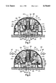
- FIG. 2 is a cross-sectional view of the shock sensor of FIG. 1 not undergoing any acceleration.
- FIG. 3 is a cross-sectional view of the shock sensor of FIG. 1 undergoing acceleration.
- FIG. 4 is a cross-sectional view of the shock sensor of FIG. 2 taken along section line 4--4.
- FIG. 5 is a cross-sectional view of an alternative embodiment shock sensor of this invention not undergoing acceleration.
- FIG. 6 is a cross-sectional view of the shock sensor of FIG. 5 undergoing acceleration showing an alternative, adjustable, spring mount.
- FIG. 7 is a fragmentary cross-sectional view of yet another embodiment of the shock sensor of this invention where opposed magnets are used instead of springs.
- FIG. 8 is a fragmentary cross-sectional view of still another embodiment of the shock sensor of this invention where a single large spring is used between the carriage and the housing.
- FIG. 9 is a horizontal cross-sectional view of yet another embodiment of the shock sensor of this invention wherein the carriage is joined to the housing by nested gimbals.
- FIG. 10 is a cross-sectional view of yet another embodiment of this invention wherein a compressed bellows is used to bias and prevent rotation between the housing and the carriage.
- FIG. 11 is a horizontal cross-sectional view showing an alternative embodiment of FIG. 1 wherein multiple reed switches are employed for redundancy and directionality.
- a shock sensor 20 is shown in FIGS. 1, 2, 3 and 4.
- the shock sensor 21 has a reed switch 22 which is vertically mounted in a subframe 24 on a housing 26.
- the reed switch 22 is conventional, having two reeds 28 sealed in a glass capsule 30. The reeds 28 react to the presence of a magnetic field by contacting each other, as shown in FIG. 3, so closing a circuit.
- the multi-directional shock sensor 20 has an actuating magnet 32 with a frustoconical interior aperture 34 which surrounds and is spaced about the subframe 24.
- the exterior of the magnet is generally frustoconical and tapers downwardly.
- the magnet 32 is connected to a carriage 36, for example, by a snap-fit engagement with the carriage.
- the magnet 32 actuates the reed switch 22 when it is tilted toward the reed switch 22.
- the carriage 36 is mounted to the housing 26 by a two-degree-of-freedom joint 38.
- the joint 38 in the embodiment of FIG. 1 is of the ball and socket type and is formed in part by a semi-spherical convex protrusion 40 at the base of the subframe 24.
- the carriage 36 has downwardly extending frustoconical portions which define a hollow cup 42 within which is mounted the magnet 32.
- the cup has a base 44 with a central aperture 46 defined by a surrounding annulus 48.
- the annulus 48 defines a narrow semi-spherical concave surface which rides on the semi-spherical protrusion 40, thus forming the joint 38.
- the annulus 48 of the carriage cup base riding on the semi-spherical base 41) of the subframe 24 allows the cartage 36 to tilt relative to the subframe 24 and the reed switch 22 mounted therein.
- the carriage 36 is able to tilt in all directions about the point of concentricity 50.
- a shell 52 is mounted to the housing 26 and encloses the carriage 36.
- the shell 52 has an inside concave semi-spherical surface 54 which is concentric with the semi-spherical subframe base 40 and the annulus 48 in the base 44 of the carriage cup 42.
- the carriage 36 is captured between the housing and the shell such that the carriage base annulus 48 is constrained to ride on the semi-spherical base protrusion 40 of the subframe 24.
- the carriage includes four ball beatings 56 which ride on the inside surface 54 of the shell 52.
- the ball bearings are engaged against and bear on ball bearing cups 58 which are formed into a peripheral lip 60 which extends outwardly from the upper edge 62 of the carriage cup 42.
- the ball bearings 56 are spaced at 90° intervals within the ball bearing cups 58 in the upper edge 64 of the lip 60 of the carriage 36.
- Downwardly protruding cones 66 extend from the carriage lip 60 beneath the ball bearing cups 58 on the bottom 65 of the lip 60.
- the cones 66 are surrounded by depressions 68 which serve to retain coil springs 70.
- the springs 70 are retained on the base 71 of the housing 26 by cones 72 which extend upwardly from the housing.
- the housing cones 72 are surrounded by depressions 74.
- the four equally spaced springs 70 are held between the carriage cones 66 and the housing cones 72. The springs 70 bias the carriage 36 to an upright position centered about the subframe 24.
- the multi-directional shock sensor 20 may be conveniently mounted to a circuit board 76 by screws 78 in screw mounts 80.
- the shock sensor 20 in a preferred embodiment is approximately one inch to three-quarters of an inch across.
- the shock sensor 20 has leads 82 which protrude to the circuit board 76 where they are soldered by solder joints 84 to circuit traces (not shown) in a conventional manner such as by wave soldering.
- the multi-directional shock sensor 20 is a micro-electronic device which can be integrated onto a circuit board which contains other electronic components which detect the closing of the reed switch and amplify, condition, and sustain the signal produced by the reed switch to actuate a safety device such as an airbag by initiating a gas generator cartridge that fills the airbag, or by turning on a transmitter to broadcast a distress signal such as used by downed airplanes.
- a safety device such as an airbag by initiating a gas generator cartridge that fills the airbag, or by turning on a transmitter to broadcast a distress signal such as used by downed airplanes.
- the shock sensor 20 functions as shown in HG. 3 by responding to an acceleration in a given direction indicated by arrows 87.
- the magnet 32 functions as an acceleration-sensing mass which is fixed to the carriage and hence constrained by the annulus 48 riding on the semi-spherical protrusion 40 of the subframe 24 and the ball beatings 56 tiding on the inside surface 54 of the shell.
- the magnet 32 responds to forces produced by an acceleration by tilting within the housing 26. This tilting brings the magnet 32 adjacent to the subframe 24 which actuates the reed switch 22 contained therein.
- a tether 86 joins the carriage 36 to the housing 26.
- the tether 86 is a metallic spring element which is very flexible in two planes but resists extension.
- the attachment point 88 to the housing 26 is spaced 180° from the attachment point 90 on the carriage 36 and passes through a retention loop 92 which extends from the carriage at 90° from the housing attachment point 88.
- the tether 86 may readily twist or bend depending on the orientation of the acceleration which the sensor 20 is exposed to.
- the design of the tether 86 is such that little resistance to bending or torsion is provided by the tether 86. However, for the carriage 36 to rotate with respect to the housing 26 would require the tether to extend or be compressed, to which the tether is resistant, thus preventing undesirable rotation about the axis 23 defined by the reed switch 22.
- the shell 52 may have a hermetic seal 94 where it is joined to the base 71 of the housing 26.
- the hermetic seal 94 seals the moving components of the shock sensor 20 from environmental contamination which might affect its reliability or functionality.
- the hermetic seal also allows the filling of the interior void 96 with a fluid such as an inert gas or oil. Filling the interior void 96 with oil could be used to increase the damping characteristics of the shock sensor 20.
- a dense fluid to fill the interior void 96 of the shock sensor 20 would allow the use of floats positioned beneath the bottom 65 of the lip 60 to provide the vertical restoring force on the carriage 36.
- the shell 52 has a centrally located depression 98 which receives the top 100 of the subframe 24 which thus reinforces and rigidities both the shell 52 and the subframe 24.
- a flat ring surface 102 spaced around the depression 98 functions as a stop for the carriage 36 where the top 104 of the magnet 32 abuts the ring surface 102, thus preventing the magnet 32 and the attached carriage 36 from impacting the subframe 24.
- An alternative multi-directional shock sensor 20 may be constructed to operate without ball beatings 56 where the sliding surfaces on the upper edge of the lip 64 are brought into contact with the inside surface 54 of the shell 52. Where sliding contacts are used, such as between surface 106 and the shell inner surface 54 or the contact between the annulus 48 and the semi-spherical base 40 of the subframe 24, materials with selected coefficients of friction will be chosen to produce the appropriate amount of damping.
- the shock sensor 20 may be modified to form the alternative embodiment shock sensor 120 shown in FIG. 11 in which the central reed switch 22 is replaced by multiple reed switches 122.
- the use of multiple reed switches 122 in the shock sensor 120 enables a determination of the directionality of the shock by analyzing which reed switches are actuated in what order.
- the interior surface 135 of the aperture 134 of the magnet 132 which is mounted on the carriage 136, will approach the subframe 124 and will cause the reed switch 122 closest to the magnet 134 to close first, thus indicating at least the quadrant in which the source of acceleration or crash originates.
- the reed switches 122 and the shock sensor 120 will preferably be oriented such that one reed switch corresponds to the front quadrant of the car, one reed switch to the rear, one to the left, and one to the right side.
- safety equipment such as a deployable airbag, might in some circumstances not be activated in response to a rear crash, but would be activated in a head-on collision.
- the shock sensor 120 may be able to differentiate between a crash where fuel valves should be shut off and a mid-air collision, where shut-down of the engines may be undesirable.
- the shock sensor 220 has an acceleration-sensing mass which is distinct from the actuation magnet.
- the shock sensor 220 has a reed switch 222, defining an axis 223, which is mounted on a subframe 224 which in turn extends upwardly from a housing 226.
- a carriage 236 is mounted to the housing 226 and has an aperture 246 defined by an annulus 248 which bears on the semi-spherical protrusion 240 of the subframe 224.
- the carriage 236 is captured by a shell 252 similar to the shell 52.
- the reed switch 222 has a frustoconical acceleration sensing mass 231 which is concentrically attached to an upwardly opening cup 242 formed by the carriage but extends only about halfway down into the cup.
- the acceleration sensing mass 231 has a top 304 which abuts a flat surface 302 at the top of the shell 252 in the carriage fully tilted position. Beneath the top 304 of the conical mass 231 is a bottom surface 233.
- the bottom surface 233 is spaced from the base 244 of the carriage 236 cup 242.
- a cylindrical magnet 237 is supported on the base 244 of the cup 242 adjacent to the annulus 248 defined by aperture 246 in the base 244 which surrounds the subframe 224.
- the cylindrical magnet 237 has a height nearly equal to the distance between the base 244 of the cup 242 and the bottom surface 233 of the conical mass 231.
- the cylindrical magnet 237 surrounds the subframe 224 and is slidable vertically thereon.
- the lower surface 239 of the cylindrical magnet 237 which rests on the base 244 has a small annular notch 243 which extends upwardly from the lower surface 239 to the inside cylindrical surface 241.
- the notch 243 provides clearance for the semi-spherical protruding base 240 of the subframe 224.
- the magnet 237 has a height such that the upper surface 245 of the magnet just slightly underlies the bottom surface 233 of the acceleration sensing mass 231. Thus, the magnet 237 is captured between the base 244 and the bottom surface 233 of the acceleration sensing mass 231. A small gap is left between the upper surface 245 of the cylindrical magnet 237 and the bottom surface 233 of the sensing mass 231 to allow for the downward slope of the surface 233 when it overlies the magnet 237 as the carriage 236 is tilted in response to an acceleration indicated by arrow 287 in FIG. 6.
- the shock sensor 220 is shown in FIG. 6 in the actuated position with the carriage 236 tilted about the point of concentricity 250.
- the tilting of the cup 242 which is in engagement with the lower surface 239 of the cylindrical magnet, causes it to move upward along the subframe 224.
- This upward displacement of the cylindrical magnet causes the reed switch 222 to activate.
- the cylindrical magnet 237 has an outside diameter sized to assure that it is at all times captive between the bottom surface 233 of the conical mass and the base 244 of the cup 242.
- a cone 266 and its surrounding depression 268 for retaining a spring 270 is shown threadedly engaged with the base 271 of the housing.
- the cone 266 has a screw socket 273 for an allen wrench such that the cone 266 and its surrounding depression 268 may be elevated or retracted to adjust the tension on the spring 270.
- Springs can be difficult to manufacture to tight tolerances and when they are used in opposed pairs, it can sometimes be desirable to match them or to provide a mechanism for adjusting the relative tension on each spring. Such a mechanism is provided by the threaded attachment of the spring mount 269.
- shock sensor 20 of this invention is shown in FIG. 7.
- the shock sensor 320 has opposed upper magnets 321 and lower magnets 323.
- the upper magnets 321 are rigidly mounted to a carriage 336 and the lower magnets 323 are rigidly mounted to the base 37 1 of the housing 326.
- the like poles of the upper magnets 321 and the lower magnets 323 are opposed, thus causing the upper magnets 321 to repel the lower magnets 323 and provide the restorative force to keep the carriage 336 centered about the reed switch 322.
- shock sensor 420 is shown in FIG. 8.
- the shock sensor has a single coil spring 470 which is fixed between the bottom lip 465 of the carriage 436 and the base 471 of the housing 426.
- the spring 470 provides a somewhat more uniform force for restoring and biasing the carriage 436 into an upright position about the subframe 424.
- FIG. 9 A horizontal cross-section of an alternative shock sensor 520 employing a gimbal mount 521 is shown in FIG. 9.
- the shock sensor 520 employs a two-degree-of-freedom universal joint formed by the gimbal 521 which is inherently resistant to rotation and so does not require a tether.
- the gimbal ring has an outer gimbal ring 523 and an inner gimbal ring 525.
- the outer gimbal ring 523 is rigidly mounted to the base 57 1 of the housing 526.
- the outer gimbal 523 is joined to the inner gimbal ring 525 by opposed outer hinges 527.
- the inner gimbal ring in turn has inner opposed hinges 529 which are joined to the base 544 of the cup 542 of the carriage 536.
- a spring (not shown for clarity) may be mounted between the outer gimbal ring 523 and the upper lip (not shown) of the carriage 536.
- the gimbal mechanism 521 is similar to those typically used in the aircraft industry for supporting rate gyros. It may be readily formed by electro-discharge machining or photo-etching from a sheet of spring steel. Thus, the outer gimbal ring 521, the outer hinges 527, the inner gimbal ring 528, and the inner hinges 529 may be integrally formed. The two sets of hinges 527, 529, because they are located in planes spaced 90° apart, allow the carriage 536 to be tilted in any direction about the subframe 524.
- FIG. 10 Another alternative embodiment shock sensor 620, shown in FIG. 10, eliminates the requirement for the tether 86 shown in FIGS. 1, 4, and 11 by utilizing a spring bellows 670.
- the biasing springs 70 of FIG. 1 are replaced by a spring bellows 670 which is fixed between the bottom lip 665 of the carriage 636 and the base 67 1 of the housing 626.
- the spring bellows 670 provides a somewhat more uniform force for restoring and biasing the carriage 636 into an upright position about the subframe 624 and resists rotation of the carriage 636.
- the carriage and shell of any of the embodiments of the shock sensor of this invention may further be configured to be non-symmetrical about the reed switch axis.
- the shell may have protrusions formed therein which interfere with the tilting of the carriage in that direction.
- adjustable spring mounts 269 such as shown in FIG. 6 could be used.
- magnet 32 which also functions as an acceleration sensing mass
- the function could be broken up into two pans which would include a magnet mounted to the carriage 36 and a separate mass mounted to the carriage 36.
- magnet is shown as a solid unit, it could be composed of discrete magnets mounted on the carriage 36 and spaced about the central subframe 24.
- shock sensors 20, 220, 320, 420, 620 are shown mounted to a circuit board, they could be mounted directly to the structure of a vehicle with leads running to detecting circuitry at some distance from the shock sensor.
- shock sensor 120 is shown to have four central reed switches, two or more switches could be employed.
- the travel range in any direction of the shock sensors 20, 120, 220, 320, 420, 520, 620 can be adjusted to remove sensitivity to impact or oscillation along a particular axis.
Abstract
Description
Claims (29)
Priority Applications (4)
| Application Number | Priority Date | Filing Date | Title |
|---|---|---|---|
| US08/124,267 US5378865A (en) | 1993-09-20 | 1993-09-20 | Multi-directional shock sensor |
| DE69409750T DE69409750T2 (en) | 1993-09-20 | 1994-09-14 | Shock sensor sensitive in several directions |
| EP94306752A EP0650061B1 (en) | 1993-09-20 | 1994-09-14 | Multi-directional shock sensor |
| JP6224932A JP2634568B2 (en) | 1993-09-20 | 1994-09-20 | Multi-directional shock sensor |
Applications Claiming Priority (1)
| Application Number | Priority Date | Filing Date | Title |
|---|---|---|---|
| US08/124,267 US5378865A (en) | 1993-09-20 | 1993-09-20 | Multi-directional shock sensor |
Publications (1)
| Publication Number | Publication Date |
|---|---|
| US5378865A true US5378865A (en) | 1995-01-03 |
Family
ID=22413829
Family Applications (1)
| Application Number | Title | Priority Date | Filing Date |
|---|---|---|---|
| US08/124,267 Expired - Fee Related US5378865A (en) | 1993-09-20 | 1993-09-20 | Multi-directional shock sensor |
Country Status (4)
| Country | Link |
|---|---|
| US (1) | US5378865A (en) |
| EP (1) | EP0650061B1 (en) |
| JP (1) | JP2634568B2 (en) |
| DE (1) | DE69409750T2 (en) |
Cited By (12)
| Publication number | Priority date | Publication date | Assignee | Title |
|---|---|---|---|---|
| US5548377A (en) * | 1994-04-19 | 1996-08-20 | Fuji Xerox Co., Ltd. | Method of controlling an image forming apparatus when an emergency stop signal is generated |
| DE19629994C1 (en) * | 1996-07-25 | 1997-10-09 | Telefunken Microelectron | Acceleration switch esp. for triggering motor vehicle occupant restraint system |
| US5828138A (en) * | 1996-12-02 | 1998-10-27 | Trw Inc. | Acceleration switch |
| US5955714A (en) * | 1998-05-20 | 1999-09-21 | Breed Technologies, Inc. | Roll-over shunt sensor |
| US6018130A (en) * | 1998-05-20 | 2000-01-25 | Breed Automotive Technology, Inc. | Roll-over sensor with pendulum mounted magnet |
| KR20000057565A (en) * | 1996-12-17 | 2000-09-25 | 드레이어 론니 알 | Glass capsule enclosed shock sensor |
| US7030777B1 (en) | 2001-11-06 | 2006-04-18 | Logic Systems, Inc. | Roadway incursion alert system |
| US7230546B1 (en) | 2001-11-06 | 2007-06-12 | Craig Nelson | Roadway incursion alert system |
| US20100253530A1 (en) * | 2008-04-09 | 2010-10-07 | Industrial Technology Research Institute | All-directional fall sensor |
| US10123582B2 (en) | 2013-06-26 | 2018-11-13 | I1 Sensortech, Inc. | Flexible impact sensor for use with a headpiece |
| US10132894B2 (en) | 2012-01-11 | 2018-11-20 | Schlumberger Technology Corporation | Magnetic resonance imaging methods |
| US10866259B1 (en) * | 2017-08-17 | 2020-12-15 | Tozuda, LLC | Impact sensor |
Families Citing this family (1)
| Publication number | Priority date | Publication date | Assignee | Title |
|---|---|---|---|---|
| ES2155794B1 (en) * | 1999-07-15 | 2001-12-01 | Univ Valladolid | SYSTEM FOR AUTOMATIC GUIDING OF VEHICLES IN A CONTROLLED ENVIRONMENT. |
Citations (11)
| Publication number | Priority date | Publication date | Assignee | Title |
|---|---|---|---|---|
| US4016535A (en) * | 1975-12-15 | 1977-04-05 | Sheller-Globe Corporation | Tilt alarm for tractor vehicle or the like |
| US4705922A (en) * | 1986-06-10 | 1987-11-10 | Hengstler Bauelemente Gmbh | Relay for the operation of a belt tightener or tensioner for automobile safety belts |
| US4916266A (en) * | 1989-06-08 | 1990-04-10 | Aerodyne Controls Corporation | Miniature omnidirectional instantly responsive impact switch |
| US4982684A (en) * | 1989-05-30 | 1991-01-08 | Detectors, Inc. | Directional shock detector |
| US4987276A (en) * | 1988-09-09 | 1991-01-22 | Audi Ag | Deceleration switch |
| US5149926A (en) * | 1989-11-08 | 1992-09-22 | Nippon Seiko Kabushiki Kaisha | Acceleration sensor |
| US5153394A (en) * | 1990-06-29 | 1992-10-06 | Robert Bosch Gmbh | Tilt-actuated switch |
| US5165717A (en) * | 1990-08-09 | 1992-11-24 | Nissan Motor Co., Ltd. | Airbag sensor for airbag restraint system |
| US5194706A (en) * | 1991-08-14 | 1993-03-16 | Hamlin, Inc. | Shock sensor with a magnetically operated reed switch |
| US5212357A (en) * | 1991-08-14 | 1993-05-18 | Hamlin, Inc. | Extended minimum dwell shock sensor |
| GB2263580A (en) * | 1992-01-17 | 1993-07-28 | Hamlin Electronics Europ Ltd | A switch assembly |
Family Cites Families (2)
| Publication number | Priority date | Publication date | Assignee | Title |
|---|---|---|---|---|
| DE4129801A1 (en) * | 1991-09-07 | 1993-03-11 | Bosch Gmbh Robert | SENSOR FOR AUTOMATIC TRIGGERING OF SAFETY DEVICES IN MOTOR VEHICLES |
| DE4202418A1 (en) * | 1992-01-29 | 1993-08-05 | Bosch Gmbh Robert | Acceleration sensor for triggering vehicle passenger safety devices - contains switching magnets, at least one fixed and one spring suspended, and magnetic field sensitive reed switch |
-
1993
- 1993-09-20 US US08/124,267 patent/US5378865A/en not_active Expired - Fee Related
-
1994
- 1994-09-14 EP EP94306752A patent/EP0650061B1/en not_active Expired - Lifetime
- 1994-09-14 DE DE69409750T patent/DE69409750T2/en not_active Expired - Fee Related
- 1994-09-20 JP JP6224932A patent/JP2634568B2/en not_active Expired - Fee Related
Patent Citations (11)
| Publication number | Priority date | Publication date | Assignee | Title |
|---|---|---|---|---|
| US4016535A (en) * | 1975-12-15 | 1977-04-05 | Sheller-Globe Corporation | Tilt alarm for tractor vehicle or the like |
| US4705922A (en) * | 1986-06-10 | 1987-11-10 | Hengstler Bauelemente Gmbh | Relay for the operation of a belt tightener or tensioner for automobile safety belts |
| US4987276A (en) * | 1988-09-09 | 1991-01-22 | Audi Ag | Deceleration switch |
| US4982684A (en) * | 1989-05-30 | 1991-01-08 | Detectors, Inc. | Directional shock detector |
| US4916266A (en) * | 1989-06-08 | 1990-04-10 | Aerodyne Controls Corporation | Miniature omnidirectional instantly responsive impact switch |
| US5149926A (en) * | 1989-11-08 | 1992-09-22 | Nippon Seiko Kabushiki Kaisha | Acceleration sensor |
| US5153394A (en) * | 1990-06-29 | 1992-10-06 | Robert Bosch Gmbh | Tilt-actuated switch |
| US5165717A (en) * | 1990-08-09 | 1992-11-24 | Nissan Motor Co., Ltd. | Airbag sensor for airbag restraint system |
| US5194706A (en) * | 1991-08-14 | 1993-03-16 | Hamlin, Inc. | Shock sensor with a magnetically operated reed switch |
| US5212357A (en) * | 1991-08-14 | 1993-05-18 | Hamlin, Inc. | Extended minimum dwell shock sensor |
| GB2263580A (en) * | 1992-01-17 | 1993-07-28 | Hamlin Electronics Europ Ltd | A switch assembly |
Cited By (13)
| Publication number | Priority date | Publication date | Assignee | Title |
|---|---|---|---|---|
| US5548377A (en) * | 1994-04-19 | 1996-08-20 | Fuji Xerox Co., Ltd. | Method of controlling an image forming apparatus when an emergency stop signal is generated |
| DE19629994C1 (en) * | 1996-07-25 | 1997-10-09 | Telefunken Microelectron | Acceleration switch esp. for triggering motor vehicle occupant restraint system |
| US5828138A (en) * | 1996-12-02 | 1998-10-27 | Trw Inc. | Acceleration switch |
| KR20000057565A (en) * | 1996-12-17 | 2000-09-25 | 드레이어 론니 알 | Glass capsule enclosed shock sensor |
| US5955714A (en) * | 1998-05-20 | 1999-09-21 | Breed Technologies, Inc. | Roll-over shunt sensor |
| US6018130A (en) * | 1998-05-20 | 2000-01-25 | Breed Automotive Technology, Inc. | Roll-over sensor with pendulum mounted magnet |
| US7030777B1 (en) | 2001-11-06 | 2006-04-18 | Logic Systems, Inc. | Roadway incursion alert system |
| US7230546B1 (en) | 2001-11-06 | 2007-06-12 | Craig Nelson | Roadway incursion alert system |
| US20100253530A1 (en) * | 2008-04-09 | 2010-10-07 | Industrial Technology Research Institute | All-directional fall sensor |
| US8028643B2 (en) * | 2008-04-09 | 2011-10-04 | Industrial Technology Research Institute | All-directional fall sensor |
| US10132894B2 (en) | 2012-01-11 | 2018-11-20 | Schlumberger Technology Corporation | Magnetic resonance imaging methods |
| US10123582B2 (en) | 2013-06-26 | 2018-11-13 | I1 Sensortech, Inc. | Flexible impact sensor for use with a headpiece |
| US10866259B1 (en) * | 2017-08-17 | 2020-12-15 | Tozuda, LLC | Impact sensor |
Also Published As
| Publication number | Publication date |
|---|---|
| JPH07198739A (en) | 1995-08-01 |
| EP0650061A1 (en) | 1995-04-26 |
| DE69409750T2 (en) | 1998-09-17 |
| EP0650061B1 (en) | 1998-04-22 |
| DE69409750D1 (en) | 1998-05-28 |
| JP2634568B2 (en) | 1997-07-30 |
Similar Documents
| Publication | Publication Date | Title |
|---|---|---|
| US5378865A (en) | Multi-directional shock sensor | |
| US4900880A (en) | Gas damped crash sensor | |
| US7351925B2 (en) | Method and apparatus for detecting free fall | |
| US3835273A (en) | Pendulum-type inertia sensor switch | |
| US6139053A (en) | Single point acceleration sensor | |
| CA2196504A1 (en) | Acceleration sensor for a vehicle for detecting an acceleration in a predetermined direction | |
| US4022998A (en) | Acceleration and retardation responsive electric control device | |
| US5029473A (en) | Acceleration sensor | |
| JP2006317171A (en) | Inclination sensor | |
| US4900925A (en) | Acceleration sensor pick-up with magnetic base stabilization | |
| US4266107A (en) | Acceleration switch | |
| US4898033A (en) | Acceleration sensor | |
| JP3215500U (en) | In-vehicle tilt detector | |
| EP0055389B1 (en) | Locking device reacting to inertia forces for retractors | |
| CN111356615A (en) | Sensor for actuating a sensitive locking mechanism of a vehicle of a belt retractor | |
| US5178410A (en) | Velocity change sensor with lateral shock absorber | |
| KR100502454B1 (en) | Acceleration detecting device | |
| US5017743A (en) | Gas damped deceleration switch | |
| JP2692222B2 (en) | Seismic sensor | |
| US5118908A (en) | Gas damped deceleration switch | |
| JP2692221B2 (en) | Seismic sensor | |
| JP2692220B2 (en) | Seismic sensor with horizontal holding mechanism | |
| JP3052416B2 (en) | Seismic sensor | |
| JP4005561B2 (en) | Fall detection device | |
| KR100210931B1 (en) | Side air bag sensor |
Legal Events
| Date | Code | Title | Description |
|---|---|---|---|
| AS | Assignment |
Owner name: HAMLIN, INC., WISCONSIN Free format text: ASSIGNMENT OF ASSIGNORS INTEREST;ASSIGNOR:RENEAU, DANIEL R.;REEL/FRAME:006822/0906 Effective date: 19930920 |
|
| AS | Assignment |
Owner name: BREED AUTOMOTIVE TECHNOLOGIES, INC., FLORIDA Free format text: ASSIGNMENT OF ASSIGNORS INTEREST;ASSIGNOR:HAMLIN INCORPORATED;REEL/FRAME:008194/0503 Effective date: 19961022 |
|
| FEPP | Fee payment procedure |
Free format text: PAYOR NUMBER ASSIGNED (ORIGINAL EVENT CODE: ASPN); ENTITY STATUS OF PATENT OWNER: LARGE ENTITY |
|
| AS | Assignment |
Owner name: NATIONSBANK, NATIONAL ASSOCIATION, AS AGENT, NORTH Free format text: SECURITY AGREEMENT;ASSIGNOR:BREED AUTOMOTIVE TECHNOLOGY, INC.;REEL/FRAME:008783/0810 Effective date: 19971030 |
|
| FPAY | Fee payment |
Year of fee payment: 4 |
|
| AS | Assignment |
Owner name: CONGRESS FINANCIAL CORPORATION (FLORIDA), FLORIDA Free format text: SECURITY INTEREST;ASSIGNOR:BREED AUTOMOTIVE TECHNOLOGY, INC.;REEL/FRAME:011442/0646 Effective date: 20001226 |
|
| FPAY | Fee payment |
Year of fee payment: 8 |
|
| AS | Assignment |
Owner name: BREED AUTOMOTIVE TECHNOLOGY, INC., MICHIGAN Free format text: RELEASE OF SECURITY INTEREST IN TRADEMARKS;ASSIGNOR:CONGRESS FINANCIAL CORPORATION;REEL/FRAME:014313/0243 Effective date: 20030725 |
|
| AS | Assignment |
Owner name: CITICORP USA, INC., AS TERM C LOAN COLLATERAL AGEN Free format text: SECURITY AGREEMENT;ASSIGNOR:BREED AUTOMOTIVE TECHNOLOGY, INC.;REEL/FRAME:014428/0283 Effective date: 20030425 |
|
| AS | Assignment |
Owner name: KEY SAFETY SYSTEMS, INC., MICHIGAN Free format text: ASSIGNMENT OF ASSIGNORS INTEREST;ASSIGNOR:BREED AUTOMOTIVE TECHNOLOGY, INC.;REEL/FRAME:015312/0643 Effective date: 20041029 |
|
| REMI | Maintenance fee reminder mailed | ||
| LAPS | Lapse for failure to pay maintenance fees | ||
| STCH | Information on status: patent discontinuation |
Free format text: PATENT EXPIRED DUE TO NONPAYMENT OF MAINTENANCE FEES UNDER 37 CFR 1.362 |
|
| FP | Lapsed due to failure to pay maintenance fee |
Effective date: 20070103 |
|
| AS | Assignment |
Owner name: CITICORP USA, INC., NEW YORK Free format text: SECURITY AGREEMENT;ASSIGNORS:KEY SAFETY SYSTEMS, INC;KSS HOLDINGS, INC;KSS ACQUISITION COMPANY;AND OTHERS;REEL/FRAME:019297/0249 Effective date: 20070308 Owner name: CITICORP USA, INC.,NEW YORK Free format text: SECURITY AGREEMENT;ASSIGNORS:KEY SAFETY SYSTEMS, INC;KSS HOLDINGS, INC;KSS ACQUISITION COMPANY;AND OTHERS;REEL/FRAME:019297/0249 Effective date: 20070308 |