US5382799A - Ultraviolet intensity meter - Google Patents
Ultraviolet intensity meter Download PDFInfo
- Publication number
- US5382799A US5382799A US08/170,083 US17008393A US5382799A US 5382799 A US5382799 A US 5382799A US 17008393 A US17008393 A US 17008393A US 5382799 A US5382799 A US 5382799A
- Authority
- US
- United States
- Prior art keywords
- ultraviolet
- electronic circuit
- microprocessor
- analog
- digital value
- Prior art date
- Legal status (The legal status is an assumption and is not a legal conclusion. Google has not performed a legal analysis and makes no representation as to the accuracy of the status listed.)
- Expired - Lifetime
Links
- 238000005259 measurement Methods 0.000 claims abstract description 41
- 238000009781 safety test method Methods 0.000 abstract description 5
- 230000007613 environmental effect Effects 0.000 abstract description 4
- 230000000994 depressogenic effect Effects 0.000 abstract description 3
- 239000004973 liquid crystal related substance Substances 0.000 abstract description 2
- 238000001723 curing Methods 0.000 description 22
- 229920000642 polymer Polymers 0.000 description 5
- 230000006870 function Effects 0.000 description 4
- 230000004048 modification Effects 0.000 description 4
- 238000012986 modification Methods 0.000 description 4
- 230000003750 conditioning effect Effects 0.000 description 3
- 238000013461 design Methods 0.000 description 3
- 238000010586 diagram Methods 0.000 description 3
- 239000000178 monomer Substances 0.000 description 3
- 230000003287 optical effect Effects 0.000 description 3
- 238000006116 polymerization reaction Methods 0.000 description 3
- 238000003908 quality control method Methods 0.000 description 3
- 229920006362 Teflon® Polymers 0.000 description 2
- 238000006243 chemical reaction Methods 0.000 description 2
- 230000010354 integration Effects 0.000 description 2
- 238000004519 manufacturing process Methods 0.000 description 2
- 125000006850 spacer group Chemical group 0.000 description 2
- 239000000126 substance Substances 0.000 description 2
- 230000003213 activating effect Effects 0.000 description 1
- 230000004913 activation Effects 0.000 description 1
- 230000015556 catabolic process Effects 0.000 description 1
- 239000003054 catalyst Substances 0.000 description 1
- 230000007423 decrease Effects 0.000 description 1
- 238000006731 degradation reaction Methods 0.000 description 1
- 239000000835 fiber Substances 0.000 description 1
- 239000011521 glass Substances 0.000 description 1
- 239000003999 initiator Substances 0.000 description 1
- 230000000977 initiatory effect Effects 0.000 description 1
- 238000003780 insertion Methods 0.000 description 1
- 230000037431 insertion Effects 0.000 description 1
- 238000002955 isolation Methods 0.000 description 1
- 230000013011 mating Effects 0.000 description 1
- 230000005499 meniscus Effects 0.000 description 1
- 238000000034 method Methods 0.000 description 1
- 238000012544 monitoring process Methods 0.000 description 1
- 238000000016 photochemical curing Methods 0.000 description 1
- 238000006552 photochemical reaction Methods 0.000 description 1
- 230000008439 repair process Effects 0.000 description 1
- 230000004044 response Effects 0.000 description 1
- 238000005096 rolling process Methods 0.000 description 1
- 239000007787 solid Substances 0.000 description 1
- 210000003813 thumb Anatomy 0.000 description 1
- 238000011179 visual inspection Methods 0.000 description 1
Images


Classifications
-
- G—PHYSICS
- G01—MEASURING; TESTING
- G01J—MEASUREMENT OF INTENSITY, VELOCITY, SPECTRAL CONTENT, POLARISATION, PHASE OR PULSE CHARACTERISTICS OF INFRARED, VISIBLE OR ULTRAVIOLET LIGHT; COLORIMETRY; RADIATION PYROMETRY
- G01J1/00—Photometry, e.g. photographic exposure meter
- G01J1/02—Details
-
- G—PHYSICS
- G01—MEASURING; TESTING
- G01J—MEASUREMENT OF INTENSITY, VELOCITY, SPECTRAL CONTENT, POLARISATION, PHASE OR PULSE CHARACTERISTICS OF INFRARED, VISIBLE OR ULTRAVIOLET LIGHT; COLORIMETRY; RADIATION PYROMETRY
- G01J1/00—Photometry, e.g. photographic exposure meter
- G01J1/02—Details
- G01J1/0247—Details using a charging unit
-
- G—PHYSICS
- G01—MEASURING; TESTING
- G01J—MEASUREMENT OF INTENSITY, VELOCITY, SPECTRAL CONTENT, POLARISATION, PHASE OR PULSE CHARACTERISTICS OF INFRARED, VISIBLE OR ULTRAVIOLET LIGHT; COLORIMETRY; RADIATION PYROMETRY
- G01J1/00—Photometry, e.g. photographic exposure meter
- G01J1/02—Details
- G01J1/0271—Housings; Attachments or accessories for photometers
-
- G—PHYSICS
- G01—MEASURING; TESTING
- G01J—MEASUREMENT OF INTENSITY, VELOCITY, SPECTRAL CONTENT, POLARISATION, PHASE OR PULSE CHARACTERISTICS OF INFRARED, VISIBLE OR ULTRAVIOLET LIGHT; COLORIMETRY; RADIATION PYROMETRY
- G01J1/00—Photometry, e.g. photographic exposure meter
- G01J1/02—Details
- G01J1/04—Optical or mechanical part supplementary adjustable parts
- G01J1/0407—Optical elements not provided otherwise, e.g. manifolds, windows, holograms, gratings
- G01J1/0474—Diffusers
-
- G—PHYSICS
- G01—MEASURING; TESTING
- G01J—MEASUREMENT OF INTENSITY, VELOCITY, SPECTRAL CONTENT, POLARISATION, PHASE OR PULSE CHARACTERISTICS OF INFRARED, VISIBLE OR ULTRAVIOLET LIGHT; COLORIMETRY; RADIATION PYROMETRY
- G01J1/00—Photometry, e.g. photographic exposure meter
- G01J1/42—Photometry, e.g. photographic exposure meter using electric radiation detectors
- G01J1/429—Photometry, e.g. photographic exposure meter using electric radiation detectors applied to measurement of ultraviolet light
-
- G—PHYSICS
- G01—MEASURING; TESTING
- G01J—MEASUREMENT OF INTENSITY, VELOCITY, SPECTRAL CONTENT, POLARISATION, PHASE OR PULSE CHARACTERISTICS OF INFRARED, VISIBLE OR ULTRAVIOLET LIGHT; COLORIMETRY; RADIATION PYROMETRY
- G01J1/00—Photometry, e.g. photographic exposure meter
- G01J1/02—Details
- G01J2001/0276—Protection
- G01J2001/0285—Protection against laser damage
Definitions
- the present invention generally relates to instrumentation for taking measurements of the level of ultraviolet (UV) energy and, more particularly, to a portable UV intensity meter for measuring and displaying the intensity emitted by a UV light sources including, but not limited to, UV light sources used in spot curing systems.
- UV light sources including, but not limited to, UV light sources used in spot curing systems.
- UV spot curing systems typically include a source of high intensity UV light which may be turned on and off by the operator and a flexible light guide which emits a small spot of UV light. The free end of the flexible light guide is positioned close to the applied monomer, and the power to the UV light source is turned on to initiate the photochemical curing polymerization process.
- UV spot curing As UV spot curing has evolved, it has become increasingly important to establish a method of measuring system performance. Degradation of UV lamps, light guides, and reflectors can cause decreases in UV intensity and create curing problems. If the intensity of the UV light falls below a certain level, curing may not be complete resulting in a weak joint or attachment. Moreover, a visual inspection will not reveal the problem as the surface of the monomer spot may polymerize but the interior volume will not. It has therefore become mandatory, in certain applications to periodically measure the UV energy output of the spot curing system in order to insure that a sufficient UV intensity, is being delivered to the spot where curing is desired. However, such measurements are typically not conveniently made by current UV intensity measuring instruments and, due to the high output intensities of some spot curing systems, there is a risk that the output energy of the spot curing system will damage the measuring instrument.
- a self-contained, electro-optic instrument designed to measure and display the intensity emitted by a UV spot curing system.
- the instrument is a portable, battery-operated device which, in the preferred embodiment, has the size and shape of a flashlight.
- the measurement head receives various light guide adapters to provide a proper fit for a light guide of the UV spot curing system being used.
- the instrument is gripped in one hand while the light guide is inserted in the adapter in the measurement head with the other hand.
- a start switch on the body of the instrument is depressed and a measurement is taken.
- the start switch is released, the measurement temporarily stored and displayed on a display, such as a liquid crystal display (LCD).
- LCD liquid crystal display
- the instrument is capable of measuring very high intensities of UV energy (up to 19.99 W/cm 2 in a preferred implementation) without damage to the instrument.
- This is made possible by an attenuator plate between the light guide adapter and the input optics.
- the attenuator plate is provided with a very small hole or holes, the number and size of which depends the attenuation ratio desired. In a preferred implementation of the invention, the attenuation ratio is 100:1.
- the instrument can be configured to read one of the following UV bandwidths commonly used in spot curing systems: 250-260 nm, 280-320 nm, 320-390 nm, or 395-445 nm.
- the basic UV intensity. meter may be enhanced by providing a microprocessor and, optionally, a nonvolatile memory and clock.
- a microprocessor allows additional functions to be programmed into the instrument including an integration of intensity as a function of time to provide a readout of UV energy.
- the nonvolatile memory and clock it is possible to record time stamped intensity measurements made by the operator. This data can then be read out and analyzed at a later time for quality control purposes.
- FIGS. 1A and 1B are side elevations drawing of the preferred embodiment of the invention.
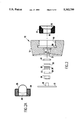
- FIG. 2 is an exploded view, partly in cross-section, of the measurement head of the instrument shown in FIG. 1;
- FIG. 2A is a cross-sectional view of an alternate fisheye lens insert for use in the measurement head of FIG. 2:
- FIG. 3 is a block diagram of the basic circuit of the preferred embodiment of the invention.
- FIG. 4 is a block diagram of the basic circuit enhanced with the addition of a microprocessor, nonvolatile memory and clock to provide additional programmable function and for use in quality control analysis.
- the instrument 10 has a shape similar to that of a conventional flashlight and comprises a generally cylindrical body 11 and a measurement head 12.
- the body 11 has a non-circular cross-section, such as a variant of an octagon, in order to prevent the instrument from rolling when placed on a surface near the operator.
- the measurement head 12, shown in more detail in FIG. 2 is provided in its face with an adapter to receive the light guide from the UV spot curing system. The operator typically holds the body 11 of the instrument in one hand and, with the other hand, inserts the light guide in the measurement head 12.
- the UV spot curing system is activated to generate its energy at the output end of the light guide and, at the same time, the start button 13 is depressed by the thumb of the hand holding the body 11.
- the reading is displayed on a display 14 conveniently located on an opposite or adjacent face of the body 11 from that of the start button 13, as shown in FIG. 1B. The reading is displayed for a period of perhaps two and one half minutes to allow the operator to read and note the measurement before continuing to operate the UV spot cure system.
- FIG. 2 shows an exploded view of the measurement head 12.
- the principle component is a solid machined body 15 having a threaded recess 16 for receiving an adapter 17 having mating threads.
- the adapter 17 has a bore 18 having an internal diameter depending on the outside diameter of a light guide for the particular LW spot curing system for which the measurement is desired.
- the bore 18 is provided with a tapered counter bore 19 having a diameter which increases toward the face of the measurement head.
- the adapter 17 may be provided with diametrically opposed slots (not shown) in its face end to allow easy removal and replacement with a screw driver or coin, thus allowing a single instrument to accommodate any diameter of light guide.
- groove 20 which receives an 0-ring (not shown) against which the adapter 17 abuts and into which the light guide is inserted to provide a substantially light-tight connection between the light guide and the measurement head.
- Opposite recess 16 is concentric recess 21 and a communicating bore 22 providing a through passage from the face to the rear of the measurement head 12.
- a groove 23 which receives an 0-ring 24.
- a diffuser window 25 one or more Teflon® diffusers 26
- an aperture plate 27 separated from the Teflon® diffuser 26 by an O-ring 28, a cut glass filter 29, and finally a spacer 30.
- This assembly is kept in place by a plate 31 having a central projection 32 which mates with the spacer 30.
- the plate 31 fits within a recess 33 machined in the rear of the measurement head 12 and is secured by screws (not shown).
- the projection 32 has a through bore which receives the UV detector mounted on a detector board (not shown). The size (and number) of the hole or holes in the aperture plate controls the amount of the UV light which reaches the UV detector.
- the aperture plate 27 which performs the function of a simple but effective optical attenuator, makes it possible to measure the intensity of very high output UV sources without damaging the UV detector.
- Such high output UV sources are characteristic of spot curing systems, for example, but for those applications where relatively low levels of UV light intensities are to be measured, the aperture plate 27 may be omitted.
- the instrument is provided with a fisheye (i.e., very wide angle) lens adapter as shown in FIG. 2A.
- This adapter replaces the adapter 17 shown in FIG. 2 and comprises a body 34 having threads that mate with the threads of recess 16.
- the body 34 contains a fisheye lens, typically comprising a spherical focussing lens 35 and a correcting meniscus lens 36, to focus UV light over a wide angle onto the detector in projection 32.
- FIG. 3 shows the basic detector circuit.
- UV light enters the optical stack 37, comprising the components of the optical head 12 shown in FIG. 2 and/or 2A. and enters the detector 38 housed in projection 32.
- the detector 38 generates an electrical signal output proportional to the intensity of the UV light string it.
- This electrical signal is input to signal conditioning circuitry 39.
- the signal conditioning circuitry is of conventional design and includes, among other components, a level adjusting voltage divider and may additionally include an isolation or buffer amplifier.
- the output of the signal conditioning circuitry 39 is input to an analog-to-digital (A/D) converter 40.
- the A/D converter uses an input reference voltage from A/D reference 41 to convert the input analog signal to a digital value.
- This digital value is temporarily stored by sample-and-hold (S/H) circuit 42.
- S/H sample-and-hold
- the A/D converter 40 is of conventional design and may be implemented with a commercially available integrated circuit (IC) device, such as the MAX136 A/D converter manufactured by Maxim Integrated Products. This device incorporates the S/H circuit 42 so that only a single IC is required for both the A/D converter 40 and S/H circuit 42.
- IC integrated circuit
- a battery 44 connected to a power switching circuit 45. Normally, no power is supplied to the circuit in order to conserve the power of battery 44. However, when the switch 13 (shown in FIG. 1A) is pressed, the push to read circuit 46 detects this, activating timer 47 and S/H circuit 42. The timer 47 causes the power switching circuit 46 to temporarily supply power to the circuit so that a measurement is made, sampled and displayed. After a predetermined period of time, as determined by timer 47, the power switching circuit reverts to a no power condition, blanking display 43.
- the circuit shown in FIG. 3 is quite sufficient for many applications where a simple intensity measurement is all that is required and where it is not necessary to generate a record of the measurements made. There are certain other applications where, in addition to an intensity measurement, it is desired to measure LrV energy and/or generate a time stamped record of measurements made. Such measurements and data records are possible with the modification of the basic device shown in FIG. 4, to which reference is now made.
- FIG. 4 is a block diagram showing an enhancement to the basic circuit.
- the output of A/D converter 40 instead of being supplied directly to display 43, is supplied to a microprocessor 48 controlled by a program stored in a Programmable Read Only Memory (PROM) 49.
- the program may cause the microprocessor 48 to activate the display 43 to first display the measured intensity of the UV light and then, after a predetermined time or in response to a second activation of the push to read circuit 46, display the UV energy.
- the UV energy is an integration of the intensity measurement over a period of time.
- the enhanced circuit may include a nonvolatile memory 50, such as an Electronically Erasable and Programmable Read Only Memory (E 2 PROM), and a real time clock 51.
- the program stored in PROM 49 causes the microprocessor 48 to format and store data corresponding to each measurement made with the instrument with a time stamp derived from clock 51 in the E 2 PROM 50.
- This record may be downloaded periodically to provide a Permanent record of measurements made. For example, where the instrument is used in a Production situation with a spot curing system, such a record may be advantageously used for quality control. Where the instrument is used in environmentally safety testing, such a record may be used to document the level of UV light measured in a work place.
Landscapes
- Physics & Mathematics (AREA)
- General Physics & Mathematics (AREA)
- Spectroscopy & Molecular Physics (AREA)
- Photometry And Measurement Of Optical Pulse Characteristics (AREA)
Abstract
A self-contained, electro-optic instrument measures and displays the intensity emitted by an ultraviolet (UV) light source. The instrument is a portable, battery-operated device which has the size and shape of a flashlight. The measurement head receives various light guide adapters to provide a proper fit for a light guide of the UV spot curing system being used. Alternatively, the measurement head may be fitted with a wide angle lens to receive UV light for environment safety testing. In operation with a spot curing system, the instrument is gripped in one hand while the light guide is inserted in the adapter in the measurement head with the other hand. Once the spot curing system's light guide is inserted, a start switch on the body of the instrument is depressed and a measurement is taken. When the start switch is released, the measurement temporarily stored and displayed on a display, such as a liquid crystal display (LCD). Operation is similar for environmental safety testing except the instrument is simply pointed in a direction where the UV light is to be measured.
Description
1. Field of the Invention
The present invention generally relates to instrumentation for taking measurements of the level of ultraviolet (UV) energy and, more particularly, to a portable UV intensity meter for measuring and displaying the intensity emitted by a UV light sources including, but not limited to, UV light sources used in spot curing systems.
2. Description of the Prior Art
There are many substances, known as monomers, which can be converted to polymers by chemical reactions. In some cases, these reactions are induced by chemical catalysts and initiators. However, polymerization can also be induced by supplying the initiation energy with visible or ultraviolet (UV) light. Such photochemical reactions have practical as well as theoretical advantages. For example, in certain manufacturing processes, a polymer may be used to secure parts of an assembly. In the field of fiber optics, splices and repairs are often made in the field using a polymer. In both of these examples, the photochemically induced polymerization is referred to as "curing".
Since there are many applications of UV cured polymers wherein the polymer is applied in only a small spot, there have been developed UV spot curing systems. These systems typically include a source of high intensity UV light which may be turned on and off by the operator and a flexible light guide which emits a small spot of UV light. The free end of the flexible light guide is positioned close to the applied monomer, and the power to the UV light source is turned on to initiate the photochemical curing polymerization process.
As UV spot curing has evolved, it has become increasingly important to establish a method of measuring system performance. Degradation of UV lamps, light guides, and reflectors can cause decreases in UV intensity and create curing problems. If the intensity of the UV light falls below a certain level, curing may not be complete resulting in a weak joint or attachment. Moreover, a visual inspection will not reveal the problem as the surface of the monomer spot may polymerize but the interior volume will not. It has therefore become mandatory, in certain applications to periodically measure the UV energy output of the spot curing system in order to insure that a sufficient UV intensity, is being delivered to the spot where curing is desired. However, such measurements are typically not conveniently made by current UV intensity measuring instruments and, due to the high output intensities of some spot curing systems, there is a risk that the output energy of the spot curing system will damage the measuring instrument.
It is therefore an object of the present invention to provide the operator of a UV spot curing system with instant feedback as to the performance of a spot curing system.
According to the invention, there is provided a self-contained, electro-optic instrument designed to measure and display the intensity emitted by a UV spot curing system. The instrument is a portable, battery-operated device which, in the preferred embodiment, has the size and shape of a flashlight. The measurement head receives various light guide adapters to provide a proper fit for a light guide of the UV spot curing system being used. In operation, the instrument is gripped in one hand while the light guide is inserted in the adapter in the measurement head with the other hand. Once the spot curing system's light guide is inserted, a start switch on the body of the instrument is depressed and a measurement is taken. When the start switch is released, the measurement temporarily stored and displayed on a display, such as a liquid crystal display (LCD).
The instrument is capable of measuring very high intensities of UV energy (up to 19.99 W/cm2 in a preferred implementation) without damage to the instrument. This is made possible by an attenuator plate between the light guide adapter and the input optics. The attenuator plate is provided with a very small hole or holes, the number and size of which depends the attenuation ratio desired. In a preferred implementation of the invention, the attenuation ratio is 100:1. In addition, the instrument can be configured to read one of the following UV bandwidths commonly used in spot curing systems: 250-260 nm, 280-320 nm, 320-390 nm, or 395-445 nm.
The basic UV intensity. meter may be enhanced by providing a microprocessor and, optionally, a nonvolatile memory and clock. The addition of a microprocessor allows additional functions to be programmed into the instrument including an integration of intensity as a function of time to provide a readout of UV energy. By the further addition of the nonvolatile memory and clock, it is possible to record time stamped intensity measurements made by the operator. This data can then be read out and analyzed at a later time for quality control purposes.
While the instrument was originally designed for the specific purpose of measuring relatively high intensity UV light, as is generated by spot curing systems, the compact design and portability of instrument lends itself to a other diverse applications. One such application is the measurement of IJV from relatively low level sources for purposes of monitoring environmental safety of workers. As will be described in more detail in the description of the preferred embodiment of the invention, this can be easily accomplished with but minor modification of the instrument.
Therefore, it is another object of the invention to provide a portable UV intensity meter which may be conveniently used for environmental safety testing.
The foregoing and other objects, aspects and advantages will be better understood from the following derailed description of a preferred embodiment of the invention with reference to the drawings, in which:
FIGS. 1A and 1B are side elevations drawing of the preferred embodiment of the invention;
FIG. 2 is an exploded view, partly in cross-section, of the measurement head of the instrument shown in FIG. 1;
FIG. 2A is a cross-sectional view of an alternate fisheye lens insert for use in the measurement head of FIG. 2:
FIG. 3 is a block diagram of the basic circuit of the preferred embodiment of the invention; and
FIG. 4 is a block diagram of the basic circuit enhanced with the addition of a microprocessor, nonvolatile memory and clock to provide additional programmable function and for use in quality control analysis.
Referring now to the drawings, and more particularly to FIG. 1A, there is shown a side elevation of the instrument 10 according to a preferred embodiment of the invention. As shown, the instrument 10 has a shape similar to that of a conventional flashlight and comprises a generally cylindrical body 11 and a measurement head 12. Preferably, the body 11 has a non-circular cross-section, such as a variant of an octagon, in order to prevent the instrument from rolling when placed on a surface near the operator. The measurement head 12, shown in more detail in FIG. 2, is provided in its face with an adapter to receive the light guide from the UV spot curing system. The operator typically holds the body 11 of the instrument in one hand and, with the other hand, inserts the light guide in the measurement head 12. Then, the UV spot curing system is activated to generate its energy at the output end of the light guide and, at the same time, the start button 13 is depressed by the thumb of the hand holding the body 11. Once the measurement has been taken, the reading is displayed on a display 14 conveniently located on an opposite or adjacent face of the body 11 from that of the start button 13, as shown in FIG. 1B. The reading is displayed for a period of perhaps two and one half minutes to allow the operator to read and note the measurement before continuing to operate the UV spot cure system.
FIG. 2 shows an exploded view of the measurement head 12. The principle component is a solid machined body 15 having a threaded recess 16 for receiving an adapter 17 having mating threads. The adapter 17 has a bore 18 having an internal diameter depending on the outside diameter of a light guide for the particular LW spot curing system for which the measurement is desired. To facilitate easy insertion of the light guide, the bore 18 is provided with a tapered counter bore 19 having a diameter which increases toward the face of the measurement head. The adapter 17 may be provided with diametrically opposed slots (not shown) in its face end to allow easy removal and replacement with a screw driver or coin, thus allowing a single instrument to accommodate any diameter of light guide. At the base recess t 6 is groove 20 which receives an 0-ring (not shown) against which the adapter 17 abuts and into which the light guide is inserted to provide a substantially light-tight connection between the light guide and the measurement head.
Opposite recess 16 is concentric recess 21 and a communicating bore 22 providing a through passage from the face to the rear of the measurement head 12. At the base of recess 21 is a groove 23 which receives an 0-ring 24. Then, in successive order, there are inserted a diffuser window 25, one or more Teflon® diffusers 26, an aperture plate 27 separated from the Teflon® diffuser 26 by an O-ring 28, a cut glass filter 29, and finally a spacer 30. This assembly is kept in place by a plate 31 having a central projection 32 which mates with the spacer 30. The plate 31 fits within a recess 33 machined in the rear of the measurement head 12 and is secured by screws (not shown). The projection 32 has a through bore which receives the UV detector mounted on a detector board (not shown). The size (and number) of the hole or holes in the aperture plate controls the amount of the UV light which reaches the UV detector.
The aperture plate 27, which performs the function of a simple but effective optical attenuator, makes it possible to measure the intensity of very high output UV sources without damaging the UV detector. Such high output UV sources are characteristic of spot curing systems, for example, but for those applications where relatively low levels of UV light intensities are to be measured, the aperture plate 27 may be omitted.
One application where the aperture plate 27 is omitted is for environmental safety testing. The instrument is provided with a fisheye (i.e., very wide angle) lens adapter as shown in FIG. 2A. This adapter replaces the adapter 17 shown in FIG. 2 and comprises a body 34 having threads that mate with the threads of recess 16. However, the body 34 contains a fisheye lens, typically comprising a spherical focussing lens 35 and a correcting meniscus lens 36, to focus UV light over a wide angle onto the detector in projection 32.
FIG. 3 shows the basic detector circuit. UV light enters the optical stack 37, comprising the components of the optical head 12 shown in FIG. 2 and/or 2A. and enters the detector 38 housed in projection 32. The detector 38 generates an electrical signal output proportional to the intensity of the UV light string it. This electrical signal is input to signal conditioning circuitry 39. The signal conditioning circuitry is of conventional design and includes, among other components, a level adjusting voltage divider and may additionally include an isolation or buffer amplifier. The output of the signal conditioning circuitry 39 is input to an analog-to-digital (A/D) converter 40. The A/D converter uses an input reference voltage from A/D reference 41 to convert the input analog signal to a digital value. This digital value is temporarily stored by sample-and-hold (S/H) circuit 42. The output of the A/D converter 40 as held in S/H circuit 42 is supplied to a display 43, such as an LCD.
The A/D converter 40 is of conventional design and may be implemented with a commercially available integrated circuit (IC) device, such as the MAX136 A/D converter manufactured by Maxim Integrated Products. This device incorporates the S/H circuit 42 so that only a single IC is required for both the A/D converter 40 and S/H circuit 42.
To complete the description of FIG. 3, there is further provided a battery 44 connected to a power switching circuit 45. Normally, no power is supplied to the circuit in order to conserve the power of battery 44. However, when the switch 13 (shown in FIG. 1A) is pressed, the push to read circuit 46 detects this, activating timer 47 and S/H circuit 42. The timer 47 causes the power switching circuit 46 to temporarily supply power to the circuit so that a measurement is made, sampled and displayed. After a predetermined period of time, as determined by timer 47, the power switching circuit reverts to a no power condition, blanking display 43.
The circuit shown in FIG. 3 is quite sufficient for many applications where a simple intensity measurement is all that is required and where it is not necessary to generate a record of the measurements made. There are certain other applications where, in addition to an intensity measurement, it is desired to measure LrV energy and/or generate a time stamped record of measurements made. Such measurements and data records are possible with the modification of the basic device shown in FIG. 4, to which reference is now made.
FIG. 4 is a block diagram showing an enhancement to the basic circuit. In this figure, the same components are indicated with identical reference numerals and will not be further described. The output of A/D converter 40, instead of being supplied directly to display 43, is supplied to a microprocessor 48 controlled by a program stored in a Programmable Read Only Memory (PROM) 49. The program, for example, may cause the microprocessor 48 to activate the display 43 to first display the measured intensity of the UV light and then, after a predetermined time or in response to a second activation of the push to read circuit 46, display the UV energy. The UV energy is an integration of the intensity measurement over a period of time.
In addition to the microprocessor 48 and the program PROM 49, the enhanced circuit may include a nonvolatile memory 50, such as an Electronically Erasable and Programmable Read Only Memory (E2 PROM), and a real time clock 51. The program stored in PROM 49 causes the microprocessor 48 to format and store data corresponding to each measurement made with the instrument with a time stamp derived from clock 51 in the E2 PROM 50. This record may be downloaded periodically to provide a Permanent record of measurements made. For example, where the instrument is used in a Production situation with a spot curing system, such a record may be advantageously used for quality control. Where the instrument is used in environmentally safety testing, such a record may be used to document the level of UV light measured in a work place.
While the invention has been described in terms of preferred embodiments with various modifications, those skilled in the art will recognize that the invention can be Practiced with modification within the spirit and scope of the appended claims.
Claims (16)
1. An ultraviolet intensity meter comprising a generally cylindrical body and a measuring head secured to one end of the cylindrical body, said measuring head having a recess, an adapter within said recess for receiving a light guide which emits a spot of ultraviolet energy, said communicating said ultraviolet energy to an ultraviolet detector within the meter body through a diffuser window and an attenuator plate said body containing an electronic circuit responsive to an output of said ultraviolet detector and a battery for powering the electronic circuit, said body having a switch, on an exterior surface thereof and connected to the electronic circuit for turning the circuit on for making a measurement, and a numerical display, also on an exterior surface thereof and connected to the electronic circuit for displaying a measured level of ultraviolet intensity.
2. The ultraviolet intensity meter recited in claim 1 wherein said electronic circuit comprises:
an analog-to-digital converter connected to receive an analog signal from said ultraviolet detector and generate a digital value proportional to said analog signal;
said numerical display being operatively connected to said analog-to-digital converter for displaying said digital value.
3. The ultraviolet intensity meter recked in claim 2 wherein said electronic circuit further comprises:
timed power switching means responsive to said switch for supplying power to said electronic circuit for a predetermined period of time after actuation of said switch; and
a sample and hold circuit responsive to said switch and connected to said analog-to-digital circuit to hold said digital value for said predetermined period of time, said digital value being displayed by said numerical display until said predetermined period of time expires.
4. The ultraviolet intensity meter recited in claim 1 wherein said aperture plate has at least one aperture having a size designed to limit ultraviolet light to a level less than a maximum level which would damage said ultraviolet detector.
5. The ultraviolet intensity meter recited in claim 4 wherein said electronic circuit comprises:
an analog-to-digital converter connected to receive an analog signal from said ultraviolet detector and generate a digital value proportional to said analog signal;
said numerical display being operatively connected to said analog-to-digital converter for displaying said digital value.
6. The ultraviolet intensity meter recited in claim 5 wherein said electronic circuit further comprises:
timed power switching means responsive to said switch for supplying power to said electronic circuit for a predetermined period of time after actuation of said switch; and
a sample and hold circuit responsive to said switch and connected to said analog-to-digital circuit to hold said digital value for said predetermined period of time, said digital value being displayed by said numerical display until said predetermined period of time expires.
7. The ultraviolet intensity meter recited in claim 5 wherein said electronic circuit further comprises:
a microprocessor connected to said analog-to-digital converter and supplying a formatted control output to said numerical display; and
a memory storing a control program connected to said microprocessor, said control program causing said microprocessor to calculate the level of ultraviolet intensity by integrating ultraviolet energy received by said ultraviolet detector over a period or time, said microprocessor further controlling said numerical display to display said calculated level of ultraviolet.
8. The ultraviolet intensity meter recited in claim 5 wherein said electronic circuit further comprises:
a microprocessor connected to said analog-to-digital converter and supplying a formatted control output to said numerical display;
a memory storing a control program connected to said microprocessor;
a real time clock generating a time output signal, said control program causing said microprocessor to format time stamped data corresponding to said digital value for each measurement made; and
a nonvolatile memory connected to receive and store said time stamped data.
9. An ultraviolet intensity meter comprising:
a measuring head having a recess, an adapter within said recess for receiving a light guide which emits a spot of ultraviolet energy, said adapter communicating with an ultraviolet detector through a diffuser window and an attenuator plate, said aperture plate having at least one aperture having a size designed to limit ultraviolet light to a level less than a maximum level which would damage said ultraviolet detector;
an electronic circuit responsive to an output of said ultraviolet detector and including an analog-to-digital converter connected to receive an analog signal from said ultraviolet detector and generate a digital value proportional to said analog signal; and
a numerical display being operatively connected to said analog-to-digital converter for displaying said digital value.
10. The ultraviolet intensity meter recited in claim 9 further comprising:
a battery for powering the electronic circuit;
a switch connected to the electronic circuit for turning the circuit on for making a measurement;
timed power switching means responsive to said switch for supplying power to said electronic circuit for a predetermined period of time after actuation of said switch; and
a sample and hold circuit responsive to said switch and connected to said analog-to-digital circuit to hold said digital value for said predetermined period of time, said digital value being displayed by said numerical display until said predetermined period of time expires.
11. The ultraviolet intensity meter recited in claim 9 wherein said electronic circuit further comprises:
a microprocessor connected to said analog-to-digital converter and supplying a formatted control output to said numerical display; and
a memory storing a control program connected to said microprocessor, said control program causing said microprocessor to calculate said digital value by integrating ultraviolet light received by said ultraviolet detector over a period of time, said microprocessor further controlling said numerical display to display said calculated digital value.
12. The ultraviolet intensity meter recited in claim 9 wherein said electronic circuit further comprises:
a microprocessor connected to said analog-to-digital converter and supplying a formatted control output to said numerical display;
a memory storing a control program connected to said microprocessor;
a real time clock generating a time output signal, said control program causing said microprocessor to format time stamped data corresponding to said digital value for each measurement made; and
a nonvolatile memory connected to receive and store said time stamped data.
13. An ultraviolet intensity meter comprising:
a measuring head having a recess, an adapter within said recess which includes a lens for receiving ultraviolet light and for focussing the received ultraviolet light on an ultraviolet detector;
an electronic circuit responsive to an output of said ultraviolet detector and including an analog-to-digital converter connected to receive an analog signal from said ultraviolet detector and generate a digital value proportional to said analog signal; and
a numerical display being operatively connected to said analog-to-digital converter for displaying said digital value.
14. The ultraviolet intensity meter recked in claim 13 further comprising:
a battery for powering the electronic circuit;
a switch connected to the electronic circuit for turning the circuit on for making a measurement;
timed power switching means responsive to said switch for supplying power to said electronic circuit for a predetermined period of time after actuation of said switch; and
a sample and hold circuit responsive to said switch and connected to said analog-to-digital circuit to hold said digital value for said predetermined period of time, said digital value being displayed by said numerical display until said predetermined period of time expires.
15. The ultraviolet intensity meter recited in claim 13 wherein said electronic circuit further comprises:
a microprocessor connected to said analog-to-digital converter and supplying a formatted control output to said numerical display; and
a memory storing a control program connected to said microprocessor, said control program causing said microprocessor to calculate said digital value by integrating ultraviolet light received by said ultraviolet detector over a period of time, said microprocessor further controlling said numerical display to display said calculated digital value.
16. The ultraviolet intensity meter recited in claim 13 wherein said electronic circuit further comprises:
a microprocessor connected to said analog-to-digital converter and supplying a formatted control output to said numerical display;
a memory storing a control program connected to said microprocessor;
a real time clock generating a time output signal, said control program causing said microprocessor to format the stamped data corresponding to said digital value for each measurement made; and
a nonvolatile memory connected to receive and store said time stamped data.
Priority Applications (1)
| Application Number | Priority Date | Filing Date | Title |
|---|---|---|---|
| US08/170,083 US5382799A (en) | 1993-12-14 | 1993-12-14 | Ultraviolet intensity meter |
Applications Claiming Priority (1)
| Application Number | Priority Date | Filing Date | Title |
|---|---|---|---|
| US08/170,083 US5382799A (en) | 1993-12-14 | 1993-12-14 | Ultraviolet intensity meter |
Publications (1)
| Publication Number | Publication Date |
|---|---|
| US5382799A true US5382799A (en) | 1995-01-17 |
Family
ID=22618482
Family Applications (1)
| Application Number | Title | Priority Date | Filing Date |
|---|---|---|---|
| US08/170,083 Expired - Lifetime US5382799A (en) | 1993-12-14 | 1993-12-14 | Ultraviolet intensity meter |
Country Status (1)
| Country | Link |
|---|---|
| US (1) | US5382799A (en) |
Cited By (43)
| Publication number | Priority date | Publication date | Assignee | Title |
|---|---|---|---|---|
| US5839821A (en) * | 1996-12-23 | 1998-11-24 | Lezotte; Bruce A. | Flashlight with forward looking sensing of thermal bodies |
| WO1999051950A1 (en) * | 1998-04-03 | 1999-10-14 | Electronic Instrumentation And Technology, Inc. | Ultraviolet radiometer |
| EP1048938A2 (en) * | 1999-04-28 | 2000-11-02 | Electronic Instrumentation And Technology, Inc. | UV Sensor |
| US6201250B1 (en) | 1997-08-22 | 2001-03-13 | Richard C. Morlock | Sensor housing for UV curing chamber |
| US6484932B1 (en) | 1999-04-09 | 2002-11-26 | John P. Kinney | Method and apparatus for communicating ultraviolet (UV) radiation information |
| WO2003005064A2 (en) * | 2001-07-06 | 2003-01-16 | Exfo Electro-Optical Engineering Inc | Optical attenuation system |
| US20030142413A1 (en) * | 2002-01-11 | 2003-07-31 | Ultradent Products, Inc. | Cone-shaped lens having increased forward light intensity and kits incorporating such lenses |
| US20030148242A1 (en) * | 2002-02-05 | 2003-08-07 | Fischer Dan E. | Lightweight hand held dental curing device |
| US20030164454A1 (en) * | 2002-03-01 | 2003-09-04 | Shui-Ching Hsu | Portable UV detector with simple operation |
| US20030215766A1 (en) * | 2002-01-11 | 2003-11-20 | Ultradent Products, Inc. | Light emitting systems and kits that include a light emitting device and one or more removable lenses |
| US20040021087A1 (en) * | 2002-07-31 | 2004-02-05 | Eugene Tokhtuev | Radiation sensor |
| US20040084627A1 (en) * | 2002-11-04 | 2004-05-06 | Danilychev Vladimir A. | Ultraviolet radiation intensity meter |
| US20040101802A1 (en) * | 2002-11-21 | 2004-05-27 | Scott Robert R. | Wide bandwidth led curing light |
| US20040121280A1 (en) * | 2002-12-18 | 2004-06-24 | Fischer Dan E. | Light curing device with detachable power supply |
| US20040121281A1 (en) * | 2002-12-18 | 2004-06-24 | Fischer Dan E. | Cooling system for hand-held curing light |
| US20040214131A1 (en) * | 2003-04-25 | 2004-10-28 | Ultradent Products, Inc., | Spot curing lens used to spot cure a dental appliance adhesive and systems and methods employing such lenses |
| US20050042570A1 (en) * | 2003-08-20 | 2005-02-24 | Fischer Dan E. | Dental curing light adapted to emit light at a desired angle |
| US20050142514A1 (en) * | 2003-12-30 | 2005-06-30 | Scott Robert R. | Dental curing device having a heat sink for dissipating heat |
| WO2005068952A1 (en) * | 2004-01-05 | 2005-07-28 | Teccia, Ltda. | System for measuring ultraviolet solar radiation with means for displaying uv infortmation in a public or private place |
| US20050221250A1 (en) * | 2004-03-30 | 2005-10-06 | John Kanca | Ball lens for use with a dental curing light |
| WO2005100934A2 (en) * | 2004-04-16 | 2005-10-27 | Teccia Ltda. | System and the use thereof for instantaneous and permanent measurement of ultraviolet radiation, suitable for installation on motor vehicles |
| US20060028639A1 (en) * | 2004-08-09 | 2006-02-09 | Scott Robert R | Light meter for detecting and measuring intensity of two or more wavelengths of light |
| US20060088797A1 (en) * | 2004-10-26 | 2006-04-27 | Scott Robert R | Heat sink for dental curing light comprising a plurality of different materials |
| US7106523B2 (en) | 2002-01-11 | 2006-09-12 | Ultradent Products, Inc. | Optical lens used to focus led light |
| US7144250B2 (en) | 2003-12-17 | 2006-12-05 | Ultradent Products, Inc. | Rechargeable dental curing light |
| US20070037113A1 (en) * | 2005-08-10 | 2007-02-15 | Scott Robert R | Dental curing light including a light integrator for providing substantially equal distribution of each emitted wavelength |
| US8568140B2 (en) | 1998-01-20 | 2013-10-29 | Jozef Kovac | Apparatus and method for curing materials with radiation |
| CN103759818A (en) * | 2014-01-23 | 2014-04-30 | 刘骏涛 | Ultraviolet detector |
| US8912500B1 (en) * | 2011-06-06 | 2014-12-16 | UVDynamics Inc. | UV radiation detector with a replaceable secondary window |
| US9066777B2 (en) | 2009-04-02 | 2015-06-30 | Kerr Corporation | Curing light device |
| US9072572B2 (en) | 2009-04-02 | 2015-07-07 | Kerr Corporation | Dental light device |
| WO2015109479A1 (en) * | 2014-01-23 | 2015-07-30 | 刘骏涛 | Ultraviolet ray detector |
| WO2015109494A1 (en) * | 2014-01-23 | 2015-07-30 | 刘骏涛 | Ultraviolet ray detector |
| WO2015109489A1 (en) * | 2014-01-23 | 2015-07-30 | 刘骏涛 | Ultraviolet ray detector |
| US9502621B2 (en) * | 2015-03-23 | 2016-11-22 | High Power Opto, Inc. | High energy invisible light light emitting diode having safety indication |
| US9778103B1 (en) * | 2016-05-13 | 2017-10-03 | Eit, Llc | UV radiometry instruments and methods |
| US9798458B2 (en) | 2013-10-02 | 2017-10-24 | The Joan and Irwin Jacobs Technion-Cornell Innovation Institute | Methods, systems, and apparatuses for accurate measurement and real-time feedback of solar ultraviolet exposure |
| US9880052B2 (en) | 2013-10-02 | 2018-01-30 | The Joan and Irwin Jacobs Technion-Cornell Innovation Institute | Methods, systems, and apparatuses for accurate measurement and real-time feedback of solar ultraviolet exposure |
| USD829112S1 (en) | 2016-08-25 | 2018-09-25 | The Joan and Irwin Jacobs Technion-Cornell Innovation Institute | Sensing device |
| US10527491B2 (en) | 2015-08-25 | 2020-01-07 | The Joan and Irwin Jacobs Technion-Cornell Innovation Institute | Methods, systems, and apparatuses for accurate measurement and real-time feedback of solar ultraviolet exposure |
| US10739253B2 (en) | 2016-06-07 | 2020-08-11 | Youv Labs, Inc. | Methods, systems, and devices for calibrating light sensing devices |
| US10876886B2 (en) | 2018-10-19 | 2020-12-29 | Youv Labs, Inc. | Methods, systems, and apparatuses for accurate measurement of health relevant UV exposure from sunlight |
| US20220170853A1 (en) * | 2020-12-02 | 2022-06-02 | Star Tech Instruments, Inc. | Adjustable electronic wavelength band pass sensor for soft x-ray through ir spectral bands |
Citations (14)
| Publication number | Priority date | Publication date | Assignee | Title |
|---|---|---|---|---|
| US3662175A (en) * | 1969-12-22 | 1972-05-09 | Tuttle Inc | Apparatus for generating ultra violet light |
| US3851970A (en) * | 1972-01-14 | 1974-12-03 | Biviator Sa | Instrument for measuring ultra-violet light |
| US3971943A (en) * | 1975-02-04 | 1976-07-27 | The Bendix Corporation | Ultraviolet radiation monitor |
| US4165463A (en) * | 1977-09-27 | 1979-08-21 | American Can Company | Radiation monitors and method for positioning |
| US4201916A (en) * | 1978-03-20 | 1980-05-06 | Sidney Ellner | Ultraviolet radiation sensor for use in liquid purification system |
| US4428050A (en) * | 1981-04-02 | 1984-01-24 | Frank Pellegrino | Tanning aid |
| US4535244A (en) * | 1983-05-19 | 1985-08-13 | Bpa Calscan, Inc. | Photodosimeter |
| US4629896A (en) * | 1983-02-23 | 1986-12-16 | Hanovia Limited | Apparatus for monitoring the intensity of a UV source |
| US4851685A (en) * | 1985-11-05 | 1989-07-25 | Kosmedico Vertrieb Kosmetischer Und Medizinischer Lampen Gmbh | Device for measuring UV-radiation |
| US4962910A (en) * | 1988-03-14 | 1990-10-16 | Casio Computer Co., Ltd. | Device for use to prevent human skin from excessive sunburns |
| US4985632A (en) * | 1989-05-31 | 1991-01-15 | Elexis Corporation | Suntan indicator |
| US5107123A (en) * | 1990-05-04 | 1992-04-21 | Shi Wei Min | Solar ultraviolet radiation measuring device and process |
| US5151600A (en) * | 1992-04-13 | 1992-09-29 | Reliant Laser Corporation | Noseshade for monitoring exposure to ultraviolet radiation |
| US5218416A (en) * | 1991-12-19 | 1993-06-08 | The Perkin-Elmer Corporation | Irradiance calibration with solar diffuser |
-
1993
- 1993-12-14 US US08/170,083 patent/US5382799A/en not_active Expired - Lifetime
Patent Citations (14)
| Publication number | Priority date | Publication date | Assignee | Title |
|---|---|---|---|---|
| US3662175A (en) * | 1969-12-22 | 1972-05-09 | Tuttle Inc | Apparatus for generating ultra violet light |
| US3851970A (en) * | 1972-01-14 | 1974-12-03 | Biviator Sa | Instrument for measuring ultra-violet light |
| US3971943A (en) * | 1975-02-04 | 1976-07-27 | The Bendix Corporation | Ultraviolet radiation monitor |
| US4165463A (en) * | 1977-09-27 | 1979-08-21 | American Can Company | Radiation monitors and method for positioning |
| US4201916A (en) * | 1978-03-20 | 1980-05-06 | Sidney Ellner | Ultraviolet radiation sensor for use in liquid purification system |
| US4428050A (en) * | 1981-04-02 | 1984-01-24 | Frank Pellegrino | Tanning aid |
| US4629896A (en) * | 1983-02-23 | 1986-12-16 | Hanovia Limited | Apparatus for monitoring the intensity of a UV source |
| US4535244A (en) * | 1983-05-19 | 1985-08-13 | Bpa Calscan, Inc. | Photodosimeter |
| US4851685A (en) * | 1985-11-05 | 1989-07-25 | Kosmedico Vertrieb Kosmetischer Und Medizinischer Lampen Gmbh | Device for measuring UV-radiation |
| US4962910A (en) * | 1988-03-14 | 1990-10-16 | Casio Computer Co., Ltd. | Device for use to prevent human skin from excessive sunburns |
| US4985632A (en) * | 1989-05-31 | 1991-01-15 | Elexis Corporation | Suntan indicator |
| US5107123A (en) * | 1990-05-04 | 1992-04-21 | Shi Wei Min | Solar ultraviolet radiation measuring device and process |
| US5218416A (en) * | 1991-12-19 | 1993-06-08 | The Perkin-Elmer Corporation | Irradiance calibration with solar diffuser |
| US5151600A (en) * | 1992-04-13 | 1992-09-29 | Reliant Laser Corporation | Noseshade for monitoring exposure to ultraviolet radiation |
Cited By (68)
| Publication number | Priority date | Publication date | Assignee | Title |
|---|---|---|---|---|
| US5839821A (en) * | 1996-12-23 | 1998-11-24 | Lezotte; Bruce A. | Flashlight with forward looking sensing of thermal bodies |
| US6201250B1 (en) | 1997-08-22 | 2001-03-13 | Richard C. Morlock | Sensor housing for UV curing chamber |
| US8568140B2 (en) | 1998-01-20 | 2013-10-29 | Jozef Kovac | Apparatus and method for curing materials with radiation |
| US9622839B2 (en) | 1998-01-20 | 2017-04-18 | Kerr Corporation | Apparatus and method for curing materials with radiation |
| US9572643B2 (en) | 1998-01-20 | 2017-02-21 | Kerr Corporation | Apparatus and method for curing materials with radiation |
| WO1999051950A1 (en) * | 1998-04-03 | 1999-10-14 | Electronic Instrumentation And Technology, Inc. | Ultraviolet radiometer |
| US6023066A (en) * | 1998-04-03 | 2000-02-08 | Electronic Instrumentation And Technology, Inc. | Ultraviolet radiometer |
| US6484932B1 (en) | 1999-04-09 | 2002-11-26 | John P. Kinney | Method and apparatus for communicating ultraviolet (UV) radiation information |
| EP1048938A2 (en) * | 1999-04-28 | 2000-11-02 | Electronic Instrumentation And Technology, Inc. | UV Sensor |
| EP1048938A3 (en) * | 1999-04-28 | 2002-08-21 | Electronic Instrumentation And Technology, Inc. | UV Sensor |
| WO2003005064A3 (en) * | 2001-07-06 | 2003-05-15 | Exfo Electro Optical Eng Inc | Optical attenuation system |
| WO2003005064A2 (en) * | 2001-07-06 | 2003-01-16 | Exfo Electro-Optical Engineering Inc | Optical attenuation system |
| US7106523B2 (en) | 2002-01-11 | 2006-09-12 | Ultradent Products, Inc. | Optical lens used to focus led light |
| US20030215766A1 (en) * | 2002-01-11 | 2003-11-20 | Ultradent Products, Inc. | Light emitting systems and kits that include a light emitting device and one or more removable lenses |
| US6940659B2 (en) | 2002-01-11 | 2005-09-06 | Ultradent Products, Inc. | Cone-shaped lens having increased forward light intensity and kits incorporating such lenses |
| US20030142413A1 (en) * | 2002-01-11 | 2003-07-31 | Ultradent Products, Inc. | Cone-shaped lens having increased forward light intensity and kits incorporating such lenses |
| US20030148242A1 (en) * | 2002-02-05 | 2003-08-07 | Fischer Dan E. | Lightweight hand held dental curing device |
| US6734432B2 (en) * | 2002-03-01 | 2004-05-11 | Shui-Ching Hsu | Portable UV detector with simple operation |
| US20030164454A1 (en) * | 2002-03-01 | 2003-09-04 | Shui-Ching Hsu | Portable UV detector with simple operation |
| US20040021087A1 (en) * | 2002-07-31 | 2004-02-05 | Eugene Tokhtuev | Radiation sensor |
| US20040084627A1 (en) * | 2002-11-04 | 2004-05-06 | Danilychev Vladimir A. | Ultraviolet radiation intensity meter |
| US6852981B2 (en) | 2002-11-04 | 2005-02-08 | Vladimir A Danilychev | Ultraviolet radiation intensity meter |
| US20040101802A1 (en) * | 2002-11-21 | 2004-05-27 | Scott Robert R. | Wide bandwidth led curing light |
| US20040121280A1 (en) * | 2002-12-18 | 2004-06-24 | Fischer Dan E. | Light curing device with detachable power supply |
| US6890175B2 (en) | 2002-12-18 | 2005-05-10 | Ultradent Products, Inc. | Cooling system for hand-held curing light |
| US20040121281A1 (en) * | 2002-12-18 | 2004-06-24 | Fischer Dan E. | Cooling system for hand-held curing light |
| US6994546B2 (en) | 2002-12-18 | 2006-02-07 | Ultradent Products, Inc. | Light curing device with detachable power supply |
| US20040214131A1 (en) * | 2003-04-25 | 2004-10-28 | Ultradent Products, Inc., | Spot curing lens used to spot cure a dental appliance adhesive and systems and methods employing such lenses |
| US20050042570A1 (en) * | 2003-08-20 | 2005-02-24 | Fischer Dan E. | Dental curing light adapted to emit light at a desired angle |
| US7192276B2 (en) | 2003-08-20 | 2007-03-20 | Ultradent Products, Inc. | Dental curing light adapted to emit light at a desired angle |
| US7144250B2 (en) | 2003-12-17 | 2006-12-05 | Ultradent Products, Inc. | Rechargeable dental curing light |
| US20050142514A1 (en) * | 2003-12-30 | 2005-06-30 | Scott Robert R. | Dental curing device having a heat sink for dissipating heat |
| US7195482B2 (en) | 2003-12-30 | 2007-03-27 | Ultradent Products, Inc. | Dental curing device having a heat sink for dissipating heat |
| ES2294962A1 (en) * | 2004-01-05 | 2008-04-01 | Teccia, Ltda. | System for measuring ultraviolet solar radiation with means for displaying uv infortmation in a public or private place |
| WO2005068952A1 (en) * | 2004-01-05 | 2005-07-28 | Teccia, Ltda. | System for measuring ultraviolet solar radiation with means for displaying uv infortmation in a public or private place |
| US20090224168A1 (en) * | 2004-01-05 | 2009-09-10 | Teccia, Ltda. | System for Measuring Ultraviolet Solar Radiation With Means for Displaying UV Information in a Public Place |
| US7074040B2 (en) | 2004-03-30 | 2006-07-11 | Ultradent Products, Inc. | Ball lens for use with a dental curing light |
| US20050221250A1 (en) * | 2004-03-30 | 2005-10-06 | John Kanca | Ball lens for use with a dental curing light |
| WO2005100934A3 (en) * | 2004-04-16 | 2008-12-11 | Teccia Ltda | System and the use thereof for instantaneous and permanent measurement of ultraviolet radiation, suitable for installation on motor vehicles |
| WO2005100934A2 (en) * | 2004-04-16 | 2005-10-27 | Teccia Ltda. | System and the use thereof for instantaneous and permanent measurement of ultraviolet radiation, suitable for installation on motor vehicles |
| US7267546B2 (en) | 2004-08-09 | 2007-09-11 | Ultradent Products, Inc. | Light meter for detecting and measuring intensity of two or more wavelengths of light |
| US20060028639A1 (en) * | 2004-08-09 | 2006-02-09 | Scott Robert R | Light meter for detecting and measuring intensity of two or more wavelengths of light |
| US7056116B2 (en) | 2004-10-26 | 2006-06-06 | Ultradent Products, Inc. | Heat sink for dental curing light comprising a plurality of different materials |
| US20060088797A1 (en) * | 2004-10-26 | 2006-04-27 | Scott Robert R | Heat sink for dental curing light comprising a plurality of different materials |
| US20070037113A1 (en) * | 2005-08-10 | 2007-02-15 | Scott Robert R | Dental curing light including a light integrator for providing substantially equal distribution of each emitted wavelength |
| US9072572B2 (en) | 2009-04-02 | 2015-07-07 | Kerr Corporation | Dental light device |
| US9987110B2 (en) | 2009-04-02 | 2018-06-05 | Kerr Corporation | Dental light device |
| US9066777B2 (en) | 2009-04-02 | 2015-06-30 | Kerr Corporation | Curing light device |
| US9730778B2 (en) | 2009-04-02 | 2017-08-15 | Kerr Corporation | Curing light device |
| US9693846B2 (en) | 2009-04-02 | 2017-07-04 | Kerr Corporation | Dental light device |
| US8912500B1 (en) * | 2011-06-06 | 2014-12-16 | UVDynamics Inc. | UV radiation detector with a replaceable secondary window |
| US9798458B2 (en) | 2013-10-02 | 2017-10-24 | The Joan and Irwin Jacobs Technion-Cornell Innovation Institute | Methods, systems, and apparatuses for accurate measurement and real-time feedback of solar ultraviolet exposure |
| US9880725B2 (en) | 2013-10-02 | 2018-01-30 | The Joan and Irwin Jacobs Technion-Cornell Innovation Institute | Methods, systems, and apparatuses for accurate measurement and real-time feedback of solar ultraviolet exposure |
| US9880052B2 (en) | 2013-10-02 | 2018-01-30 | The Joan and Irwin Jacobs Technion-Cornell Innovation Institute | Methods, systems, and apparatuses for accurate measurement and real-time feedback of solar ultraviolet exposure |
| WO2015109489A1 (en) * | 2014-01-23 | 2015-07-30 | 刘骏涛 | Ultraviolet ray detector |
| WO2015109494A1 (en) * | 2014-01-23 | 2015-07-30 | 刘骏涛 | Ultraviolet ray detector |
| WO2015109479A1 (en) * | 2014-01-23 | 2015-07-30 | 刘骏涛 | Ultraviolet ray detector |
| CN103759818A (en) * | 2014-01-23 | 2014-04-30 | 刘骏涛 | Ultraviolet detector |
| US9502621B2 (en) * | 2015-03-23 | 2016-11-22 | High Power Opto, Inc. | High energy invisible light light emitting diode having safety indication |
| US10527491B2 (en) | 2015-08-25 | 2020-01-07 | The Joan and Irwin Jacobs Technion-Cornell Innovation Institute | Methods, systems, and apparatuses for accurate measurement and real-time feedback of solar ultraviolet exposure |
| US10527490B2 (en) | 2015-08-25 | 2020-01-07 | The Joan and Irwin Jacobs Technion-Cornell Innovation Institute | Methods, systems, and apparatuses for accurate measurement and real-time feedback of solar ultraviolet exposure |
| US9778103B1 (en) * | 2016-05-13 | 2017-10-03 | Eit, Llc | UV radiometry instruments and methods |
| US10739253B2 (en) | 2016-06-07 | 2020-08-11 | Youv Labs, Inc. | Methods, systems, and devices for calibrating light sensing devices |
| USD829112S1 (en) | 2016-08-25 | 2018-09-25 | The Joan and Irwin Jacobs Technion-Cornell Innovation Institute | Sensing device |
| US10876886B2 (en) | 2018-10-19 | 2020-12-29 | Youv Labs, Inc. | Methods, systems, and apparatuses for accurate measurement of health relevant UV exposure from sunlight |
| US11353361B2 (en) | 2018-10-19 | 2022-06-07 | Youv Labs, Inc. | Methods, systems, and apparatuses for accurate measurement of health relevant UV exposure from sunlight |
| US11428572B2 (en) | 2018-10-19 | 2022-08-30 | Youv Labs, Inc. | Methods, systems, and apparatuses for accurate measurement of health relevant UV exposure from sunlight |
| US20220170853A1 (en) * | 2020-12-02 | 2022-06-02 | Star Tech Instruments, Inc. | Adjustable electronic wavelength band pass sensor for soft x-ray through ir spectral bands |
Similar Documents
| Publication | Publication Date | Title |
|---|---|---|
| US5382799A (en) | Ultraviolet intensity meter | |
| US3845309A (en) | Fluorescent gas analyzer | |
| US6485301B1 (en) | Photo-curing light assembly having calibratable light intensity control | |
| US4359906A (en) | Device and method for inserting a bone screw | |
| US5174963A (en) | Blood glucose reflectance meter including a null prompting means and a device for providing a constant brightness light | |
| KR920004753B1 (en) | Pressure gauge | |
| AU699809B2 (en) | Optical power meter using low-current measurement circuit | |
| EP1332720A4 (en) | Concentration measuring instrument | |
| US4467204A (en) | Apparatus and method for measuring optically active materials | |
| DE2649746B2 (en) | Photometric device for measuring the light transmitted by a material | |
| US4325621A (en) | Electronic flash device | |
| US4043676A (en) | Photometer | |
| JPS59154325A (en) | Integral photometer and method of measuring luminous intensity | |
| ATE212438T1 (en) | SAMPLE TUBE FOR BIOLOGICAL ANALYSIS OF ORGANIC LIQUIDS USING ELECTRO-OPTICAL DEVICE | |
| US6023066A (en) | Ultraviolet radiometer | |
| US4191886A (en) | Radiation dose rate indicator | |
| DE4327752A1 (en) | Radiation measuring device for luminescence and fluorescence measurement | |
| US6144036A (en) | Ultraviolet radiation dosimeter | |
| GB2146436A (en) | Redox potential meter | |
| US7235779B1 (en) | Night vision-weighted irradiance testing | |
| CN109060730B (en) | Glossiness meter | |
| KR970005808B1 (en) | Electrical time checking device | |
| US5414646A (en) | Digital optical micrometer | |
| KR0132269Y1 (en) | Light device of information display | |
| KR100240169B1 (en) | Photo intensity controller |
Legal Events
| Date | Code | Title | Description |
|---|---|---|---|
| AS | Assignment |
Owner name: ELECTRONIC INSTRUMENTATION AND TECHNOLOGY, INC., V Free format text: ASSIGNMENT OF ASSIGNORS INTEREST;ASSIGNOR:MAY, JOE T.;REEL/FRAME:006815/0887 Effective date: 19931209 |
|
| STCF | Information on status: patent grant |
Free format text: PATENTED CASE |
|
| FPAY | Fee payment |
Year of fee payment: 4 |
|
| FEPP | Fee payment procedure |
Free format text: PAYOR NUMBER ASSIGNED (ORIGINAL EVENT CODE: ASPN); ENTITY STATUS OF PATENT OWNER: SMALL ENTITY |
|
| FPAY | Fee payment |
Year of fee payment: 8 |
|
| REMI | Maintenance fee reminder mailed | ||
| FPAY | Fee payment |
Year of fee payment: 12 |