US5392280A - Data transmission system and scheduling protocol for connection-oriented packet or cell switching networks - Google Patents
Data transmission system and scheduling protocol for connection-oriented packet or cell switching networks Download PDFInfo
- Publication number
- US5392280A US5392280A US08/224,671 US22467194A US5392280A US 5392280 A US5392280 A US 5392280A US 22467194 A US22467194 A US 22467194A US 5392280 A US5392280 A US 5392280A
- Authority
- US
- United States
- Prior art keywords
- transmission
- asynchronous
- time
- synchronous
- data
- Prior art date
- Legal status (The legal status is an assumption and is not a legal conclusion. Google has not performed a legal analysis and makes no representation as to the accuracy of the status listed.)
- Expired - Lifetime
Links
Images


Classifications
-
- H—ELECTRICITY
- H04—ELECTRIC COMMUNICATION TECHNIQUE
- H04L—TRANSMISSION OF DIGITAL INFORMATION, e.g. TELEGRAPHIC COMMUNICATION
- H04L12/00—Data switching networks
- H04L12/54—Store-and-forward switching systems
- H04L12/56—Packet switching systems
- H04L12/5601—Transfer mode dependent, e.g. ATM
-
- H—ELECTRICITY
- H04—ELECTRIC COMMUNICATION TECHNIQUE
- H04L—TRANSMISSION OF DIGITAL INFORMATION, e.g. TELEGRAPHIC COMMUNICATION
- H04L49/00—Packet switching elements
- H04L49/20—Support for services
- H04L49/201—Multicast operation; Broadcast operation
- H04L49/203—ATM switching fabrics with multicast or broadcast capabilities
-
- H—ELECTRICITY
- H04—ELECTRIC COMMUNICATION TECHNIQUE
- H04L—TRANSMISSION OF DIGITAL INFORMATION, e.g. TELEGRAPHIC COMMUNICATION
- H04L49/00—Packet switching elements
- H04L49/30—Peripheral units, e.g. input or output ports
- H04L49/3081—ATM peripheral units, e.g. policing, insertion or extraction
- H04L49/309—Header conversion, routing tables or routing tags
-
- H—ELECTRICITY
- H04—ELECTRIC COMMUNICATION TECHNIQUE
- H04Q—SELECTING
- H04Q11/00—Selecting arrangements for multiplex systems
- H04Q11/04—Selecting arrangements for multiplex systems for time-division multiplexing
- H04Q11/0428—Integrated services digital network, i.e. systems for transmission of different types of digitised signals, e.g. speech, data, telecentral, television signals
- H04Q11/0478—Provisions for broadband connections
-
- H—ELECTRICITY
- H04—ELECTRIC COMMUNICATION TECHNIQUE
- H04L—TRANSMISSION OF DIGITAL INFORMATION, e.g. TELEGRAPHIC COMMUNICATION
- H04L12/00—Data switching networks
- H04L12/54—Store-and-forward switching systems
- H04L12/56—Packet switching systems
- H04L12/5601—Transfer mode dependent, e.g. ATM
- H04L2012/5619—Network Node Interface, e.g. tandem connections, transit switching
-
- H—ELECTRICITY
- H04—ELECTRIC COMMUNICATION TECHNIQUE
- H04L—TRANSMISSION OF DIGITAL INFORMATION, e.g. TELEGRAPHIC COMMUNICATION
- H04L12/00—Data switching networks
- H04L12/54—Store-and-forward switching systems
- H04L12/56—Packet switching systems
- H04L12/5601—Transfer mode dependent, e.g. ATM
- H04L2012/5672—Multiplexing, e.g. coding, scrambling
-
- H—ELECTRICITY
- H04—ELECTRIC COMMUNICATION TECHNIQUE
- H04L—TRANSMISSION OF DIGITAL INFORMATION, e.g. TELEGRAPHIC COMMUNICATION
- H04L12/00—Data switching networks
- H04L12/54—Store-and-forward switching systems
- H04L12/56—Packet switching systems
- H04L12/5601—Transfer mode dependent, e.g. ATM
- H04L2012/5678—Traffic aspects, e.g. arbitration, load balancing, smoothing, buffer management
- H04L2012/5679—Arbitration or scheduling
Definitions
- This invention relates to digital communication networks, and more particularly to a system for both guaranteeing transmission capacities to users and maximizing network usage by providing a novel data transmission scheduling and feedback flow control system.
- Digital communication networks can be classified into two types: synchronous and asynchronous networks.
- a synchronous network communication capacity is statically allocated to users by dividing time into fixed size frames and assigning a portion of each frame to an individual user.
- an asynchronous network information is organized into self-contained data units called packets or cells. Each data unit is transferred over a network independently without being controlled by time frames.
- a synchronous network is that each user is allocated a given communication capacity such that a certain type of quality of service, e.g., transmission bandwidth and delay bounds, can be guaranteed.
- a synchronous network is inefficient in transporting variable bit-rate traffic since communication resources can not be shared among users.
- Today's digital telephone network is one example of a synchronous network which supports real-time voice conversation relatively well but exhibits low efficiency when used for bursty computer data transmissions in which large amounts of data are transmitted in a burst.
- Asynchronous networks can achieve high network utilization by statistically multiplexing variable bit-rate traffic on a transmission link, but with a loss of quality of service guarantees for users. While present computer networks offer an example of how an asynchronous network supports computer data communication, asynchronous networks oftentimes cannot support real-time audio/video communications satisfactorily.
- Asynchronous Transfer Mode or ATM technology is an emerging technology which tries to achieve the advantages of both synchronous and asynchronous networks.
- ATM networks organize a user's information into 53-byte fixed-size cells which are asynchronously transferred along a pre-established path without being subject to constraints of time frames. Since transmission bandwidth is dynamically shared by all users, high network utilization can be achieved.
- ATM networks inherit a common problem of asynchronous transmission: namely the lack of quality of service guarantees. It is difficult to control the amount of traffic transferred over an ATM network such that quality of service can be guaranteed while maintaining a high level of network usage. Although many traffic control schemes have been proposed to overcome this problem, no one has succeeded in making ATM capable of possessing advantages of both synchronous and asynchronous transmissions simultaneously.
- preventive control tries to prevent a network from reaching an unacceptable level of congestion.
- a common approach is to control traffic flow at entry points of a network with admission control and bandwidth enforcement.
- admission control determines whether or not to accept a new connection at the connection setup time.
- Bandwidth enforcement monitors each individual connection to ensure that the actual traffic flow conforms to that specified at the time of connection setup.
- preventive control can often provide users with a certain type of quality of service, ranging from a guaranteed bandwidth to delay bounds.
- Reactive control admits traffic according to the current network load condition with a feedback mechanism.
- a network can accept traffic on a best effort basis and there is no pre-set limit on the amount of traffic that each connection can carry.
- reactive control it is difficult to provide quality of service guarantees since the bandwidth that each connection can use depends on the actual network load condition.
- a lack of quality of service guarantee makes reactive control incapable of supporting real-time applications requiring guaranteed bandwidth such as interactive audio/video transmissions.
- guaranteed bandwidth transmission its purpose is to allow a user to establish a connection with a guaranteed bandwidth.
- Providing guaranteed bandwidth is necessary to make a network capable of supporting services provided by synchronous networks, such as today's circuit-switched telecommunication networks.
- this objective is accomplished by an integration of synchronous and asynchronous transmissions which permits detection of unused portions of synchronous time and permits the network be reconfigured to fill these unused portions of time with asynchronous data.
- the subject system thus provides traffic control which is effective enough to provide satisfactory network performance, but is also simple enough to be implemented without adding significant extra cost to the current networking products.
- the Subject System includes a traffic control scheme for ATM networks which uses a novel timed-round-robin cell transmission scheduling algorithm combined with a simple feedback flow control mechanism to integrate synchronous and asynchronous transmissions.
- the timed-round-robin cell transmission scheduling provides each connection with a guaranteed transmission bandwidth and access to the full link transmission bandwidth when there is no contention from other connections.
- the feedback flow control mechanism ensures that no cells will get lost by disabling asynchronous transmission at an upstream node when there is not enough buffer space at a down stream node.
- An ATM switch design is also included which shows the feasibility of implementing the subjected system with today's switch architectures without adding significant extra cost.
- a data transmission system and scheduling protocol utilizes both synchronous transmission and asynchronous transmission in an alternating pattern to provide each user with both a guaranteed transmission bandwidth or capacity to accommodate real-time communications, and bandwidth sharing among users to increase network utilization, while simultaneously eliminating network congestion to avoid data losses.
- the synchronous time slots provide for the bandwidth guarantees, while the asynchronous time slots are used to transmit data when a part of a previous synchronous time slot is not used.
- the asynchronous time slots also permit asynchronous data transmission using unallocated time within a given time frame.
- time flames for data transmission are provided in which each time frame is composed of synchronous transmission times interspersed with asynchronous transmission times.
- alternating synchronous and asynchronous transmission times are specified by a controller which determines the pattern of this alternation.
- the pattern is altered using novel timed-round-robin scheduling which transmits cells of data of respective connections over an outgoing link depending upon the synchronous transmission time allocated to each connection. To avoid data losses, asynchronous transmission is permitted only when a downstream switch indicates sufficient buffer space to accommodate asynchronous transmission from an upstream switch.
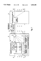
- FIG. 1 is a schematic block diagram of the Subject System illustrating the timed-round-robin transmission of data in both a synchronous and an asynchronous mode determined by a cell transmission scheduler adapted to permit data transmission in asynchronous time slots based on unused synchronous transmission time;
- FIGS. 2 and 3 are diagrams illustrating the format or protocol for the synchronous/asynchronous transmission of data over a transmission link, showing the ability to make use of unused synchronous time by augmenting the adjacent asynchronous time slot so that it can be used to transmit data, thereby to permit dynamic bandwidth sharing;
- FIG. 4 is a flowchart illustrating the cell transmission scheduler of FIG. 1 showing the realization of the timed-round-robin cell transmission;
- FIG. 5 is a block diagram illustrating the transmission of cells from one switch to the next switch in which conflicts are avoided by restricting the peak bandwidth that each connection can use;
- FIG. 6 is a block diagram illustrating a situation in which the dynamic bandwidth at the upstream switch can cause a conflict at the downstream switch which results in data loss due to buffer overload, also illustrating the utilization of feedback control coupled to the cell transmission scheduler of FIG. 1 which avoids the conflict through the disabling of the asynchronous transmission;
- FIG. 7 is a flowchart illustrating one embodiment for accomplishing asynchronous cell transmission in the system illustrated in FIG. 4, also describing the interruption of asynchronous transmission based on the feedback from a downstream switch;
- FIG. 8 is a simplified schematic diagram of the timed-round-robin cell transmission scheduling technique of FIG. 1 illustrating sequential sampling of the data in a series connection;
- FIG. 9 is a timing chart for synchronous and asynchronous transmission illustrating guaranteed transmission times for different connections and variable length asynchronous time slots such that both guaranteed and reliable transmission of data can be achieved efficiently through dynamic utilization of transmission capacity or bandwidth;
- FIG. 10 is a block diagram of upstream and downstream switches illustrating bandwidth allocation for the two connections of the upstream switch which can be handled by the bandwidth of the associated outgoing transmission link of the downstream switch;
- FIG. 11 is a block diagram of the switching network of FIG. 10 illustrating congestion in the downstream switch when the bandwidth associated with one connection of the upstream switch plus the bandwidth of a connection at the downstream switch exceeds the bandwidth of the associated outgoing transmission link of the downstream switch;
- FIG. 12 is a block diagram illustrating the feedback to an upstream switch of the buffer status of a buffer in a downstream switch to inhibit asynchronous data transmission until such time as there is sufficient buffer space in the downstream switch;
- FIG. 13 is a diagrammatic representation of buffer management protocol for the buffer for a downstream switch illustrating buffer space allocated to the associated upstream switch;
- FIG. 14 is a graph illustrating the setting of the F-bit in the algorithm which controls the transmission of asynchronous data, in which the F-bit is set in accordance with the count of asynchronous cells in the buffer of FIG. 13;
- FIG. 15 is a block diagram illustrating shared buffer memory and a control unit along with multiplexing and demultiplexing circuits within a switch;
- FIG. 16 is a diagram illustrating a linked-list queueing structure to organize cell queues for connections passing through a switch
- FIG. 17 is an expanded block diagram of the control unit of FIG. 15 illustrating an idle address pool, a connection lookup table coupled to a control circuit for specifying the address for incoming cells to be store in the shared buffer memory, for updating the reading address registers, and for implementing timed-round-robin cell transmission scheduling;
- FIG. 18 is a diagram illustrating an enhanced linked-list queueing structure to handle multicast cells, cells which are to be sent to multiple outgoing links.
- FIG. 19 is a diagram illustrating the implementation of the queueing structure of FIG. 18 in a shared buffer memory.
- an upstream switch 10 is coupled to a downstream switch 12.
- Switch 10 has a number of incoming links 14 and a number of outgoing links 16, with one of the outgoing links 18 coupled to switch 12 as an incoming link.
- Switch 12 has a number of outgoing links 20 to which data on link 18 may be selectively switched.
- Switch 12 incorporates a buffer 22 which is utilized to store incoming data and to route it to one or more outgoing links.
- a buffer 24 adapted to store incoming data from various incoming links through connections to cell queues 26, 28, and 30 accomplished by conventional switching.
- incoming links 14 are connected by switch 10 to outgoing link 16 through the utilization of a timed-round-robin scheduling system which sequentially accesses data from queues 26-30 in accordance with scheduling provided by cell transmission scheduler 32.
- Buffer 24 is organized in a format of one queue per connection.
- a connection is defined as a single path connecting two end users.
- each queue is provided with a guaranteed transmission time, GTT, associated with a given connection.
- GTT1 indicates by shaded area 34 that only a part of the time needed to transmit the cells of this connection is used. Thus there is an unused synchronous transmission time for Connection 1.
- Connection 2 requires additional time to transmit its data, with the time exceeding GTT2, the guaranteed transmission time for this connection.
- the additional data 38 associated with Connection 2 may be transmitted to switch 12 asynchronously.
- GTT1 synchronous time slot
- the timed-round-robin scheduling is under the control of the scheduler 32 via a Connection 54 to transmitter 56. It is obviously important to be able to sense an empty portion of a queue. For this purpose an empty queue detector 58 is used to detect when a queue is empty during transmission to permit switching to the asynchronous mode.
- the control of transmitter 56 depends upon the output of synchronous time monitor 60 which determines if the synchronous time is not used up is determined by the detection of all empty queue.
- one time frame or cycle 62 includes a number of synchronous time slots 64, 66, and 68, with the time slots being variable in length depending on the guaranteed transmission time for each connection.
- asynchronous time slots 70, 72, and 74 are variable length depending upon scheduling.
- asynchronous time slot 70 can be augmented as indicated by arrow 76 to permit data transmission in that portion of time slot 64 for which no data for Connection 1 exists.
- the algorithm utilized by scheduler 52 of FIG. 1 includes a block 80 indicating starting the cell transmission from the first connection.
- a cell of Connection i is transmitted using the guaranteed transmission time of the connection.
- a timer is utilized to detect the expiration of synchronous transmission time for Connection i. If the synchronous time is not up, block 86 checks to ascertain if there are other cells in the corresponding queue. If the queue is empty, asynchronous transmission of data is authorized as illustrated at 88. Note that asynchronous transmission is also authorized when the synchronous transmission time is up. The expiration of asynchronous time is determined by timer 90, at which point the process is moved to the synchronous transmission of the next connection.
- Connection 1 and Connection 2 to switch 10 have data each occupying one half of the link bandwidth.
- Data associated with Connections 1 and 2 are time multiplexed to link 94 such that Connection 1 data is outputted over outgoing link 96, whereas Connection 2 data is switched to outgoing link 98.
- a Connection 3 having data occupying a bandwidth equal to half of the link bandwidth is to be coupled to outgoing link 96.
- the link capacity of outgoing link 96 is not exceeded, i.e., B/2 from Connection 1 plus B/2 from Connection 3 equals B.
- Connection 2 uses one fourth the link bandwidth, this would ordinarily permit an increase in the bandwidth associated with Connection 1 to 3/4 of the link bandwidth.
- some of the data from Connection 1 must be buffered as illustrated at 100.
- the result of the buffering requirement is an F-bit transmission back to switch 10 as illustrated by dotted line 102 indicating buffer occupation.
- block 88 in FIG. 4 is implemented as follows: As illustrated by arrow 110, the F-bit from the downstream switch is checked at a decision block 112 which either allows transmission of a cell or the transmission of an idle cell which is equivalent to blocking the transmission of data to the downstream switch. If there is no enabling F-bit, then block 114 provides for the sending of this idle cell. If there is an enabling F-bit, then decision block 116 checks to see if there is data to be transmitted. If all queues are empty, then an idle cell is sent. If data exists in a queue, then as illustrated at 118, a data cell is sent.
- STM Synchronous Transfer Mode
- STM divides time into fixed length frames each of which is further divided into smaller time slots. Guaranteed bandwidth transmission is realized by allocating certain numbers of time slots in each frame to individual connections.
- STM has been quite successful in telecommunication networks, it is not suitable for the future integrated networks due to its inflexibility in bandwidth allocation and inefficiency in bandwidth utilization. Specifically, with STM, it is difficult to manage time slots to provide connections with different guaranteed bandwidths and allow connections to dynamically share transmission bandwidth.
- ATM uses a cell-based transmission approach which does not statically allocate time-slots to connections.
- Each cell is a self-contained unit which can be transmitted at any time.
- users can share transmission bandwidth efficiently and a high network utilization can be achieved.
- a consequence of this dynamic bandwidth sharing is that it becomes difficult to provide bandwidth guarantees to connections.
- Stop-and-Go divides time into frames. But instead of allocating fixed time-slots within each frame to connections, Stop-and-Go uses a stop-queue and a go-queue to limit the number of cells that each connection can transmit during each time frame. In this way, bandwidth can be flexibly managed. That is, connections with different bandwidths can be easily accommodated. But limiting the number of cells in each frame diminishes the ability of dynamic bandwidth sharing.
- Timed-Round-Robin scheduling can realize similar bandwidth allocation ability as Stop-and-Go, but it has the advantage of being easier to incorporate a feedback flow control scheme to achieve dynamic bandwidth sharing and lossless transmission by using a concept of synchronous and asynchronous transmissions.
- time is divided into fixed-size frames called a Round-Robin Period, RRP.
- RRP Round-Robin Period
- GTT Guaranteed Transmission Time
- GTT Guaranteed Transmission Time
- Any remaining time is used to transmit cells asynchronously subject to a feedback flow control scheme. In this way, one can simultaneously achieve guaranteed bandwidth allocation and dynamic bandwidth sharing.
- connections is used instead of virtual circuits, VCs, or virtual paths, VPs, as used in ATM standards to indicate that a connection can actually represent one or many VCs/VPs.
- the proposed timed-round-robin cell transmission algorithm is given below and illustrated in FIGS. 8 and 9:
- Algorithm 1 Timed-round-robin transmission.
- Each link is assigned a round-robin period, RRP, which is the time of completing one round of round-robin transmission, and a round-robin timer, RRT, which controls the time that each connection can use to transmit its cells.
- RRP round-robin period
- RRT round-robin timer
- GTT/RRP ⁇ link bandwidth is the bandwidth allocated to the connection over a link.
- Step 2 Transmit up to GTT i cells of CN i , or more specifically, transmit cells of CN i until RRT reaches T i or all cells of CN i have been transmitted. Cells transmitted in this way are marked as synchronous cells.
- Step 3 Transmit cells with an asynchronous transmission algorithm described in the next Section until RRT reaches T i + i ⁇ /n . Cells transmitted in this way are marked as asynchronous cells.
- FIGS. 8 and 9 show a queuing structure for round-robin transmission and a pattern of alternations between synchronous and asynchronous transmissions when each connection uses all its guaranteed transmission time transmitting synchronous cells. If a connection does not use all its assigned guaranteed transmission time, the remaining time is used for asynchronous transmission as indicated by the small arrows in the time chart.
- B i (GTT i /RRP) ⁇ B average bandwidth over the link.
- the first property is that the worst-case cell queuing delay at one node is bounded by RRP.
- the second property is that the maximum buffer needed for connection i is bounded by the GTT i .
- GTT/RRP ⁇ link bandwidth is the bandwidth guaranteed to a connection over a link.
- the connection can be accepted over a link if the summation of GTTs over all connections passing through the link does no exceed RRP.
- An addition or deletion of a connection needs to change the values of T i 's and ⁇ , which can be done at the end of a round-robin transmission period.
- connection establishment procedure due to the ceiling operation in calculating GTTs, a connection may be allocated slightly different bandwidths over links with different RRPs. If the bandwidth allocated to a connection over an upstream link is larger than that over a downstream link, cell losses might happen. Since a connection is usually established sequentially over links from its source to destination, this problem can be avoided by using the bandwidth actually allocated to a connection at an upstream link to calculate the GTT required at the next downstream link. In this way, lossless synchronous transmission is guaranteed.
- Algorithm 1 would behave very much like STM or Stop-and-Go if no asynchronous transmission were allowed in Step 3. Each connection is allocated a certain amount of bandwidth, but any unused or unallocated bandwidth is wasted. So the next step is to develop an asynchronous transmission algorithm to make efficient and safe use of the remaining bandwidth.
- efficient is meant that one should be able to transmit as many asynchronous cells as possible, and by “safe” is meant that one should not transmit too many cells as to overflow a downstream node and cause cell losses.
- FIGS. 10 and 11 show an example that an uncontrolled dynamic bandwidth sharing may cause buffer overflows.
- three connections, C1, C2, and C3, are each allocated one half of the link transmission bandwidth as shown in FIG. 10. No congestion will occur if each connection uses its own allocated bandwidth only.
- C2 uses only one half of its allocated bandwidth and the unused half is dynamically shared by C1, then cell losses may happen due to a congestion at a downstream node as shown in FIG. 11.
- dynamic bandwidth sharing i.e., asynchronous transmission in Algorithm 1, should be permitted only when there is enough buffer space at a downstream node.
- a simple link-by-link feedback flow control scheme is used to enable or disable asynchronous transmissions of a node.
- an F-bit in each cell flowing from a downstream node B to a current node A is used to control asynchronous transmissions of Node A, For simplicity, it is assumed that transmission bandwidths in both directions are the same.
- the F-bit is marked either as ENABLED or DISABLED.
- an appropriate F-bit setting algorithm can be used at Node B to ensure that there is no buffer overflow by disabling the asynchronous transmission of node A when otherwise it will cause a buffer overflow at node B, and there is no buffer underflow by enabling the asynchronous transmission of node A when it will not cause a buffer overflow at node B.
- a cell inserting scheme which transmits idle cells containing the feedback information only over otherwise idle transmission links.
- a buffer space of M cells is allocated at node B to store cells from node A as shown in FIG. 13, since synchronous transmission is not control by a feedback control scheme, according to Section 2, in the worst case a buffer of RRP cells is needed to store synchronous cells, resulting a buffer of M-RRP cells for asynchronous cells.
- R be the round-trip propagation delay from node B to node A.
- Algorithm 2 (F-bit setting algorithm 1).
- a counter C is used to record the number of asynchronous cells arrived from node A which are currently being buffered at node B.
- First is the problem of counting of asynchronous cells.
- cells belonging to one connection are transmitted in a FIFO, or First In First Out order.
- asynchronous cells arrived from Node A may be transmitted with synchronous transmission times, i.e., GTT i 's, at Node B.
- GTT i 's synchronous transmission times
- Algorithm 2 can not prevent buffer underflows. It is possible that node B has a free buffer of up to R cells, but no asynchronous transmission is allowed from node A. This may cause significant buffer and bandwidth wastes for networks with large inter-node propagation delays. In the worst-case where R>M-RRP, the asynchronous transmissions will be completely blocked.
- Algorithm 3 Management of counter C
- C is increased by 1 when an asynchronous cell arrives from Node A
- S i is increased by 1 when a synchronous cell of connection i arrives from Node A.
- Node B transmits a cell of connection i with the asynchronous transmission algorithm (i.e., Step 3 in Algorithm 1), then
- node B can safely send out M-RRP-C cells with F-bits set to ENABLED to node A which would allow node A to transmit up to this number of asynchronous cells.
- This approach can be realized with the following F-bit setting algorithm.
- Algorithm 4 (F-bit setting algorithm 2).
- a counter C is maintained using Algorithm 3.
- Algorithm 4 is still conservative since it is assumed that up to R extra asynchronous cells may arrive from Node A after t ed (i.e., when F is changed from ENABLED to DISABLED). This is not always true. For example, under certain conditions, only up to M-RRP-C de extra asynchronous cells may arrive after F is set to DISABLED in Step 6. So it is possible to develop a more efficient F-bit setting algorithm than Algorithm 4 at an extra implementation cost.
- Node B allows node A to do asynchronous transmission, what cells should Node A pick up to transmit? The answer to this question depends on the desired performance of asynchronous transmission. If fairness among connections is required, then a pure round-robin scheduling policy can be used. Also, priority or timed-round-robin scheduling can be used to distinguish importance between connections.
- Per-connection control means that each connection must maintain its own credit count which is updated using the information transmitted individually from a downstream node. Also, the buffer space is statically allocated to each connection. A consequence of this is the complexity of the credit management mechanism and the requirement for a large buffer to achieve dynamic bandwidth sharing.
- each connection is guaranteed a certain amount of minimum bandwidth and no connections will be blocked completed.
- a per-link feedback control scheme which treats all connections over a link as a single one. This significantly simplifies the feedback mechanism and reduces the buffer requirement.
- the second simplification involves state-based instead of credit-based feedback control.
- another simplification which has been made is the usage of just 1 bit in a feedback cell to indicate the current buffer occupation state at a downstream node, instead of the credit count value.
- This makes it possible to encode the feedback information in regular cells flowing from a downstream node to a current node and relieves a node from the burden of creating special feedback cells.
- letting regular cells carry feedback information enables realization of continuous feedback control by using a cell insertion scheme.
- a shared-buffer ATM switch is assumed as shown in FIG. 15.
- Incoming cells are multiplexed and stored in a Shared Buffer Memory 200 which are later demultiplexed to their corresponding outgoing links and transmitted to their next nodes.
- a Control Unit 202 provides idle addresses in the memory 200 to a multiplexor 204 to store incoming cells. Control Unit 202 also provides addresses of cells stored in the memory 200 to a demultiplexor 206 for cell transmissions.
- a key requirement to implement a round-robin cell transmission scheme is to maintain a FIFO cell queue for each connection.
- One way of doing this is to use a linked-list queueing structure as shown in FIG. 16.
- a tag 210 is added to a cell 212 stored in memory 200 which serves as a pointer to the location of the next cell 210' in a queue.
- the addresses of the first and last cells of queues are stored in a Connection Lookup Table 216 in Control Unit 202.
- the architecture of Control Unit 202 is shown in FIG. 17 which manages the cell queues and schedules cells to be transmitted in the following ways:
- an Idle Address Pool 200 is used to store idle addresses in the memory 200 where incoming cells can be stored.
- One address is allocated from pool 220 to each incoming cell as shown by path 1 in FIG. 17.
- path 1 When a cell is transmitted, its address in memory 200 is returned to pool 220 via path 2.
- a Reading Address Register 222 is used for each outgoing link which provides the address of the cell in memory 200 which should be transmitted next as illustrated by path 3.
- Registers 222 are updated by a Control Circuit 224 via path 4 according to the cell transmission scheduling algorithm used.
- Connection Lookup Table 224 is used to store information for each connection.
- the information useful for implementing the proposed traffic control scheme includes: addresses of the first and last cells of cell queues, allocated Guaranteed Transmission Times GTT i 's, synchronous cell counts S i 's, pointers to the next and last connections to realize a desired round-robin order, etc..
- Connection Lookup Table 226 can be constructed as an individual component, or more conveniently, be combined with the existing virtual-circuit routing tables in ATM switches.
- Idle Address is read from the pool 220 where the cell is to be stored. This Idle Address and the header of the incoming cell which contains the connection identification number are also forwarded to a Control Circuit 224 via paths 5 and 6. If the First Cell Address of the connection in Connection Lookup Table 226 is not set, i.e., the queue is empty, both the First Cell Address and Last Cell Address are set to be the Idle Address via path 7. Otherwise, only the Last Cell Address is set to be Idle Address and the original value of the last cell address is sent to MUX 204 so that the tag of the cell stored at the original last cell address can be updated to be the Idle Address via paths 7 and 5.
- the First Cell Address field should be updated to the address of the next cell in the queue. This is done by writing the tag of the cell transmitted into the the First Cell Address field via paths 8 and 7. To reduce the frequency that Connection Lookup Table 226 is accessed, this operation only needs to be performed at a connection switching time, i.e., when a transmitter stops transmitting cells of one connection and switches to another connection.
- Control Circuit 224 performs one of the following three actions to provide the address of Cell 1 , denoted by p 1 , to Reading Address Registers 222:
- the proposed traffic control scheme can be easily implemented in an exiting ATM switch architecture.
- one problem with the conventional linked-list structure is its inability to support multicast transmissions in a shared-buffer switch where one cell may appear in several queues.
- This problem is solved by using the enhanced linked-list data structure shown in FIG. 18 where a cell belonging to multiple queues uses multiple tags each pointing to the next cell of a queue.
- the enhanced linked-list would be able to handle multicast cells.
- Implementation of the enhance linked-list queueing structure in the memory 200 can be done in one of the following two ways:
- the first way is to enlarge the tag field.
- the second way is to use an indirect addressing scheme. Since not every cell is a multicast one, one can reduce the buffer overheads by making the tag field of a cell just large enough to hold one pointer, 2 bytes in the above example. For a unicast cell, its tag directly points to the next cell in a queue as shown in FIG. 16. For a multicast cell, this tag is served as an indirect pointer to a place where actual pointers are stored as shown in FIG. 19. This approach can reduce the average buffer overheads, but requires a faster shared buffer memory since it needs two buffer accesses to transmit a multicast cell.
- enhance linked-list structure is also useful for fault-tolerance since multiple tags can be used to serve as redundant pointers to the next cell in a queue.
Abstract
Description
Claims (8)
Priority Applications (2)
| Application Number | Priority Date | Filing Date | Title |
|---|---|---|---|
| US08/224,671 US5392280A (en) | 1994-04-07 | 1994-04-07 | Data transmission system and scheduling protocol for connection-oriented packet or cell switching networks |
| JP7107939A JPH0846590A (en) | 1994-04-07 | 1995-04-07 | Data transmission system |
Applications Claiming Priority (1)
| Application Number | Priority Date | Filing Date | Title |
|---|---|---|---|
| US08/224,671 US5392280A (en) | 1994-04-07 | 1994-04-07 | Data transmission system and scheduling protocol for connection-oriented packet or cell switching networks |
Publications (1)
| Publication Number | Publication Date |
|---|---|
| US5392280A true US5392280A (en) | 1995-02-21 |
Family
ID=22841661
Family Applications (1)
| Application Number | Title | Priority Date | Filing Date |
|---|---|---|---|
| US08/224,671 Expired - Lifetime US5392280A (en) | 1994-04-07 | 1994-04-07 | Data transmission system and scheduling protocol for connection-oriented packet or cell switching networks |
Country Status (2)
| Country | Link |
|---|---|
| US (1) | US5392280A (en) |
| JP (1) | JPH0846590A (en) |
Cited By (171)
| Publication number | Priority date | Publication date | Assignee | Title |
|---|---|---|---|---|
| US5495478A (en) * | 1994-11-14 | 1996-02-27 | Dsc Communications Corporation | Apparatus and method for processing asynchronous transfer mode cells |
| WO1996008115A1 (en) * | 1994-09-07 | 1996-03-14 | Philips Electronics N.V. | Mpeg information signal conversion system |
| US5521921A (en) * | 1994-03-15 | 1996-05-28 | Nec Corporation | Data communications method and apparatus |
| WO1996017453A2 (en) * | 1994-12-01 | 1996-06-06 | Philips Electronics N.V. | A communication system, a private automatic branch exchange, and a line card |
| US5528591A (en) * | 1995-01-31 | 1996-06-18 | Mitsubishi Electric Research Laboratories, Inc. | End-to-end credit-based flow control system in a digital communication network |
| US5528588A (en) * | 1994-09-14 | 1996-06-18 | Fore Systems, Inc. | Multicast shared memory |
| US5535201A (en) * | 1995-05-10 | 1996-07-09 | Mitsubishi Electric Research Laboratories, Inc. | Traffic shaping system using two dimensional timing chains |
| US5541926A (en) * | 1992-10-02 | 1996-07-30 | Kabushiki Kaisha Toshiba | ATM cell assembly and disassembly device with enhanced data handling flexibility |
| US5561663A (en) * | 1994-12-30 | 1996-10-01 | Stratacom, Inc. | Method and apparatus for performing communication rate control using geometric weighted groups |
| US5561669A (en) * | 1994-10-26 | 1996-10-01 | Cisco Systems, Inc. | Computer network switching system with expandable number of ports |
| US5561791A (en) * | 1995-04-10 | 1996-10-01 | Digital Equipment Corporation | Method and apparatus for conditioning timed program independent of transport timing |
| US5570348A (en) * | 1994-04-28 | 1996-10-29 | Integrated Telecom Technology, Inc. | Method and apparatus for enqueueing data cells in an ATM switch fabric architecture |
| US5570355A (en) * | 1994-11-17 | 1996-10-29 | Lucent Technologies Inc. | Method and apparatus enabling synchronous transfer mode and packet mode access for multiple services on a broadband communication network |
| US5579312A (en) * | 1994-06-28 | 1996-11-26 | Hewlett-Packard Company | Method and apparatus for scheduling the transmission of cells of guaranteed-bandwidth virtual channels |
| US5579302A (en) * | 1994-08-31 | 1996-11-26 | Hewlett-Packard Company | Method and apparatus for regulating virtual-channel cell transmission |
| WO1997004562A1 (en) * | 1995-07-19 | 1997-02-06 | Fujitsu Network Communications, Inc. | Point-to-multipoint arbitration |
| US5604742A (en) * | 1995-05-31 | 1997-02-18 | International Business Machines Corporation | Communications system and method for efficient management of bandwidth in a FDDI station |
| US5608733A (en) * | 1994-11-29 | 1997-03-04 | Valle; Richard | ATM inverse multiplexing |
| US5621898A (en) * | 1994-11-29 | 1997-04-15 | Compaq Computer Corporation | Arbiter organization for serial bus transfers |
| US5640392A (en) * | 1994-07-15 | 1997-06-17 | Sony Corporation | Signal receiving apparatus |
| EP0782301A1 (en) * | 1995-12-27 | 1997-07-02 | Digital Equipment Corporation | Method and apparatus for rate-based scheduling using a relative error approach |
| EP0798897A2 (en) * | 1996-03-26 | 1997-10-01 | Digital Equipment Corporation | Method and apparatus for relative error scheduling using discrete rates and proportional rate scaling |
| US5696764A (en) * | 1993-07-21 | 1997-12-09 | Fujitsu Limited | ATM exchange for monitoring congestion and allocating and transmitting bandwidth-guaranteed and non-bandwidth-guaranteed connection calls |
| AU685701B2 (en) * | 1995-04-10 | 1998-01-22 | Digital Equipment Corporation | Method and apparatus for conditioning and transporting timed program data, independent of transport timing |
| US5745487A (en) * | 1995-11-16 | 1998-04-28 | Matsushita Electric Industrial Co., Ltd. | Communication apparatus for transmitting/receiving different types of data in one TDM slot |
| US5748905A (en) | 1996-08-30 | 1998-05-05 | Fujitsu Network Communications, Inc. | Frame classification using classification keys |
| US5748614A (en) * | 1995-06-09 | 1998-05-05 | Siemens Aktiengesellschaft | Method for scheduling message cells leaving an ATM node |
| US5781533A (en) | 1995-07-19 | 1998-07-14 | Fujitsu Network Communications, Inc. | Link buffer sharing method and apparatus |
| US5790534A (en) * | 1996-09-20 | 1998-08-04 | Nokia Mobile Phones Limited | Load control method and apparatus for CDMA cellular system having circuit and packet switched terminals |
| US5802049A (en) * | 1995-08-14 | 1998-09-01 | Fujitsu Limited | Method of selecting route in cell switch |
| US5825748A (en) * | 1997-04-08 | 1998-10-20 | International Business Machines Corporation | Credit-based flow control checking and correction system |
| US5862127A (en) * | 1994-03-18 | 1999-01-19 | Electronics And Telecommunications Research Institute | Method of controlling the peak cell rate spacing of multiplexed ATM traffic |
| WO1999009689A1 (en) * | 1997-08-14 | 1999-02-25 | Motorola Inc. | System, device, and method for scheduling in a communication network |
| US5881061A (en) * | 1995-06-07 | 1999-03-09 | Nippon Telegraph And Telephone Corporation | Method and system for data communication |
| US5886980A (en) * | 1996-08-23 | 1999-03-23 | Mitsubishi Electric Information Technology Center America, Inc. | Bit stream based connection admission control system |
| US5898671A (en) | 1995-09-14 | 1999-04-27 | Fujitsu Network Communications, Inc. | Transmitter controlled flow control for buffer allocation in wide area ATM networks |
| WO1999026446A2 (en) * | 1997-11-18 | 1999-05-27 | Cabletron Systems, Inc. | Non-zero minimum cell rate for available bit rate atm service |
| WO1999026422A2 (en) * | 1997-11-14 | 1999-05-27 | Shiron Satellite Communications (1996) Ltd. | Reverse link for a satellite communication network |
| US5953336A (en) * | 1996-08-05 | 1999-09-14 | Virata Limited | Method and apparatus for source rate pacing in an ATM network |
| WO1999048257A1 (en) * | 1998-03-18 | 1999-09-23 | Conexant Systems, Inc. | Apparatus and method for scheduling multiple and simultaneous connections in a communication system |
| US5960215A (en) * | 1996-09-12 | 1999-09-28 | Digital Equipment Corporation | Transmit data FIFO for flow controlled data |
| US5991298A (en) | 1996-01-16 | 1999-11-23 | Fujitsu Network Communications, Inc. | Reliable and flexible multicast mechanism for ATM networks |
| US5995487A (en) * | 1997-08-06 | 1999-11-30 | Northern Telecom Limited | Method and apparatus for providing subscribers with unguaranteed bandwidth connections wherein subscribers are alerted by encoded messages or a warning tone |
| WO1999062233A1 (en) * | 1998-05-29 | 1999-12-02 | Conexant Systems, Inc. | Apparatus and method for providing simultaneous and multiple quality of service connections in a tunnel mode |
| WO1999065179A2 (en) * | 1998-06-08 | 1999-12-16 | Jetstream Communications, Inc. | System and method for communicating voice and data over a local packet network |
| US6021114A (en) * | 1997-04-18 | 2000-02-01 | Siemens Information And Communication Networks, Inc. | Method and system for utilizing communications lines |
| US6044406A (en) * | 1997-04-08 | 2000-03-28 | International Business Machines Corporation | Credit-based flow control checking and correction method |
| US6047000A (en) * | 1997-07-24 | 2000-04-04 | The Hong Kong University Of Science & Technology | Packet scheduling system |
| US6052386A (en) * | 1995-09-12 | 2000-04-18 | U.S. Philips Corporation | Transmission system for synchronous and asynchronous data portions |
| US6055242A (en) * | 1996-03-20 | 2000-04-25 | Lucent Technologies Inc. | Method and apparatus enabling synchronous transfer mode, variable length and packet mode access for multiple services over a broadband communication network |
| US6108346A (en) * | 1998-08-27 | 2000-08-22 | Xiox Corporation | Combined synchronous and asynchronous message transmission |
| US6111888A (en) * | 1997-05-27 | 2000-08-29 | Micro Motion, Inc. | Deterministic serial bus communication system |
| US6111858A (en) * | 1997-02-18 | 2000-08-29 | Virata Limited | Proxy-controlled ATM subnetwork |
| US6122251A (en) * | 1996-11-13 | 2000-09-19 | Nec Corporation | Switch control circuit and control method of ATM switchboard |
| US6175566B1 (en) * | 1996-09-11 | 2001-01-16 | Electronics And Telecommunications Research Institute | Broadcast transfer method for a hierarchical interconnection network with multiple tags |
| US6181947B1 (en) * | 1997-02-28 | 2001-01-30 | U.S. Philips Corporation | System for the wireless transmission of a frame-synchronized signal between a radio base station and at least one mobile terminal |
| US6195333B1 (en) * | 1996-10-28 | 2001-02-27 | Fujitsu Network Communications, Inc. | Unframed isochronous shaping method to reduce delay and delay variation in a CBR transmission system |
| US6198724B1 (en) | 1997-10-02 | 2001-03-06 | Vertex Networks, Inc. | ATM cell scheduling method and apparatus |
| US6212181B1 (en) * | 1999-03-26 | 2001-04-03 | Cisco Technology, Inc. | Method for using the departure queue memory bandwidth to support additional cell arrivals in an ATM switch |
| US6212182B1 (en) * | 1996-06-27 | 2001-04-03 | Cisco Technology, Inc. | Combined unicast and multicast scheduling |
| EP1090482A1 (en) * | 1998-06-19 | 2001-04-11 | Ascend Communications, Inc. | Logical multicasting method and apparatus |
| US20010002473A1 (en) * | 1998-02-26 | 2001-05-31 | Sun Microsystems, Inc. | Dynamic lookup service in a distributed system |
| US6246687B1 (en) * | 1997-03-27 | 2001-06-12 | Massachusetts Institute Of Technology | Network switching system supporting guaranteed data rates |
| US6249819B1 (en) | 1996-12-06 | 2001-06-19 | Fujitsu Network Communications, Inc. | Method for flow controlling ATM traffic |
| US6272109B1 (en) | 1997-11-18 | 2001-08-07 | Cabletron Systems, Inc. | Hierarchical schedules for different ATM traffic |
| US6285657B1 (en) * | 1999-09-28 | 2001-09-04 | Conexant Systems, Inc. | System and method of scheduling data cells based upon sustainable cell rate and peak cell rate over a variable bandwidth channel |
| US6308246B1 (en) | 1997-09-05 | 2001-10-23 | Sun Microsystems, Inc. | Skewed finite hashing function |
| WO2001080504A1 (en) * | 2000-04-10 | 2001-10-25 | Appian Communications, Inc. | Packet switch including usage monitor and scheduler |
| US6310891B1 (en) * | 1997-12-18 | 2001-10-30 | Alcatel Usa Sourcing, L.P. | Method of scheduling time division multiplex (TDM) cells in a synchronous optical network (SONET) frame |
| USRE37435E1 (en) | 1990-10-19 | 2001-11-06 | Fujitsu Limited | Supervision control system |
| US6320861B1 (en) * | 1998-05-15 | 2001-11-20 | Marconi Communications, Inc. | Hybrid scheme for queuing in a shared memory ATM switch buffer |
| US6324184B1 (en) * | 1996-03-18 | 2001-11-27 | General Instrument Corporation | Dynamic bandwidth allocation for a communication network |
| US20010046208A1 (en) * | 2000-05-05 | 2001-11-29 | Eng Kai Y. | Unbreakable optical IP flows and premium IP services |
| US20010049713A1 (en) * | 1998-02-26 | 2001-12-06 | Sun Microsystems Inc. | Method and apparatus for dynamic distributed computing over a network |
| US20020021678A1 (en) * | 2000-07-06 | 2002-02-21 | Antony Heatwole | Apportioning bandwidth capacity in communication switching systems |
| WO2002017552A1 (en) * | 2000-08-24 | 2002-02-28 | Ocular Networks | Apparatus and method for facilitating data packet transportation |
| US6377579B1 (en) * | 1998-06-11 | 2002-04-23 | Synchrodyne Networks, Inc. | Interconnecting a synchronous switching network that utilizes a common time reference with an asynchronous switching network |
| US6389540B1 (en) | 1998-02-26 | 2002-05-14 | Sun Microsystems, Inc. | Stack based access control using code and executor identifiers |
| US20020057680A1 (en) * | 1998-07-22 | 2002-05-16 | Yoram Ofek | Switching methods with common time reference and plurality of time frame durations |
| US6396853B1 (en) * | 1998-05-28 | 2002-05-28 | Nortel Networks Limited | Providing data services to telecommunications user terminals |
| US6408005B1 (en) * | 1997-09-05 | 2002-06-18 | Nec Usa, Inc. | Dynamic rate control scheduler for ATM networks |
| US6438614B2 (en) * | 1998-02-26 | 2002-08-20 | Sun Microsystems, Inc. | Polymorphic token based control |
| US20020124118A1 (en) * | 2001-01-04 | 2002-09-05 | Colley Adrian E. | Method and system for passing objects in a distributed system using serializatin contexts |
| US6449648B1 (en) | 1996-10-11 | 2002-09-10 | Sun Microsystems, Inc. | Lease renewal service |
| US6449252B1 (en) * | 1999-06-18 | 2002-09-10 | Cisco Technology, Inc. | ATM path cell scheduling for constant and variable bit rate traffic |
| US6459681B1 (en) * | 1998-11-13 | 2002-10-01 | Sprint Communications Company L.P. | Method and system for connection admission control |
| US6466586B1 (en) * | 1998-03-31 | 2002-10-15 | Nortel Networks Limited | Digital subscriber line framing structure supporting imbedded rate adaptive synchronous and asynchronous traffic |
| US6466947B2 (en) | 1998-03-20 | 2002-10-15 | Sun Microsystems, Inc. | Apparatus and method for dynamically verifying information in a distributed system |
| US6466587B1 (en) | 1998-02-23 | 2002-10-15 | Sony Corporation | Wireless transmitting method |
| US6480863B1 (en) | 1997-11-17 | 2002-11-12 | Sun Microsystems, Inc. | Method and system for multi-entry and multi-template matching in a database |
| US6487607B1 (en) | 1998-02-26 | 2002-11-26 | Sun Microsystems, Inc. | Methods and apparatus for remote method invocation |
| US20020181475A1 (en) * | 2001-06-04 | 2002-12-05 | Jason Dove | Traffic merging system |
| US20020199036A1 (en) * | 1998-03-20 | 2002-12-26 | Sun Microsystems, Inc. | Downloadable smart proxies for performing processing associated with a remote procedure call in a distributed system |
| US20030002517A1 (en) * | 2001-06-28 | 2003-01-02 | Ryo Takajitsuko | Communications apparatus and communications control method |
| US20030007502A1 (en) * | 2001-06-04 | 2003-01-09 | Jason Dove | Concurrent switching of synchronous and asynchronous traffic |
| US6510165B1 (en) * | 1995-09-06 | 2003-01-21 | Fujitsu Limited | Band controlling apparatus |
| US6519615B1 (en) | 1996-10-11 | 2003-02-11 | Sun Microsystems, Inc. | Method and system for leasing storage |
| US20030051029A1 (en) * | 2001-09-07 | 2003-03-13 | Reedy Dennis G. | Dynamic provisioning of sevice components in a distributed system |
| FR2829648A1 (en) * | 2001-09-13 | 2003-03-14 | 6Wind | Different communication interface ordering technique processing packet input/reallocating pass band/ordering queue and allocation class guaranteeing minimal pass band following priority level/excess band reallocated optimizing traffic |
| US6535503B1 (en) * | 1996-10-15 | 2003-03-18 | Nokia Telecommunications | Channel allocation method and radio system using a combination of TDMA and CDMA |
| KR100378333B1 (en) * | 1995-04-28 | 2003-03-29 | 마쯔시다덴기산교 가부시키가이샤 | Data transmitter, data receiver, and data transmission controller |
| US6549537B2 (en) * | 1997-05-15 | 2003-04-15 | Sony Corporation | Communication system and method |
| EP1303162A2 (en) * | 2001-10-09 | 2003-04-16 | Alcatel Canada Inc. | Apparatus and method for dynamic bandwidth allocation with minimum bandwidth guarantee |
| US6560656B1 (en) | 1998-02-26 | 2003-05-06 | Sun Microsystems, Inc. | Apparatus and method for providing downloadable code for use in communicating with a device in a distributed system |
| US6564240B2 (en) | 1996-10-11 | 2003-05-13 | Sun Microsystems, Inc. | Method, apparatus, and product for leasing of group membership in a distributed system |
| US6598086B1 (en) * | 1999-11-09 | 2003-07-22 | International Business Machines Corporation | Method and system for controlling information flow in a high frequency digital system from a producer to a buffering consumer via an intermediate buffer |
| US6598094B1 (en) | 1998-03-20 | 2003-07-22 | Sun Microsystems, Inc. | Method and apparatus for determining status of remote objects in a distributed system |
| US6597668B1 (en) * | 1996-11-07 | 2003-07-22 | Harris Broadband Wireless Access, Inc. | System and method for maximizing efficiency in a time division duplex system employing dynamic asymmetry |
| US6601105B1 (en) | 1999-11-09 | 2003-07-29 | International Business Machines Corporation | Method and system for controlling information flow between a producer and multiple buffers in a high frequency digital system |
| US6604145B1 (en) * | 1999-11-09 | 2003-08-05 | International Business Machines Corporation | Method and system for controlling information flow in a high frequency digital system from a producer to a buffering consumer via an intermediate buffer and a shared data path |
| US6604127B2 (en) | 1998-03-20 | 2003-08-05 | Brian T. Murphy | Dynamic lookup service in distributed system |
| US6606666B1 (en) | 1999-11-09 | 2003-08-12 | International Business Machines Corporation | Method and system for controlling information flow between a producer and a buffer in a high frequency digital system |
| US6629154B1 (en) | 1998-02-26 | 2003-09-30 | Sun Microsystems, Inc. | Method and system for deterministic hashes to identify remote methods |
| US20030191842A1 (en) * | 1998-02-26 | 2003-10-09 | Sun Microsystems Inc. | Dynamic lookup service in a distributed system |
| US6643290B1 (en) | 1998-01-30 | 2003-11-04 | Siemens Aktiengesellschaft | Method for controlling accesses to resources of a communication network |
| US6651119B2 (en) * | 1998-11-16 | 2003-11-18 | Lsi Logic Corporation | Method for allocating priorities to plurality of DMA engines for processing data packets based on bus phase and transactions status |
| US6654793B1 (en) | 1996-04-23 | 2003-11-25 | Sun Microsystems, Inc. | System and method for facilitating dynamic loading of stub information to enable a program operating in one address space to invoke processing of a remote method or procedure in another address space |
| US6678282B2 (en) * | 1996-10-23 | 2004-01-13 | Cisco Technology, Inc. | System and method for communicating packetized data over a channel bank |
| US20040030777A1 (en) * | 2001-09-07 | 2004-02-12 | Reedy Dennis G. | Systems and methods for providing dynamic quality of service for a distributed system |
| US6693895B1 (en) * | 1998-07-14 | 2004-02-17 | International Business Machines Corporation | Multiple synchronous data stream format for an optical data link |
| US20040038684A1 (en) * | 2002-07-01 | 2004-02-26 | Shigeru Sugaya | Wireless communication system, wireless communication device and method, and computer program |
| US6708171B1 (en) | 1996-04-23 | 2004-03-16 | Sun Microsystems, Inc. | Network proxy |
| US6721323B1 (en) | 1999-06-14 | 2004-04-13 | Tellab Operations, Inc. | Distributed virtual path |
| US6728737B2 (en) | 1996-10-11 | 2004-04-27 | Sun Microsystems, Inc. | Method and system for leasing storage |
| US6754240B1 (en) * | 1998-07-14 | 2004-06-22 | International Business Machines Corporation | Format for an optical data link |
| US6765871B1 (en) * | 2000-11-29 | 2004-07-20 | Akara Corporation | Fiber channel flow control method and apparatus for interface to metro area transport link |
| US6768736B1 (en) | 1998-12-30 | 2004-07-27 | Nortel Networks Limited | Using an ATM switch to grow the capacity of a switching stage |
| US6778538B2 (en) * | 1998-12-30 | 2004-08-17 | Nortel Networks Limited | Virtual junctors |
| US6781956B1 (en) | 1999-09-17 | 2004-08-24 | Cisco Technology, Inc. | System and method for prioritizing packetized data from a distributed control environment for transmission through a high bandwidth link |
| US6788703B2 (en) | 1998-12-30 | 2004-09-07 | Nortel Networks Limited | DS0 on ATM, mapping and handling |
| US6791991B1 (en) * | 2000-10-31 | 2004-09-14 | Agere Systems Inc. | Channel sequencing using a round-robin scheduler |
| US6804229B2 (en) | 1998-12-30 | 2004-10-12 | Nortel Networks Limited | Multiple node network architecture |
| US20040230643A1 (en) * | 1996-08-20 | 2004-11-18 | Invensys Systems, Inc. | Methods and apparatus for remote process control |
| US20040246977A1 (en) * | 2001-06-04 | 2004-12-09 | Jason Dove | Backplane bus |
| US6832223B1 (en) | 1996-04-23 | 2004-12-14 | Sun Microsystems, Inc. | Method and system for facilitating access to a lookup service |
| US6832265B1 (en) * | 2000-01-07 | 2004-12-14 | Cisco Technology, Inc. | Methods and apparatus for moving data elements within a data communications device |
| US6845393B1 (en) | 1999-06-14 | 2005-01-18 | Sun Microsystems, Inc. | Lookup discovery service in a distributed system having a plurality of lookup services each with associated characteristics and services |
| US20050036495A1 (en) * | 2003-08-12 | 2005-02-17 | John Wishneusky | Method and apparatus for scheduling packets |
| US20050068974A1 (en) * | 2003-09-25 | 2005-03-31 | International Business Machines Corporation | Shared transmit buffer for network processor and methods for using same |
| US6885661B1 (en) | 1998-12-30 | 2005-04-26 | Nortel Networks Limited | Private branch exchange built using an ATM Network |
| US6901518B1 (en) | 1999-04-08 | 2005-05-31 | Sun Microsystems, Inc. | Method and system for establishing trust in downloaded proxy code |
| US20050141451A1 (en) * | 2003-12-30 | 2005-06-30 | Samsung Electronics Co., Ltd. | Channel time allocation method in WPAN |
| US6931029B1 (en) * | 2000-02-09 | 2005-08-16 | Nortel Networks Limited | System and method for synchronizing with data received over an unreliable asynchronous medium |
| US6957427B1 (en) | 1997-10-15 | 2005-10-18 | Sun Microsystems, Inc. | Remote object activation in a distributed system |
| US7016356B1 (en) * | 2000-06-02 | 2006-03-21 | Italtel Spa | Method and system to assign transmission bandwidth in both radio and PON ATM P-MP systems |
| US20060083271A1 (en) * | 2004-10-19 | 2006-04-20 | Samsung Electronics Co.; Ltd | Apparatus for transmitting frame and method for controlling transmission of frame for strict synchronization |
| US20060206860A1 (en) * | 1999-05-17 | 2006-09-14 | Invensys Systems, Inc. | Process control configuration system with connection validation and configuration |
| US20060206866A1 (en) * | 1999-05-17 | 2006-09-14 | Invensys Systems, Inc. | Methods and apparatus for control configuration using live data |
| US20060271704A1 (en) * | 2000-04-16 | 2006-11-30 | Wai-Chung Chan | Approach to minimize worst-case queueing delay for a switching communication system with transmission constraints |
| US20060294579A1 (en) * | 2004-03-01 | 2006-12-28 | Invensys Systems, Inc. | Process control methods and apparatus for intrusion detection, protection and network hardening |
| US20070006235A1 (en) * | 2005-06-30 | 2007-01-04 | Intel Corporation | Task scheduling to devices with same connection address |
| US20070230501A1 (en) * | 2006-03-29 | 2007-10-04 | Honeywell International, Inc. | System and method for supporting synchronous system communications and operations |
| US20070233664A1 (en) * | 2006-03-30 | 2007-10-04 | Invensys Systems, Inc. | Digital data processing apparatus and methods for improving plant performance |
| US20080052386A1 (en) * | 1999-06-11 | 2008-02-28 | Invensys Systems, Inc. | Methods and apparatus for control using control devices that provide a virtual machine environment and that communicate via an ip network |
| US20080107221A1 (en) * | 2006-11-07 | 2008-05-08 | Shigeyuki Yamanaka | Communication apparatus and recording medium |
| US20080120424A1 (en) * | 2006-11-16 | 2008-05-22 | Deshpande Sachin G | Content-aware adaptive packet transmission |
| US20080259799A1 (en) * | 2007-04-20 | 2008-10-23 | Van Beek Petrus J L | Packet Scheduling with Quality-Aware Frame Dropping for Video Streaming |
| US20080273533A1 (en) * | 2007-05-02 | 2008-11-06 | Sachin Govind Deshpande | Adaptive Packet Transmission with Explicit Deadline Adjustment |
| US20090019155A1 (en) * | 2007-07-11 | 2009-01-15 | Verizon Services Organization Inc. | Token-based crediting of network usage |
| US20090046734A1 (en) * | 1995-12-29 | 2009-02-19 | Cisco Technology, Inc. | Method for Traffic Management, Traffic Prioritization, Access Control, and Packet Forwarding in a Datagram Computer Network |
| US20090247076A1 (en) * | 2006-07-21 | 2009-10-01 | Allan Bartlett | Radio frequency signal distribution using data cable system |
| US20100020698A1 (en) * | 2008-07-23 | 2010-01-28 | Fujitsu Limited | Communication apparatus and OAM frame transmission method |
| US7756969B1 (en) | 2001-09-07 | 2010-07-13 | Oracle America, Inc. | Dynamic provisioning of identification services in a distributed system |
| US7792874B1 (en) | 2004-01-30 | 2010-09-07 | Oracle America, Inc. | Dynamic provisioning for filtering and consolidating events |
| US20100305720A1 (en) * | 2009-05-29 | 2010-12-02 | Invensys Systems, Inc. | Methods and apparatus for control configuration with control objects that are fieldbus protocol-aware |
| CN1889561B (en) * | 2005-06-28 | 2010-12-08 | 中国人民解放军信息工程大学 | Synchronous and asynchronous MAC protocol smooth transient method in distributing network |
| US7911953B1 (en) * | 2005-11-16 | 2011-03-22 | Juniper Networks, Inc. | Multilink traffic shaping |
| US20110093098A1 (en) * | 2009-05-29 | 2011-04-21 | Invensys Systems, Inc. | Methods and apparatus for control configuration with enhanced change-tracking |
| US7945816B1 (en) * | 2005-11-30 | 2011-05-17 | At&T Intellectual Property Ii, L.P. | Comprehensive end-to-end storage area network (SAN) application transport service |
| US20120218984A1 (en) * | 2002-02-05 | 2012-08-30 | Sony Corporation | Wireless communication system and wireless communication control method, wireless communication device and wireless communication method, and computer program |
| US8594814B2 (en) | 2008-06-20 | 2013-11-26 | Invensys Systems, Inc. | Systems and methods for immersive interaction with actual and/or simulated facilities for process, environmental and industrial control |
Families Citing this family (8)
| Publication number | Priority date | Publication date | Assignee | Title |
|---|---|---|---|---|
| JP3552471B2 (en) * | 1996-07-29 | 2004-08-11 | ソニー株式会社 | Data recording / reproducing apparatus and method |
| JP2000092525A (en) * | 1998-09-16 | 2000-03-31 | Nec Corp | Cross connection system |
| JP2000262749A (en) * | 1999-03-18 | 2000-09-26 | Snk Corp | Communication device for game and game device |
| US6600756B1 (en) * | 1999-06-14 | 2003-07-29 | Hewlett-Packard Development Company, Lp. | Method of improving the performance of a bus which is asynchronous-traffic intensive |
| US6636500B2 (en) * | 1999-07-27 | 2003-10-21 | Lucent Technologies Inc. | Medium allocation method |
| DE602004019327D1 (en) * | 2004-02-18 | 2009-03-19 | Harman Becker Automotive Sys | ATAPI switch |
| KR100575989B1 (en) * | 2004-04-08 | 2006-05-02 | 삼성전자주식회사 | Segmentation Transmitting Method of Asynchronous Data In Synchronous Ethernet and Data Structure Used In Segmentation Transmitting Method |
| CN115280691A (en) * | 2020-03-06 | 2022-11-01 | 三菱电机株式会社 | Time division multiplex communication system, time division multiplex communication method, and program |
Citations (4)
| Publication number | Priority date | Publication date | Assignee | Title |
|---|---|---|---|---|
| US4587650A (en) * | 1984-10-30 | 1986-05-06 | Burroughs Corporation | Method of simultaneously transmitting isochronous and nonisochronous data on a local area network |
| US4637014A (en) * | 1984-02-17 | 1987-01-13 | Burroughs Corporation | Method of inserting and removing isochronous data into a sequence of nonisochronous data characters without slot allocation on a computer network |
| US4763321A (en) * | 1985-08-13 | 1988-08-09 | International Business Machines Corporation | Dynamic bandwidth allocation mechanism between circuit slots and packet bit stream in a communication network |
| US4914650A (en) * | 1988-12-06 | 1990-04-03 | American Telephone And Telegraph Company | Bandwidth allocation and congestion control scheme for an integrated voice and data network |
-
1994
- 1994-04-07 US US08/224,671 patent/US5392280A/en not_active Expired - Lifetime
-
1995
- 1995-04-07 JP JP7107939A patent/JPH0846590A/en active Pending
Patent Citations (4)
| Publication number | Priority date | Publication date | Assignee | Title |
|---|---|---|---|---|
| US4637014A (en) * | 1984-02-17 | 1987-01-13 | Burroughs Corporation | Method of inserting and removing isochronous data into a sequence of nonisochronous data characters without slot allocation on a computer network |
| US4587650A (en) * | 1984-10-30 | 1986-05-06 | Burroughs Corporation | Method of simultaneously transmitting isochronous and nonisochronous data on a local area network |
| US4763321A (en) * | 1985-08-13 | 1988-08-09 | International Business Machines Corporation | Dynamic bandwidth allocation mechanism between circuit slots and packet bit stream in a communication network |
| US4914650A (en) * | 1988-12-06 | 1990-04-03 | American Telephone And Telegraph Company | Bandwidth allocation and congestion control scheme for an integrated voice and data network |
Cited By (312)
| Publication number | Priority date | Publication date | Assignee | Title |
|---|---|---|---|---|
| USRE37435E1 (en) | 1990-10-19 | 2001-11-06 | Fujitsu Limited | Supervision control system |
| US5541926A (en) * | 1992-10-02 | 1996-07-30 | Kabushiki Kaisha Toshiba | ATM cell assembly and disassembly device with enhanced data handling flexibility |
| US5696764A (en) * | 1993-07-21 | 1997-12-09 | Fujitsu Limited | ATM exchange for monitoring congestion and allocating and transmitting bandwidth-guaranteed and non-bandwidth-guaranteed connection calls |
| US5521921A (en) * | 1994-03-15 | 1996-05-28 | Nec Corporation | Data communications method and apparatus |
| US5862127A (en) * | 1994-03-18 | 1999-01-19 | Electronics And Telecommunications Research Institute | Method of controlling the peak cell rate spacing of multiplexed ATM traffic |
| US5570348A (en) * | 1994-04-28 | 1996-10-29 | Integrated Telecom Technology, Inc. | Method and apparatus for enqueueing data cells in an ATM switch fabric architecture |
| US5579312A (en) * | 1994-06-28 | 1996-11-26 | Hewlett-Packard Company | Method and apparatus for scheduling the transmission of cells of guaranteed-bandwidth virtual channels |
| US5640392A (en) * | 1994-07-15 | 1997-06-17 | Sony Corporation | Signal receiving apparatus |
| US5579302A (en) * | 1994-08-31 | 1996-11-26 | Hewlett-Packard Company | Method and apparatus for regulating virtual-channel cell transmission |
| WO1996008115A1 (en) * | 1994-09-07 | 1996-03-14 | Philips Electronics N.V. | Mpeg information signal conversion system |
| US5528588A (en) * | 1994-09-14 | 1996-06-18 | Fore Systems, Inc. | Multicast shared memory |
| US5875189A (en) * | 1994-09-14 | 1999-02-23 | Fore Systems, Inc. | Method and apparatus for multicast of ATM cells |
| US5561669A (en) * | 1994-10-26 | 1996-10-01 | Cisco Systems, Inc. | Computer network switching system with expandable number of ports |
| US5495478A (en) * | 1994-11-14 | 1996-02-27 | Dsc Communications Corporation | Apparatus and method for processing asynchronous transfer mode cells |
| US5570355A (en) * | 1994-11-17 | 1996-10-29 | Lucent Technologies Inc. | Method and apparatus enabling synchronous transfer mode and packet mode access for multiple services on a broadband communication network |
| US5621898A (en) * | 1994-11-29 | 1997-04-15 | Compaq Computer Corporation | Arbiter organization for serial bus transfers |
| US5608733A (en) * | 1994-11-29 | 1997-03-04 | Valle; Richard | ATM inverse multiplexing |
| WO1996017453A3 (en) * | 1994-12-01 | 1996-08-08 | Philips Electronics Nv | A communication system, a private automatic branch exchange, and a line card |
| US5812548A (en) * | 1994-12-01 | 1998-09-22 | U.S. Philips Corporation | Communication system, a private automatic branch exchange, and a line card |
| WO1996017453A2 (en) * | 1994-12-01 | 1996-06-06 | Philips Electronics N.V. | A communication system, a private automatic branch exchange, and a line card |
| US5561663A (en) * | 1994-12-30 | 1996-10-01 | Stratacom, Inc. | Method and apparatus for performing communication rate control using geometric weighted groups |
| US5528591A (en) * | 1995-01-31 | 1996-06-18 | Mitsubishi Electric Research Laboratories, Inc. | End-to-end credit-based flow control system in a digital communication network |
| AU685701B2 (en) * | 1995-04-10 | 1998-01-22 | Digital Equipment Corporation | Method and apparatus for conditioning and transporting timed program data, independent of transport timing |
| US5561791A (en) * | 1995-04-10 | 1996-10-01 | Digital Equipment Corporation | Method and apparatus for conditioning timed program independent of transport timing |
| KR100378333B1 (en) * | 1995-04-28 | 2003-03-29 | 마쯔시다덴기산교 가부시키가이샤 | Data transmitter, data receiver, and data transmission controller |
| KR100392545B1 (en) * | 1995-04-28 | 2003-07-28 | 마쯔시다덴기산교 가부시키가이샤 | Data transmitter, data receiver, and data transmission controller |
| US5535201A (en) * | 1995-05-10 | 1996-07-09 | Mitsubishi Electric Research Laboratories, Inc. | Traffic shaping system using two dimensional timing chains |
| US5604742A (en) * | 1995-05-31 | 1997-02-18 | International Business Machines Corporation | Communications system and method for efficient management of bandwidth in a FDDI station |
| US5881061A (en) * | 1995-06-07 | 1999-03-09 | Nippon Telegraph And Telephone Corporation | Method and system for data communication |
| US5748614A (en) * | 1995-06-09 | 1998-05-05 | Siemens Aktiengesellschaft | Method for scheduling message cells leaving an ATM node |
| US5850395A (en) | 1995-07-19 | 1998-12-15 | Fujitsu Network Communications, Inc. | Asynchronous transfer mode based service consolidation switch |
| US5909427A (en) | 1995-07-19 | 1999-06-01 | Fujitsu Network Communications, Inc. | Redundant switch system and method of operation |
| US5790770A (en) | 1995-07-19 | 1998-08-04 | Fujitsu Network Communications, Inc. | Method and apparatus for reducing information loss in a communications network |
| US5822540A (en) | 1995-07-19 | 1998-10-13 | Fujitsu Network Communications, Inc. | Method and apparatus for discarding frames in a communications device |
| WO1997004562A1 (en) * | 1995-07-19 | 1997-02-06 | Fujitsu Network Communications, Inc. | Point-to-multipoint arbitration |
| US6002667A (en) | 1995-07-19 | 1999-12-14 | Fujitsu Network Communications, Inc. | Minimum guaranteed cell rate method and apparatus |
| US5862137A (en) | 1995-07-19 | 1999-01-19 | Fujitsu Network Communications, Inc. | Point-to-multipoint arbitration |
| US5781533A (en) | 1995-07-19 | 1998-07-14 | Fujitsu Network Communications, Inc. | Link buffer sharing method and apparatus |
| US5867663A (en) | 1995-07-19 | 1999-02-02 | Fujitsu Network Communications, Inc. | Method and system for controlling network service parameters in a cell based communications network |
| US5870538A (en) | 1995-07-19 | 1999-02-09 | Fujitsu Network Communications, Inc. | Switch fabric controller comparator system and method |
| US5872769A (en) * | 1995-07-19 | 1999-02-16 | Fujitsu Network Communications, Inc. | Linked list structures for multiple levels of control in an ATM switch |
| US6539025B1 (en) * | 1995-07-19 | 2003-03-25 | Fujitsu Network Communications, Inc. | Priority arbitration for point-to-point and multipoint transmission |
| US6076112A (en) | 1995-07-19 | 2000-06-13 | Fujitsu Network Communications, Inc. | Prioritized access to shared buffers |
| US6088736A (en) | 1995-07-19 | 2000-07-11 | Fujitsu Network Communications, Inc. | Joint flow control mechanism in a telecommunications network |
| US6426957B1 (en) | 1995-07-19 | 2002-07-30 | Fujitsu Network Communications, Inc. | Asynchronous transfer mode based service consolidation switch |
| US5889956A (en) | 1995-07-19 | 1999-03-30 | Fujitsu Network Communications, Inc. | Hierarchical resource management with maximum allowable allocation boundaries |
| US5896511A (en) | 1995-07-19 | 1999-04-20 | Fujitsu Network Communications, Inc. | Method and apparatus for providing buffer state flow control at the link level in addition to flow control on a per-connection basis |
| US5996019A (en) | 1995-07-19 | 1999-11-30 | Fujitsu Network Communications, Inc. | Network link access scheduling using a plurality of prioritized lists containing queue identifiers |
| US5905729A (en) | 1995-07-19 | 1999-05-18 | Fujitsu Network Communications, Inc. | Mapping a data cell in a communication switch |
| US5982776A (en) | 1995-07-19 | 1999-11-09 | Fujitsu Network Communications, Inc. | Multipoint-to-point arbitration in a network switch |
| US5982771A (en) | 1995-07-19 | 1999-11-09 | Fujitsu Network Communications, Inc. | Controlling bandwidth allocation using a pace counter |
| US5983260A (en) | 1995-07-19 | 1999-11-09 | Fujitsu Network Communications, Inc. | Serial control and data interconnects for coupling an I/O module with a switch fabric in a switch |
| US6115748A (en) | 1995-07-19 | 2000-09-05 | Fujitsu Network Communications, Inc. | Prioritized access to shared buffers |
| US5917805A (en) | 1995-07-19 | 1999-06-29 | Fujitsu Network Communications, Inc. | Network switch utilizing centralized and partitioned memory for connection topology information storage |
| US6256674B1 (en) | 1995-07-19 | 2001-07-03 | Fujitsu Network Communications, Inc. | Method and apparatus for providing buffer state flow control at the link level in addition to flow control on a per-connection basis |
| US6167452A (en) | 1995-07-19 | 2000-12-26 | Fujitsu Network Communications, Inc. | Joint flow control mechanism in a telecommunications network |
| US5933429A (en) | 1995-07-19 | 1999-08-03 | Fujitsu Network Communications, Inc. | Multipoint-to-multipoint echo processing in a network switch |
| US5948067A (en) | 1995-07-19 | 1999-09-07 | Fujitsu Network Communications, Inc. | Converting between an internal cell and multiple standard asynchronous transfer mode cells |
| US6141346A (en) | 1995-07-19 | 2000-10-31 | Fujitsu Network Communications, Inc. | Point-to-multipoint transmission using subqueues |
| US5956342A (en) | 1995-07-19 | 1999-09-21 | Fujitsu Network Communications, Inc. | Priority arbitration for point-to-point and multipoint transmission |
| US5978359A (en) | 1995-07-19 | 1999-11-02 | Fujitsu Network Communications, Inc. | Allocated and dynamic switch flow control |
| US5802049A (en) * | 1995-08-14 | 1998-09-01 | Fujitsu Limited | Method of selecting route in cell switch |
| US6510165B1 (en) * | 1995-09-06 | 2003-01-21 | Fujitsu Limited | Band controlling apparatus |
| US6052386A (en) * | 1995-09-12 | 2000-04-18 | U.S. Philips Corporation | Transmission system for synchronous and asynchronous data portions |
| US5898671A (en) | 1995-09-14 | 1999-04-27 | Fujitsu Network Communications, Inc. | Transmitter controlled flow control for buffer allocation in wide area ATM networks |
| US5745487A (en) * | 1995-11-16 | 1998-04-28 | Matsushita Electric Industrial Co., Ltd. | Communication apparatus for transmitting/receiving different types of data in one TDM slot |
| US6130878A (en) * | 1995-12-27 | 2000-10-10 | Compaq Computer Corporation | Method and apparatus for rate-based scheduling using a relative error approach |
| EP0782301A1 (en) * | 1995-12-27 | 1997-07-02 | Digital Equipment Corporation | Method and apparatus for rate-based scheduling using a relative error approach |
| US6775289B1 (en) | 1995-12-27 | 2004-08-10 | Hewlett-Packard Development Company, L.P. | Method and apparatus for rate-based scheduling using a relative error approach |
| US8401027B2 (en) * | 1995-12-29 | 2013-03-19 | Cisco Technology, Inc. | Method for traffic management, traffic prioritization, access control, and packet forwarding in a datagram computer network |
| US20090046734A1 (en) * | 1995-12-29 | 2009-02-19 | Cisco Technology, Inc. | Method for Traffic Management, Traffic Prioritization, Access Control, and Packet Forwarding in a Datagram Computer Network |
| US5991298A (en) | 1996-01-16 | 1999-11-23 | Fujitsu Network Communications, Inc. | Reliable and flexible multicast mechanism for ATM networks |
| US6324184B1 (en) * | 1996-03-18 | 2001-11-27 | General Instrument Corporation | Dynamic bandwidth allocation for a communication network |
| US6055242A (en) * | 1996-03-20 | 2000-04-25 | Lucent Technologies Inc. | Method and apparatus enabling synchronous transfer mode, variable length and packet mode access for multiple services over a broadband communication network |
| EP0798897A2 (en) * | 1996-03-26 | 1997-10-01 | Digital Equipment Corporation | Method and apparatus for relative error scheduling using discrete rates and proportional rate scaling |
| US6337851B1 (en) | 1996-03-26 | 2002-01-08 | Compaq Computer Corporation | Method and apparatus for relative error scheduling in a communications network using discrete rates and proportional rate scaling |
| EP0798897A3 (en) * | 1996-03-26 | 1999-07-14 | Digital Equipment Corporation | Method and apparatus for relative error scheduling using discrete rates and proportional rate scaling |
| US6108305A (en) * | 1996-03-26 | 2000-08-22 | Compaq Computer Corporation | Method and apparatus for relative error scheduling in a communications network using discrete rates and proportional rate scaling |
| US6654793B1 (en) | 1996-04-23 | 2003-11-25 | Sun Microsystems, Inc. | System and method for facilitating dynamic loading of stub information to enable a program operating in one address space to invoke processing of a remote method or procedure in another address space |
| US7058954B1 (en) | 1996-04-23 | 2006-06-06 | Sun Microsystems, Inc. | System and method for facilitating dynamic loading of stub information to enable a program operating in one address space to invoke processing of a remote method or procedure in another space |
| US6938263B2 (en) | 1996-04-23 | 2005-08-30 | Sun Microsystems, Inc. | System and method for facilitating dynamic loading of “stub” information to enable a program operating in one address space to invoke processing of a remote method or procedure in another address space |
| US6832223B1 (en) | 1996-04-23 | 2004-12-14 | Sun Microsystems, Inc. | Method and system for facilitating access to a lookup service |
| US6708171B1 (en) | 1996-04-23 | 2004-03-16 | Sun Microsystems, Inc. | Network proxy |
| US6212182B1 (en) * | 1996-06-27 | 2001-04-03 | Cisco Technology, Inc. | Combined unicast and multicast scheduling |
| US5953336A (en) * | 1996-08-05 | 1999-09-14 | Virata Limited | Method and apparatus for source rate pacing in an ATM network |
| US7899070B2 (en) | 1996-08-20 | 2011-03-01 | Invensys Systems, Inc. | Control system apparatus with change updates |
| US7739361B2 (en) | 1996-08-20 | 2010-06-15 | Thibault Richard L | Methods for remote process control with networked digital data processors and a virtual machine environment |
| US20040230643A1 (en) * | 1996-08-20 | 2004-11-18 | Invensys Systems, Inc. | Methods and apparatus for remote process control |
| US20080222276A1 (en) * | 1996-08-20 | 2008-09-11 | Invensys Systems, Inc. | Control system apparatus and systems based thereon that transfer control apparatus information over IP networks in web page-less transfers |
| US20080148170A1 (en) * | 1996-08-20 | 2008-06-19 | Invensys Systems, Inc. | Control system apparatus with change updates |
| US8081584B2 (en) | 1996-08-20 | 2011-12-20 | Invensys Systems, Inc. | Control system apparatus and systems using value-based transfers |
| US20090094326A1 (en) * | 1996-08-20 | 2009-04-09 | Invensys Systems, Inc. | Control system methods and apparatus with services |
| US8023500B2 (en) | 1996-08-20 | 2011-09-20 | Invensys Systems, Inc. | Methods for process control with change updates |
| US7720944B2 (en) | 1996-08-20 | 2010-05-18 | Invensys Systems, Inc. | Process control system with networked digital data processors and a virtual machine environment |
| US7979488B2 (en) | 1996-08-20 | 2011-07-12 | Invensys Systems, Inc. | Control system methods using value-based transfers |
| US20080052632A1 (en) * | 1996-08-20 | 2008-02-28 | Invensys Systems, Inc. | Methods for remote process control with networked digital data processors and a virtual machine environment |
| US7882197B2 (en) | 1996-08-20 | 2011-02-01 | Invensys Systems, Inc. | Control system methods that transfer control apparatus information over IP networks in web page-less transfers |
| US20080134215A1 (en) * | 1996-08-20 | 2008-06-05 | Invensys Systems, Inc. | Methods for process control with change updates |
| US5886980A (en) * | 1996-08-23 | 1999-03-23 | Mitsubishi Electric Information Technology Center America, Inc. | Bit stream based connection admission control system |
| US5748905A (en) | 1996-08-30 | 1998-05-05 | Fujitsu Network Communications, Inc. | Frame classification using classification keys |
| US6175566B1 (en) * | 1996-09-11 | 2001-01-16 | Electronics And Telecommunications Research Institute | Broadcast transfer method for a hierarchical interconnection network with multiple tags |
| US5960215A (en) * | 1996-09-12 | 1999-09-28 | Digital Equipment Corporation | Transmit data FIFO for flow controlled data |
| US6005852A (en) * | 1996-09-20 | 1999-12-21 | Nokia Mobile Phones Limited | Load control method and apparatus for CDMA cellular system having circuit and packet switched terminals |
| US5790534A (en) * | 1996-09-20 | 1998-08-04 | Nokia Mobile Phones Limited | Load control method and apparatus for CDMA cellular system having circuit and packet switched terminals |
| US6816875B2 (en) | 1996-10-11 | 2004-11-09 | Sun Microsystems Inc | Methods, apparatus, and product for distributed garbage collection |
| US6728737B2 (en) | 1996-10-11 | 2004-04-27 | Sun Microsystems, Inc. | Method and system for leasing storage |
| US6564240B2 (en) | 1996-10-11 | 2003-05-13 | Sun Microsystems, Inc. | Method, apparatus, and product for leasing of group membership in a distributed system |
| US7509360B2 (en) | 1996-10-11 | 2009-03-24 | Sun Microsystems, Inc. | Methods, apparatus, and product for distributed garbage collection |
| US20050004914A1 (en) * | 1996-10-11 | 2005-01-06 | Sun Mircrosystems, Inc. | Methods, apparatus, and product for distributed garbage collection |
| US6925644B2 (en) | 1996-10-11 | 2005-08-02 | Sun Microsystems, Inc. | Method, apparatus, and product for leasing of group membership in a distributed system |
| US6519615B1 (en) | 1996-10-11 | 2003-02-11 | Sun Microsystems, Inc. | Method and system for leasing storage |
| US6449648B1 (en) | 1996-10-11 | 2002-09-10 | Sun Microsystems, Inc. | Lease renewal service |
| US6760736B2 (en) | 1996-10-11 | 2004-07-06 | Sun Microsystems, Inc. | Methods and systems for distributed failure detection and recovery using leasing techniques |
| US6499049B2 (en) | 1996-10-11 | 2002-12-24 | Sun Microsystems, Inc. | Lease renewal service |
| US6704756B2 (en) | 1996-10-11 | 2004-03-09 | Sun Microsystems, Inc. | Methods, apparatus, and product for distributed garbage collection |
| US6535503B1 (en) * | 1996-10-15 | 2003-03-18 | Nokia Telecommunications | Channel allocation method and radio system using a combination of TDMA and CDMA |
| US6678282B2 (en) * | 1996-10-23 | 2004-01-13 | Cisco Technology, Inc. | System and method for communicating packetized data over a channel bank |
| US6195333B1 (en) * | 1996-10-28 | 2001-02-27 | Fujitsu Network Communications, Inc. | Unframed isochronous shaping method to reduce delay and delay variation in a CBR transmission system |
| US6597668B1 (en) * | 1996-11-07 | 2003-07-22 | Harris Broadband Wireless Access, Inc. | System and method for maximizing efficiency in a time division duplex system employing dynamic asymmetry |
| AU734413B2 (en) * | 1996-11-13 | 2001-06-14 | Juniper Networks, Inc. | Switch control circuit and switch control method of ATM switchboard |
| US6122251A (en) * | 1996-11-13 | 2000-09-19 | Nec Corporation | Switch control circuit and control method of ATM switchboard |
| US6249819B1 (en) | 1996-12-06 | 2001-06-19 | Fujitsu Network Communications, Inc. | Method for flow controlling ATM traffic |
| US6111858A (en) * | 1997-02-18 | 2000-08-29 | Virata Limited | Proxy-controlled ATM subnetwork |
| US6181947B1 (en) * | 1997-02-28 | 2001-01-30 | U.S. Philips Corporation | System for the wireless transmission of a frame-synchronized signal between a radio base station and at least one mobile terminal |
| US6246687B1 (en) * | 1997-03-27 | 2001-06-12 | Massachusetts Institute Of Technology | Network switching system supporting guaranteed data rates |
| US6044406A (en) * | 1997-04-08 | 2000-03-28 | International Business Machines Corporation | Credit-based flow control checking and correction method |
| US5825748A (en) * | 1997-04-08 | 1998-10-20 | International Business Machines Corporation | Credit-based flow control checking and correction system |
| US6021114A (en) * | 1997-04-18 | 2000-02-01 | Siemens Information And Communication Networks, Inc. | Method and system for utilizing communications lines |
| US6549537B2 (en) * | 1997-05-15 | 2003-04-15 | Sony Corporation | Communication system and method |
| US6111888A (en) * | 1997-05-27 | 2000-08-29 | Micro Motion, Inc. | Deterministic serial bus communication system |
| US6047000A (en) * | 1997-07-24 | 2000-04-04 | The Hong Kong University Of Science & Technology | Packet scheduling system |
| US5995487A (en) * | 1997-08-06 | 1999-11-30 | Northern Telecom Limited | Method and apparatus for providing subscribers with unguaranteed bandwidth connections wherein subscribers are alerted by encoded messages or a warning tone |
| GB2332601A (en) * | 1997-08-14 | 1999-06-23 | Motorola Inc | System,device,and method for scheduling in a communication network |
| WO1999009689A1 (en) * | 1997-08-14 | 1999-02-25 | Motorola Inc. | System, device, and method for scheduling in a communication network |
| US6618799B2 (en) | 1997-09-05 | 2003-09-09 | Sun Microsystems, Inc. | Selective address translation in coherent memory replication |
| US6408005B1 (en) * | 1997-09-05 | 2002-06-18 | Nec Usa, Inc. | Dynamic rate control scheduler for ATM networks |
| US6351795B1 (en) | 1997-09-05 | 2002-02-26 | Sun Microsystems, Inc. | Selective address translation in coherent memory replication |
| US6370585B1 (en) * | 1997-09-05 | 2002-04-09 | Sun Microsystems, Inc. | Multiprocessing computer system employing a cluster communication launching and addressing mechanism |
| US6308246B1 (en) | 1997-09-05 | 2001-10-23 | Sun Microsystems, Inc. | Skewed finite hashing function |
| US6332165B1 (en) * | 1997-09-05 | 2001-12-18 | Sun Microsystems, Inc. | Multiprocessor computer system employing a mechanism for routing communication traffic through a cluster node having a slice of memory directed for pass through transactions |
| US6401174B1 (en) | 1997-09-05 | 2002-06-04 | Sun Microsystems, Inc. | Multiprocessing computer system employing a cluster communication error reporting mechanism |
| US6449700B2 (en) | 1997-09-05 | 2002-09-10 | Sun Microsystems, Inc. | Multiprocessing computer system employing a cluster protection mechanism |
| US6198724B1 (en) | 1997-10-02 | 2001-03-06 | Vertex Networks, Inc. | ATM cell scheduling method and apparatus |
| US6957427B1 (en) | 1997-10-15 | 2005-10-18 | Sun Microsystems, Inc. | Remote object activation in a distributed system |
| WO1999026422A2 (en) * | 1997-11-14 | 1999-05-27 | Shiron Satellite Communications (1996) Ltd. | Reverse link for a satellite communication network |
| WO1999026422A3 (en) * | 1997-11-14 | 1999-11-04 | Shiron Satellite Communication | Reverse link for a satellite communication network |
| US6480863B1 (en) | 1997-11-17 | 2002-11-12 | Sun Microsystems, Inc. | Method and system for multi-entry and multi-template matching in a database |
| US6567820B1 (en) | 1997-11-17 | 2003-05-20 | Sun Microsystems, Inc. | Method and system for in-place modifications in a database |
| US6167049A (en) * | 1997-11-18 | 2000-12-26 | Cabletron Systems, Inc. | Non-zero minimum cell rate for available bit rate ATM service |
| AU728664B2 (en) * | 1997-11-18 | 2001-01-18 | Enterasys Networks, Inc. | Non-zero minimum cell rate for available bit rate atm service |
| WO1999026446A2 (en) * | 1997-11-18 | 1999-05-27 | Cabletron Systems, Inc. | Non-zero minimum cell rate for available bit rate atm service |
| WO1999026446A3 (en) * | 1997-11-18 | 1999-07-22 | Cabletron Systems Inc | Non-zero minimum cell rate for available bit rate atm service |
| US6272109B1 (en) | 1997-11-18 | 2001-08-07 | Cabletron Systems, Inc. | Hierarchical schedules for different ATM traffic |
| US6934758B2 (en) | 1997-12-11 | 2005-08-23 | Sun Microsystems, Inc. | Stack-based access control using code and executor identifiers |
| US6310891B1 (en) * | 1997-12-18 | 2001-10-30 | Alcatel Usa Sourcing, L.P. | Method of scheduling time division multiplex (TDM) cells in a synchronous optical network (SONET) frame |
| US6643290B1 (en) | 1998-01-30 | 2003-11-04 | Siemens Aktiengesellschaft | Method for controlling accesses to resources of a communication network |
| US6466587B1 (en) | 1998-02-23 | 2002-10-15 | Sony Corporation | Wireless transmitting method |
| US6560656B1 (en) | 1998-02-26 | 2003-05-06 | Sun Microsystems, Inc. | Apparatus and method for providing downloadable code for use in communicating with a device in a distributed system |
| US20010049713A1 (en) * | 1998-02-26 | 2001-12-06 | Sun Microsystems Inc. | Method and apparatus for dynamic distributed computing over a network |
| US20010002473A1 (en) * | 1998-02-26 | 2001-05-31 | Sun Microsystems, Inc. | Dynamic lookup service in a distributed system |
| US8713089B2 (en) | 1998-02-26 | 2014-04-29 | Oracle America, Inc. | Dynamic lookup service in a distributed system |
| US6438614B2 (en) * | 1998-02-26 | 2002-08-20 | Sun Microsystems, Inc. | Polymorphic token based control |
| US7210148B2 (en) | 1998-02-26 | 2007-04-24 | Sun Microsystems, Inc. | Method and apparatus for dynamic distributed computing over a network |
| US20030191842A1 (en) * | 1998-02-26 | 2003-10-09 | Sun Microsystems Inc. | Dynamic lookup service in a distributed system |
| US6487607B1 (en) | 1998-02-26 | 2002-11-26 | Sun Microsystems, Inc. | Methods and apparatus for remote method invocation |
| US6389540B1 (en) | 1998-02-26 | 2002-05-14 | Sun Microsystems, Inc. | Stack based access control using code and executor identifiers |
| US6629154B1 (en) | 1998-02-26 | 2003-09-30 | Sun Microsystems, Inc. | Method and system for deterministic hashes to identify remote methods |
| US7734747B2 (en) | 1998-02-26 | 2010-06-08 | Oracle America, Inc. | Dynamic lookup service in a distributed system |
| US6483839B1 (en) | 1998-03-18 | 2002-11-19 | Conexant Systems, Inc. | Apparatus and method for scheduling multiple and simultaneous traffic in guaranteed frame rate in ATM communication system |
| WO1999048257A1 (en) * | 1998-03-18 | 1999-09-23 | Conexant Systems, Inc. | Apparatus and method for scheduling multiple and simultaneous connections in a communication system |
| US6604127B2 (en) | 1998-03-20 | 2003-08-05 | Brian T. Murphy | Dynamic lookup service in distributed system |
| US9183066B2 (en) | 1998-03-20 | 2015-11-10 | Oracle America Inc. | Downloadable smart proxies for performing processing associated with a remote procedure call in a distributed system |
| US20020199036A1 (en) * | 1998-03-20 | 2002-12-26 | Sun Microsystems, Inc. | Downloadable smart proxies for performing processing associated with a remote procedure call in a distributed system |
| US6598094B1 (en) | 1998-03-20 | 2003-07-22 | Sun Microsystems, Inc. | Method and apparatus for determining status of remote objects in a distributed system |
| US6466947B2 (en) | 1998-03-20 | 2002-10-15 | Sun Microsystems, Inc. | Apparatus and method for dynamically verifying information in a distributed system |
| US6466586B1 (en) * | 1998-03-31 | 2002-10-15 | Nortel Networks Limited | Digital subscriber line framing structure supporting imbedded rate adaptive synchronous and asynchronous traffic |
| US6320861B1 (en) * | 1998-05-15 | 2001-11-20 | Marconi Communications, Inc. | Hybrid scheme for queuing in a shared memory ATM switch buffer |
| US6396853B1 (en) * | 1998-05-28 | 2002-05-28 | Nortel Networks Limited | Providing data services to telecommunications user terminals |
| WO1999062233A1 (en) * | 1998-05-29 | 1999-12-02 | Conexant Systems, Inc. | Apparatus and method for providing simultaneous and multiple quality of service connections in a tunnel mode |
| WO1999065179A3 (en) * | 1998-06-08 | 2000-02-03 | Jetstream Communications Inc | System and method for communicating voice and data over a local packet network |
| US6639913B1 (en) | 1998-06-08 | 2003-10-28 | Paradyne Corporation | System and method for communicating voice and data over a local packet network |
| US6075784A (en) * | 1998-06-08 | 2000-06-13 | Jetstream Communications, Inc. | System and method for communicating voice and data over a local packet network |
| WO1999065179A2 (en) * | 1998-06-08 | 1999-12-16 | Jetstream Communications, Inc. | System and method for communicating voice and data over a local packet network |
| US6377579B1 (en) * | 1998-06-11 | 2002-04-23 | Synchrodyne Networks, Inc. | Interconnecting a synchronous switching network that utilizes a common time reference with an asynchronous switching network |
| EP1090482A1 (en) * | 1998-06-19 | 2001-04-11 | Ascend Communications, Inc. | Logical multicasting method and apparatus |
| EP1090482A4 (en) * | 1998-06-19 | 2003-04-09 | Ascend Communications Inc | Logical multicasting method and apparatus |
| US6693895B1 (en) * | 1998-07-14 | 2004-02-17 | International Business Machines Corporation | Multiple synchronous data stream format for an optical data link |
| US6754240B1 (en) * | 1998-07-14 | 2004-06-22 | International Business Machines Corporation | Format for an optical data link |
| US20020057680A1 (en) * | 1998-07-22 | 2002-05-16 | Yoram Ofek | Switching methods with common time reference and plurality of time frame durations |
| US7177308B2 (en) * | 1998-07-22 | 2007-02-13 | Synchrodyne Networks, Inc. | Switching methods with common time reference and plurality of time frame durations |
| US6108346A (en) * | 1998-08-27 | 2000-08-22 | Xiox Corporation | Combined synchronous and asynchronous message transmission |
| US6459681B1 (en) * | 1998-11-13 | 2002-10-01 | Sprint Communications Company L.P. | Method and system for connection admission control |
| US6651119B2 (en) * | 1998-11-16 | 2003-11-18 | Lsi Logic Corporation | Method for allocating priorities to plurality of DMA engines for processing data packets based on bus phase and transactions status |
| US6778538B2 (en) * | 1998-12-30 | 2004-08-17 | Nortel Networks Limited | Virtual junctors |
| US6804229B2 (en) | 1998-12-30 | 2004-10-12 | Nortel Networks Limited | Multiple node network architecture |
| US6788703B2 (en) | 1998-12-30 | 2004-09-07 | Nortel Networks Limited | DS0 on ATM, mapping and handling |
| US6768736B1 (en) | 1998-12-30 | 2004-07-27 | Nortel Networks Limited | Using an ATM switch to grow the capacity of a switching stage |
| US6885661B1 (en) | 1998-12-30 | 2005-04-26 | Nortel Networks Limited | Private branch exchange built using an ATM Network |
| US6212181B1 (en) * | 1999-03-26 | 2001-04-03 | Cisco Technology, Inc. | Method for using the departure queue memory bandwidth to support additional cell arrivals in an ATM switch |
| US6901518B1 (en) | 1999-04-08 | 2005-05-31 | Sun Microsystems, Inc. | Method and system for establishing trust in downloaded proxy code |
| US20090125129A1 (en) * | 1999-05-17 | 2009-05-14 | Invensys Systems, Inc. | Control system configurator and methods with edit selection |
| US8225271B2 (en) | 1999-05-17 | 2012-07-17 | Invensys Systems, Inc. | Apparatus for control systems with objects that are associated with live data |
| US8368640B2 (en) | 1999-05-17 | 2013-02-05 | Invensys Systems, Inc. | Process control configuration system with connection validation and configuration |
| US7984420B2 (en) | 1999-05-17 | 2011-07-19 | Invensys Systems, Inc. | Control systems and methods with composite blocks |
| US20090125128A1 (en) * | 1999-05-17 | 2009-05-14 | Invensys Systems, Inc. | Control systems and methods with versioning |
| US8028272B2 (en) | 1999-05-17 | 2011-09-27 | Invensys Systems, Inc. | Control system configurator and methods with edit selection |
| US8028275B2 (en) | 1999-05-17 | 2011-09-27 | Invensys Systems, Inc. | Control systems and methods with smart blocks |
| US8060222B2 (en) | 1999-05-17 | 2011-11-15 | Invensys Systems, Inc. | Control system configurator and methods with object characteristic swapping |
| US20090125130A1 (en) * | 1999-05-17 | 2009-05-14 | Invensys Systems, Inc. | Control system editor and methods with live data |
| US20090125131A1 (en) * | 1999-05-17 | 2009-05-14 | Invensys Systems, Inc. | Control systems and methods with composite blocks |
| US7890927B2 (en) | 1999-05-17 | 2011-02-15 | Invensys Systems, Inc. | Apparatus and method for configuring and editing a control system with live data |
| US20090132996A1 (en) * | 1999-05-17 | 2009-05-21 | Invensys Systems, Inc. | Apparatus for control systems with objects that are associated with live data |
| US20100223593A1 (en) * | 1999-05-17 | 2010-09-02 | Invensys Systems, Inc. | Methods and apparatus for control configuration with object hierarchy, versioning, change records, object comparison, and other aspects |
| US8229579B2 (en) | 1999-05-17 | 2012-07-24 | Invensys Systems, Inc. | Control systems and methods with versioning |
| US20060206866A1 (en) * | 1999-05-17 | 2006-09-14 | Invensys Systems, Inc. | Methods and apparatus for control configuration using live data |
| US20060206860A1 (en) * | 1999-05-17 | 2006-09-14 | Invensys Systems, Inc. | Process control configuration system with connection validation and configuration |
| US20100076604A1 (en) * | 1999-06-11 | 2010-03-25 | Invensys Systems, Inc. | Method and apparatus for control using control devices that provide a virtual machine environment and that communicate via an ip network |
| US8090452B2 (en) | 1999-06-11 | 2012-01-03 | Invensys Systems, Inc. | Methods and apparatus for control using control devices that provide a virtual machine environment and that communicate via an IP network |
| US20100011127A1 (en) * | 1999-06-11 | 2010-01-14 | Invensys Systems, Inc. | Methods and apparatus for control using control devices that provide a virtual machine environment and that communicate via an ip network |
| US20090164031A1 (en) * | 1999-06-11 | 2009-06-25 | Invensys Systems, Inc. | Methods and apparatus for control using control devices that communicate via an ip network |
| US20080052386A1 (en) * | 1999-06-11 | 2008-02-28 | Invensys Systems, Inc. | Methods and apparatus for control using control devices that provide a virtual machine environment and that communicate via an ip network |
| US6721323B1 (en) | 1999-06-14 | 2004-04-13 | Tellab Operations, Inc. | Distributed virtual path |
| US6845393B1 (en) | 1999-06-14 | 2005-01-18 | Sun Microsystems, Inc. | Lookup discovery service in a distributed system having a plurality of lookup services each with associated characteristics and services |
| US6449252B1 (en) * | 1999-06-18 | 2002-09-10 | Cisco Technology, Inc. | ATM path cell scheduling for constant and variable bit rate traffic |
| US7489636B1 (en) | 1999-09-17 | 2009-02-10 | Cisco Technology, Inc. | System and method for prioritizing packetized data from distributed control environment for transmission through a high bandwidth link |
| US6781956B1 (en) | 1999-09-17 | 2004-08-24 | Cisco Technology, Inc. | System and method for prioritizing packetized data from a distributed control environment for transmission through a high bandwidth link |
| US6285657B1 (en) * | 1999-09-28 | 2001-09-04 | Conexant Systems, Inc. | System and method of scheduling data cells based upon sustainable cell rate and peak cell rate over a variable bandwidth channel |
| US6601105B1 (en) | 1999-11-09 | 2003-07-29 | International Business Machines Corporation | Method and system for controlling information flow between a producer and multiple buffers in a high frequency digital system |
| US6598086B1 (en) * | 1999-11-09 | 2003-07-22 | International Business Machines Corporation | Method and system for controlling information flow in a high frequency digital system from a producer to a buffering consumer via an intermediate buffer |
| US6604145B1 (en) * | 1999-11-09 | 2003-08-05 | International Business Machines Corporation | Method and system for controlling information flow in a high frequency digital system from a producer to a buffering consumer via an intermediate buffer and a shared data path |
| US6606666B1 (en) | 1999-11-09 | 2003-08-12 | International Business Machines Corporation | Method and system for controlling information flow between a producer and a buffer in a high frequency digital system |
| US7395356B2 (en) | 2000-01-07 | 2008-07-01 | Cisco Technology, Inc. | Methods and apparatus for moving data elements within a data communications device |
| US6832265B1 (en) * | 2000-01-07 | 2004-12-14 | Cisco Technology, Inc. | Methods and apparatus for moving data elements within a data communications device |
| US6931029B1 (en) * | 2000-02-09 | 2005-08-16 | Nortel Networks Limited | System and method for synchronizing with data received over an unreliable asynchronous medium |
| WO2001080504A1 (en) * | 2000-04-10 | 2001-10-25 | Appian Communications, Inc. | Packet switch including usage monitor and scheduler |
| US20060271704A1 (en) * | 2000-04-16 | 2006-11-30 | Wai-Chung Chan | Approach to minimize worst-case queueing delay for a switching communication system with transmission constraints |
| US7370116B2 (en) * | 2000-04-16 | 2008-05-06 | Hughes Network Systems, Llc | Approach to minimize worst-case queuing delay for a switching communication system with transmission constraints |
| US20010046208A1 (en) * | 2000-05-05 | 2001-11-29 | Eng Kai Y. | Unbreakable optical IP flows and premium IP services |
| US7016356B1 (en) * | 2000-06-02 | 2006-03-21 | Italtel Spa | Method and system to assign transmission bandwidth in both radio and PON ATM P-MP systems |
| EP1170908A3 (en) * | 2000-07-06 | 2004-07-28 | Hughes Electronics Corporation | Apportioning bandwidth capacity in communication switching systems |
| US6937580B2 (en) | 2000-07-06 | 2005-08-30 | Hughes Electronics Corporation | Apportioning bandwidth capacity in communication switching systems |
| US20020021678A1 (en) * | 2000-07-06 | 2002-02-21 | Antony Heatwole | Apportioning bandwidth capacity in communication switching systems |
| WO2002017552A1 (en) * | 2000-08-24 | 2002-02-28 | Ocular Networks | Apparatus and method for facilitating data packet transportation |
| US6791991B1 (en) * | 2000-10-31 | 2004-09-14 | Agere Systems Inc. | Channel sequencing using a round-robin scheduler |
| US6765871B1 (en) * | 2000-11-29 | 2004-07-20 | Akara Corporation | Fiber channel flow control method and apparatus for interface to metro area transport link |
| US20020124118A1 (en) * | 2001-01-04 | 2002-09-05 | Colley Adrian E. | Method and system for passing objects in a distributed system using serializatin contexts |
| US7296275B2 (en) | 2001-01-04 | 2007-11-13 | Sun Microsystems, Inc. | Method and system for passing objects in a distributed system using serialization contexts |
| US20030007502A1 (en) * | 2001-06-04 | 2003-01-09 | Jason Dove | Concurrent switching of synchronous and asynchronous traffic |
| US7035294B2 (en) | 2001-06-04 | 2006-04-25 | Calix Networks, Inc. | Backplane bus |
| US20040246977A1 (en) * | 2001-06-04 | 2004-12-09 | Jason Dove | Backplane bus |
| US20020181475A1 (en) * | 2001-06-04 | 2002-12-05 | Jason Dove | Traffic merging system |
| US6798784B2 (en) * | 2001-06-04 | 2004-09-28 | Caux Networks, Inc. | Concurrent switching of synchronous and asynchronous traffic |
| US7006497B2 (en) | 2001-06-04 | 2006-02-28 | Calix Networks, Inc. | Traffic merging system |
| US7551650B2 (en) | 2001-06-04 | 2009-06-23 | Calix Networks, Inc. | Backplane bus |
| US7453800B2 (en) * | 2001-06-28 | 2008-11-18 | Fujitsu Limited | Communications apparatus and congestion control method |
| US20030002517A1 (en) * | 2001-06-28 | 2003-01-02 | Ryo Takajitsuko | Communications apparatus and communications control method |
| US7756969B1 (en) | 2001-09-07 | 2010-07-13 | Oracle America, Inc. | Dynamic provisioning of identification services in a distributed system |
| US20030051029A1 (en) * | 2001-09-07 | 2003-03-13 | Reedy Dennis G. | Dynamic provisioning of sevice components in a distributed system |
| US7660887B2 (en) | 2001-09-07 | 2010-02-09 | Sun Microsystems, Inc. | Systems and methods for providing dynamic quality of service for a distributed system |
| US20040030777A1 (en) * | 2001-09-07 | 2004-02-12 | Reedy Dennis G. | Systems and methods for providing dynamic quality of service for a distributed system |
| WO2003024032A2 (en) * | 2001-09-13 | 2003-03-20 | 6Wind | Method for scheduling computerized data transmission between different communication interfaces |
| FR2829648A1 (en) * | 2001-09-13 | 2003-03-14 | 6Wind | Different communication interface ordering technique processing packet input/reallocating pass band/ordering queue and allocation class guaranteeing minimal pass band following priority level/excess band reallocated optimizing traffic |
| WO2003024032A3 (en) * | 2001-09-13 | 2003-11-27 | 6Wind | Method for scheduling computerized data transmission between different communication interfaces |
| EP1303162A3 (en) * | 2001-10-09 | 2011-12-14 | Alcatel Canada Inc. | Apparatus and method for dynamic bandwidth allocation with minimum bandwidth guarantee |
| EP1303162A2 (en) * | 2001-10-09 | 2003-04-16 | Alcatel Canada Inc. | Apparatus and method for dynamic bandwidth allocation with minimum bandwidth guarantee |
| US9907052B2 (en) | 2002-02-05 | 2018-02-27 | Sony Corporation | Wireless communication system and wireless communication control method, wireless communication device and wireless communication method, and computer program |
| US20120218984A1 (en) * | 2002-02-05 | 2012-08-30 | Sony Corporation | Wireless communication system and wireless communication control method, wireless communication device and wireless communication method, and computer program |
| US9179461B2 (en) * | 2002-02-05 | 2015-11-03 | Sony Corporation | Wireless communication system and wireless communication control method, wireless communication device and wireless communication method, and computer program |
| US10397899B2 (en) | 2002-02-05 | 2019-08-27 | Sony Corporation | Wireless communication system and wireless communication control method, wireless communication device and wireless communication method, and computer program |
| US11229010B2 (en) | 2002-02-05 | 2022-01-18 | Sony Corporation | Wireless communication system and wireless communication control method, wireless communication device and wireless communication method, and computer program |
| US20040038684A1 (en) * | 2002-07-01 | 2004-02-26 | Shigeru Sugaya | Wireless communication system, wireless communication device and method, and computer program |
| US7359398B2 (en) * | 2002-07-01 | 2008-04-15 | Sony Corporation | Wireless communication system, wireless communication device and method, and computer program |
| US7522620B2 (en) | 2003-08-12 | 2009-04-21 | Intel Corporation | Method and apparatus for scheduling packets |
| US20050036495A1 (en) * | 2003-08-12 | 2005-02-17 | John Wishneusky | Method and apparatus for scheduling packets |
| US20050068974A1 (en) * | 2003-09-25 | 2005-03-31 | International Business Machines Corporation | Shared transmit buffer for network processor and methods for using same |
| US7330479B2 (en) * | 2003-09-25 | 2008-02-12 | International Business Machines Corporation | Shared transmit buffer for network processor and methods for using same |
| US20050141451A1 (en) * | 2003-12-30 | 2005-06-30 | Samsung Electronics Co., Ltd. | Channel time allocation method in WPAN |
| US7792874B1 (en) | 2004-01-30 | 2010-09-07 | Oracle America, Inc. | Dynamic provisioning for filtering and consolidating events |
| US7761923B2 (en) | 2004-03-01 | 2010-07-20 | Invensys Systems, Inc. | Process control methods and apparatus for intrusion detection, protection and network hardening |
| US20060294579A1 (en) * | 2004-03-01 | 2006-12-28 | Invensys Systems, Inc. | Process control methods and apparatus for intrusion detection, protection and network hardening |
| US20060083271A1 (en) * | 2004-10-19 | 2006-04-20 | Samsung Electronics Co.; Ltd | Apparatus for transmitting frame and method for controlling transmission of frame for strict synchronization |
| CN1889561B (en) * | 2005-06-28 | 2010-12-08 | 中国人民解放军信息工程大学 | Synchronous and asynchronous MAC protocol smooth transient method in distributing network |
| US8135869B2 (en) | 2005-06-30 | 2012-03-13 | Intel Corporation | Task scheduling to devices with same connection address |
| US20070006235A1 (en) * | 2005-06-30 | 2007-01-04 | Intel Corporation | Task scheduling to devices with same connection address |
| US20110134752A1 (en) * | 2005-11-16 | 2011-06-09 | Juniper Networks, Inc. | Multilink traffic shaping |
| US7911953B1 (en) * | 2005-11-16 | 2011-03-22 | Juniper Networks, Inc. | Multilink traffic shaping |
| US7945816B1 (en) * | 2005-11-30 | 2011-05-17 | At&T Intellectual Property Ii, L.P. | Comprehensive end-to-end storage area network (SAN) application transport service |
| US8677190B2 (en) | 2005-11-30 | 2014-03-18 | At&T Intellectual Property Ii, L.P. | Comprehensive end-to-end storage area network (SAN) application transport service |
| US8458528B1 (en) | 2005-11-30 | 2013-06-04 | At&T Intellectual Property Ii, L.P. | Comprehensive end-to-end storage area network (SAN) application transport service |
| US20070230501A1 (en) * | 2006-03-29 | 2007-10-04 | Honeywell International, Inc. | System and method for supporting synchronous system communications and operations |
| US8315274B2 (en) * | 2006-03-29 | 2012-11-20 | Honeywell International Inc. | System and method for supporting synchronous system communications and operations |
| US20070233664A1 (en) * | 2006-03-30 | 2007-10-04 | Invensys Systems, Inc. | Digital data processing apparatus and methods for improving plant performance |
| US7860857B2 (en) | 2006-03-30 | 2010-12-28 | Invensys Systems, Inc. | Digital data processing apparatus and methods for improving plant performance |
| US20090247076A1 (en) * | 2006-07-21 | 2009-10-01 | Allan Bartlett | Radio frequency signal distribution using data cable system |
| US8346163B2 (en) * | 2006-07-21 | 2013-01-01 | Vodafone Group Plc | Radio frequency signal distribution using data cable system |
| US7983289B2 (en) * | 2006-11-07 | 2011-07-19 | Sharp Kabushiki Kaisha | Communication apparatus and recording medium |
| US20080107221A1 (en) * | 2006-11-07 | 2008-05-08 | Shigeyuki Yamanaka | Communication apparatus and recording medium |
| US7953880B2 (en) | 2006-11-16 | 2011-05-31 | Sharp Laboratories Of America, Inc. | Content-aware adaptive packet transmission |
| US20080120424A1 (en) * | 2006-11-16 | 2008-05-22 | Deshpande Sachin G | Content-aware adaptive packet transmission |
| US20080259799A1 (en) * | 2007-04-20 | 2008-10-23 | Van Beek Petrus J L | Packet Scheduling with Quality-Aware Frame Dropping for Video Streaming |
| US7706384B2 (en) * | 2007-04-20 | 2010-04-27 | Sharp Laboratories Of America, Inc. | Packet scheduling with quality-aware frame dropping for video streaming |
| US20080273533A1 (en) * | 2007-05-02 | 2008-11-06 | Sachin Govind Deshpande | Adaptive Packet Transmission with Explicit Deadline Adjustment |
| US7668170B2 (en) | 2007-05-02 | 2010-02-23 | Sharp Laboratories Of America, Inc. | Adaptive packet transmission with explicit deadline adjustment |
| US9009309B2 (en) * | 2007-07-11 | 2015-04-14 | Verizon Patent And Licensing Inc. | Token-based crediting of network usage |
| US20090019155A1 (en) * | 2007-07-11 | 2009-01-15 | Verizon Services Organization Inc. | Token-based crediting of network usage |
| US8594814B2 (en) | 2008-06-20 | 2013-11-26 | Invensys Systems, Inc. | Systems and methods for immersive interaction with actual and/or simulated facilities for process, environmental and industrial control |
| US7961632B2 (en) * | 2008-07-23 | 2011-06-14 | Fujitsu Limited | Communication apparatus and OAM frame transmission method |
| US20100020698A1 (en) * | 2008-07-23 | 2010-01-28 | Fujitsu Limited | Communication apparatus and OAM frame transmission method |
| US20100305720A1 (en) * | 2009-05-29 | 2010-12-02 | Invensys Systems, Inc. | Methods and apparatus for control configuration with control objects that are fieldbus protocol-aware |
| US8463964B2 (en) | 2009-05-29 | 2013-06-11 | Invensys Systems, Inc. | Methods and apparatus for control configuration with enhanced change-tracking |
| US8127060B2 (en) | 2009-05-29 | 2012-02-28 | Invensys Systems, Inc | Methods and apparatus for control configuration with control objects that are fieldbus protocol-aware |
| US20110093098A1 (en) * | 2009-05-29 | 2011-04-21 | Invensys Systems, Inc. | Methods and apparatus for control configuration with enhanced change-tracking |
Also Published As
| Publication number | Publication date |
|---|---|
| JPH0846590A (en) | 1996-02-16 |
Similar Documents
| Publication | Publication Date | Title |
|---|---|---|
| US5392280A (en) | Data transmission system and scheduling protocol for connection-oriented packet or cell switching networks | |
| JP2957062B2 (en) | Switching system using priority and method for limiting jitter in this system | |
| EP0872089B1 (en) | Scheduler for an information packet switch | |
| KR100293920B1 (en) | Apparatus and method for controlling traffic of atm user network interface | |
| EP0817436B1 (en) | Packet switched communication system | |
| US5457687A (en) | Method and apparatus for backward explicit congestion notification (BECN) in an ATM network | |
| US5953318A (en) | Distributed telecommunications switching system and method | |
| EP0763915B1 (en) | Packet transfer device and method adaptive to a large number of input ports | |
| US5999534A (en) | Method and apparatus for scheduling cells for use in a static priority scheduler | |
| US5629928A (en) | Dynamic fair queuing to support best effort traffic in an ATM network | |
| US6834053B1 (en) | Distributed traffic scheduler | |
| JP4395280B2 (en) | Fair disposal system | |
| US6987733B2 (en) | ATM communication apparatus and ATM cell forwarding control method | |
| JPH07264190A (en) | Call reception method in atm exchange | |
| WO2000076153A1 (en) | Method and system for allocating bandwidth and buffer resources to constant bit rate (cbr) traffic | |
| JP4652494B2 (en) | Flow control method in ATM switch of distributed configuration | |
| WO2000076148A1 (en) | Method for allocating bandwidth to real-time variable bit rate (rt-vbr) traffic | |
| CA2312054A1 (en) | A traffic shaper that accomodates maintenance cells without causing jitter or delay | |
| Chao | Architecture design for regulating and scheduling user's traffic in ATM networks | |
| US6865156B2 (en) | Bandwidth control method, cell receiving apparatus, and traffic control system | |
| EP0817432B1 (en) | A packet switched communication system | |
| EP0817435A2 (en) | A switch for a packet communication system | |
| Zheng | An enhanced timed-round-robin traffic control scheme for ATM networks | |
| GB2305576A (en) | ATM network having a plurality of input buffers for congestion avoidance | |
| KR100204492B1 (en) | Method for ensuring the jitter in hrr queueing service of atm networks |
Legal Events
| Date | Code | Title | Description |
|---|---|---|---|
| AS | Assignment |
Owner name: MITSUBISHI ELECTRIC RESEARCH LABORATORIES, INC., M Free format text: ASSIGNMENT OF ASSIGNORS INTEREST;ASSIGNOR:ZHENG, QIN;REEL/FRAME:006954/0243 Effective date: 19940407 |
|
| AS | Assignment |
Owner name: MITSUBISHI ELECTRIC INFORMATION TECHNOLOGY CENTER Free format text: CHANGE OF NAME;ASSIGNOR:MITSUBISHI ELECTRIC RESEARCH LABORATORIES, INC.;REEL/FRAME:008186/0570 Effective date: 19960424 |
|
| FPAY | Fee payment |
Year of fee payment: 4 |
|
| AS | Assignment |
Owner name: MITSUBISHI ELECTRIC RESEARCH LABORATORIES, INC., M Free format text: CHANGE OF NAME;ASSIGNOR:MITSUBISHI ELECTRIC INFORMATION TECHNOLOGY CENTER AMERICA, INC.;REEL/FRAME:011564/0329 Effective date: 20000828 |
|
| FPAY | Fee payment |
Year of fee payment: 8 |
|
| REMI | Maintenance fee reminder mailed | ||
| REMI | Maintenance fee reminder mailed | ||
| FEPP | Fee payment procedure |
Free format text: PETITION RELATED TO MAINTENANCE FEES FILED (ORIGINAL EVENT CODE: PMFP); ENTITY STATUS OF PATENT OWNER: LARGE ENTITY |
|
| REIN | Reinstatement after maintenance fee payment confirmed | ||
| FP | Lapsed due to failure to pay maintenance fee |
Effective date: 20070221 |
|
| FEPP | Fee payment procedure |
Free format text: PETITION RELATED TO MAINTENANCE FEES GRANTED (ORIGINAL EVENT CODE: PMFG); ENTITY STATUS OF PATENT OWNER: LARGE ENTITY |
|
| FPAY | Fee payment |
Year of fee payment: 12 |
|
| SULP | Surcharge for late payment | ||
| PRDP | Patent reinstated due to the acceptance of a late maintenance fee |
Effective date: 20080228 |
|
| STCF | Information on status: patent grant |
Free format text: PATENTED CASE |