US5395570A - Hollow fibre membrane extrusion - Google Patents
Hollow fibre membrane extrusion Download PDFInfo
- Publication number
- US5395570A US5395570A US08/013,952 US1395293A US5395570A US 5395570 A US5395570 A US 5395570A US 1395293 A US1395293 A US 1395293A US 5395570 A US5395570 A US 5395570A
- Authority
- US
- United States
- Prior art keywords
- oil
- process according
- fluid
- lumen
- polymer
- Prior art date
- Legal status (The legal status is an assumption and is not a legal conclusion. Google has not performed a legal analysis and makes no representation as to the accuracy of the status listed.)
- Expired - Lifetime
Links
Images


Classifications
-
- D—TEXTILES; PAPER
- D01—NATURAL OR MAN-MADE THREADS OR FIBRES; SPINNING
- D01D—MECHANICAL METHODS OR APPARATUS IN THE MANUFACTURE OF ARTIFICIAL FILAMENTS, THREADS, FIBRES, BRISTLES OR RIBBONS
- D01D5/00—Formation of filaments, threads, or the like
- D01D5/24—Formation of filaments, threads, or the like with a hollow structure; Spinnerette packs therefor
-
- B—PERFORMING OPERATIONS; TRANSPORTING
- B01—PHYSICAL OR CHEMICAL PROCESSES OR APPARATUS IN GENERAL
- B01D—SEPARATION
- B01D67/00—Processes specially adapted for manufacturing semi-permeable membranes for separation processes or apparatus
- B01D67/0002—Organic membrane manufacture
- B01D67/0023—Organic membrane manufacture by inducing porosity into non porous precursor membranes
- B01D67/0025—Organic membrane manufacture by inducing porosity into non porous precursor membranes by mechanical treatment, e.g. pore-stretching
-
- B—PERFORMING OPERATIONS; TRANSPORTING
- B01—PHYSICAL OR CHEMICAL PROCESSES OR APPARATUS IN GENERAL
- B01D—SEPARATION
- B01D67/00—Processes specially adapted for manufacturing semi-permeable membranes for separation processes or apparatus
- B01D67/0002—Organic membrane manufacture
- B01D67/0023—Organic membrane manufacture by inducing porosity into non porous precursor membranes
- B01D67/003—Organic membrane manufacture by inducing porosity into non porous precursor membranes by selective elimination of components, e.g. by leaching
-
- B—PERFORMING OPERATIONS; TRANSPORTING
- B01—PHYSICAL OR CHEMICAL PROCESSES OR APPARATUS IN GENERAL
- B01D—SEPARATION
- B01D69/00—Semi-permeable membranes for separation processes or apparatus characterised by their form, structure or properties; Manufacturing processes specially adapted therefor
- B01D69/02—Semi-permeable membranes for separation processes or apparatus characterised by their form, structure or properties; Manufacturing processes specially adapted therefor characterised by their properties
-
- B—PERFORMING OPERATIONS; TRANSPORTING
- B01—PHYSICAL OR CHEMICAL PROCESSES OR APPARATUS IN GENERAL
- B01D—SEPARATION
- B01D69/00—Semi-permeable membranes for separation processes or apparatus characterised by their form, structure or properties; Manufacturing processes specially adapted therefor
- B01D69/08—Hollow fibre membranes
- B01D69/081—Hollow fibre membranes characterised by the fibre diameter
-
- B—PERFORMING OPERATIONS; TRANSPORTING
- B01—PHYSICAL OR CHEMICAL PROCESSES OR APPARATUS IN GENERAL
- B01D—SEPARATION
- B01D69/00—Semi-permeable membranes for separation processes or apparatus characterised by their form, structure or properties; Manufacturing processes specially adapted therefor
- B01D69/08—Hollow fibre membranes
- B01D69/085—Details relating to the spinneret
-
- B—PERFORMING OPERATIONS; TRANSPORTING
- B01—PHYSICAL OR CHEMICAL PROCESSES OR APPARATUS IN GENERAL
- B01D—SEPARATION
- B01D69/00—Semi-permeable membranes for separation processes or apparatus characterised by their form, structure or properties; Manufacturing processes specially adapted therefor
- B01D69/08—Hollow fibre membranes
- B01D69/087—Details relating to the spinning process
- B01D69/088—Co-extrusion; Co-spinning
-
- B—PERFORMING OPERATIONS; TRANSPORTING
- B01—PHYSICAL OR CHEMICAL PROCESSES OR APPARATUS IN GENERAL
- B01D—SEPARATION
- B01D71/00—Semi-permeable membranes for separation processes or apparatus characterised by the material; Manufacturing processes specially adapted therefor
- B01D71/06—Organic material
- B01D71/26—Polyalkenes
- B01D71/262—Polypropylene
-
- C—CHEMISTRY; METALLURGY
- C08—ORGANIC MACROMOLECULAR COMPOUNDS; THEIR PREPARATION OR CHEMICAL WORKING-UP; COMPOSITIONS BASED THEREON
- C08J—WORKING-UP; GENERAL PROCESSES OF COMPOUNDING; AFTER-TREATMENT NOT COVERED BY SUBCLASSES C08B, C08C, C08F, C08G or C08H
- C08J9/00—Working-up of macromolecular substances to porous or cellular articles or materials; After-treatment thereof
- C08J9/28—Working-up of macromolecular substances to porous or cellular articles or materials; After-treatment thereof by elimination of a liquid phase from a macromolecular composition or article, e.g. drying of coagulum
-
- B—PERFORMING OPERATIONS; TRANSPORTING
- B01—PHYSICAL OR CHEMICAL PROCESSES OR APPARATUS IN GENERAL
- B01D—SEPARATION
- B01D2323/00—Details relating to membrane preparation
- B01D2323/08—Specific temperatures applied
-
- B—PERFORMING OPERATIONS; TRANSPORTING
- B01—PHYSICAL OR CHEMICAL PROCESSES OR APPARATUS IN GENERAL
- B01D—SEPARATION
- B01D2323/00—Details relating to membrane preparation
- B01D2323/08—Specific temperatures applied
- B01D2323/081—Heating
-
- C—CHEMISTRY; METALLURGY
- C08—ORGANIC MACROMOLECULAR COMPOUNDS; THEIR PREPARATION OR CHEMICAL WORKING-UP; COMPOSITIONS BASED THEREON
- C08J—WORKING-UP; GENERAL PROCESSES OF COMPOUNDING; AFTER-TREATMENT NOT COVERED BY SUBCLASSES C08B, C08C, C08F, C08G or C08H
- C08J2201/00—Foams characterised by the foaming process
- C08J2201/04—Foams characterised by the foaming process characterised by the elimination of a liquid or solid component, e.g. precipitation, leaching out, evaporation
- C08J2201/052—Inducing phase separation by thermal treatment, e.g. cooling a solution
Definitions
- This invention relates to the manufacture of porous hollow fibre membranes and more particularly to an extrusion die assembly for forming such membranes.
- Porous polymeric structures having pores in the range of 0.01 to 10 microns are commonly used for microfiltration.
- Such membrane structures may be prepared from thermoplastic polymers using precipitation techniques and formed into various shapes including hollow fibres or flat sheets.
- the thermal precipitation technique for membrane formation commences with the formation of a solution of a thermoplastic polymer in a solvent at an elevated temperature.
- the solution is then cooled and, at a specific temperature which depends on the polymer, the solvent, the concentration of the polymer in the solvent and the rate of cooling, phase separation occurs and the liquid polymer separates from the solvent.
- True solutions require that there be a solvent and a solute.
- the solvent constitutes a continuous phase, and the solute is distributed randomly in the solvent at a molecular level.
- Such a situation is almost unknown with polymer solutions. Long polymer chains tend to bend back on themselves and form temporary interactions or bonds with other polymer chains with which they come into contact. These interactions are continually forming and breaking, and new ones are formed. Polymer solutions are thus rarely true solutions but lie somewhere between true solutions and mixtures.
- a hollow fibre forming installation disclosed in U.S. Pat. No. 4,708,799 includes a vessel containing a heated solution of a polymer and a liquid which is inert relative to the polymer which is delivered to an extrusion die by a pump.
- the hollow fibre is extruded through a nozzle into a spinning tube containing inert liquid of the solution.
- the fibre and the inert liquid pass through an atmospheric gap to a spinning tube in the same direction and at substantially the same linear velocity.
- the hollow fibre is extruded in the molten state and formed in the spinning tube.
- the application of the inert liquid to the molten fibre has an adverse effect on the porosity of the surface of the fibre.
- the use of a spinning tube is cumbersome and costly.
- a process for making a polymeric, porous hollow fibre comprising the steps of:
- an extrusion die assembly for producing a hollow fibre membrane which has a quadruple co-extrusion head having four concentric passageways.
- the axial passageway receives a lumen forming fluid
- the next outward passageway receives a homogenous mixture of the polymer and a surfactant solvent to form the membrane
- the next outwardly concentric passageway receives a coating fluid
- the outermost passageway receives a cold quench fluid.
- Each fluid is transported to the extrusion head by means of individual metering pumps.
- the four fluids are individually heated and are transported along thermally insulated and heat traced pipes.
- the extrusion head has a number of temperature zones.
- the lumen fluid, membrane dope and coating fluid are brought to the same temperature in a closely monitored temperature zone where the polymer solution making up the dope is shaped.
- the quench fluid is introduced in a cooling zone where the dope undergoes non-equilibrium liquid-liquid phase separation to form a bicontinuous matrix of large interfacial surface area of two liquids in which the polymer phase is solidified before aggregated separation into distinct phases of small interfacial surface area can take place.
- the hollow fibre membrane leaves the extrusion head completely formed and there is no need for any further formation treatment except for removing the surfactant solvent from the membrane in a post-extrusion operation that is common to membrane manufacturing processes.
- a volatile solvent that does not dissolve the polymer is used to remove the surfactant solvent for the polymer from the finished membrane.
- the hollow fibre membrane made in accordance with the invention is characterised by a lacey or filamentous structure.
- lacey means that the membrane is made up of a plurality of polymer strands connected together at a number of locations along each strand. Each connection point has only slightly larger dimensions than the cross-section of the strands.
- the length of each strand is from 5 to 50 times the diameter of the strand and the strands vary in cross-sectional shape from circular to elliptical, in the latter case the major axis of the ellipse may be up to 5 times the minor axis of the ellipse.
- the description "lacey or filamentous structure” may also be visualized as a three dimensional rounded lace filet derived from a bicontinuous structure.
- a preferred hollow fibre membrane of the invention has a lacey structure in which there is some slight orientation of the strands in the axial direction of the fibre so that when a lumenal gaseous blowback procedure is implemented to clean the fibres, certain dimensions of the interstices increase on average allowing any material lodged in the interstices to be easily dislodged.
- the interstices are of a generally axially elongated shape and when the gaseous blowback is applied, the interstices distort from the axially elongated shape into a generally square shape to enlarge the minimum dimension of the interstices. The gaseous blowback will also stretch the fibre to increase the minimum dimension of the interstices.
- FIG. 1 is a schematic diagram of an extrusion die according to the invention
- FIG. 2 is a cross-sectional view of an extrusion die assembly according to one embodiment of the invention.
- FIG. 3 is an enlarged cross-sectional view of the upper or melt die portion of the extrusion die assembly of FIG. 2, and,
- FIG. 4 is an enlarged cross-sectional view of the lower or quench tube portion of the extrusion die shown in FIG. 2,
- FIG. 5 is an enlarged cross-sectional view of the discharge nozzle of the melt die portion of the extrusion die assembly shown in FIG. 2, and,
- FIG. 6 is a schematic diagram of an extrusion installation according to one embodiment of the invention.
- the extrusion die shown in schematic form in FIG. 1 has, at its upper end, three concentric passageways 11, 12 and 13.
- the axial passageway 11 carries a lumen fluid 14 such as nitrogen gas
- the inner annular passageway 12 carries a homogeneous solution (or dope) 15 of polymer material and surfactant
- the outer annular passageway 13 carries a hot coating fluid 16 such as soybean oil.
- a lumen fluid such as nitrogen gas
- the inner annular passageway 12 carries a homogeneous solution (or dope) 15 of polymer material and surfactant
- the outer annular passageway 13 carries a hot coating fluid 16 such as soybean oil.
- Neither the lumen fluid nor the coating fluid contain the surfactant present in the dope passing through passageway 12.
- the thick lines in FIG. 1 represent walls and the thin lines represent interfaces between the various fluids.
- the upper portion 17 of the extrusion head 10 is a closely monitored temperature zone. Within the hot zone 17, the coating material remains as a coating on the membrane 21 being formed and dissolves part of the surface of the membrane 21 to provide a porous surface on the membrane.
- a cooling zone 18 which includes an annular quench fluid passageway 19.
- the quench fluid which may be cold soybean oil, is pumped through the quench passageway 19 at a fixed rate and the coolant or quench fluid is not open to atmosphere.
- the inner wall of quench passageway 19 has a series of openings 20 through which the quench fluid passes. Beneath the extrusion head 10 there is a collection point for receiving the extruded membrane 21.
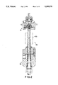
- An extrusion die assembly 30 according to one embodiment of the invention is shown in FIGS. 2 to 5 and consists of an upper or melt die portion 31 and a lower or quench tube die portion 32 coupled together by a union 33.
- the melt die portion 31 which is shown on an enlarged scale in FIG. 3, has a body 34 having an inlet 35 for receiving membrane forming dope and an inlet 36 for receiving coating fluid.
- the body has a central bore 37 and at its upper end there is a closure plate 38 having an axial passageway 39 for receiving a lumen forming fluid.
- the plate 38 is secured to the body 34 by bolts 40 and a seal is provided by "O" ring 41.
- nozzle member 42 which depends from the plate 38.
- the axial passageway 39 is reduced in diameter at its lower end where it passes through the tapered end 43 of nozzle member 42.
- the nozzle member 42 is sealed in the body 34 by "O" ring 44.
- the passageway 39 corresponds to passageway 11 of FIG. 1.
- the dope inlet 35 leads to a dope delivery passageway 45 in communication with an annular chamber 46 formed in the outer surface of nozzle 42. Dope is discharged from the chamber 46 into passageway 47 which exits into a tapered annular fibre forming tube 48 defined between the outer face of the nozzle 42 and a recess 49 formed in die plate 50.
- the fibre forming tube 48 has an upper conical portion 48a and a lower conical portion 48b.
- the upper portion 48a is inclined at a larger angle to the vertical than the lower portion 48b.
- the angle of inclination of the upper portion is from 30° to 60° from the axis and that of the lower portion is from 1° to 10° from the axis.
- the angle from the axis on the upper portion of nozzle 42 is 44° and on the upper portion of the die plate 50 is 50° and on the lower portion of nozzle 42 is 3° and on the lower portion of ringplate 50 is 5°.
- the tapered tube 48 provides a neck-down ratio (that is the ratio of the molten dope at the bottom of the tube 48 to diameter of the finished fibre) of 2.1 to 1.
- the neck down ratio may be in the range of 1:4 to 10:1.
- the coating fluid inlet 36 leads to a coating fluid delivery passageway 51 in communication with an annular chamber 52 formed by a recess in the bottom of the body 34 and the die plate 50. Coating fluid is discharged from chamber 52 into passageways 53 formed in the die plate 50 which exit into an annular chamber 54 formed between the bottom of the die plate 50 and ring plate 51.
- the ring plate 51 is secured to the body 34 by bolt 55.
- "O" ring 56 provides a seal between the ring plate 51, die plate 50 and body 34 and
- "O" ring 57 provides a seal between die plate 50 and body 34.
- a central bore 58 of the stem portion 59 of the ring plate 51 receives the fibre which is retained in hollow form by the lumen fluid and which is coated with the coating fluid.
- the quench tube portion 32 which is shown on an enlarged scale in FIG. 4 has a body portion 60 and a connector plate 61 secured thereto by bolt 62. "O" ring 63 provides a seal between the body 60 and plate 61.
- the body 60 as a quench fluid inlet 64 which leads to a quench fluid chamber 65 formed by a recess 66 formed in the body 60.
- a quench oil diffusor 67 having an axial bore 68. Passageways 69 connect the chamber 65 to the bore 68.
- FIG. 5 is an enlarged view of the discharge nozzle 42 which, in this instance, is modified to be in the nature of a needle 80 having a plurality of protrusions 81 which act to self centre the needle 80 within the chamber 48.
- the extrusion line shown in FIG. 6 includes a vessel 90 containing a membrane forming solution or dope.
- a heating jacket 91 coupled to a heating oil system (not shown) by lines 92 and 93.
- Dope from the vessel 90 is drawn through line 94 and valve 95 by gear pump 96. From the gear pump 96, the dope passes through filter 97 having a heating jacket 98 coupled to the heating oil system by lines 99 and 100.
- dope line 94 branches into four lines 94a, 94b, 94c and 94d which lead to extrusion die heads 101, 102, 103 and 104 respectively.
- Each die head has a melt portion 105 of the kind described in relation to FIG. 3 and a quench tube portion 106 of the kind described in relation to FIG. 4.
- Lines 107 represent the formed hollow fibres which are extruded from the die heads 101, 102, 103 and 104. The hollow fibres are wound onto reels (not shown).
- a vessel 108 containing a quench fluid has a heating jacket 109 coupled to the oil heating system by lines 110 and 111.
- Quench fluid is drawn through line 112 and valve 113 by gear pump 114. Downstream of the pump 114, the line 112 branches into four lines 112a, 112b, 112c and 112d which lead to the respective quench tube portions 106 of the die heads 101, 102, 103 and 104. After passing through the tube portions 106 the quench fluid is collected in reservoir 117 and returned to vessel 108 through line 118.
- a lumen forming fluid is introduced through line 119 and valve 120. Downstream of the valve 120, line 119 branches into line 121, 122, 123 and 124 which lead to the respective melt portions 105 of the die heads 101, 102, 103 and 104.
- the various pipes of the installation are insulated and all parameters are controlled by a microprocessor.
- a dope was formed by mixing and then heating 2600 gram of polypropylene pellets, 7300 gram of TERIC N2 and 100 gram of anti-oxidant ETHANOX 330 (ETHANOX & TERIC are Registered Trade Marks).
- TERIC N2 is nonylphenoxyethoxyethanol. The temperature of the dope was raised to above 220° C. with agitation under vacuum to ensure that that the mixture became homogeneous. The dope was then extruded through the quadruple passage die at a temperature of 220° C.
- the vessel 90 was held under a vacuum of -96 kPa and the oil heating system maintained at 245° C. Mixing was commenced when the temperature of the vessel 90 was 160° C. The mixing and heating time was 240 minutes. During extrusion the lumen forming nitrogen gas was maintained at 200 kPa. The filter 97 had an average pore diameter of 20 micron and the pressure drop across the filter was 50 kPa.
- Nitrogen was used as the lumen forming fluid and soybean oil as the coating fluid and quenching fluid.
- the dope flow rate was 22 cc/min
- the quench pump flow rate was 1750 cc/min.
- the circularity of the fibre prior to extraction of the solvent was 95% and the break extension was 175%.
- the physical characteristics of the fibre were:
- the structure of the fibre so formed was generally lacey.
- the lacey structure does not lend itself to a precise qualitative description in terms used to describe prior art membranes such as cells and pores.
- cells relate to spheres and pores relate to cylinders.
- the parts of the lacey structure where one cavity intersects another may be equivalent to a "cell” and the actual intersection itself a "pore”.
- Topologically, such "cells" of the lacey structure relate to adjacent spheres and such "pores" relate to circles formed by their intersection whereas in the prior art the cells relate to separated spheres and the pores relate to the connecting cylinders.
- the lacey structure has alveoli which are larger cavities than cells and these connect to a larger number of "cells".
- the lacey structure occupies the spaces between the alveoli.
- a typical lacey structure may have substantially spherical "cells" of between 0.1 to 5 micron which have substantially circular "pores" of 0.1 to 0.5 micron interconnecting the cells to each other.
- the "pores” also connect the cells to alveoli of about 8 to 20 micron. Water Permeability tests showed that the permeability of a typical fibre from outside to lumen was one third of the permeability from lumen to outside.
- Surface pore modification may be effected by both temperature control and variation of the composition of the coating fluid.
- Membranes can be prepared having elongated pores in the axial direction but with symmetrical morphology in the radial and circumferential directions.
- Surface porosity can be varied in radial porosity from a "skin" through to complete radial isotropy and further to having a surface that is more porous than the remainder of the membrane (reverse asymmetry).
- the coating fluid mixes significantly with the molten polymer to a greater extent than the quench fluid mixes when the coating fluid is omitted.
- the coating fluid controls the surface porosity of the membrane.
- the hot coating fluid ameliorates the sudden cooling effect of the quench fluid on the dope.
- the coating fluid is a separate, co-extrusion, and is neither part of the membrane extrusion nor the quench co-extrusion.
- the fibre travels down the quench tube at a significantly different linear speed from the quench fluid.
- the extruded fibre travels at a speed three to four times faster than the average speed of the quench fluid.
- Such a speed difference calculated on the average speed also means that the fibre travels at a speed about double the maximum speed of the quench fluid.
- the average and maximum speed of the quench fluid above are taken as the speed with no fibre present.
- any saturated vapour may be used as may a wide variety of liquids.
- nitrogen or a saturated vapour
- it has the effect of reducing the lumenal surface pore size, giving greater asymmetry.
- Use of a saturated vapour has the property that it will condense in the lumen under cooling, allowing the quench fluid to pass through the porous walls, and give some measure of mechanical compression to the solidifying membrane.
- polypropylene is the presently preferred thermoplastic polymer
- the following polymers may be used:
- x+y 2
- BR1J 92 is a polyoxyethylene (2) oleyl alcohol.
- Other solvents which may be used in carrying out the process of the invention include:
- (l) POE fatty alcohols such as CIRRASOL EN-MB and CIRRASOL EN-MP
- ATLAS, ATMER, CIRRASOL and RENEX are Registered Trade Marks.
- the same substance may be used as the coating, lumen, or quench fluids.
- the lumen-forming fluid may be selected from a wide variety of substances such as soybean oil or an inert gas such as nitrogen. Water may be used as the quench fluid.
- Other substances which may be used as the lumen forming fluid, the coating fluid and the quenching fluid include:
- the dimensions of the fibre were 322 micron lumen diameter and 671 micron outside diameter.
- the resulting fibre had a water permeability of 106 ml/min/m at 96 kPa, 367 ml/min/m at 398 kPa, and 478 ml/min/m at 599 kPa, a mean pore size of 0.301 micron and 90.7% pores above 0.16 micron.
- the dimensions of the fibre were 324 micron lumen diameter and 652 micron outside diameter.
- the resulting fibre had a water permeability of 126 ml/min/m at 96 kPa, 430 ml/min/m at 398 kPa, and 543 ml/min/m at 599 kPa, a mean pore size of 0.380 micron and 95.2% pores above 0.16 micron.
- the dimensions of the fibre were 323 micron lumen diameter and 640 micron outside diameter.
- the resulting fibre had a water permeability of 94 ml/min/m at 95 kPa, 330 ml/min/m at 396 kPa, and 448 ml/min/m at 598 kPa, a mean pore size of 0.310 micron and 87.9% pores above 0.16 micron.
- the dimensions of the fibre were 320 micron lumen diameter and 627 micron outside diameter.
- the resulting fibre has a water permeability of 80 ml/min/m at 98 kPa, 288 ml/min/m at 399 kPa, and 393 ml/min/m at 600 kPa, a mean pore size of 0.260 micron and 80.9% pores above 0.16 micron.
- the dimensions of the fibre were 325 micron lumen diameter and 642 micron outside diameter.
- the resulting fibre had a water permeability of 73 ml/min/m at 98 kPa, 288 ml/min/m at 399 kPa, and 393 ml/min/m at 600 kPa, a mean pore size of 0.260 micron and 80.9% pores above 0.16 micron.
- Hoechst polypropylene PPN1060F was dissolved in 18.25 kg TERIC N2 with 0.25 kg antioxidant Ethanox 330 and extruded at a temperature of 230° C. with soybean oil as the lumen, coating and quench .fluids.
- the quench fluid temperature was 30.1° C.
- the nominal dimensions of the fibre were 320 micron lumen diameter and 650 micron outside diameter.
- the resulting fibre had a water permeability of 68 ml/min/m at 95 kPa, 288 ml/min/m at 402 kPa, and 347 ml/min/m at 600 kPa, a mean pore size of 0.270 micron and 80.1% pores above 0.16 micron.
- the dimensions of the fibre were 310 micron lumen diameter and 599 micron outside diameter.
- the resulting fibre had a water permeability of 52 ml/min/m at 96 kPa, 241 ml/min/m at 397 kPa, and 305 ml/min/m at 598 kPa, a mean pore size of 0.322 micron and 65.7% pores above 0.16 micron.
- Shell polypropylene LY6100 was dissolved in a mixture of 9.8 kg soybean oil and 4.6 kg castor oil with 0.2 kg antioxidant Ethanox 330 and extruded at a temperature of 195° C. with soybean oil as the lumen, coating and quench fluids.
- the quench fluid temperature was 26.2° C.
- the nominal dimensions of the fibre were 320 micron lumen diameter and 650 micron outside diameter.
- the resulting fibre had a bubble point of 175 kPa, a mean pore size of 0.3 micron and 87.4% pores above 0.16 micron.
- the nominal dimensions of the fibre were 320 micron lumen diameter and 650 micron outside diameter.
- the resulting fibre had a bubble point of 133 kPa, a mean pore size of 0.45 micron and 100.0% pores above 0.16 micron.
- Hoechst polypropylene PPR1060F was dissolved in a mixture of 10.8 kg soybean oil and 5.0 kg castor oil and extruded at a temperature of 186° C. with soybean oil as the lumen, coating and quench fluids.
- the quench fluid temperature was 27.5° C.
- the nominal dimensions of the fibre were 320 micron lumen diameter and 650 micron outside diameter.
- the resulting fibre had a bubble point of 245 kPa, a mean pore size of 0.19 micron and 86.2% pores above 0.16 micron.
- the nominal dimensions of the fibre were 320 micron lumen diameter and 650 micron outside diameter.
- the resulting fibre had a bubble point of 140 kPa, a mean pore size of 0.24 micron and 89.6% pores above 0.16 micron.
- the nominal dimensions of the fibre were 320 micron lumen diameter and 650 micron outside diameter.
- the resulting fibre had a bubble point of 175 kPa, a mean pore size of 0.23 micron and 82.8% pores above 0.16 micron.
- the nominal dimensions of the fibre were 320 micron lumen diameter and 650 micron outside diameter.
- the resulting fibre had a bubble point of 280 kPa, a mean pore size of 0.18 micron and 83.4% pores above 0.16 micron.
Abstract
Description
______________________________________
Lumen                 340 micron
Outer diameter        640 micron
Circularity
Concentricity
Bubble Point          >170 kPa
% pores above 0.16 micron
                      >50%
Mean pore size        0.20 micron
Water Permeability at 50 kPa
                      >40 cc/min/m
Yield force           0.8 N
Break force           1.0 N
Break extension       >150%
Surface pore
width (nominal)       1 micron
______________________________________
Claims (18)
Priority Applications (2)
| Application Number | Priority Date | Filing Date | Title |
|---|---|---|---|
| US08/013,952 US5395570A (en) | 1988-11-10 | 1993-02-05 | Hollow fibre membrane extrusion |
| US08/378,523 US5698101A (en) | 1990-07-09 | 1995-01-26 | Hollow fiber membranes |
Applications Claiming Priority (4)
| Application Number | Priority Date | Filing Date | Title |
|---|---|---|---|
| AUPJ1395 | 1988-11-10 | ||
| AUPJ139588 | 1988-11-10 | ||
| US07/536,650 US5318417A (en) | 1988-11-10 | 1989-11-10 | Extrusion head for forming polymeric hollow fiber |
| US08/013,952 US5395570A (en) | 1988-11-10 | 1993-02-05 | Hollow fibre membrane extrusion |
Related Parent Applications (3)
| Application Number | Title | Priority Date | Filing Date |
|---|---|---|---|
| US07/536,650 Continuation-In-Part US5318417A (en) | 1988-11-10 | 1989-11-10 | Extrusion head for forming polymeric hollow fiber |
| US07/536,650 Division US5318417A (en) | 1988-11-10 | 1989-11-10 | Extrusion head for forming polymeric hollow fiber |
| US07/941,376 Continuation-In-Part US5277851A (en) | 1988-11-10 | 1992-09-04 | Process of making a porous hollow fiber membrane |
Related Child Applications (1)
| Application Number | Title | Priority Date | Filing Date |
|---|---|---|---|
| US08/378,523 Continuation-In-Part US5698101A (en) | 1990-07-09 | 1995-01-26 | Hollow fiber membranes |
Publications (1)
| Publication Number | Publication Date |
|---|---|
| US5395570A true US5395570A (en) | 1995-03-07 |
Family
ID=25643580
Family Applications (2)
| Application Number | Title | Priority Date | Filing Date |
|---|---|---|---|
| US07/536,650 Expired - Lifetime US5318417A (en) | 1988-11-10 | 1989-11-10 | Extrusion head for forming polymeric hollow fiber |
| US08/013,952 Expired - Lifetime US5395570A (en) | 1988-11-10 | 1993-02-05 | Hollow fibre membrane extrusion |
Family Applications Before (1)
| Application Number | Title | Priority Date | Filing Date |
|---|---|---|---|
| US07/536,650 Expired - Lifetime US5318417A (en) | 1988-11-10 | 1989-11-10 | Extrusion head for forming polymeric hollow fiber |
Country Status (1)
| Country | Link |
|---|---|
| US (2) | US5318417A (en) |
Cited By (13)
| Publication number | Priority date | Publication date | Assignee | Title |
|---|---|---|---|---|
| US5571415A (en) * | 1994-11-02 | 1996-11-05 | Rohm And Haas Company | Method for preparing porous polymer structures |
| US5762840A (en) * | 1996-04-18 | 1998-06-09 | Kimberly-Clark Worldwide, Inc. | Process for making microporous fibers with improved properties |
| WO2002036327A1 (en) * | 2000-11-03 | 2002-05-10 | Gkss-Forschungszentrum | Device for producing a polymer membrane |
| US6495041B2 (en) * | 1999-04-20 | 2002-12-17 | Asahi Kasei Kogyo Kabushiki Kaisha | Method for purifying aqueous suspension |
| US20030232184A1 (en) * | 2002-06-14 | 2003-12-18 | Toray Industries, Inc. | Porous membrane and method for manufacturing the same |
| US20040173933A1 (en) * | 2001-07-16 | 2004-09-09 | Wolfgang Albrecht | Double-layer hollow membrane for bio-reactor applications |
| US20070138682A1 (en) * | 2005-12-21 | 2007-06-21 | Young-Keun Lee | Microporous film of semicrystalline polymers and method for preparing the same |
| WO2007115368A1 (en) * | 2006-04-07 | 2007-10-18 | The University Of Queensland | Porous polymer structures |
| US20090286894A1 (en) * | 2006-04-07 | 2009-11-19 | Justin John Cooper-White | Porous polymer blend structures |
| US20110017661A1 (en) * | 2006-11-21 | 2011-01-27 | Arkema Inc. | Caustic resistant membrane |
| US20120085698A1 (en) * | 2009-12-07 | 2012-04-12 | Xinhao Yang | Method for preparing composite multilayer porous hollow membrane and device and product thereof |
| US11077407B2 (en) | 2016-05-31 | 2021-08-03 | Toray Industries, Inc. | Porous hollow-fiber membrane and production process therefor |
| US11369925B2 (en) * | 2017-02-28 | 2022-06-28 | Toray Industries, Inc. | Composite hollow-fiber membrane and production method therefor |
Families Citing this family (24)
| Publication number | Priority date | Publication date | Assignee | Title |
|---|---|---|---|---|
| US5686128A (en) * | 1995-08-31 | 1997-11-11 | Nabisco Technology Company | Apparatus and method for triple co-extruding a snack product |
| US6413070B1 (en) * | 1997-04-11 | 2002-07-02 | Cuno Incorporated | System for manufacturing reinforced three-zone microporous membrane |
| US6361583B1 (en) | 2000-05-19 | 2002-03-26 | Membrane Technology And Research, Inc. | Gas separation using organic-vapor-resistant membranes |
| US6592650B2 (en) | 2000-05-19 | 2003-07-15 | Membrane Technology And Research, Inc. | Gas separation using organic-vapor-resistant membranes and PSA |
| US6544316B2 (en) | 2000-05-19 | 2003-04-08 | Membrane Technology And Research, Inc. | Hydrogen gas separation using organic-vapor-resistant membranes |
| US6572679B2 (en) | 2000-05-19 | 2003-06-03 | Membrane Technology And Research, Inc. | Gas separation using organic-vapor-resistant membranes in conjunction with organic-vapor-selective membranes |
| US6361582B1 (en) | 2000-05-19 | 2002-03-26 | Membrane Technology And Research, Inc. | Gas separation using C3+ hydrocarbon-resistant membranes |
| US6572680B2 (en) | 2000-05-19 | 2003-06-03 | Membrane Technology And Research, Inc. | Carbon dioxide gas separation using organic-vapor-resistant membranes |
| US6579341B2 (en) | 2000-05-19 | 2003-06-17 | Membrane Technology And Research, Inc. | Nitrogen gas separation using organic-vapor-resistant membranes |
| KR100384799B1 (en) * | 2000-10-30 | 2003-05-22 | 주식회사 무 등 | Apparatus for extruding tube of thermoplastic resin |
| US7264836B2 (en) * | 2003-03-21 | 2007-09-04 | Kraft Foods Holdings, Inc. | Production of triple coextruded baked bar goods |
| US7470119B2 (en) * | 2004-05-18 | 2008-12-30 | Wm. Wrighley Jr. Company | Confection center fill apparatus and method |
| US20060034976A1 (en) * | 2004-08-12 | 2006-02-16 | Cotten Gerald B | Dual textured swirled confections |
| US7643133B2 (en) * | 2006-09-01 | 2010-01-05 | Goodrich Corporation | Air cargo power drive unit for detecting motion of an overlying cargo container |
| CA2659409C (en) | 2006-09-29 | 2014-05-20 | General Mills, Inc. | Apparatus and methods for fabricating food items |
| US7842214B2 (en) * | 2007-03-28 | 2010-11-30 | 3M Innovative Properties Company | Process for forming microporous membranes |
| IN2012DN00941A (en) | 2009-07-06 | 2015-04-03 | Sekisui Chemical Co Ltd | |
| US9975084B2 (en) | 2014-02-19 | 2018-05-22 | Membrane Technology And Research, Inc. | Fluid separation processes using membranes based on fluorinated and perfluorinated polymers |
| US9636632B2 (en) | 2014-02-19 | 2017-05-02 | Membrane Technology And Research, Inc | Gas separation membranes based on fluorinated and perfluorinated polymers |
| US9643124B2 (en) | 2014-02-19 | 2017-05-09 | Membrane Technology And Research, Inc. | Gas separation membranes based on fluorinated and perfluorinated polymers |
| US8828121B1 (en) | 2014-02-19 | 2014-09-09 | Membrane Technology And Research, Inc. | Gas separation membranes based on perfluorinated polymers |
| WO2016176468A1 (en) | 2015-04-29 | 2016-11-03 | Membrane Technology And Research, Inc. | Gas separation membranes based on fluorinated and perfluorinated polymers |
| WO2017069795A1 (en) | 2015-10-23 | 2017-04-27 | Membrane Technology And Research, Inc. | Gas separation membranes based on fluorinated and perfluorinated polymers |
| US11142849B1 (en) * | 2021-03-11 | 2021-10-12 | King Abdulaziz University | Method of forming hollow fiber using multi-angle spinneret |
Citations (21)
| Publication number | Priority date | Publication date | Assignee | Title |
|---|---|---|---|---|
| US3017238A (en) * | 1960-04-07 | 1962-01-16 | Hercules Powder Co Ltd | Method for solvent spinning polyolefins |
| US3378507A (en) * | 1961-12-20 | 1968-04-16 | Gen Electric | Producing microporous polymers |
| US3423491A (en) * | 1964-09-02 | 1969-01-21 | Dow Chemical Co | Permselective hollow fibers and method of making |
| GB1452400A (en) * | 1973-02-05 | 1976-10-13 | American Cyanamid Co | Melt spinning of refractory polymers |
| US4020230A (en) * | 1975-10-03 | 1977-04-26 | The Dow Chemical Company | Microporous polyethylene hollow fibers and process of preparing them |
| US4110153A (en) * | 1977-09-08 | 1978-08-29 | Ppg Industries, Inc. | Method of forming a microporous diaphragm |
| US4247498A (en) * | 1976-08-30 | 1981-01-27 | Akzona Incorporated | Methods for making microporous products |
| US4248924A (en) * | 1976-09-03 | 1981-02-03 | Sumitomo Electric Industries, Ltd. | Asymmetric porous film materials and process for producing same |
| AU7284081A (en) * | 1980-07-15 | 1982-01-21 | Akzo N.V. | Hollow fibre membrane for plasma separation |
| US4401567A (en) * | 1980-10-14 | 1983-08-30 | Mitsubishi Rayon Co., Ltd. | Microporous polyethylene hollow fibers |
| US4444716A (en) * | 1981-06-01 | 1984-04-24 | Terumo Kabushiki Kaisha | Method for manufacture of hollow fiber |
| EP0108601A2 (en) * | 1982-11-03 | 1984-05-16 | Akzo N.V. | Polypropylene membranes |
| DE3318180A1 (en) * | 1983-05-19 | 1984-11-22 | Akzo Gmbh, 5600 Wuppertal | Stabilised microporous microfiltration membranes made of polypropylene |
| US4519909A (en) * | 1977-07-11 | 1985-05-28 | Akzona Incorporated | Microporous products |
| US4564488A (en) * | 1978-07-31 | 1986-01-14 | Akzo Nv | Methods for the preparation of porous fibers and membranes |
| WO1986002282A1 (en) * | 1984-10-09 | 1986-04-24 | Millipore Corporation | Microporous membranes of ultrahigh molecular weight polyethylene |
| EP0180052A1 (en) * | 1984-10-09 | 1986-05-07 | TERUMO KABUSHIKI KAISHA trading as TERUMO CORPORATION | Hollow fiber membrane and method for manufacture thereof |
| US4594207A (en) * | 1982-02-15 | 1986-06-10 | Akzo Nv | Method for the production of porous bodies with adjustable total pore volume, adjustable pore size and adjustable pore walls |
| EP0217698A2 (en) * | 1985-08-29 | 1987-04-08 | TERUMO KABUSHIKI KAISHA trading as TERUMO CORPORATION | Method for the manufacture of a porous membrane for separation of blood components |
| US4666607A (en) * | 1983-07-30 | 1987-05-19 | Akzo Nv | Porous shaped bodies, and method and apparatus for the production thereof |
| AU8058487A (en) * | 1986-12-11 | 1988-06-16 | Minnesota Mining And Manufacturing Company | Microporous materials incorporating a nucleating agent and methods for making same |
-
1989
- 1989-11-10 US US07/536,650 patent/US5318417A/en not_active Expired - Lifetime
-
1993
- 1993-02-05 US US08/013,952 patent/US5395570A/en not_active Expired - Lifetime
Patent Citations (23)
| Publication number | Priority date | Publication date | Assignee | Title |
|---|---|---|---|---|
| US3017238A (en) * | 1960-04-07 | 1962-01-16 | Hercules Powder Co Ltd | Method for solvent spinning polyolefins |
| US3378507A (en) * | 1961-12-20 | 1968-04-16 | Gen Electric | Producing microporous polymers |
| US3423491A (en) * | 1964-09-02 | 1969-01-21 | Dow Chemical Co | Permselective hollow fibers and method of making |
| GB1452400A (en) * | 1973-02-05 | 1976-10-13 | American Cyanamid Co | Melt spinning of refractory polymers |
| US4020230A (en) * | 1975-10-03 | 1977-04-26 | The Dow Chemical Company | Microporous polyethylene hollow fibers and process of preparing them |
| US4115492A (en) * | 1975-10-03 | 1978-09-19 | The Dow Chemical Company | Process for preparing microporous polyethylene hollow fibers |
| US4247498A (en) * | 1976-08-30 | 1981-01-27 | Akzona Incorporated | Methods for making microporous products |
| US4248924A (en) * | 1976-09-03 | 1981-02-03 | Sumitomo Electric Industries, Ltd. | Asymmetric porous film materials and process for producing same |
| US4519909A (en) * | 1977-07-11 | 1985-05-28 | Akzona Incorporated | Microporous products |
| US4110153A (en) * | 1977-09-08 | 1978-08-29 | Ppg Industries, Inc. | Method of forming a microporous diaphragm |
| US4564488A (en) * | 1978-07-31 | 1986-01-14 | Akzo Nv | Methods for the preparation of porous fibers and membranes |
| AU7284081A (en) * | 1980-07-15 | 1982-01-21 | Akzo N.V. | Hollow fibre membrane for plasma separation |
| US4708799A (en) * | 1980-07-15 | 1987-11-24 | Klaus Gerlach | Hollow fiber membrane for plasma separation |
| US4401567A (en) * | 1980-10-14 | 1983-08-30 | Mitsubishi Rayon Co., Ltd. | Microporous polyethylene hollow fibers |
| US4444716A (en) * | 1981-06-01 | 1984-04-24 | Terumo Kabushiki Kaisha | Method for manufacture of hollow fiber |
| US4594207A (en) * | 1982-02-15 | 1986-06-10 | Akzo Nv | Method for the production of porous bodies with adjustable total pore volume, adjustable pore size and adjustable pore walls |
| EP0108601A2 (en) * | 1982-11-03 | 1984-05-16 | Akzo N.V. | Polypropylene membranes |
| DE3318180A1 (en) * | 1983-05-19 | 1984-11-22 | Akzo Gmbh, 5600 Wuppertal | Stabilised microporous microfiltration membranes made of polypropylene |
| US4666607A (en) * | 1983-07-30 | 1987-05-19 | Akzo Nv | Porous shaped bodies, and method and apparatus for the production thereof |
| WO1986002282A1 (en) * | 1984-10-09 | 1986-04-24 | Millipore Corporation | Microporous membranes of ultrahigh molecular weight polyethylene |
| EP0180052A1 (en) * | 1984-10-09 | 1986-05-07 | TERUMO KABUSHIKI KAISHA trading as TERUMO CORPORATION | Hollow fiber membrane and method for manufacture thereof |
| EP0217698A2 (en) * | 1985-08-29 | 1987-04-08 | TERUMO KABUSHIKI KAISHA trading as TERUMO CORPORATION | Method for the manufacture of a porous membrane for separation of blood components |
| AU8058487A (en) * | 1986-12-11 | 1988-06-16 | Minnesota Mining And Manufacturing Company | Microporous materials incorporating a nucleating agent and methods for making same |
Cited By (22)
| Publication number | Priority date | Publication date | Assignee | Title |
|---|---|---|---|---|
| US5571415A (en) * | 1994-11-02 | 1996-11-05 | Rohm And Haas Company | Method for preparing porous polymer structures |
| US5762840A (en) * | 1996-04-18 | 1998-06-09 | Kimberly-Clark Worldwide, Inc. | Process for making microporous fibers with improved properties |
| US6495041B2 (en) * | 1999-04-20 | 2002-12-17 | Asahi Kasei Kogyo Kabushiki Kaisha | Method for purifying aqueous suspension |
| WO2002036327A1 (en) * | 2000-11-03 | 2002-05-10 | Gkss-Forschungszentrum | Device for producing a polymer membrane |
| US7485249B2 (en) * | 2001-07-16 | 2009-02-03 | Gkss Forschungszentrum Geesthacht Gmbh | Double-layer hollow membrane for bio-reactor applications |
| US20040173933A1 (en) * | 2001-07-16 | 2004-09-09 | Wolfgang Albrecht | Double-layer hollow membrane for bio-reactor applications |
| AU2003241797B2 (en) * | 2002-06-14 | 2008-10-09 | Toray Industries, Inc. | Porous membrane and method of manufacturing the porous membrane |
| US7851024B2 (en) * | 2002-06-14 | 2010-12-14 | Toray Industries, Inc. | Porous membrane and method for manufacturing the same |
| US7258914B2 (en) * | 2002-06-14 | 2007-08-21 | Toray Industries, Inc. | Porous membrane and method for manufacturing the same |
| US20030232184A1 (en) * | 2002-06-14 | 2003-12-18 | Toray Industries, Inc. | Porous membrane and method for manufacturing the same |
| US20070084794A1 (en) * | 2002-06-14 | 2007-04-19 | Toray Industries, Inc. | Porous membrane and method for manufacturing the same |
| US20070138682A1 (en) * | 2005-12-21 | 2007-06-21 | Young-Keun Lee | Microporous film of semicrystalline polymers and method for preparing the same |
| WO2007115368A1 (en) * | 2006-04-07 | 2007-10-18 | The University Of Queensland | Porous polymer structures |
| US20090286894A1 (en) * | 2006-04-07 | 2009-11-19 | Justin John Cooper-White | Porous polymer blend structures |
| US8044108B2 (en) | 2006-04-07 | 2011-10-25 | The University Of Queensland | Porous polymer blend structures |
| US8222308B2 (en) | 2006-04-07 | 2012-07-17 | The University Of Queensland | Porous polymer structures |
| US20110017661A1 (en) * | 2006-11-21 | 2011-01-27 | Arkema Inc. | Caustic resistant membrane |
| US9327247B2 (en) | 2006-11-21 | 2016-05-03 | Arkema Inc. | Caustic resistant membrane |
| US20120085698A1 (en) * | 2009-12-07 | 2012-04-12 | Xinhao Yang | Method for preparing composite multilayer porous hollow membrane and device and product thereof |
| US8967391B2 (en) * | 2009-12-07 | 2015-03-03 | Memstar (Guangzhou) Co., Ltd | Method for preparing composite multilayer porous hollow membrane and device and product thereof |
| US11077407B2 (en) | 2016-05-31 | 2021-08-03 | Toray Industries, Inc. | Porous hollow-fiber membrane and production process therefor |
| US11369925B2 (en) * | 2017-02-28 | 2022-06-28 | Toray Industries, Inc. | Composite hollow-fiber membrane and production method therefor |
Also Published As
| Publication number | Publication date |
|---|---|
| US5318417A (en) | 1994-06-07 |
Similar Documents
| Publication | Publication Date | Title |
|---|---|---|
| US5395570A (en) | Hollow fibre membrane extrusion | |
| EP0423249B1 (en) | Extrusion of hollow fibre membranes | |
| US5698101A (en) | Hollow fiber membranes | |
| US5489406A (en) | Method of making polyvinylidene fluoride membrane | |
| EP0527913B2 (en) | Method for making pvdf hollow fibre membranes | |
| US4399035A (en) | Polyvinylidene fluoride type resin hollow filament microfilter and process for producing the same | |
| US6074718A (en) | Self supporting hollow fiber membrane and method of construction | |
| CA2480432A1 (en) | Hollow fibres | |
| US5277851A (en) | Process of making a porous hollow fiber membrane | |
| AU621164B2 (en) | Extrusion of hollow fibre membranes | |
| AU653528B2 (en) | Porous PVdF membranes | |
| JP2512909B2 (en) | Method for producing hollow fiber porous membrane | |
| AU621428B2 (en) | Porous membranes | |
| JPH01192811A (en) | Production of porous hollow fiber |
Legal Events
| Date | Code | Title | Description |
|---|---|---|---|
| STCF | Information on status: patent grant |
Free format text: PATENTED CASE |
|
| FEPP | Fee payment procedure |
Free format text: PAYOR NUMBER ASSIGNED (ORIGINAL EVENT CODE: ASPN); ENTITY STATUS OF PATENT OWNER: LARGE ENTITY |
|
| FPAY | Fee payment |
Year of fee payment: 4 |
|
| FPAY | Fee payment |
Year of fee payment: 8 |
|
| AS | Assignment |
Owner name: U. S. FILTER WASTEWATER GROUP, INC., PENNSYLVANIA Free format text: ASSIGNMENT OF ASSIGNORS INTEREST;ASSIGNOR:PALL FILTRATION AND SEPARATIONS PTY LIMITED;REEL/FRAME:014734/0620 Effective date: 20040615 |
|
| AS | Assignment |
Owner name: PALL FILTRATION AND SEPARATIONS PTY LIMITED, AUSTR Free format text: CHANGE OF NAME;ASSIGNOR:USF FILTRATION PTY LIMITED;REEL/FRAME:014743/0830 Effective date: 20020510 Owner name: USF FILTRATION LIMITED, AUSTRALIA Free format text: CHANGE OF NAME;ASSIGNOR:MEMTEC LTD;REEL/FRAME:014743/0812 Effective date: 19980424 Owner name: USF FILTRATION PTY LIMITED, AUSTRALIA Free format text: CHANGE OF NAME;ASSIGNOR:USF FILTRATION LIMITED;REEL/FRAME:014743/0839 Effective date: 20000929 |
|
| AS | Assignment |
Owner name: MEMTEC LIMITED, AUSTRALIA Free format text: ASSIGNMENT OF ASSIGNORS INTEREST;ASSIGNORS:KOPP, CLINTON VIRGIL;STREETON, ROBERT JOHN WILLIAM;KHOO, PAUL SOO-HOCK;REEL/FRAME:014770/0453 Effective date: 19920424 |
|
| FPAY | Fee payment |
Year of fee payment: 12 |
|
| AS | Assignment |
Owner name: SIEMENS WATER TECHNOLOGIES CORP., MASSACHUSETTS Free format text: MERGER;ASSIGNOR:U.S. FILTER WASTEWATER GROUP, INC.;REEL/FRAME:018442/0090 Effective date: 20060804 |
|
| AS | Assignment |
Owner name: SIEMENS WATER TECHNOLOGIES HOLDING CORP., PENNSYLV Free format text: MERGER;ASSIGNOR:SIEMENS WATER TECHNOLOGIES CORP.;REEL/FRAME:026106/0467 Effective date: 20110401 |
|
| AS | Assignment |
Owner name: SIEMENS INDUSTRY, INC., GEORGIA Free format text: MERGER;ASSIGNOR:SIEMENS WATER TECHNOLOGIES HOLDING CORP.;REEL/FRAME:026138/0593 Effective date: 20110401 |