US5402341A - Method and apparatus for four wheel steering control utilizing tire characteristics - Google Patents
Method and apparatus for four wheel steering control utilizing tire characteristics Download PDFInfo
- Publication number
- US5402341A US5402341A US07/866,771 US86677192A US5402341A US 5402341 A US5402341 A US 5402341A US 86677192 A US86677192 A US 86677192A US 5402341 A US5402341 A US 5402341A
- Authority
- US
- United States
- Prior art keywords
- vehicle
- tire
- wheels
- steerable wheels
- wheel
- Prior art date
- Legal status (The legal status is an assumption and is not a legal conclusion. Google has not performed a legal analysis and makes no representation as to the accuracy of the status listed.)
- Expired - Lifetime
Links
Images


Classifications
-
- B—PERFORMING OPERATIONS; TRANSPORTING
- B62—LAND VEHICLES FOR TRAVELLING OTHERWISE THAN ON RAILS
- B62D—MOTOR VEHICLES; TRAILERS
- B62D7/00—Steering linkage; Stub axles or their mountings
- B62D7/06—Steering linkage; Stub axles or their mountings for individually-pivoted wheels, e.g. on king-pins
- B62D7/14—Steering linkage; Stub axles or their mountings for individually-pivoted wheels, e.g. on king-pins the pivotal axes being situated in more than one plane transverse to the longitudinal centre line of the vehicle, e.g. all-wheel steering
- B62D7/15—Steering linkage; Stub axles or their mountings for individually-pivoted wheels, e.g. on king-pins the pivotal axes being situated in more than one plane transverse to the longitudinal centre line of the vehicle, e.g. all-wheel steering characterised by means varying the ratio between the steering angles of the steered wheels
- B62D7/159—Steering linkage; Stub axles or their mountings for individually-pivoted wheels, e.g. on king-pins the pivotal axes being situated in more than one plane transverse to the longitudinal centre line of the vehicle, e.g. all-wheel steering characterised by means varying the ratio between the steering angles of the steered wheels characterised by computing methods or stabilisation processes or systems, e.g. responding to yaw rate, lateral wind, load, road condition
Definitions
- the present invention is related to a four wheel steering system for use on a vehicle having front and rear steerable wheels.
- front steerable wheels are manually controlled by the vehicle operator and the rear steerable wheels, mechanically or electronically are controlled, in response to the position of the front wheels and other vehicle operating parameters, such as vehicle speed.
- rear steerable wheels By adjusting the rear steerable wheels, vehicle handling can be improved.
- U.S. Pat. Nos. 4,441,572, 4,645,025, 4,679,809 and 4,901,811 relate to four wheel steering systems wherein the steering angle of the rear wheels is determined based on parameters, such as sensed vehicle speed, front and/or rear wheel steering angles and the like.
- the '811 reference discloses a vehicle steering system for adjusting tire characteristics.
- the vehicle comprises front wheels, each being equipped with a front tire; and rear wheels, each being equipped with a rear tire having a rear tire characteristic which is different from the front tire characteristic.
- the vehicle also comprises a rear wheel steering system for steering the rear wheels and controlling means for adjusting the rear tire characteristic by steering the rear wheels in a predetermined first cornering condition of the vehicle.
- U.S. Pat. Nos. 4,412,594, 4,690,431, 4,718,685 and 5,019,982 relate to four wheel steering systems wherein the rear steering angle is determined based on inputs including a signal representative of an actual vehicle motion variable, such as yaw rate or lateral acceleration. More particularly, the '982 reference discloses a method of controlling the rear wheels of a four wheel steering vehicle having front road wheels which can be turned by steering action, rear wheels which can be turned in response to the turning of the front wheels and means for detecting lateral acceleration applied to the vehicle. This arrangement allows for variable control of the steer angle ratio of a rear steer angle relative to a front steer angle based on the lateral acceleration.
- U.S. Pat. Nos. 4,865,146 and 5,014,801 disclose a four wheel steering system wherein the rear steering angle is calculated based on vehicle parameters, such as steering torque, and U.S. Pat. No. 4,936,401, assigned to the assignee of the present invention, discloses a system for steering front and rear steerable wheels of a vehicle.
- a method of improving vehicle handling for use with a vehicle having manually operable front steerable wheels and electronically controlled rear steerable wheels.
- the method comprises the steps of calculating a desired rear steer angle based on vehicle speed and front wheel angle and determining if the vehicle is operating in the nonlinear region of the front tires.
- the method also comprises the steps of calculating a handling term if the vehicle is operating in the nonlinear region of the front tires, modifying the desired rear steer angle based on the handling term and steering the rear steerable wheels toward the modified desired rear steer angle.
- FIG. 1 is a perspective view of a vehicle having front and rear steerable wheels, for use with the present invention
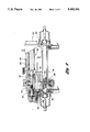
- FIG. 2 is a partial cross-sectional view of a rear steering gear assembly for use with the present invention
- FIG. 3 is a block diagram of a controller for controlling the rear steerable wheels
- FIG. 4 is a block diagram of a simple bicycle model utilized in the development of the control strategy of the present invention.
- FIG. 5a is a front view of the vehicle shown in FIG. 1 illustrating various force vectors
- FIG. 5b is a plan view in phantom representation of the vehicle shown in FIG. 1 illustrating the front steerable wheels being in-phase with the rear steerable wheels;
- FIG. 6 is a block diagram of a general proportional steer controller for steering the rear steerable wheels
- FIG. 7 is a graphical representation of the ratio of rear steer angle to front steer angle plotted versus vehicle speed
- FIG. 8 is a block diagram of a general closed-loop controller for steering the rear steerable wheels
- FIG. 9 is a block diagram of the closed-loop yaw rate (CLYR) controller for use with the present invention.
- CLYR closed-loop yaw rate
- FIG. 10 is a block diagram of a general open-loop, or feedforward, controller for steering the rear steerable wheels;
- FIGS. 11a and 11b are block diagrams of the open-loop feedforward controller which implements the control strategy of the present invention.
- FIG. 12 is a graphical representation of the open loop, or feedforward, control gains for use with the present invention.
- FIG. 13 is a graphical representation of the lateral tire forces versus tire slip angle and an associated linear approximation
- FIG. 14 is a graphical representation of the non-linear tire model utilized by the present invention.
- FIG. 15 is a graphical representation of front steering rack position plotted versus vehicle speed illustrating the boundary between a linear tire approximation and a saturated tire approximation
- FIG. 16 is a flow chart illustrating the control strategy of the present invention.
- FIG. 1 there is illustrated a vehicle shown generally by reference numeral 10, equipped with front steerable wheels 12 and rear steerable wheels 14.
- the front steerable wheels 12 are steered by a front steering gear assembly 16 and the rear steerable wheels 14 are steered by a rear steering gear assembly 18.
- the front steerable wheels 12 are manually operable by the vehicle operator and the rear steerable wheels 14 are controlled by a controller 20.
- the steering gear 18 is electronically controlled by the controller 20, seen in FIG. 1, and driven by a motor 22 having stator windings 24 and an armature 26.
- the motor 22 is a brushless DC motor commercially available from Sierracin/Magnedyne, of Carlsbad, Calif., United States of America.
- the rear steering gear 18 could be hydraulically driven.
- a motor shaft 30 and motor pinion 32 rotate in response to commands from the controller 20.
- the motor pinion 32 drives a face gear 34, which is mounted upon a pinion shaft 36.
- Rack pinion 38 which is formed at one end of the pinion shaft 36, meshes with teeth 40 which are formed on a rack 42.
- rack 42 will be caused to slide back and forth within a housing 44, thereby pushing or pulling steering rods (not specifically illustrated) and steering the rear steerable wheels 14.
- the steering system is described in greater detail in U.S. Pat. No. 4,936,401, issued to Baraszu et al. and assigned to the assignee of the present invention, which is hereby incorporated by reference.
- FIG. 3 there is shown a block diagram of the controller 20, which includes a microprocessor 50 and a motor controller 52.
- the microprocessor 50 is an 8096 microprocessor and is utilized to implement the four wheel steering control strategy.
- the motor controller 52 manages delivery of power to, and commutation of, motor 22, which is preferably driven with pulse-width modulated field effect transistors (FET).
- FET pulse-width modulated field effect transistors
- the microprocessor 50 and the motor controller 52 include random access and read-only memories (RAM/ROM), analog-to-digital converters, and the like, not specifically illustrated.
- the RAM memory is utilized as a temporary storage device for various data related to the operation of the rear steering gear 18 and the ROM stores the program which implements the four-wheel steering strategy of the present invention as well as other information, such as constants.
- the microprocessor 50 communicates with the motor controller via a digital signal link.
- the rear steering gear 18 utilizes a first sensor 56 for sensing the on-center position of the steering rack and a second sensor 58 to sense the position of the rack at any point along its path of travel.
- the sensor 56 is a Hall-effect sensor mounted within the steering gear housing 44.
- the Hall-effect sensor 56 is triggered by a magnet 60, which is rigidly attached to the rack 42 and which reciprocates therewith as the rack slides back and forth during steering motion.
- an electrical signal is sent to the controller 20 indicating the rear steering gear 18 is in the center position (i.e. zero steer angle).
- the second sensor 58 is an LVDT (linear variable differential transformer) which senses the position of rack 42 at any point along its path of travel so as to provide a steering position signal to the controller 20.
- the LVDT 58 provides a voltage signal to the controller 20 which is a direct indication of the position of the rack 42.
- the controller 20, utilizing signals from the Hall-effect sensor 56, LVDT 58 and a vehicle speed sensor (not specifically illustrated) actively controls the steer angles of the rear steering gear 18 so as to improve the handling performance of the vehicle 10, as described in greater detail herein below.
- the front steering gear 16 (not shown in detail) is similar to rear steering gear 18 and includes identical position sensors 56 and 58.
- FIG. 4 there is shown a block diagram of a simple bicycle model utilized in the development of the control strategy of the present invention.
- this linear model as discussed by J. Whitehead, Dept. of Mechanical Engineering, University of California, Davis, in his SAE Paper #880642 titled “Four Wheel Steering: Maneuverability and High Speed Stabilization,” published Feb. 29, 1988, (hereinafter the Whitehead reference) assumes that the vehicle speed (U) is constant, that vehicle lateral and rotational motions are generated only by lateral tire forces at the road surface and that steer angles are small and within the linear region of the tires mounted on the front and rear steerable wheels.
- the model has two state variables, lateral (sideslip) velocity of the center of gravity (v) and yaw rate (r).
- lateral (sideslip) velocity of the center of gravity (v) and yaw rate (r).
- v center of gravity
- r yaw rate
- the sum of the lateral tire forces equals the mass times the lateral acceleration, which is made up of the time derivative of lateral velocity plus the centripetal acceleration:
- the angular acceleration about the yaw axis can be written as follows:
- ⁇ r rear tire slip angle (rad);
- ⁇ f front wheel steer angle (rad);
- ⁇ r rear wheel steer angle (rad);
- J z rotational inertia about yaw axis
- K 1 gain parameter of CLYR controller
- K 2 gain parameter of CLYR controller
- K 3 gain parameter of CLYR controller
- the tire slip angles are measured as the difference between the tire plane, perpendicular to the axis of rotation, and the tire velocity vector.
- the model utilizes one user input ⁇ f and one control input ⁇ r .
- the "inner loop" control is common to all three controllers illustrated, and is basically a servo-position control loop which drives the rear steerable wheels to the commanded, or desired, rear steer angle.
- this loop should have a bandwidth larger than that of the driver's steering inputs and of the dominant steering responses, yaw rate and lateral acceleration. Since it is typically possible for a driver to generate up to 5 Hz steering inputs and vehicle dynamics have a cutoff frequency of about 2 Hz, an inner loop with a 10 Hz bandwidth provides adequate control. To ensure proper rear wheel alignment, the inner loop should have a control accuracy of about 1 mm to 2 mm (i.e. 0.25° to 0.5° of rear steer).
- the proportional controller steers the rear steerable wheels 14 to a proportion (variable and depending on vehicle speed) of the front steerable wheels 12, wherein ⁇ f represents the front rack position in terms of the steer angle, ⁇ r represents the rear rack position in terms of the steer angle, ⁇ re represents the estimated rear rack position, ⁇ rv represents the estimated rear rack velocity, ⁇ rd represents the desired rear rack position, u represents the vehicle speed, K d represents a velocity, or derivative, gain and K p represents a position gain.
- the ratio ⁇ r / ⁇ f is negative or out-of-phase for low speeds (e.g. ⁇ 25 mph) and is positive or in-phase for high vehicle speeds (e.g.
- FIG. 7 illustrates this ratio plotted against vehicle speed.
- Negative gains mean the rear steerable wheels 14 turn in the opposite direction or out-of-phase with the front steerable wheels 12. This strategy, in addition to eliminating steady-state sideslip, results in the vehicle 10 having a higher steering gain at low speeds and lower steady-state gain at high speeds. A higher low speed gain gives the vehicle a tighter turning radius, making the vehicle more maneuverable in tight spaces.
- a proportional steer strategy generates a lateral force before the vehicle produces a yaw rate, since the rear wheels 14 turn at the same time as the front wheels 12, allowing the vehicle to generate lateral acceleration and the resulting lateral movement quicker than a two-wheel steer (2 WS) vehicle.
- Proportional steer strategies have disadvantages.
- the steady-state gain of the vehicle from steering input to both yaw rate and lateral acceleration is greatly reduced for speeds above about 25 mph, which is perceived by the vehicle operator to be understeer.
- the proportional steer strategy degrades the transient handling performance. Specifically, the yaw rate response of the vehicle is degraded since the lateral acceleration response times are sped up.
- the proportional gain can be reduced from 75%-90%, which results in retention of some of the benefits without drastically changing the vehicle characteristics.
- FIG. 7 illustrates the proportional gain reduced by about 75% and a piecewise linear approximation (shown as a dashed line).
- Closed-loop controllers typically require feedback of vehicle parameters such as yaw rate (i.e. rotational velocity of the vehicle about its center of gravity) or lateral acceleration to achieve adequate control.
- the closed-loop yaw rate (CLYR) controller shown determines a desired rear rack position ( ⁇ r ) based on steering wheel input ( ⁇ s ), steering gear ratio (G), front rack position ( ⁇ f ) and wherein r d represents the desired yaw rate, r a represents the yaw rate acceleration, ⁇ rd represents the desired rear rack position, u represents the vehicle speed, K pr represents a position gain on yaw rate error and K dr represents a gain on the derivative of yaw rate.
- the gain K 1 is preferably set to equal a gain which converts front steering angle to a desired yaw rate
- the gain K 2 is preferably set equal to the value 1
- the gain K 3 is preferably set equal to a proportional gain on yaw rate error.
- a derivative feedback term on yaw rate is preferably added to help achieve a well-damped yaw response.
- the yaw rate measurement is passed through a 5 Hz single-pole high-pass filter to approximate a derivative and provide adequate differentiation for yaw signals within the bandwidth of the vehicle's yaw response, to yield the CLYR 4 WS control structure shown in FIG. 9.
- the conversion gain, K 1 is preferably determined from steering angle and vehicle speed for desired steady state yaw rate.
- a desired steady state yaw rate curve can be plotted and used to tune and validate the linear bicycle model.
- Another choice for the gains K 1 , K 2 and K 3 which dynamically maintain zero body sideslip is provided in the Whitehead reference as follows: ##EQU4##
- FIGS. 10 and 11 there is shown a block diagram of a general open-loop control strategy for a four wheel steer vehicle and a block diagram of the open-loop control strategy of the present invention, respectively.
- the general open-loop controller of FIG. 10 determines a desired rear rack position ( ⁇ rd ), based on desired front rack position ( ⁇ f ) and vehicle speed (u) and wherein ⁇ r represents the rear rack position, ⁇ re represents the estimated rear rack position, ⁇ rv represents the estimated rear rack velocity, ⁇ r ss represents the steady state desired rear steer angle, K d represents a velocity, or derivative, gain and K p represents a position gain.
- the open-loop, or feedforward, control strategy of the present invention utilizes a minimum number of sensors (no yaw sensor), does not require feedback of vehicle parameters and provides better handling in the nonlinear region of vehicle tires, as described in greater detail below.
- the idea behind an open-loop controller is that given adequate knowledge of the vehicle dynamics one can calculate a feedforward compensator which will provide the same performance as a closed-loop yaw rate feedback controller.
- the gains K 1 , K 2 and K 3 are preferably determined utilizing the zero body sideslip algorithm previously discussed. Alternatively, in-vehicle calibration could also be utilized.
- the transfer function having the form: ##EQU5## can be determined and applied as a feedforward control algorithm, where a 0 , a 1 , a 2 , b 1 and b 2 are dependent on the control gains and vehicle parameters of the model.
- the implementation of this transfer function with a "perfect" actuator is designed to keep body sideslip at zero and have similar performance as the CLYR.
- the preferred implementation involved inverting the filtering delay (i.e.
- FIG. 12 graphically illustrates the preferred controller gains which are gain scheduled over the speed range of the vehicle.
- a 4 WS system based on this linear model can introduce large amounts of understeer when driven in the non-linear region of the tires.
- the front tires will saturate first, limiting the possible yaw rate and lateral acceleration. If the controller does not compensate for this saturation, more lateral forces will be generated at the rear tires. These additional rear forces will be in the direction of understeer, making the car less maneuverable in handling situations.
- FIG. 14 there is shown a tire model implemented in the feedforward controller of the present invention.
- this model is linear for small slip angles (shown generally at reference point “A") but also includes a saturation region (shown generally at reference points "B").
- the controller can determine when the vehicle has reached a maximum steady state yaw and lateral acceleration to avoid adding excessive understeer. Additionally, by steering the rear steerable wheels back toward the out-of-phase direction at the point of maximum steady state yaw and lateral acceleration, the feedforward controller can actually improve vehicle transient performance and steady state attitude (i.e., the relationship of the vehicle's centerline to the vehicle's path of travel).
- the feedforward controller imitates the actions available from a closed-loop controller. Once the front tires are in saturation, the car cannot generate additional yaw as the steering wheel angle increases. As the CLYR controller identifies the increasing yaw error, the controller will begin to steer the rear steerable wheels toward the out-of-phase direction in proportion to the excess front wheel angle. To accomplish this with the feedforward controller, an additional term is added to the rear steer control command once the tires are in the saturation region, as described in greater detail herein below.
- a graph illustrates the front steering rack position plotted against the vehicle speed, to define the boundary between a linear tire approximation and a saturated tire approximation.
- the tires enter the saturation region at approximately 9 mm of front rack travel.
- the controller computes the additional term to be added to the rear steer control command by taking the difference between the front wheel angle and the tire saturation angle (from FIG. 15) and multiplying that difference by a handling gain.
- the open-loop controller emulates the CLYR controller at tire saturation.
- Control block 70 represents a low pass filter having a cutoff frequency of approximately 5 Hz which functions to remove sensor noise from the front rack position sensor measurement.
- Control block 72 operates to take the absolute value of the filtered front rack position signal.
- a table look-up is performed to determine the approximate front rack position at which the front tires begin to saturate. This table is shown graphically in FIG. 15. Preferably, tire saturation is based on front rack position and vehicle speed.
- the controller determines if the absolute value of the front rack position is in the nonlinear region of the front tires.
- Block 78 represents the handling gain (K h ), which is multiplied with the difference between the front rack position determined at block 72 and the nonlinear border rack position determined at block 74.
- the sign of the handling gain changed and, at block 82, the controller selects the version of the handling gain (i.e. positive or negative) which is out-of-phase with the front wheels.
- Control block 86 utilizes the output from block 76, block 82 and the value of zero ("0") output from block 84, to calculate the handling term. If, however, block 76 is "false" (i.e. the front tires are not in saturation), the handling term is zero ("0").
- the value of the calculated handling term is limited to a rack position of approximately ⁇ 6 mm.
- the measured front wheel angle is converted from radians to degrees at control block 90.
- the measured value of the front wheel angle is limited to approximately ⁇ 7.5°. Preferably, this limit is not applied at low speeds (e.g. ⁇ 25 mph) where larger wheel angles are possible.
- Control block 94 implements a low pass filter having a cutoff frequency of approximately 3 Hz, which functions to remove sensor noise from the front wheel angle signal.
- Control blocks 96 and 98 implement a high pass filter having a 15 Hz pole to provide the function of a differentiator.
- the control block 100 implements the filtering delay in calculating the vehicle speed as seen in the vehicle and control block 102 converts the vehicle speed from meters per second (m/S) to miles per hour (mph).
- a table look-up is performed to determine the gain (A 0 ), based on vehicle speed.
- the table values include the 75% reduction previously described.
- table look-ups are performed at control blocks 106 and 108, where the gains A 1 and A 2 are determined, respectively, based on vehicle speed.
- the gain A 2 is corrected (i.e. reduced by approximately 20%) at control block 110.
- the controller determines the desired rear wheel angle (°)according to the transfer function G(s) (previously described) by summing the value from control block 110 with the values from the multipliers 112 and 114.
- Control block 116 converts the desired rear wheel angle from degrees to a desired rear rack position (mm).
- the desired rear rack position is limited, at control block 118, to approximately ⁇ 6 mm. Preferably, this limit is about 20 mm for low vehicle speeds.
- the controller adds the handling term from block 88 to the desired rear rack position to steer the rear steerable wheels.
- the flow chart shown in FIG. 16 illustrates the operational steps taken by the feedforward controller of the present invention.
- the controller first reads system inputs, such as vehicle speed, front wheel angle and rear wheel angle utilizing a plurality of sensors, as previously described.
- system inputs such as vehicle speed, front wheel angle and rear wheel angle utilizing a plurality of sensors, as previously described.
- the controller gains A 0 , A 1 and A 2 are determined from a look-up table stored in a ROM memory, based on vehicle speed.
- the desired rear wheel angle ( ⁇ r ) is calculated utilizing the linear transfer function gains.
- the controller determines whether the front wheel angle ( ⁇ f ) has exceeded the tire saturation angle ( ⁇ s ) at the linear limit or border (see FIG. 13). If the front wheel angle does not exceed the tire saturation angle, the controller 26, at step 116, commands the rear steerable wheels 114 toward the calculated rear wheel angle. If the front wheel angle does exceed the tire saturation angle, the tires are operating in the non-linear region (see FIG. 15).
- an additional handling term ( ⁇ h ) is determined by the controller by subtracting the entire saturation angle from the front wheel angle and multiplying that result by a handling gain (K h ).
- the controller determines if the front wheel angle is greater than zero to determine whether the additional handling term should be added to or subtracted from the calculated rear wheel angle ( ⁇ r ). If the front wheel angle is greater than zero, at step 112, the additional handling term is subtracted from the rear wheel angle. If, however, the front wheel angle is less than zero, the additional handling term is added to the rear wheel angle determined at step 104. The rear steerable wheels are then steering toward this rear wheel angle ( ⁇ r ) at step 116. By steering the rear steerable wheels back toward the center or out-of-phase for severe corners, the feedforward controller emulates the operation of the CLYR controller during vehicle operation in the non-linear region.
Abstract
Description
mv+mru=F.sub.f +F.sub.r =C.sub.f α.sub.f +C.sub.r α.sub.r
J.sub.z r=C.sub.f aα.sub.f -C.sub.r bα.sub.r
Claims (11)
Priority Applications (1)
| Application Number | Priority Date | Filing Date | Title |
|---|---|---|---|
| US07/866,771 US5402341A (en) | 1992-04-06 | 1992-04-06 | Method and apparatus for four wheel steering control utilizing tire characteristics |
Applications Claiming Priority (1)
| Application Number | Priority Date | Filing Date | Title |
|---|---|---|---|
| US07/866,771 US5402341A (en) | 1992-04-06 | 1992-04-06 | Method and apparatus for four wheel steering control utilizing tire characteristics |
Publications (1)
| Publication Number | Publication Date |
|---|---|
| US5402341A true US5402341A (en) | 1995-03-28 |
Family
ID=25348368
Family Applications (1)
| Application Number | Title | Priority Date | Filing Date |
|---|---|---|---|
| US07/866,771 Expired - Lifetime US5402341A (en) | 1992-04-06 | 1992-04-06 | Method and apparatus for four wheel steering control utilizing tire characteristics |
Country Status (1)
| Country | Link |
|---|---|
| US (1) | US5402341A (en) |
Cited By (30)
| Publication number | Priority date | Publication date | Assignee | Title |
|---|---|---|---|---|
| US5515275A (en) * | 1992-03-03 | 1996-05-07 | Deutsche Forschungsanstalt Fur Luft- Und Raumfahrt E.V. | Control system for steering a road vehicle having both front-wheel steering and rear wheel steering |
| US5586031A (en) * | 1993-09-20 | 1996-12-17 | Kroll Fahrzeugbau-Umwelttechnik Gmbh | Road vehicle with all wheel steering, and process for steering |
| US5595089A (en) * | 1994-01-31 | 1997-01-21 | Aisin Seiki Kabushiki Kaisha | Actuator for steering rear wheels |
| US5648903A (en) * | 1995-07-10 | 1997-07-15 | Ford Global Technologies, Inc. | Four wheel steering control utilizing front/rear tire longitudinal slip difference |
| US5684700A (en) * | 1995-12-05 | 1997-11-04 | Ford Global Technologies, Inc. | Adaptive steering control using vehicle slip angle and steering rate |
| US5734570A (en) * | 1992-08-04 | 1998-03-31 | Lotus Cars Limited | Wheeled vehicle steering system for steering the rear wheels of a vehicle |
| US5762157A (en) * | 1995-02-20 | 1998-06-09 | Toyota Jidosha Kabushiki Kaisha | Vehicle attitude control apparatus wherein tire slip angle and wheel longitudinal force are controlled |
| US6026339A (en) * | 1997-06-12 | 2000-02-15 | Trw Inc. | Apparatus and method for providing an inertial velocity signal in an active suspension control system |
| US6259982B1 (en) * | 1993-02-02 | 2001-07-10 | Trw Inc. | Method and apparatus for controlling an active suspension system |
| US6308115B1 (en) * | 1998-07-29 | 2001-10-23 | Kabushiki Kaisha Toyota Chuo Kenkyusho | Vehicle running condition judgement device |
| US6553293B1 (en) | 2002-01-03 | 2003-04-22 | Delphi Technologies, Inc. | Rear steering control for vehicles with front and rear steering |
| US6615124B1 (en) * | 1999-04-02 | 2003-09-02 | Nissan Motor Co., Ltd. | Vehicular dynamic controlling apparatus and method |
| US20050108884A1 (en) * | 2003-11-26 | 2005-05-26 | Wang Hangching G. | Spacecraft gyro calibration system |
| US20050192729A1 (en) * | 2004-02-28 | 2005-09-01 | Wolfgang Reinelt | Method for calculating a wheel angle of a vehicle |
| US6941822B2 (en) | 2003-06-10 | 2005-09-13 | Visteon Global Technologies, Inc. | Angular displacement sensing system and method using brushless DC motor commutation hall effect sensors |
| US20050206099A1 (en) * | 2004-03-17 | 2005-09-22 | Visteon Global Technologies, Inc. | Frequency domain ride control for low bandwidth active suspension systems |
| WO2008046586A2 (en) * | 2006-10-16 | 2008-04-24 | Magna Steyr Fahrzeugtechnik Ag & Co Kg | Method for regulating the yaw rate of a motor vehicle |
| US20090182476A1 (en) * | 2008-01-16 | 2009-07-16 | Gm Global Technology Operations, Inc. | Methods and systems for calculating yaw gain for use in controlling a vehicle |
| US20100241314A1 (en) * | 2007-06-04 | 2010-09-23 | Continental Teves Ag & Co. Ohg | Steering device for adjusting a wheel steering angle |
| US20160362130A1 (en) * | 2015-06-09 | 2016-12-15 | GM Global Technology Operations LLC | Characterization of stick-slip condition in a steering system |
| CN106248403A (en) * | 2015-06-09 | 2016-12-21 | 通用汽车环球科技运作有限责任公司 | The sign of the viscous situation in electric boosting steering system |
| US20190002021A1 (en) * | 2017-06-30 | 2019-01-03 | Hyundai Mobis Co., Ltd. | Method and apparatus for controlling rear wheel steering of vehicle |
| US20190077444A1 (en) * | 2017-09-11 | 2019-03-14 | Mando Corporation | Rear-wheel steering system and controlling method thereof |
| US10752284B2 (en) * | 2017-06-30 | 2020-08-25 | Hyundai Mobis Co., Ltd. | Apparatus and method for controlling rear wheel steering |
| US11048236B2 (en) * | 2018-12-20 | 2021-06-29 | Fanuc Corporation | Parameter determination support device, parameter determination supporting method, and program |
| CN113900438A (en) * | 2021-10-08 | 2022-01-07 | 清华大学 | Unmanned vehicle path tracking control method and device, computer equipment and storage medium |
| US11345400B2 (en) * | 2020-06-30 | 2022-05-31 | Zoox, Inc. | Trajectory tracking with four-wheel steering and steering limits |
| US11414127B2 (en) | 2020-06-30 | 2022-08-16 | Zoox, Inc. | Trajectory tracking with four-wheel steering |
| US11518412B2 (en) | 2020-06-30 | 2022-12-06 | Zoox, Inc. | Trajectory determination for four-wheel steering |
| US11609551B2 (en) | 2018-12-20 | 2023-03-21 | Fanuc Corporation | Parameter determination support device, parameter determination supporting method, and program |
Citations (43)
| Publication number | Priority date | Publication date | Assignee | Title |
|---|---|---|---|---|
| US4412594A (en) * | 1980-08-27 | 1983-11-01 | Honda Giken Kogyo Kabushiki Kaisha | Steering system for motor vehicles |
| US4441572A (en) * | 1980-11-18 | 1984-04-10 | Nissan Motor Company, Limited | Method and a system for steering a wheeled vehicle |
| US4645025A (en) * | 1985-03-06 | 1987-02-24 | Jidosha Kiki Co., Ltd. | Steering apparatus for vehicle |
| US4657102A (en) * | 1982-10-28 | 1987-04-14 | Toyo Kogyo Co., Ltd. | Four-wheel steering device for vehicle |
| US4679809A (en) * | 1984-09-10 | 1987-07-14 | Nissan Motor Co., Ltd. | Steering control system for wheeled vehicle |
| US4690431A (en) * | 1984-09-10 | 1987-09-01 | Nissan Motor Co., Ltd. | System for controlling cornering characteristics of wheeled vehicle |
| US4706771A (en) * | 1985-01-31 | 1987-11-17 | Nissan Motor Co., Ltd. | Vehicle steering control system using desired vehicle model |
| US4706979A (en) * | 1985-07-12 | 1987-11-17 | Nissan Motor Co., Ltd. | Steering control system for wheeled vehicle |
| US4718685A (en) * | 1985-12-09 | 1988-01-12 | Nissan Motor Co., Ltd. | Model solving type vehicle steering control system with parameter identification |
| JPS638075A (en) * | 1986-06-27 | 1988-01-13 | Mazda Motor Corp | Four wheel steering device for vehicle |
| US4767588A (en) * | 1985-04-13 | 1988-08-30 | Nissan Motor Co., Ltd. | Vehicle control system for controlling side slip angle and yaw rate gain |
| US4768603A (en) * | 1985-11-19 | 1988-09-06 | Toyota Jidosha Kabushiki Kaisha | Rear wheel steering apparatus for vehicle |
| US4773012A (en) * | 1984-07-17 | 1988-09-20 | Nissan Motor Co., Ltd. | System for determining reference cornering behavior of wheeled vehicle |
| US4792007A (en) * | 1986-02-03 | 1988-12-20 | Honda Giken Kogyo Kabushiki Kaisha | Mechanism for steering front and rear wheels of four-wheel vehicle |
| US4828064A (en) * | 1984-06-06 | 1989-05-09 | Mazda Motor Corporation | Four-wheel steering device for vehicle |
| US4834204A (en) * | 1984-09-10 | 1989-05-30 | Nissan Motor Co., Ltd. | Steering angle control system for wheeled vehicle |
| US4840389A (en) * | 1986-10-13 | 1989-06-20 | Nissan Motor Co., Ltd. | Vehicle steer angle control system based on mathematical model |
| US4842089A (en) * | 1988-06-27 | 1989-06-27 | General Motors Corporation | Four wheel steering system with closed-loop feedback and open-loop feedforward |
| US4865146A (en) * | 1987-10-23 | 1989-09-12 | Jidosha Kiki Co., Ltd. | Four-wheel steering system |
| US4901811A (en) * | 1987-05-14 | 1990-02-20 | Nissan Motor Co., Ltd. | Vehicle steering system for adjusting tire characteristic |
| US4934474A (en) * | 1988-02-06 | 1990-06-19 | Nissan Motor Co., Ltd. | Fail-safe steering angle control system for four-wheel steerable vehicle |
| US4936401A (en) * | 1988-12-27 | 1990-06-26 | Ford Motor Company | Steering system for a vehicle |
| US4939653A (en) * | 1987-07-29 | 1990-07-03 | Honda Giken Kogyo Kabushiki Kaisha | Method of and apparatus for controlling steering operation of a motor vehicle with steerable front and rear wheels |
| US4942532A (en) * | 1987-05-20 | 1990-07-17 | Nissan Motor Co., Ltd. | System for controlling the steering angle of the rear wheels of a four-wheel-steerable motor vehicle |
| US4947326A (en) * | 1987-11-30 | 1990-08-07 | Nissan Motor Co., Ltd. | Rear wheel steer angle control system for vehicle |
| US4953652A (en) * | 1987-05-01 | 1990-09-04 | Mazda Motor Corporation | Four-wheel steering system for motor vehicle |
| US4964481A (en) * | 1984-01-13 | 1990-10-23 | Honda Giken Kogyo Kabushiki Kaisha | Steering system for vehicles |
| US4979115A (en) * | 1988-02-25 | 1990-12-18 | Fuji Jukogyo Kabushiki Kaisha | Method and device for controlling rear-wheel steering of automotive vehicle |
| US4998201A (en) * | 1988-02-24 | 1991-03-05 | Nissan Motor Co., Ltd. | Four wheel steering control system for vehicles |
| US5003480A (en) * | 1989-05-29 | 1991-03-26 | Nissan Motor Co., Ltd. | Four wheel steering system for vehicle |
| US5007494A (en) * | 1988-05-30 | 1991-04-16 | Mazda Motor Corporation | Rear wheel turning system |
| US5010488A (en) * | 1988-05-16 | 1991-04-23 | Fuji Jukogyo Kabushiki Kaisha | Bear-wheel control method for a motor vehicle with a four-wheel steering system |
| US5014801A (en) * | 1988-02-10 | 1991-05-14 | Fuji Jukogyo Kabushiki Kaisha | Method and device for rear-wheel steering of automotive vehicle |
| US5018594A (en) * | 1988-12-22 | 1991-05-28 | Fuji Jukogyo Kabushiki Kaisha | Rear-wheel steering system for four-wheel steering vehicle |
| US5019982A (en) * | 1988-09-22 | 1991-05-28 | Honda Giken Kogyo Kabushiki Kaisha | Method of controlling rear wheels of a four-wheel steering motor vehicles |
| US5020619A (en) * | 1989-01-18 | 1991-06-04 | Mazda Motor Corporation | Rear wheel steering device for a vehicle |
| US5048629A (en) * | 1989-07-04 | 1991-09-17 | Honda Giken Kogyo Kabushiki Kaisha | Rear wheel steering method for a four wheel steering vehicle |
| US5076597A (en) * | 1989-12-21 | 1991-12-31 | Daihatsu Motor Co., Ltd. | Four-wheel steering system for vehicle |
| US5083627A (en) * | 1988-03-28 | 1992-01-28 | Honda Giken Kogyo Kabushiki Kaisha | Steering system for motor vehicle with steerable front and rear wheels |
| US5099938A (en) * | 1989-10-31 | 1992-03-31 | Aisin Seiki Kabushiki Kaisha | Rear wheel steering apparatus for vehicles |
| US5099940A (en) * | 1989-09-01 | 1992-03-31 | Nissan Motor Company, Ltd. | Rear wheel steering control system for vehicle |
| US5166254A (en) * | 1990-12-03 | 1992-11-24 | E. I. Du Pont De Nemours And Company | Waterbased coating composition of methylol (meth)acrylamide acrylic polymer, acrylic hydrosol and melamine crosslinking agent |
| US5268841A (en) * | 1990-08-28 | 1993-12-07 | Nissan Motor Co., Ltd. | Apparatus for actively controlling steer angle of front wheels of vehicle |
-
1992
- 1992-04-06 US US07/866,771 patent/US5402341A/en not_active Expired - Lifetime
Patent Citations (43)
| Publication number | Priority date | Publication date | Assignee | Title |
|---|---|---|---|---|
| US4412594A (en) * | 1980-08-27 | 1983-11-01 | Honda Giken Kogyo Kabushiki Kaisha | Steering system for motor vehicles |
| US4441572A (en) * | 1980-11-18 | 1984-04-10 | Nissan Motor Company, Limited | Method and a system for steering a wheeled vehicle |
| US4657102A (en) * | 1982-10-28 | 1987-04-14 | Toyo Kogyo Co., Ltd. | Four-wheel steering device for vehicle |
| US4964481A (en) * | 1984-01-13 | 1990-10-23 | Honda Giken Kogyo Kabushiki Kaisha | Steering system for vehicles |
| US4828064A (en) * | 1984-06-06 | 1989-05-09 | Mazda Motor Corporation | Four-wheel steering device for vehicle |
| US4773012A (en) * | 1984-07-17 | 1988-09-20 | Nissan Motor Co., Ltd. | System for determining reference cornering behavior of wheeled vehicle |
| US4679809A (en) * | 1984-09-10 | 1987-07-14 | Nissan Motor Co., Ltd. | Steering control system for wheeled vehicle |
| US4690431A (en) * | 1984-09-10 | 1987-09-01 | Nissan Motor Co., Ltd. | System for controlling cornering characteristics of wheeled vehicle |
| US4834204A (en) * | 1984-09-10 | 1989-05-30 | Nissan Motor Co., Ltd. | Steering angle control system for wheeled vehicle |
| US4706771A (en) * | 1985-01-31 | 1987-11-17 | Nissan Motor Co., Ltd. | Vehicle steering control system using desired vehicle model |
| US4645025A (en) * | 1985-03-06 | 1987-02-24 | Jidosha Kiki Co., Ltd. | Steering apparatus for vehicle |
| US4767588A (en) * | 1985-04-13 | 1988-08-30 | Nissan Motor Co., Ltd. | Vehicle control system for controlling side slip angle and yaw rate gain |
| US4706979A (en) * | 1985-07-12 | 1987-11-17 | Nissan Motor Co., Ltd. | Steering control system for wheeled vehicle |
| US4768603A (en) * | 1985-11-19 | 1988-09-06 | Toyota Jidosha Kabushiki Kaisha | Rear wheel steering apparatus for vehicle |
| US4718685A (en) * | 1985-12-09 | 1988-01-12 | Nissan Motor Co., Ltd. | Model solving type vehicle steering control system with parameter identification |
| US4792007A (en) * | 1986-02-03 | 1988-12-20 | Honda Giken Kogyo Kabushiki Kaisha | Mechanism for steering front and rear wheels of four-wheel vehicle |
| JPS638075A (en) * | 1986-06-27 | 1988-01-13 | Mazda Motor Corp | Four wheel steering device for vehicle |
| US4840389A (en) * | 1986-10-13 | 1989-06-20 | Nissan Motor Co., Ltd. | Vehicle steer angle control system based on mathematical model |
| US4953652A (en) * | 1987-05-01 | 1990-09-04 | Mazda Motor Corporation | Four-wheel steering system for motor vehicle |
| US4901811A (en) * | 1987-05-14 | 1990-02-20 | Nissan Motor Co., Ltd. | Vehicle steering system for adjusting tire characteristic |
| US4942532A (en) * | 1987-05-20 | 1990-07-17 | Nissan Motor Co., Ltd. | System for controlling the steering angle of the rear wheels of a four-wheel-steerable motor vehicle |
| US4939653A (en) * | 1987-07-29 | 1990-07-03 | Honda Giken Kogyo Kabushiki Kaisha | Method of and apparatus for controlling steering operation of a motor vehicle with steerable front and rear wheels |
| US4865146A (en) * | 1987-10-23 | 1989-09-12 | Jidosha Kiki Co., Ltd. | Four-wheel steering system |
| US4947326A (en) * | 1987-11-30 | 1990-08-07 | Nissan Motor Co., Ltd. | Rear wheel steer angle control system for vehicle |
| US4934474A (en) * | 1988-02-06 | 1990-06-19 | Nissan Motor Co., Ltd. | Fail-safe steering angle control system for four-wheel steerable vehicle |
| US5014801A (en) * | 1988-02-10 | 1991-05-14 | Fuji Jukogyo Kabushiki Kaisha | Method and device for rear-wheel steering of automotive vehicle |
| US4998201A (en) * | 1988-02-24 | 1991-03-05 | Nissan Motor Co., Ltd. | Four wheel steering control system for vehicles |
| US4979115A (en) * | 1988-02-25 | 1990-12-18 | Fuji Jukogyo Kabushiki Kaisha | Method and device for controlling rear-wheel steering of automotive vehicle |
| US5083627A (en) * | 1988-03-28 | 1992-01-28 | Honda Giken Kogyo Kabushiki Kaisha | Steering system for motor vehicle with steerable front and rear wheels |
| US5010488A (en) * | 1988-05-16 | 1991-04-23 | Fuji Jukogyo Kabushiki Kaisha | Bear-wheel control method for a motor vehicle with a four-wheel steering system |
| US5007494A (en) * | 1988-05-30 | 1991-04-16 | Mazda Motor Corporation | Rear wheel turning system |
| US4842089A (en) * | 1988-06-27 | 1989-06-27 | General Motors Corporation | Four wheel steering system with closed-loop feedback and open-loop feedforward |
| US5019982A (en) * | 1988-09-22 | 1991-05-28 | Honda Giken Kogyo Kabushiki Kaisha | Method of controlling rear wheels of a four-wheel steering motor vehicles |
| US5018594A (en) * | 1988-12-22 | 1991-05-28 | Fuji Jukogyo Kabushiki Kaisha | Rear-wheel steering system for four-wheel steering vehicle |
| US4936401A (en) * | 1988-12-27 | 1990-06-26 | Ford Motor Company | Steering system for a vehicle |
| US5020619A (en) * | 1989-01-18 | 1991-06-04 | Mazda Motor Corporation | Rear wheel steering device for a vehicle |
| US5003480A (en) * | 1989-05-29 | 1991-03-26 | Nissan Motor Co., Ltd. | Four wheel steering system for vehicle |
| US5048629A (en) * | 1989-07-04 | 1991-09-17 | Honda Giken Kogyo Kabushiki Kaisha | Rear wheel steering method for a four wheel steering vehicle |
| US5099940A (en) * | 1989-09-01 | 1992-03-31 | Nissan Motor Company, Ltd. | Rear wheel steering control system for vehicle |
| US5099938A (en) * | 1989-10-31 | 1992-03-31 | Aisin Seiki Kabushiki Kaisha | Rear wheel steering apparatus for vehicles |
| US5076597A (en) * | 1989-12-21 | 1991-12-31 | Daihatsu Motor Co., Ltd. | Four-wheel steering system for vehicle |
| US5268841A (en) * | 1990-08-28 | 1993-12-07 | Nissan Motor Co., Ltd. | Apparatus for actively controlling steer angle of front wheels of vehicle |
| US5166254A (en) * | 1990-12-03 | 1992-11-24 | E. I. Du Pont De Nemours And Company | Waterbased coating composition of methylol (meth)acrylamide acrylic polymer, acrylic hydrosol and melamine crosslinking agent |
Non-Patent Citations (2)
| Title |
|---|
| Four Wheel Steering: Maneuverability and High Speed Stabilization, SAE #880642, John C. Whitehead, Feb. 29-Mar. 4, 1988. |
| Four Wheel Steering: Maneuverability and High Speed Stabilization, SAE 880642, John C. Whitehead, Feb. 29 Mar. 4, 1988. * |
Cited By (41)
| Publication number | Priority date | Publication date | Assignee | Title |
|---|---|---|---|---|
| US5515275A (en) * | 1992-03-03 | 1996-05-07 | Deutsche Forschungsanstalt Fur Luft- Und Raumfahrt E.V. | Control system for steering a road vehicle having both front-wheel steering and rear wheel steering |
| US5734570A (en) * | 1992-08-04 | 1998-03-31 | Lotus Cars Limited | Wheeled vehicle steering system for steering the rear wheels of a vehicle |
| US6259982B1 (en) * | 1993-02-02 | 2001-07-10 | Trw Inc. | Method and apparatus for controlling an active suspension system |
| US5586031A (en) * | 1993-09-20 | 1996-12-17 | Kroll Fahrzeugbau-Umwelttechnik Gmbh | Road vehicle with all wheel steering, and process for steering |
| US5595089A (en) * | 1994-01-31 | 1997-01-21 | Aisin Seiki Kabushiki Kaisha | Actuator for steering rear wheels |
| US5762157A (en) * | 1995-02-20 | 1998-06-09 | Toyota Jidosha Kabushiki Kaisha | Vehicle attitude control apparatus wherein tire slip angle and wheel longitudinal force are controlled |
| US5648903A (en) * | 1995-07-10 | 1997-07-15 | Ford Global Technologies, Inc. | Four wheel steering control utilizing front/rear tire longitudinal slip difference |
| US5684700A (en) * | 1995-12-05 | 1997-11-04 | Ford Global Technologies, Inc. | Adaptive steering control using vehicle slip angle and steering rate |
| US6026339A (en) * | 1997-06-12 | 2000-02-15 | Trw Inc. | Apparatus and method for providing an inertial velocity signal in an active suspension control system |
| US6308115B1 (en) * | 1998-07-29 | 2001-10-23 | Kabushiki Kaisha Toyota Chuo Kenkyusho | Vehicle running condition judgement device |
| US6615124B1 (en) * | 1999-04-02 | 2003-09-02 | Nissan Motor Co., Ltd. | Vehicular dynamic controlling apparatus and method |
| US6553293B1 (en) | 2002-01-03 | 2003-04-22 | Delphi Technologies, Inc. | Rear steering control for vehicles with front and rear steering |
| US6941822B2 (en) | 2003-06-10 | 2005-09-13 | Visteon Global Technologies, Inc. | Angular displacement sensing system and method using brushless DC motor commutation hall effect sensors |
| US20050108884A1 (en) * | 2003-11-26 | 2005-05-26 | Wang Hangching G. | Spacecraft gyro calibration system |
| US7185858B2 (en) * | 2003-11-26 | 2007-03-06 | The Boeing Company | Spacecraft gyro calibration system |
| US20050192729A1 (en) * | 2004-02-28 | 2005-09-01 | Wolfgang Reinelt | Method for calculating a wheel angle of a vehicle |
| US20050206099A1 (en) * | 2004-03-17 | 2005-09-22 | Visteon Global Technologies, Inc. | Frequency domain ride control for low bandwidth active suspension systems |
| WO2008046586A2 (en) * | 2006-10-16 | 2008-04-24 | Magna Steyr Fahrzeugtechnik Ag & Co Kg | Method for regulating the yaw rate of a motor vehicle |
| WO2008046586A3 (en) * | 2006-10-16 | 2008-06-19 | Magna Steyr Fahrzeugtechnik Ag | Method for regulating the yaw rate of a motor vehicle |
| US20100241314A1 (en) * | 2007-06-04 | 2010-09-23 | Continental Teves Ag & Co. Ohg | Steering device for adjusting a wheel steering angle |
| US8494718B2 (en) * | 2007-06-04 | 2013-07-23 | Continental Teves Ag & Co. Ohg | Steering device for adjusting a wheel steering angle |
| US20090182476A1 (en) * | 2008-01-16 | 2009-07-16 | Gm Global Technology Operations, Inc. | Methods and systems for calculating yaw gain for use in controlling a vehicle |
| US8131424B2 (en) * | 2008-01-16 | 2012-03-06 | GM Global Technology Operations LLC | Methods and systems for calculating yaw gain for use in controlling a vehicle |
| CN106248403B (en) * | 2015-06-09 | 2019-07-26 | 通用汽车环球科技运作有限责任公司 | The characterization of viscous situation in electric boosting steering system |
| CN106248403A (en) * | 2015-06-09 | 2016-12-21 | 通用汽车环球科技运作有限责任公司 | The sign of the viscous situation in electric boosting steering system |
| US9950736B2 (en) * | 2015-06-09 | 2018-04-24 | GM Global Technology Operations LLC | Characterization of stick-slip condition in a steering system |
| CN106248404A (en) * | 2015-06-09 | 2016-12-21 | 通用汽车环球科技运作有限责任公司 | The sign of stick slip behavior in steering |
| CN106248404B (en) * | 2015-06-09 | 2019-07-12 | 通用汽车环球科技运作有限责任公司 | The characterization of stick slip behavior in steering system |
| US20160362130A1 (en) * | 2015-06-09 | 2016-12-15 | GM Global Technology Operations LLC | Characterization of stick-slip condition in a steering system |
| US10752284B2 (en) * | 2017-06-30 | 2020-08-25 | Hyundai Mobis Co., Ltd. | Apparatus and method for controlling rear wheel steering |
| US20190002021A1 (en) * | 2017-06-30 | 2019-01-03 | Hyundai Mobis Co., Ltd. | Method and apparatus for controlling rear wheel steering of vehicle |
| US10633019B2 (en) * | 2017-06-30 | 2020-04-28 | Hyundai Mobis Co., Ltd. | Method and apparatus for controlling rear wheel steering of vehicle |
| US20190077444A1 (en) * | 2017-09-11 | 2019-03-14 | Mando Corporation | Rear-wheel steering system and controlling method thereof |
| US11021185B2 (en) * | 2017-09-11 | 2021-06-01 | Mando Corporation | Rear-wheel steering system and controlling method thereof |
| US11048236B2 (en) * | 2018-12-20 | 2021-06-29 | Fanuc Corporation | Parameter determination support device, parameter determination supporting method, and program |
| US11609551B2 (en) | 2018-12-20 | 2023-03-21 | Fanuc Corporation | Parameter determination support device, parameter determination supporting method, and program |
| US11345400B2 (en) * | 2020-06-30 | 2022-05-31 | Zoox, Inc. | Trajectory tracking with four-wheel steering and steering limits |
| US11414127B2 (en) | 2020-06-30 | 2022-08-16 | Zoox, Inc. | Trajectory tracking with four-wheel steering |
| US11518412B2 (en) | 2020-06-30 | 2022-12-06 | Zoox, Inc. | Trajectory determination for four-wheel steering |
| CN113900438A (en) * | 2021-10-08 | 2022-01-07 | 清华大学 | Unmanned vehicle path tracking control method and device, computer equipment and storage medium |
| CN113900438B (en) * | 2021-10-08 | 2023-09-22 | 清华大学 | Unmanned vehicle path tracking control method, unmanned vehicle path tracking control device, computer equipment and storage medium |
Similar Documents
| Publication | Publication Date | Title |
|---|---|---|
| US5402341A (en) | Method and apparatus for four wheel steering control utilizing tire characteristics | |
| US5648903A (en) | Four wheel steering control utilizing front/rear tire longitudinal slip difference | |
| US7931113B2 (en) | Steering control system for vehicle | |
| US10272943B2 (en) | Control unit for vehicle and control method for vehicle | |
| US4951199A (en) | Steering stabilizing method and apparatus for suppressing the weave mode | |
| US5845222A (en) | Vehicle steering control system | |
| US7092805B2 (en) | Steering apparatus for steerable vehicle | |
| JP3046108B2 (en) | Steering force control method for vehicle with differential limiting device | |
| US8255120B2 (en) | Steering apparatus, automotive vehicle with the same, and steering control method | |
| US4828061A (en) | Closed-loop four wheel steering system having dual response rate rear steering | |
| EP1052161B1 (en) | Steering system for motor vehicles | |
| EP1304275A1 (en) | A method and a control system for controlling an electric power assist steering system | |
| JP2002087309A (en) | Electric power steering device for automobile | |
| US20140114535A1 (en) | Pid control system | |
| JPH0725307B2 (en) | Front wheel steering angle control method | |
| JP3637801B2 (en) | Vehicle steering control device | |
| JP3905142B2 (en) | Trackless vehicle running characteristics stabilization system, power steering system, and hydraulic steering device | |
| JP4517555B2 (en) | Electric power steering device for automobile | |
| JP3463530B2 (en) | Vehicle motion control device | |
| JP3564612B2 (en) | Control method of rear wheel steering device | |
| EP0842840A1 (en) | Electric power steering control | |
| JP2717676B2 (en) | Rear wheel steering control device for vehicle | |
| JPH072130A (en) | Method for controlling rear wheel steering device | |
| JPS6234584B2 (en) | ||
| JP3282698B2 (en) | Auxiliary steering angle control device for vehicles |
Legal Events
| Date | Code | Title | Description |
|---|---|---|---|
| AS | Assignment |
Owner name: FORD MOTOR COMPANY, MICHIGAN Free format text: ASSIGNMENT OF ASSIGNORS INTEREST.;ASSIGNORS:LIUBAKKA, MICHAEL K.;DUCHNOWSKI, LENARD J.;REICHENBACH, THOMAS G.;REEL/FRAME:006113/0626 Effective date: 19920330 |
|
| STCF | Information on status: patent grant |
Free format text: PATENTED CASE |
|
| FPAY | Fee payment |
Year of fee payment: 4 |
|
| FEPP | Fee payment procedure |
Free format text: PAT HOLDER CLAIMS SMALL ENTITY STATUS - SMALL BUSINESS (ORIGINAL EVENT CODE: SM02); ENTITY STATUS OF PATENT OWNER: SMALL ENTITY |
|
| FEPP | Fee payment procedure |
Free format text: PAT HOLDER CLAIMS SMALL ENTITY STATUS - NONPROFIT ORG. (ORIGINAL EVENT CODE: SM03); ENTITY STATUS OF PATENT OWNER: SMALL ENTITY |
|
| AS | Assignment |
Owner name: MID-AMERICA COMMERCILIZATION CORPORATION, A KANS Free format text: ASSIGNMENT OF ASSIGNORS INTEREST;ASSIGNOR:FORD GLOBAL TECHNOLOGIES, INC.;REEL/FRAME:009678/0907 Effective date: 19981220 |
|
| FPAY | Fee payment |
Year of fee payment: 8 |
|
| REMI | Maintenance fee reminder mailed | ||
| REMI | Maintenance fee reminder mailed | ||
| FPAY | Fee payment |
Year of fee payment: 12 |
|
| SULP | Surcharge for late payment |
Year of fee payment: 11 |
|
| FEPP | Fee payment procedure |
Free format text: PAYOR NUMBER ASSIGNED (ORIGINAL EVENT CODE: ASPN); ENTITY STATUS OF PATENT OWNER: SMALL ENTITY |