US5413045A - Detonation system - Google Patents
Detonation system Download PDFInfo
- Publication number
- US5413045A US5413045A US08/116,883 US11688393A US5413045A US 5413045 A US5413045 A US 5413045A US 11688393 A US11688393 A US 11688393A US 5413045 A US5413045 A US 5413045A
- Authority
- US
- United States
- Prior art keywords
- detonating
- optical signal
- detonation
- subterranean
- transmission means
- Prior art date
- Legal status (The legal status is an assumption and is not a legal conclusion. Google has not performed a legal analysis and makes no representation as to the accuracy of the status listed.)
- Expired - Lifetime
Links
Images


Classifications
-
- F—MECHANICAL ENGINEERING; LIGHTING; HEATING; WEAPONS; BLASTING
- F42—AMMUNITION; BLASTING
- F42B—EXPLOSIVE CHARGES, e.g. FOR BLASTING, FIREWORKS, AMMUNITION
- F42B3/00—Blasting cartridges, i.e. case and explosive
- F42B3/10—Initiators therefor
- F42B3/113—Initiators therefor activated by optical means, e.g. laser, flashlight
-
- E—FIXED CONSTRUCTIONS
- E21—EARTH DRILLING; MINING
- E21B—EARTH DRILLING, e.g. DEEP DRILLING; OBTAINING OIL, GAS, WATER, SOLUBLE OR MELTABLE MATERIALS OR A SLURRY OF MINERALS FROM WELLS
- E21B43/00—Methods or apparatus for obtaining oil, gas, water, soluble or meltable materials or a slurry of minerals from wells
- E21B43/11—Perforators; Permeators
- E21B43/116—Gun or shaped-charge perforators
- E21B43/1185—Ignition systems
-
- E—FIXED CONSTRUCTIONS
- E21—EARTH DRILLING; MINING
- E21B—EARTH DRILLING, e.g. DEEP DRILLING; OBTAINING OIL, GAS, WATER, SOLUBLE OR MELTABLE MATERIALS OR A SLURRY OF MINERALS FROM WELLS
- E21B47/00—Survey of boreholes or wells
- E21B47/12—Means for transmitting measuring-signals or control signals from the well to the surface, or from the surface to the well, e.g. for logging while drilling
- E21B47/13—Means for transmitting measuring-signals or control signals from the well to the surface, or from the surface to the well, e.g. for logging while drilling by electromagnetic energy, e.g. radio frequency
- E21B47/135—Means for transmitting measuring-signals or control signals from the well to the surface, or from the surface to the well, e.g. for logging while drilling by electromagnetic energy, e.g. radio frequency using light waves, e.g. infrared or ultraviolet waves
Definitions
- the invention relates to a detonation system for detonating explosives particularly though not exclusively in subterranean environments, for example, in oil wells for the search and extraction of oil.
- Explosive charges are regularly used in the oil industry to perforate the metal casing across the reservoirs of oil and gas wells when the well is put into production. Explosives are used because they provide a concentrated energy source which is generally easy to handle.
- Such electrically detonated systems are susceptible to stray currents and stray radiation commonly referred to as electromagnetic interference and radio frequency interference (EMI/RFI) which can cause premature firing, or failure of the transmission of the signal. It is possible to remotely monitor the condition of the firing circuit before firing by using a test signal of a different magnitude. However this carries a risk that the test signal may in fact cause firing because the difference in magnitude between the detonation and test signals is not sufficiently great. This problem is exacerbated by the susceptibility to electromagnetic and radio frequency interference mentioned above. At present the risks are reduced by shutting down radios and equipment which are the source of stray electrical signals when explosives are in use but this is an expensive exercise on a busy oil platform.
- EMI/RFI electromagnetic interference and radio frequency interference
- a subterranean detonation system comprising:
- At least one detonating means operable to detonate in response to a first predetermined optical signal
- a first optical signal emission means operable to provide the first predetermined optical signal
- the transmission means coupled to the detonating means and the first optical signal emission means for transmitting the first predetermined optical signal to the detonating means to actuate detonation of the detonating means.
- the first optical signal emission means may be operable to provide the first predetermined optical signal at a predetermined power level and frequency. This has the advantage of being both reliable and safe to use due to the specific frequency and energy of the laser source used. In addition it is reliable in the corrosive and high pressure and temperature environment of an oil well.
- the detonation system may further comprise a subterranean detonating system comprising; a second optical signal emission means coupled to the transmission means and operable to provide a second predetermined optical signal for coupling to the transmission means; and sensing means coupled to the transmission means and operable to sense the second predetermined optical system signal.
- the transmission means can be coupled to at least one detonating means via means operable to transmit the first predetermine optical signal and to reflect the second predetermined optical signal whereby the second predetermined optical signal is coupled in the absence of a fault in the transmission means, via the transmission means to the sensing means thus indicating the integrity of the transmission means.
- the second optical signal emission means may be operable to provide the second predetermined optical signal at a lower power than the first predetermined optical signal and at a different frequency.
- the transmission means may be an optical fiber cable which can be used to detonate more than one detonation system simultaneously or sequentially. With previous electrical systems an additional electric cable would be required, if detonation and sensing is required.
- FIG. 1 is a cut away perspective view of an off-shore oil platform, in situ, incorporating a detonation system in accordance with the invention
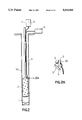
- FIG. 2 is a simplified vertical cross section of a first embodiment of an explosive device according to the invention received in a bore hole;
- FIG. 2A is a detail view of the region IIA of FIG. 2;
- FIG. 3 is a simplified vertical cross section of a second embodiment of a detonation system in accordance with the invention received in a bore hole;
- FIG. 4 is a simplified vertical cross section of a third embodiment of a detonation system in accordance with the invention received in a bore hole;
- FIG. 5 is a simplified vertical cross section of a fourth embodiment of a detonation system in accordance with the invention received in a bore hole;
- FIG. 6 is a simplified vertical cross section of a fifth embodiment of a detonation system in accordance with the invention received in a bore hole;
- FIG. 7 is a simplified vertical cross section of a sixth embodiment of a detonation system in accordance with the invention received in a bore hole;
- FIG. 2 shows a explosive device 2 positioned down a borehole 1, for example, of an off shore oil field.
- the explosive device 2 contains a requisite amount of explosive material 3 as in known detonation systems.
- an optical splitter 4 which is coupled to a fiber optic line 5, comprising an optical fiber, which is in turn coupled to a remotely located laser 6 (see FIG. 2A).
- the firing laser 6 provides an optical signal, i.e. a pulse of laser light which is carried along the fiber optic line 5 to the splitter 4.
- optical and “light” as used herein are deemed to include signals having frequencies in both visible and non-visible ranges as may be produced by a laser.
- the firing laser 6 is selected to provide a laser pulse having a pre-determined detonation frequency and power which is sufficient to detonate the explosive material and thus the explosive device 2.
- the splitter 4 is chosen to be transmissive to light of this pre-determined frequency and power, but reflective to light of other frequencies.
- the splitter 4 allows a light pulse of this pre-determined detonation frequency and power to be emitted by the first laser 6 to impinge on the explosive material 3 and cause detonation, but will reflect other light pulses of different frequencies and prevent them from impinging on the explosive material 3.
- a typical laser for firing is a Nd-Yag laser which operates at 1064 nanometers, although, it will be appreciated that other lasers could be used for firing which have different frequencies.
- a preferred output energy of the laser is in the range of 0.8 to 5 joules.
- the actual energy required to detonate the explosive device 2 can be as low as 10 milli Joules but the additional power is necessary to compensate for losses in energy during transmission along the fiber optic line 5.
- the laser used for firing the explosive device is required to be a pulse laser.
- the preferred fiber to be used is a silica fibre preferably hard coat silica.
- a typical size of line would be 200 microns in diameter which is necessary in order to avoid high energy densities which could damage interconnections.
- the fiber is preferably multi-mode fiber which is more tolerant of bends and couplings than is a single-mode fiber.
- the integrity of the fibre optic line 5 can be tested after it has been fitted but before detonation and without any risk of detonation, using a test signal.
- the testing signal is provided by a second remotely located laser 11.
- the second laser 11 is a lower powered laser, with a power of up to five orders of magnitude less than that of the first firing laser 6.
- the test signal is coupled to the fibre optic line 5 for transmitting down the fiber optic line 5.
- the test signal is selected to have any frequency other than that used for firing, i.e. the detonation frequency. such that such frequencies will be reflected by the reflector. Because the splitter 4 is chosen to transmit light at the detonation frequency and to reflect light at all, or most other frequencies, the test signal is reflected back along the fiber optic line 5 without reaching the explosive material 3.
- test signal sensor 9 which is also remotely located. Non-detection of the test signal would indicate a fault, for example a break, in the fiber optic line 5. Because the power of the test signal is selected to be less than the detonation signal, the risk of premature detonation is further reduced.
- the fiber optic line 5 can be coupled to the first and second lasers, the splitter 4 and the test sensor 9 by any known optical or mechanical coupling.
- the preferred coupling method is epoxy crimp coupling.
- FIG. 3 shows a second embodiment of the invention whereby the detonating system of FIG. 2 also incorporates a sensor 7 for monitoring external operating parameters.
- Conventional sensors are commonly used in boreholes for sensing pressure, temperature etc, in the surrounding area of the explosive device 2. It is essential to monitor these and other external parameters in order to effectively manage the production from an oil field and to plan the various required drilling operations.
- the sensor 7 is provided at a suitable location along the fiber optic fiber 5 as shown in FIG. 3.
- the sensor is of a known type used to monitor these commonly monitored parameters and is coupled to the fiber optic line 5 in any known manner. More than one of these fiber optic sensors 7 may be provided if required.
- Information from the sensor or sensors 7 is then relayed, for example using the fiber optic line 5 to a remotely located detector 9, for example a printer for use by the operator.
- a remotely located detector 9 for example a printer for use by the operator.
- the fiber optic sensor 7 is designed to withstand the arduous and uncertain conditions found down a borehole which would typically be up to 20,000 psi.
- the fiber optic sensor 7 or a number of such sensors can be coupled to the fiber optic line 5 thus considerably reducing the amount of separate cabling required in conventional systems.
- FIG. 4 shows a detonation system incorporating two explosive devices 2, which may be separated from each other by a large distance.
- the explosive devices 2 are coupled to the same fiber optic line 5 and are therefore detonated at the same time.
- Optical splitters (not shown) are provided in the fiber optic line 5 at the junctions where the fiber optic line 5 is to be coupled to the explosive devices 2 to direct the laser pulses to the explosive devices 2.
- FIG. 5 shows an embodiment in which the fiber optic line 5 is coupled to the explosive device 2 at a lower section rather than an upper section as in the previous embodiments.
- Many detonation systems have explosive devices which incorporate the use of a liquid which flows to the bottom of the explosive device in the event of a leak of other malfunction.
- the presence of the liquid at the bottom of the explosive device 2 can be detected by coupling the fiber optic line 5 to the bottom section of the explosive device 2.
- the explosive device can be disarmed in the vent of any malfunction. This is known as fluid desensitization.
- FIG. 6 shows an embodiment in which the fiber optic line 5 is coupled to the explosive device 2 at both upper and lower sections of the explosive device 2. This allows the explosive device to be detonated at two separate locations. Similarly optical splitters are used to couple the laser light to the two junctions. It may be advisable to use more than one way of detonating a particular explosive device, for example by using two or more separate lines. This is a precaution in case one or more of the lines failed or for some reason did not function. The explosive device can still be detonated by the remaining good line or lines. This is known as redundant firing.
- FIG. 7 shows an embodiment in which the fiber optic line 5 is provided with an intermediate laser 8 positioned at a certain point along the length of the fiber optic line 5.
- the intermediate laser 8 is triggered by light from the first firing laser 6 by means a photocell (not shown).
- the intermediate laser 8 further comprises a capacitor(not shown) and a discharge circuit.
- the photocell detects a signal from the firing laser 6, the firing laser 6 triggers the intermediate laser 8 to release power the capacitor to pump the intermediate laser 8 to release a further laser pulse to detonate the explosive device 2.
- the capacitor can be recharged as required by a continuous wave from the firing laser 6. It is advantageous to locate the intermediate laser 8 as close to the explosive device 2 as possible. This is particularly the case when there is a large distance between the surface laser and the explosive device because it will be necessary to take account of unpredictable losses of power occurring over large distances. More than one intermediate laser can be used.
- Shot detection may be achieved by two methods.
- the first is a direct method by detection of the flash which is emitted from the detonator after the initial light pulse is sent to detonate the explosion and is transmitted back up the fiber optic cable. With appropriate instrumentation this delayed signal can be measured and recorded at the surface as an indication of detonation. This method is suitable for both top and bottom detonation.
- Shot detection can also, be achieved indirectly whereby a signal can be sent down to the device to be detonated and which is reflected back if there is no detonation or not reflected back if there is a detonation.
- a signal can be sent down to the device to be detonated and which is reflected back if there is no detonation or not reflected back if there is a detonation.
- two or more reflectors which reflect light at different frequencies can be used to indicate where different parts of the system have detonated.
- a fibre optic sensor other than a reflector can be used with the sensors being read by a technique such as time division multiplexing.
- a device could be arranged which changes the reflector or sensor to a different type when the detonation is detected.
- FIG. 1 illustrates an embodiment of the detonation system 10 in accordance with the invention integrated with an off-shore oil platform 100.
- the firing laser 6 and associated electrical and electronic circuitry is contained in a firing station 12, remotely located on the oil platform 100, itself.
- the fiber optic line 5 is enclosed in tubing 30, and, as described above, is coupled to at least one sensor monitoring the external, environmental parameters of the oil well.
- the fiber optic line 5 is also coupled to the explosive device 2, also referred to as a perforating gun, located down the bore hole in the reservoir 14 of oil.
- the lower powered laser 11, the test signal sensor 9, the externally monitored parameter detector and associated circuitry are provided in a testing and monitoring station 15 also remotely located on the platform 100.
Abstract
Description
Claims (15)
Applications Claiming Priority (2)
| Application Number | Priority Date | Filing Date | Title |
|---|---|---|---|
| GB9219666 | 1992-09-17 | ||
| GB929219666A GB9219666D0 (en) | 1992-09-17 | 1992-09-17 | A detonating system |
Publications (1)
| Publication Number | Publication Date |
|---|---|
| US5413045A true US5413045A (en) | 1995-05-09 |
Family
ID=10722062
Family Applications (1)
| Application Number | Title | Priority Date | Filing Date |
|---|---|---|---|
| US08/116,883 Expired - Lifetime US5413045A (en) | 1992-09-17 | 1993-09-07 | Detonation system |
Country Status (2)
| Country | Link |
|---|---|
| US (1) | US5413045A (en) |
| GB (2) | GB9219666D0 (en) |
Cited By (58)
| Publication number | Priority date | Publication date | Assignee | Title |
|---|---|---|---|---|
| US5700968A (en) * | 1996-09-30 | 1997-12-23 | Blimke; Ross Arthur | Perforating gun brake |
| US6148263A (en) * | 1998-10-27 | 2000-11-14 | Schlumberger Technology Corporation | Activation of well tools |
| US6283227B1 (en) | 1998-10-27 | 2001-09-04 | Schlumberger Technology Corporation | Downhole activation system that assigns and retrieves identifiers |
| US6385031B1 (en) | 1998-09-24 | 2002-05-07 | Schlumberger Technology Corporation | Switches for use in tools |
| US6460460B1 (en) * | 2000-06-29 | 2002-10-08 | University Of Maryland | Laser-activated grenade with agile target effects |
| US20030000411A1 (en) * | 2001-06-29 | 2003-01-02 | Cernocky Edward Paul | Method and apparatus for detonating an explosive charge |
| WO2003002849A1 (en) * | 2001-06-29 | 2003-01-09 | Shell Internationale Research Maatschappij B.V. | Method and apparatus for detonating an explosive charge |
| US20040020645A1 (en) * | 2000-12-27 | 2004-02-05 | Baker Hughes Incorporated | Method and apparatus for a tubing conveyed perforating guns fire identification system using enhanced marker material |
| WO2004020790A2 (en) * | 2002-08-30 | 2004-03-11 | Sensor Highway Limited | Method and apparatus for logging a well using fiber optics |
| WO2004020774A2 (en) * | 2002-08-30 | 2004-03-11 | Sensor Highway Limited | Methods and systems to activate downhole tools with light |
| US6732656B1 (en) | 2002-09-16 | 2004-05-11 | The United States Of America As Represented By The Secretary Of The Air Force | High voltage tolerant explosive initiation |
| US6752083B1 (en) | 1998-09-24 | 2004-06-22 | Schlumberger Technology Corporation | Detonators for use with explosive devices |
| US20040206503A1 (en) * | 2003-01-09 | 2004-10-21 | Shell Oil Company | Casing conveyed well perforating apparatus and method |
| US6837310B2 (en) | 2002-12-03 | 2005-01-04 | Schlumberger Technology Corporation | Intelligent perforating well system and method |
| US20050045331A1 (en) * | 1998-10-27 | 2005-03-03 | Lerche Nolan C. | Secure activation of a downhole device |
| GB2406870A (en) * | 2002-12-03 | 2005-04-13 | Schlumberger Holdings | Intelligent well perforation system |
| US6938689B2 (en) | 1998-10-27 | 2005-09-06 | Schumberger Technology Corp. | Communicating with a tool |
| US20060102343A1 (en) * | 2004-11-12 | 2006-05-18 | Skinner Neal G | Drilling, perforating and formation analysis |
| US20100326659A1 (en) * | 2009-06-29 | 2010-12-30 | Schultz Roger L | Wellbore laser operations |
| CN102155199A (en) * | 2011-02-01 | 2011-08-17 | 西北大学 | Petroleum underground laser perforation well completion device |
| CN102155195A (en) * | 2011-02-01 | 2011-08-17 | 西北大学 | Multi-control-unit multi-beam laser perforation device in oil well |
| CN102155197A (en) * | 2011-02-01 | 2011-08-17 | 西北大学 | Multi-beam laser perforating device under petroleum well |
| US20120273269A1 (en) * | 2008-08-20 | 2012-11-01 | Rinzler Charles C | Long distance high power optical laser fiber break detection and continuity monitoring systems and methods |
| US8424617B2 (en) | 2008-08-20 | 2013-04-23 | Foro Energy Inc. | Methods and apparatus for delivering high power laser energy to a surface |
| US8571368B2 (en) | 2010-07-21 | 2013-10-29 | Foro Energy, Inc. | Optical fiber configurations for transmission of laser energy over great distances |
| US8627901B1 (en) | 2009-10-01 | 2014-01-14 | Foro Energy, Inc. | Laser bottom hole assembly |
| US8662160B2 (en) | 2008-08-20 | 2014-03-04 | Foro Energy Inc. | Systems and conveyance structures for high power long distance laser transmission |
| US8684088B2 (en) | 2011-02-24 | 2014-04-01 | Foro Energy, Inc. | Shear laser module and method of retrofitting and use |
| US8720584B2 (en) | 2011-02-24 | 2014-05-13 | Foro Energy, Inc. | Laser assisted system for controlling deep water drilling emergency situations |
| US8783361B2 (en) | 2011-02-24 | 2014-07-22 | Foro Energy, Inc. | Laser assisted blowout preventer and methods of use |
| US8783360B2 (en) | 2011-02-24 | 2014-07-22 | Foro Energy, Inc. | Laser assisted riser disconnect and method of use |
| US9027668B2 (en) | 2008-08-20 | 2015-05-12 | Foro Energy, Inc. | Control system for high power laser drilling workover and completion unit |
| US9074422B2 (en) | 2011-02-24 | 2015-07-07 | Foro Energy, Inc. | Electric motor for laser-mechanical drilling |
| US9080425B2 (en) | 2008-10-17 | 2015-07-14 | Foro Energy, Inc. | High power laser photo-conversion assemblies, apparatuses and methods of use |
| US9089928B2 (en) | 2008-08-20 | 2015-07-28 | Foro Energy, Inc. | Laser systems and methods for the removal of structures |
| US9138786B2 (en) | 2008-10-17 | 2015-09-22 | Foro Energy, Inc. | High power laser pipeline tool and methods of use |
| US9244235B2 (en) | 2008-10-17 | 2016-01-26 | Foro Energy, Inc. | Systems and assemblies for transferring high power laser energy through a rotating junction |
| US9242309B2 (en) | 2012-03-01 | 2016-01-26 | Foro Energy Inc. | Total internal reflection laser tools and methods |
| US20160032654A1 (en) * | 2013-08-27 | 2016-02-04 | Halliburton Energy Services, Inc. | Encapsulated explosives for drilling wellbores |
| US9329011B1 (en) | 2001-02-28 | 2016-05-03 | Orbital Atk, Inc. | High voltage arm/fire device and method |
| US9347271B2 (en) | 2008-10-17 | 2016-05-24 | Foro Energy, Inc. | Optical fiber cable for transmission of high power laser energy over great distances |
| US9360631B2 (en) | 2008-08-20 | 2016-06-07 | Foro Energy, Inc. | Optics assembly for high power laser tools |
| US9360643B2 (en) | 2011-06-03 | 2016-06-07 | Foro Energy, Inc. | Rugged passively cooled high power laser fiber optic connectors and methods of use |
| EP2948626A4 (en) * | 2013-01-24 | 2016-09-07 | Halliburton Energy Services Inc | Downhole optical acoustic transducers |
| US9464508B2 (en) | 1998-10-27 | 2016-10-11 | Schlumberger Technology Corporation | Interactive and/or secure activation of a tool |
| US9562395B2 (en) | 2008-08-20 | 2017-02-07 | Foro Energy, Inc. | High power laser-mechanical drilling bit and methods of use |
| US9664012B2 (en) | 2008-08-20 | 2017-05-30 | Foro Energy, Inc. | High power laser decomissioning of multistring and damaged wells |
| US9669492B2 (en) | 2008-08-20 | 2017-06-06 | Foro Energy, Inc. | High power laser offshore decommissioning tool, system and methods of use |
| US9719302B2 (en) | 2008-08-20 | 2017-08-01 | Foro Energy, Inc. | High power laser perforating and laser fracturing tools and methods of use |
| US9845652B2 (en) | 2011-02-24 | 2017-12-19 | Foro Energy, Inc. | Reduced mechanical energy well control systems and methods of use |
| US10221687B2 (en) | 2015-11-26 | 2019-03-05 | Merger Mines Corporation | Method of mining using a laser |
| US10294777B2 (en) | 2015-07-27 | 2019-05-21 | Cudd Pressure Control, Inc. | Steering tool system |
| US10301912B2 (en) * | 2008-08-20 | 2019-05-28 | Foro Energy, Inc. | High power laser flow assurance systems, tools and methods |
| CN111707152A (en) * | 2020-06-29 | 2020-09-25 | 南京邮电大学 | Multipoint blasting system based on optical fiber energy supply and working method |
| US10941637B2 (en) | 2015-06-26 | 2021-03-09 | Halliburton Energy Services, Inc. | Laser firing head for perforating gun |
| RU2752408C1 (en) * | 2020-08-05 | 2021-07-27 | Российская Федерация, от имени которой выступает Государственная корпорация по атомной энергии "Росатом" (Госкорпорация "Росатом") | Method for initiating multi-channel laser initiation system |
| US11473410B1 (en) | 2021-09-28 | 2022-10-18 | Saudi Arabian Oil Company | Hybrid perforation tool and methods |
| RU2807949C1 (en) * | 2022-02-28 | 2023-11-21 | Публичное акционерное общество "Пермская научно-производственная приборостроительная компания" | Method and device for checking the integrity of optical and electrical circuits in laser initiation systems for energy materials |
Families Citing this family (2)
| Publication number | Priority date | Publication date | Assignee | Title |
|---|---|---|---|---|
| WO1997009581A2 (en) * | 1995-08-25 | 1997-03-13 | Oleg Mikhailovich Denisov | Method and device for carrying out blasting operations |
| PE20060926A1 (en) | 2004-11-02 | 2006-09-04 | Orica Explosives Tech Pty Ltd | ASSEMBLIES OF WIRELESS DETONATORS, CORRESPONDING BLASTING APPLIANCES AND BLASTING METHODS |
Citations (8)
| Publication number | Priority date | Publication date | Assignee | Title |
|---|---|---|---|---|
| US3812783A (en) * | 1972-08-03 | 1974-05-28 | Nasa | Optically detonated explosive device |
| US4391195A (en) * | 1979-08-21 | 1983-07-05 | Shann Peter C | Detonation of explosive charges and equipment therefor |
| WO1988007170A1 (en) * | 1987-03-17 | 1988-09-22 | Arthur George Yarrington | Optic detonator coupled to a remote optic triggering means |
| US4860654A (en) * | 1985-05-22 | 1989-08-29 | Western Atlas International, Inc. | Implosion shaped charge perforator |
| US4862802A (en) * | 1988-07-11 | 1989-09-05 | Spectra Diode Laboratories, Inc. | Method of initiating a sequence of pyrotechnic events |
| US4917014A (en) * | 1989-04-24 | 1990-04-17 | Kms Fusion, Inc. | Laser ignition of explosives |
| US5001981A (en) * | 1990-04-16 | 1991-03-26 | The Ensign-Bickford Company | Signal transmission tube for initiation of explosives |
| US5138946A (en) * | 1991-06-21 | 1992-08-18 | Mcdonnell Douglas Corporation | Laser diode apparatus for initiation of explosive devices |
-
1992
- 1992-09-17 GB GB929219666A patent/GB9219666D0/en active Pending
-
1993
- 1993-09-06 GB GB9318450A patent/GB2270743B/en not_active Expired - Fee Related
- 1993-09-07 US US08/116,883 patent/US5413045A/en not_active Expired - Lifetime
Patent Citations (8)
| Publication number | Priority date | Publication date | Assignee | Title |
|---|---|---|---|---|
| US3812783A (en) * | 1972-08-03 | 1974-05-28 | Nasa | Optically detonated explosive device |
| US4391195A (en) * | 1979-08-21 | 1983-07-05 | Shann Peter C | Detonation of explosive charges and equipment therefor |
| US4860654A (en) * | 1985-05-22 | 1989-08-29 | Western Atlas International, Inc. | Implosion shaped charge perforator |
| WO1988007170A1 (en) * | 1987-03-17 | 1988-09-22 | Arthur George Yarrington | Optic detonator coupled to a remote optic triggering means |
| US4862802A (en) * | 1988-07-11 | 1989-09-05 | Spectra Diode Laboratories, Inc. | Method of initiating a sequence of pyrotechnic events |
| US4917014A (en) * | 1989-04-24 | 1990-04-17 | Kms Fusion, Inc. | Laser ignition of explosives |
| US5001981A (en) * | 1990-04-16 | 1991-03-26 | The Ensign-Bickford Company | Signal transmission tube for initiation of explosives |
| US5138946A (en) * | 1991-06-21 | 1992-08-18 | Mcdonnell Douglas Corporation | Laser diode apparatus for initiation of explosive devices |
Cited By (111)
| Publication number | Priority date | Publication date | Assignee | Title |
|---|---|---|---|---|
| US5700968A (en) * | 1996-09-30 | 1997-12-23 | Blimke; Ross Arthur | Perforating gun brake |
| US6386108B1 (en) | 1998-09-24 | 2002-05-14 | Schlumberger Technology Corp | Initiation of explosive devices |
| US6752083B1 (en) | 1998-09-24 | 2004-06-22 | Schlumberger Technology Corporation | Detonators for use with explosive devices |
| US6385031B1 (en) | 1998-09-24 | 2002-05-07 | Schlumberger Technology Corporation | Switches for use in tools |
| US6604584B2 (en) | 1998-10-27 | 2003-08-12 | Schlumberger Technology Corporation | Downhole activation system |
| US9464508B2 (en) | 1998-10-27 | 2016-10-11 | Schlumberger Technology Corporation | Interactive and/or secure activation of a tool |
| US6148263A (en) * | 1998-10-27 | 2000-11-14 | Schlumberger Technology Corporation | Activation of well tools |
| US6283227B1 (en) | 1998-10-27 | 2001-09-04 | Schlumberger Technology Corporation | Downhole activation system that assigns and retrieves identifiers |
| US20050045331A1 (en) * | 1998-10-27 | 2005-03-03 | Lerche Nolan C. | Secure activation of a downhole device |
| US6938689B2 (en) | 1998-10-27 | 2005-09-06 | Schumberger Technology Corp. | Communicating with a tool |
| US7347278B2 (en) | 1998-10-27 | 2008-03-25 | Schlumberger Technology Corporation | Secure activation of a downhole device |
| US6460460B1 (en) * | 2000-06-29 | 2002-10-08 | University Of Maryland | Laser-activated grenade with agile target effects |
| US20060054317A1 (en) * | 2000-12-27 | 2006-03-16 | Baker Hughes Incorporated | Method and apparatus for a tubing conveyed perforating guns fire identification system using fiber optics |
| US6955217B2 (en) * | 2000-12-27 | 2005-10-18 | Baker Hughes Incorporated | Method and apparatus for a tubing conveyed perforating guns fire identification system using fiber optics |
| US20040020645A1 (en) * | 2000-12-27 | 2004-02-05 | Baker Hughes Incorporated | Method and apparatus for a tubing conveyed perforating guns fire identification system using enhanced marker material |
| US9329011B1 (en) | 2001-02-28 | 2016-05-03 | Orbital Atk, Inc. | High voltage arm/fire device and method |
| WO2003002849A1 (en) * | 2001-06-29 | 2003-01-09 | Shell Internationale Research Maatschappij B.V. | Method and apparatus for detonating an explosive charge |
| US20030000411A1 (en) * | 2001-06-29 | 2003-01-02 | Cernocky Edward Paul | Method and apparatus for detonating an explosive charge |
| GB2409479A (en) * | 2002-08-30 | 2005-06-29 | Sensor Highway Ltd | Methods and systems to activate downhole tools with light |
| US7854267B2 (en) | 2002-08-30 | 2010-12-21 | Schlumberger Technology Corporation | Methods and systems to activate downhole tools with light |
| GB2426024A (en) * | 2002-08-30 | 2006-11-15 | Sensor Highway Ltd | Activation of downhole tools with light |
| WO2004020774A3 (en) * | 2002-08-30 | 2004-04-22 | Sensor Highway Ltd | Methods and systems to activate downhole tools with light |
| WO2004020790A3 (en) * | 2002-08-30 | 2004-04-22 | Sensor Highway Ltd | Method and apparatus for logging a well using fiber optics |
| US20100025032A1 (en) * | 2002-08-30 | 2010-02-04 | Schlumberger Technology Corporation | Methods and systems to activate downhole tools with light |
| WO2004020774A2 (en) * | 2002-08-30 | 2004-03-11 | Sensor Highway Limited | Methods and systems to activate downhole tools with light |
| WO2004020790A2 (en) * | 2002-08-30 | 2004-03-11 | Sensor Highway Limited | Method and apparatus for logging a well using fiber optics |
| GB2426024B (en) * | 2002-08-30 | 2007-05-30 | Sensor Highway Ltd | Methods and systems for perforating wells |
| US20070044672A1 (en) * | 2002-08-30 | 2007-03-01 | Smith David R | Methods and systems to activate downhole tools with light |
| US20060102347A1 (en) * | 2002-08-30 | 2006-05-18 | Smith David R | Method and apparatus for logging a well using fiber optics |
| GB2409479B (en) * | 2002-08-30 | 2006-12-06 | Sensor Highway Ltd | Methods and systems to activate downhole tools with light |
| US6732656B1 (en) | 2002-09-16 | 2004-05-11 | The United States Of America As Represented By The Secretary Of The Air Force | High voltage tolerant explosive initiation |
| US6837310B2 (en) | 2002-12-03 | 2005-01-04 | Schlumberger Technology Corporation | Intelligent perforating well system and method |
| GB2406870B (en) * | 2002-12-03 | 2006-04-12 | Schlumberger Holdings | Intelligent well perforating systems and methods |
| GB2406870A (en) * | 2002-12-03 | 2005-04-13 | Schlumberger Holdings | Intelligent well perforation system |
| US7461580B2 (en) | 2003-01-09 | 2008-12-09 | Shell Oil Company | Casing conveyed well perforating apparatus and method |
| US7284601B2 (en) | 2003-01-09 | 2007-10-23 | Shell Oil Company | Casing conveyed well perforating apparatus and method |
| US7284489B2 (en) | 2003-01-09 | 2007-10-23 | Shell Oil Company | Casing conveyed well perforating apparatus and method |
| US20060060355A1 (en) * | 2003-01-09 | 2006-03-23 | Bell Matthew R G | Perforating apparatus, firing assembly, and method |
| US20060196693A1 (en) * | 2003-01-09 | 2006-09-07 | Bell Matthew R G | Perforating apparatus, firing assembly, and method |
| US20060000613A1 (en) * | 2003-01-09 | 2006-01-05 | Bell Matthew R G | Casing conveyed well perforating apparatus and method |
| US20050121195A1 (en) * | 2003-01-09 | 2005-06-09 | Bell Matthew R.G. | Casing conveyed well perforating apparatus and method |
| US20040206503A1 (en) * | 2003-01-09 | 2004-10-21 | Shell Oil Company | Casing conveyed well perforating apparatus and method |
| US7975592B2 (en) | 2003-01-09 | 2011-07-12 | Shell Oil Company | Perforating apparatus, firing assembly, and method |
| US7490664B2 (en) | 2004-11-12 | 2009-02-17 | Halliburton Energy Services, Inc. | Drilling, perforating and formation analysis |
| US20090133871A1 (en) * | 2004-11-12 | 2009-05-28 | Skinner Neal G | Drilling, perforating and formation analysis |
| US7938175B2 (en) | 2004-11-12 | 2011-05-10 | Halliburton Energy Services Inc. | Drilling, perforating and formation analysis |
| US20060102343A1 (en) * | 2004-11-12 | 2006-05-18 | Skinner Neal G | Drilling, perforating and formation analysis |
| US8424617B2 (en) | 2008-08-20 | 2013-04-23 | Foro Energy Inc. | Methods and apparatus for delivering high power laser energy to a surface |
| US9284783B1 (en) | 2008-08-20 | 2016-03-15 | Foro Energy, Inc. | High power laser energy distribution patterns, apparatus and methods for creating wells |
| US20120273269A1 (en) * | 2008-08-20 | 2012-11-01 | Rinzler Charles C | Long distance high power optical laser fiber break detection and continuity monitoring systems and methods |
| US10036232B2 (en) | 2008-08-20 | 2018-07-31 | Foro Energy | Systems and conveyance structures for high power long distance laser transmission |
| US9669492B2 (en) | 2008-08-20 | 2017-06-06 | Foro Energy, Inc. | High power laser offshore decommissioning tool, system and methods of use |
| US9664012B2 (en) | 2008-08-20 | 2017-05-30 | Foro Energy, Inc. | High power laser decomissioning of multistring and damaged wells |
| US9562395B2 (en) | 2008-08-20 | 2017-02-07 | Foro Energy, Inc. | High power laser-mechanical drilling bit and methods of use |
| US10301912B2 (en) * | 2008-08-20 | 2019-05-28 | Foro Energy, Inc. | High power laser flow assurance systems, tools and methods |
| US8511401B2 (en) | 2008-08-20 | 2013-08-20 | Foro Energy, Inc. | Method and apparatus for delivering high power laser energy over long distances |
| US9360631B2 (en) | 2008-08-20 | 2016-06-07 | Foro Energy, Inc. | Optics assembly for high power laser tools |
| US8826973B2 (en) | 2008-08-20 | 2014-09-09 | Foro Energy, Inc. | Method and system for advancement of a borehole using a high power laser |
| US9719302B2 (en) | 2008-08-20 | 2017-08-01 | Foro Energy, Inc. | High power laser perforating and laser fracturing tools and methods of use |
| US9267330B2 (en) * | 2008-08-20 | 2016-02-23 | Foro Energy, Inc. | Long distance high power optical laser fiber break detection and continuity monitoring systems and methods |
| US11060378B2 (en) * | 2008-08-20 | 2021-07-13 | Foro Energy, Inc. | High power laser flow assurance systems, tools and methods |
| US8636085B2 (en) | 2008-08-20 | 2014-01-28 | Foro Energy, Inc. | Methods and apparatus for removal and control of material in laser drilling of a borehole |
| US8662160B2 (en) | 2008-08-20 | 2014-03-04 | Foro Energy Inc. | Systems and conveyance structures for high power long distance laser transmission |
| US9089928B2 (en) | 2008-08-20 | 2015-07-28 | Foro Energy, Inc. | Laser systems and methods for the removal of structures |
| US9027668B2 (en) | 2008-08-20 | 2015-05-12 | Foro Energy, Inc. | Control system for high power laser drilling workover and completion unit |
| US8701794B2 (en) | 2008-08-20 | 2014-04-22 | Foro Energy, Inc. | High power laser perforating tools and systems |
| US8997894B2 (en) | 2008-08-20 | 2015-04-07 | Foro Energy, Inc. | Method and apparatus for delivering high power laser energy over long distances |
| US8757292B2 (en) | 2008-08-20 | 2014-06-24 | Foro Energy, Inc. | Methods for enhancing the efficiency of creating a borehole using high power laser systems |
| US8936108B2 (en) | 2008-08-20 | 2015-01-20 | Foro Energy, Inc. | High power laser downhole cutting tools and systems |
| US8869914B2 (en) | 2008-08-20 | 2014-10-28 | Foro Energy, Inc. | High power laser workover and completion tools and systems |
| US8820434B2 (en) | 2008-08-20 | 2014-09-02 | Foro Energy, Inc. | Apparatus for advancing a wellbore using high power laser energy |
| US9244235B2 (en) | 2008-10-17 | 2016-01-26 | Foro Energy, Inc. | Systems and assemblies for transferring high power laser energy through a rotating junction |
| US9347271B2 (en) | 2008-10-17 | 2016-05-24 | Foro Energy, Inc. | Optical fiber cable for transmission of high power laser energy over great distances |
| US9327810B2 (en) | 2008-10-17 | 2016-05-03 | Foro Energy, Inc. | High power laser ROV systems and methods for treating subsea structures |
| US9080425B2 (en) | 2008-10-17 | 2015-07-14 | Foro Energy, Inc. | High power laser photo-conversion assemblies, apparatuses and methods of use |
| US9138786B2 (en) | 2008-10-17 | 2015-09-22 | Foro Energy, Inc. | High power laser pipeline tool and methods of use |
| US8540026B2 (en) | 2009-06-29 | 2013-09-24 | Halliburton Energy Services, Inc. | Wellbore laser operations |
| US20100326659A1 (en) * | 2009-06-29 | 2010-12-30 | Schultz Roger L | Wellbore laser operations |
| US8464794B2 (en) | 2009-06-29 | 2013-06-18 | Halliburton Energy Services, Inc. | Wellbore laser operations |
| US8528643B2 (en) | 2009-06-29 | 2013-09-10 | Halliburton Energy Services, Inc. | Wellbore laser operations |
| US8678087B2 (en) | 2009-06-29 | 2014-03-25 | Halliburton Energy Services, Inc. | Wellbore laser operations |
| US8534357B2 (en) | 2009-06-29 | 2013-09-17 | Halliburton Energy Services, Inc. | Wellbore laser operations |
| US8627901B1 (en) | 2009-10-01 | 2014-01-14 | Foro Energy, Inc. | Laser bottom hole assembly |
| US8571368B2 (en) | 2010-07-21 | 2013-10-29 | Foro Energy, Inc. | Optical fiber configurations for transmission of laser energy over great distances |
| US8879876B2 (en) | 2010-07-21 | 2014-11-04 | Foro Energy, Inc. | Optical fiber configurations for transmission of laser energy over great distances |
| CN102155195B (en) * | 2011-02-01 | 2013-06-12 | 西北大学 | Multi-control-unit multi-beam laser perforation device in oil well |
| CN102155199A (en) * | 2011-02-01 | 2011-08-17 | 西北大学 | Petroleum underground laser perforation well completion device |
| CN102155195A (en) * | 2011-02-01 | 2011-08-17 | 西北大学 | Multi-control-unit multi-beam laser perforation device in oil well |
| CN102155197A (en) * | 2011-02-01 | 2011-08-17 | 西北大学 | Multi-beam laser perforating device under petroleum well |
| CN102155199B (en) * | 2011-02-01 | 2013-06-12 | 西北大学 | Petroleum underground laser perforation well completion device |
| CN102155197B (en) * | 2011-02-01 | 2013-06-12 | 西北大学 | Multi-beam laser perforating device under petroleum well |
| US8720584B2 (en) | 2011-02-24 | 2014-05-13 | Foro Energy, Inc. | Laser assisted system for controlling deep water drilling emergency situations |
| US8783360B2 (en) | 2011-02-24 | 2014-07-22 | Foro Energy, Inc. | Laser assisted riser disconnect and method of use |
| US8783361B2 (en) | 2011-02-24 | 2014-07-22 | Foro Energy, Inc. | Laser assisted blowout preventer and methods of use |
| US9291017B2 (en) | 2011-02-24 | 2016-03-22 | Foro Energy, Inc. | Laser assisted system for controlling deep water drilling emergency situations |
| US9845652B2 (en) | 2011-02-24 | 2017-12-19 | Foro Energy, Inc. | Reduced mechanical energy well control systems and methods of use |
| US8684088B2 (en) | 2011-02-24 | 2014-04-01 | Foro Energy, Inc. | Shear laser module and method of retrofitting and use |
| US9074422B2 (en) | 2011-02-24 | 2015-07-07 | Foro Energy, Inc. | Electric motor for laser-mechanical drilling |
| US9784037B2 (en) | 2011-02-24 | 2017-10-10 | Daryl L. Grubb | Electric motor for laser-mechanical drilling |
| US9360643B2 (en) | 2011-06-03 | 2016-06-07 | Foro Energy, Inc. | Rugged passively cooled high power laser fiber optic connectors and methods of use |
| US9242309B2 (en) | 2012-03-01 | 2016-01-26 | Foro Energy Inc. | Total internal reflection laser tools and methods |
| EP2948626A4 (en) * | 2013-01-24 | 2016-09-07 | Halliburton Energy Services Inc | Downhole optical acoustic transducers |
| US20160032654A1 (en) * | 2013-08-27 | 2016-02-04 | Halliburton Energy Services, Inc. | Encapsulated explosives for drilling wellbores |
| US10941637B2 (en) | 2015-06-26 | 2021-03-09 | Halliburton Energy Services, Inc. | Laser firing head for perforating gun |
| US10294777B2 (en) | 2015-07-27 | 2019-05-21 | Cudd Pressure Control, Inc. | Steering tool system |
| US10221687B2 (en) | 2015-11-26 | 2019-03-05 | Merger Mines Corporation | Method of mining using a laser |
| CN111707152A (en) * | 2020-06-29 | 2020-09-25 | 南京邮电大学 | Multipoint blasting system based on optical fiber energy supply and working method |
| CN111707152B (en) * | 2020-06-29 | 2022-07-01 | 南京邮电大学 | Multipoint blasting system based on optical fiber energy supply and working method |
| RU2752408C1 (en) * | 2020-08-05 | 2021-07-27 | Российская Федерация, от имени которой выступает Государственная корпорация по атомной энергии "Росатом" (Госкорпорация "Росатом") | Method for initiating multi-channel laser initiation system |
| US11473410B1 (en) | 2021-09-28 | 2022-10-18 | Saudi Arabian Oil Company | Hybrid perforation tool and methods |
| RU2807949C1 (en) * | 2022-02-28 | 2023-11-21 | Публичное акционерное общество "Пермская научно-производственная приборостроительная компания" | Method and device for checking the integrity of optical and electrical circuits in laser initiation systems for energy materials |
Also Published As
| Publication number | Publication date |
|---|---|
| GB9318450D0 (en) | 1993-10-20 |
| GB2270743B (en) | 1996-05-08 |
| GB2270743A (en) | 1994-03-23 |
| GB9219666D0 (en) | 1992-10-28 |
Similar Documents
| Publication | Publication Date | Title |
|---|---|---|
| US5413045A (en) | Detonation system | |
| US4648471A (en) | Control system for borehole tools | |
| US7487833B2 (en) | Safety apparatus for perforating system | |
| CA2853815C (en) | Novel device and methods for firing perforating guns | |
| US5322019A (en) | System for the initiation of downhole explosive and propellant systems | |
| US8789467B2 (en) | Surface safe explosive tool | |
| US5159146A (en) | Methods and apparatus for selectively arming well bore explosive tools | |
| US5165489A (en) | Safety device to prevent premature firing of explosive well tools | |
| EP0471622B1 (en) | Transfer apparatus adapted for transferring an explosive train through an externally pressurized secondary explosive bulkhead | |
| CA2451822C (en) | Intelligent perforating well system and method | |
| US4700629A (en) | Optically-energized, emp-resistant, fast-acting, explosion initiating device | |
| US5369579A (en) | Electronic blast control system for downhole well operations | |
| US11408278B2 (en) | Autonomous tool | |
| US10490054B2 (en) | In-line integrity checker | |
| US20100230105A1 (en) | Perforating with wired drill pipe | |
| CA2714785A1 (en) | Novel device and methods for firing perforating guns | |
| US4656944A (en) | Select fire well perforator system and method of operation | |
| GB2284626A (en) | Monitoring subsurface formations | |
| GB2406870A (en) | Intelligent well perforation system | |
| US20100265063A1 (en) | Blasting device | |
| NO309690B1 (en) | Detonator type exploding wire for use with a perforation tool in a well | |
| US20230349677A1 (en) | Focused output detonator | |
| US4561356A (en) | Explosive charge safe-arming system | |
| Fletcher¹ et al. | Reducing Accidents through Improved Blasting Safety | |
| Koczan et al. | Drill-pipe severing tool with high-temperature explosive |
Legal Events
| Date | Code | Title | Description |
|---|---|---|---|
| STCF | Information on status: patent grant |
Free format text: PATENTED CASE |
|
| FEPP | Fee payment procedure |
Free format text: PAT HLDR NO LONGER CLAIMS SMALL ENT STAT AS INDIV INVENTOR (ORIGINAL EVENT CODE: LSM1); ENTITY STATUS OF PATENT OWNER: SMALL ENTITY |
|
| FPAY | Fee payment |
Year of fee payment: 4 |
|
| FEPP | Fee payment procedure |
Free format text: PAT HOLDER CLAIMS SMALL ENTITY STATUS, ENTITY STATUS SET TO SMALL (ORIGINAL EVENT CODE: LTOS); ENTITY STATUS OF PATENT OWNER: SMALL ENTITY Free format text: PAYOR NUMBER ASSIGNED (ORIGINAL EVENT CODE: ASPN); ENTITY STATUS OF PATENT OWNER: SMALL ENTITY |
|
| FPAY | Fee payment |
Year of fee payment: 8 |
|
| FPAY | Fee payment |
Year of fee payment: 12 |