US5415038A - Hand-held sensing instrument - Google Patents

Hand-held sensing instrument Download PDF

Info

Publication number
US5415038A
US5415038A US07/923,376 US92337692A US5415038A US 5415038 A US5415038 A US 5415038A US 92337692 A US92337692 A US 92337692A US 5415038 A US5415038 A US 5415038A
Authority
US
United States
Prior art keywords
instrument
hand
held
front wall
housing blank
Prior art date
Legal status (The legal status is an assumption and is not a legal conclusion. Google has not performed a legal analysis and makes no representation as to the accuracy of the status listed.)
Expired - Lifetime
Application number
US07/923,376
Inventor
Alan Rynhart
Brendan Farrell
Sean Fallon
Current Assignee (The listed assignees may be inaccurate. Google has not performed a legal analysis and makes no representation or warranty as to the accuracy of the list.)
RYNHART RESEARCH Ltd
Original Assignee
Rynhart Res Ltd
Priority date (The priority date is an assumption and is not a legal conclusion. Google has not performed a legal analysis and makes no representation as to the accuracy of the date listed.)
Filing date
Publication date
Application filed by Rynhart Res Ltd filed Critical Rynhart Res Ltd
Assigned to RYNHART RESEARCH LIMITED reassignment RYNHART RESEARCH LIMITED ASSIGNMENT OF ASSIGNORS INTEREST. Assignors: FALLON, SEAN, FARRELL, BRENDAN, RYNHART, ALAN
Application granted granted Critical
Publication of US5415038A publication Critical patent/US5415038A/en
Anticipated expiration legal-status Critical
Expired - Lifetime legal-status Critical Current

Links

Images

Classifications

    • HELECTRICITY
    • H05ELECTRIC TECHNIQUES NOT OTHERWISE PROVIDED FOR
    • H05KPRINTED CIRCUITS; CASINGS OR CONSTRUCTIONAL DETAILS OF ELECTRIC APPARATUS; MANUFACTURE OF ASSEMBLAGES OF ELECTRICAL COMPONENTS
    • H05K5/00Casings, cabinets or drawers for electric apparatus
    • H05K5/04Metal casings
    • GPHYSICS
    • G01MEASURING; TESTING
    • G01DMEASURING NOT SPECIALLY ADAPTED FOR A SPECIFIC VARIABLE; ARRANGEMENTS FOR MEASURING TWO OR MORE VARIABLES NOT COVERED IN A SINGLE OTHER SUBCLASS; TARIFF METERING APPARATUS; MEASURING OR TESTING NOT OTHERWISE PROVIDED FOR
    • G01D11/00Component parts of measuring arrangements not specially adapted for a specific variable
    • G01D11/24Housings ; Casings for instruments
    • YGENERAL TAGGING OF NEW TECHNOLOGICAL DEVELOPMENTS; GENERAL TAGGING OF CROSS-SECTIONAL TECHNOLOGIES SPANNING OVER SEVERAL SECTIONS OF THE IPC; TECHNICAL SUBJECTS COVERED BY FORMER USPC CROSS-REFERENCE ART COLLECTIONS [XRACs] AND DIGESTS
    • Y10TECHNICAL SUBJECTS COVERED BY FORMER USPC
    • Y10TTECHNICAL SUBJECTS COVERED BY FORMER US CLASSIFICATION
    • Y10T29/00Metal working
    • Y10T29/53Means to assemble or disassemble
    • Y10T29/5313Means to assemble electrical device

Definitions

  • the invention relates to hand-held instruments and to their production.
  • examples of such instruments include moisture meters, thermometers, pH meters, and humidity meters.
  • a further problem with presently available hand-held instruments is that the housing or casing may be relatively easily distorted. This can cause considerable problems for instruments such as moisture meters where it is essential that the support for sensors such as capacitive pads remain rigid.
  • the invention is directed towards providing a method of producing a hand-held instrument which is more efficient and less costly than heretofore. Another object is that the production method be versatile for production of different instruments. A still further object of the invention is to provide a hand-held instrument which is of high strength and thus not susceptible to distortion.
  • a hand-held instrument comprising the steps of:
  • a housing blank which is channel-shaped in cross-section, having a base for forming an instrument front wall, and a pair of side walls;
  • the invention provides a hand-held instrument comprising:
  • housing blank which is channel-shaped in cross-section, having a base which forms an instrument front wall, and a pair of side walls, the front wall having apertures;
  • the invention provides a housing blank for production of a hand-held instrument, the blank being channel-shaped in cross-section and having a base for forming an instrument front wall, and a pair of side walls, the front walls having apertures.
  • FIG. 1 is a front view of a hand-held instrument of the invention, in this case a moisture meter;
  • FIG. 2 is a perspective view showing the rear side of the meter
  • FIG. 3 is a side view of an alternative construction of moisture meter
  • FIG. 4 is a perspective view of housing blanks during a production process of the invention.
  • FIGS. 5 and 6 are exploded views showing assembly of a meter
  • FIGS. 7 and 8 are cross-sectional views in the direction of the arrows VII--VII of FIG. 6.
  • the meter 1 comprises a housing blank 2 of channel-shaped construction.
  • the housing blank has a base which forms a front wall 3 to which a label 4 is adhered.
  • End caps 5 are secured to each end of the blank 2 by self-tapping screws 5(a) and 5(b).
  • the back of the meter 1 comprises a backing plate 7 to which are secured a pair of electrode pads 8 for capacitive moisture detection.
  • the label 4 which is adhered to the front wall 3 is of flexible plastics material and includes a transparent portion 9 which is aligned with an aperture, not shown in FIGS. 1 and 2, having a similar shape in the front wall 3 to form a window for the instrument.
  • the label 4 has a cut-out aperture 10 to allow access to switches 11 connected to a circuit within the meter 1. Apertures 12 in the front wall 3 are shown by interrupted lines and these are covered by the label 4. Switches within the meter 1 may be operated using the label 4 because of its flexibility.
  • FIG. 3 there is shown an alternative construction of moisture meter indicated by the reference numeral 13 in which parts similar to those described with reference to FIGS. 1 and 2 are identified by the same reference numerals.
  • an end cap 14 which carries sensor pins 15 and a strap 16 for the meter.
  • the strap 16 passes through holes in a cover 17 for the pins 15 so that it may be slid on and off the pins 15, when desired, without falling from the meter 13.
  • the meter does not have electrode pads 8, however, it is possible that the backing plate 7 would have electrode pads 8 to improve versatility of use of the instrument.
  • the front wall 3 has a shallow longitudinal channel 18 for reception of the sliding switches 11.
  • a display aperture 19 for alignment with the window 9 in the label 4 is shown, as are the apertures 12.
  • the side walls 6 have inwardly-directed longitudinal strengthening ribs 20 which form a pair of opposed inner grooves.
  • the ribs 20 have curved inner surfaces to form a bearing surface for reception of the self-tapping screws 5(a) and 5(b).
  • the side walls 6 also include longitudinal strengthening ribs 21 which form a pair of opposed outer grooves.
  • Production of the moisture meters involves initially extruding aluminium lengths having the cross-section shown in FIG. 4. A length is then cut to individual blanks which are of the correct size for production of a particular moisture meter. In this embodiment all moisture meters within a range of different meters have the same length.
  • the apertures 10, 12 and 19 are stamped in the front wall 3. It has been found that because the housing blank 2 is of channel-shaped construction, tooling for stamping of the front wall 3 is relatively simple as it may easily access the rear of the front wall 3 for support during the stamping operation. Thus, stamping is considerably less expensive than would be the case, for example, if the housing blank were of tubular cross-section. For each of the different types of meters the same stamping tool is used because redundant apertures are simply covered over by the label.
  • a moisture meter circuit 22 is inserted into the housing blank 2 by sliding it into the pair of opposed inner grooves 20 until it is in correct alignment with the apertures in the front wall 3.
  • the switches 23 are aligned with the apertures 12 and the indicator 24 is aligned with the aperture 19.
  • the moisture meter which is being produced in this embodiment is not exactly similar to that shown in FIG. 1.
  • the backing plate 7 is then inserted by simply sliding it in the grooves 21.
  • both the circuit 22 and the backing plate 7 are held in position and are flush with the ends of the housing blank 2.
  • the end cap 14 is then placed in position at the top end of the housing blank and is secured in position using the self-tapping screws 5(a) and 5(b) which engage the grooves 20.
  • the end cap 5 is secured in position in a similar manner.
  • a polyester adhesive label 26 (which is different from the label 4) is adhered to the front wall 3 so that the window 9 is in alignment with the aperture 19.
  • the label 26 has indicia 27 which are aligned with the apertures 12 so that the rear of the label 26 adheres to the tactile switches 23 so that they may be operated through the apertures 12 in use. This is shown clearly in FIGS. 7 and 8. It will be noted from these drawings that the circuit 22 may not be removed by removal of an end cap 5 or 14 and sliding out in the inner grooves 20, because the switches 23 would abut against the side of the apertures 12. This helps to improve the tamper-proof nature of the instrument.
  • the production method of the invention is extremely simple as it involves relatively few parts. Further, individual production operations are very simple, for example, the circuit and the backing plate are simply slid into position and the end cap may be easily secured in position also.
  • the production method is also versatile because the same housing blanks may be used for different circuits, sensors being used by simple selection of an end cap or backing plate and different user interfaces being created by simple selection of a front label which corresponds to the circuit being used. In fact it has been found that production costs of the method of the invention, in comparison with the traditional method of using moulded plastic halves as the instrument casing have almost halved.
  • the hand-held instrument of the invention has considerable strength because of the ribs 20 and 21 in the side walls 6. Even if the housing blanks were not of metal construction (plastics, for example) there would still be considerable resistance to distortion because of these features.
  • the housing blank which is produced by aluminium extrusion may be produced considerably less expensively than a moulded plastics housing, which would require expensive moulds.

Abstract

This invention relates to hand-held instruments such as moisture meters (1). An extruded aluminum channel is cut to form a housing blank (2). This blank has inwardly directed ribs (20, 21) which form grooves so that a circuit (22) may be easily slid into the housing, as may a backing plate (27). End caps (5, 14) are secured to the ends of the blank (2) using self-tapping screws (5(a), 5(b)) which engage the ends of ribs (20, 21). The instrument is of extremely rigid construction and does not distort easily and secondly, the method of production is extremely simple and versatile. Versatility is achieved, for example, by the fact that the backing plate may include any different type of sensor and the front of the instrument may be configured according to a label which is secured to the housing blank which may cover apertures which are not needed for switches. Thus, the same housing blank may be used for all instruments and the same manufacturing techniques may also be used.

Description

BACKGROUND OF THE INVENTION
1. Technical Field
The invention relates to hand-held instruments and to their production. Examples of such instruments include moisture meters, thermometers, pH meters, and humidity meters.
2. Prior Art Discussion
At present, many such instruments comprise a moulded plastics housing within which is inserted the necessary circuits and input and output devices. The housing often comprises two moulded plastics halves which are either screwed or clipped together.
One problem with such a construction is that production of the instrument is expensive because production steps are relatively awkward and difficult to automate, and because there are a relatively large number of parts. For example, it is awkward to insert a circuit and the relevant components into the housing halves and to secure them into position. Another production problem is that in many cases each different type of instrument within a range of instruments must be produced individually from the beginning of the production process, because different housings will often be required for each circuit. There is thus very little versatility in production.
One attempt at improving production efficiency for instruments generally is described in British Patent Specification No. 1183647 (DE'ATH). This specification describes an instrument case comprising a front, a back and four side plates, which are all screwed together at mitred corners. Because the individual plates may be extruded and cut to the desired length, it appears that production efficiency would be improved in comparison with the first-mentioned prior art. However, this instrument has quite a large number of parts and thus production efficiency and cost would appear to be still quite high.
A further problem with presently available hand-held instruments is that the housing or casing may be relatively easily distorted. This can cause considerable problems for instruments such as moisture meters where it is essential that the support for sensors such as capacitive pads remain rigid.
OBJECTS OF THE INVENTION
The invention is directed towards providing a method of producing a hand-held instrument which is more efficient and less costly than heretofore. Another object is that the production method be versatile for production of different instruments. A still further object of the invention is to provide a hand-held instrument which is of high strength and thus not susceptible to distortion.
SUMMARY OF THE INVENTION
According to the invention, there is provided a method of producing a hand-held instrument, the method comprising the steps of:
producing a housing blank which is channel-shaped in cross-section, having a base for forming an instrument front wall, and a pair of side walls;
making apertures in the front wall;
mounting an instrument circuit into the blank behind the front wall;
mounting a backing plate into the blank behind the instrument circuit; and
securing end caps to the ends of the housing blank.
According to another aspect, the invention provides a hand-held instrument comprising:
housing blank which is channel-shaped in cross-section, having a base which forms an instrument front wall, and a pair of side walls, the front wall having apertures;
an instrument circuit mounted behind the front wall;
a backing plate mounted behind the instrument circuit; and
end caps secured to the ends of the housing blank.
According to a still further aspect, the invention provides a housing blank for production of a hand-held instrument, the blank being channel-shaped in cross-section and having a base for forming an instrument front wall, and a pair of side walls, the front walls having apertures.
BRIEF DESCRIPTION OF THE DRAWINGS
The invention will be more clearly understood from the following description of some preferred embodiments thereof, given by way of example only with reference to the accompanying drawings in which:
FIG. 1 is a front view of a hand-held instrument of the invention, in this case a moisture meter;
FIG. 2 is a perspective view showing the rear side of the meter;
FIG. 3 is a side view of an alternative construction of moisture meter;
FIG. 4 is a perspective view of housing blanks during a production process of the invention;
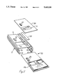
FIGS. 5 and 6 are exploded views showing assembly of a meter; and
FIGS. 7 and 8 are cross-sectional views in the direction of the arrows VII--VII of FIG. 6.
DESCRIPTION OF THE PREFERRED EMBODIMENTS
Referring to FIGS. 1 and 2, there is illustrated a hand-held instrument, in this case a moisture meter 1. The meter 1 comprises a housing blank 2 of channel-shaped construction. The housing blank has a base which forms a front wall 3 to which a label 4 is adhered. End caps 5 are secured to each end of the blank 2 by self-tapping screws 5(a) and 5(b). The back of the meter 1 comprises a backing plate 7 to which are secured a pair of electrode pads 8 for capacitive moisture detection. The label 4 which is adhered to the front wall 3 is of flexible plastics material and includes a transparent portion 9 which is aligned with an aperture, not shown in FIGS. 1 and 2, having a similar shape in the front wall 3 to form a window for the instrument. The label 4 has a cut-out aperture 10 to allow access to switches 11 connected to a circuit within the meter 1. Apertures 12 in the front wall 3 are shown by interrupted lines and these are covered by the label 4. Switches within the meter 1 may be operated using the label 4 because of its flexibility.
Referring to FIG. 3, there is shown an alternative construction of moisture meter indicated by the reference numeral 13 in which parts similar to those described with reference to FIGS. 1 and 2 are identified by the same reference numerals. In this embodiment, there is an end cap 14 which carries sensor pins 15 and a strap 16 for the meter. The strap 16 passes through holes in a cover 17 for the pins 15 so that it may be slid on and off the pins 15, when desired, without falling from the meter 13. In this embodiment, the meter does not have electrode pads 8, however, it is possible that the backing plate 7 would have electrode pads 8 to improve versatility of use of the instrument.
Referring now to FIGS. 4 to 8 inclusive, instruments of the invention are shown in more detail and their production methods are also shown. Again, parts similar to those described with reference to the previous drawings are identified by the same reference numerals. The front wall 3 has a shallow longitudinal channel 18 for reception of the sliding switches 11. A display aperture 19 for alignment with the window 9 in the label 4 is shown, as are the apertures 12. The side walls 6 have inwardly-directed longitudinal strengthening ribs 20 which form a pair of opposed inner grooves. The ribs 20 have curved inner surfaces to form a bearing surface for reception of the self-tapping screws 5(a) and 5(b).
The side walls 6 also include longitudinal strengthening ribs 21 which form a pair of opposed outer grooves.
Production of the moisture meters involves initially extruding aluminium lengths having the cross-section shown in FIG. 4. A length is then cut to individual blanks which are of the correct size for production of a particular moisture meter. In this embodiment all moisture meters within a range of different meters have the same length.
Subsequently, the apertures 10, 12 and 19 are stamped in the front wall 3. It has been found that because the housing blank 2 is of channel-shaped construction, tooling for stamping of the front wall 3 is relatively simple as it may easily access the rear of the front wall 3 for support during the stamping operation. Thus, stamping is considerably less expensive than would be the case, for example, if the housing blank were of tubular cross-section. For each of the different types of meters the same stamping tool is used because redundant apertures are simply covered over by the label.
Referring now to FIG. 5, a moisture meter circuit 22 is inserted into the housing blank 2 by sliding it into the pair of opposed inner grooves 20 until it is in correct alignment with the apertures in the front wall 3. In more detail, there are tactile switches 23 and a pointer and scale indictor 24. The switches 23 are aligned with the apertures 12 and the indicator 24 is aligned with the aperture 19. The moisture meter which is being produced in this embodiment is not exactly similar to that shown in FIG. 1. In this embodiment, there are no switches 11 on the circuit 22 and thus, the channel 18 in the housing blank 2 is filled in using a plastics strip 25. As shown in FIG. 6, the backing plate 7 is then inserted by simply sliding it in the grooves 21. At this stage, both the circuit 22 and the backing plate 7 are held in position and are flush with the ends of the housing blank 2. The end cap 14 is then placed in position at the top end of the housing blank and is secured in position using the self-tapping screws 5(a) and 5(b) which engage the grooves 20. At the bottom of the housing blank 2, the end cap 5 is secured in position in a similar manner.
Finally, a polyester adhesive label 26 (which is different from the label 4) is adhered to the front wall 3 so that the window 9 is in alignment with the aperture 19. The label 26 has indicia 27 which are aligned with the apertures 12 so that the rear of the label 26 adheres to the tactile switches 23 so that they may be operated through the apertures 12 in use. This is shown clearly in FIGS. 7 and 8. It will be noted from these drawings that the circuit 22 may not be removed by removal of an end cap 5 or 14 and sliding out in the inner grooves 20, because the switches 23 would abut against the side of the apertures 12. This helps to improve the tamper-proof nature of the instrument.
It will be appreciated that the production method of the invention is extremely simple as it involves relatively few parts. Further, individual production operations are very simple, for example, the circuit and the backing plate are simply slid into position and the end cap may be easily secured in position also. The production method is also versatile because the same housing blanks may be used for different circuits, sensors being used by simple selection of an end cap or backing plate and different user interfaces being created by simple selection of a front label which corresponds to the circuit being used. In fact it has been found that production costs of the method of the invention, in comparison with the traditional method of using moulded plastic halves as the instrument casing have almost halved.
It will also be appreciated that the hand-held instrument of the invention has considerable strength because of the ribs 20 and 21 in the side walls 6. Even if the housing blanks were not of metal construction (plastics, for example) there would still be considerable resistance to distortion because of these features.
Not only is the production method of the invention simple and thus inexpensive, but the parts used are also inexpensive. For example, the housing blank which is produced by aluminium extrusion may be produced considerably less expensively than a moulded plastics housing, which would require expensive moulds.
The invention is not limited to the embodiments hereinbefore described, but may be varied in construction and detail.

Claims (8)

We claim:
1. A hand-held sensing instrument comprising:
a) a housing blank which is channel-shaped in cross-section and which includes:
(i) a base having apertures and which forms an instrument front wall, and
(ii) a pair of side walls;
b) an instrument circuit mounted behind the instrument front wall;
c) user interface devices being mounted on the instrument circuit, said devices being in registry with the apertures in the base forming the front wall;
d) a backing plate mounted behind the instrument circuit;
e) end caps secured to opposite ends of the housing blank; and
f) a sensor device.
2. A hand-held sensing instrument as claimed in claim 1, wherein a flexible label is adhered to the instrument front wall, the flexibility of the label facilitating user operation of the interface devices in registry with the apertures.
3. A hand-held sensing instrument as claimed in claim 1, wherein the end caps are held in position by removable thread cutting screws directly engaging grooves in the housing blank side walls.
4. A hand-held sensing instrument as claimed in claim 1, wherein the backing plate supports the sensor device for the instrument.
5. A hand-held sensing instrument as claimed in claim 4, wherein the backing plate is removably supported in opposed grooves formed by the housing blank side walls.
6. A hand-held sensing instrument as claimed in claim 1, wherein an end cap supports the sensor device for the instrument.
7. A hand-held sensing instrument as claimed in claim 6, wherein the sensor device is a pin, and the end cap further supports a strap for the instrument, the strap retaining a removable cover for the pin.
8. A hand-held instrument as claimed in claim 1, wherein the housing blank consists of extruded aluminum.
US07/923,376 1991-08-01 1992-07-31 Hand-held sensing instrument Expired - Lifetime US5415038A (en)

Applications Claiming Priority (2)

Application Number Priority Date Filing Date Title
IE2657/91 1991-08-01
IE265791 1991-08-01

Publications (1)

Publication Number Publication Date
US5415038A true US5415038A (en) 1995-05-16

Family

ID=11035902

Family Applications (1)

Application Number Title Priority Date Filing Date
US07/923,376 Expired - Lifetime US5415038A (en) 1991-08-01 1992-07-31 Hand-held sensing instrument

Country Status (4)

Country Link
US (1) US5415038A (en)
AU (1) AU2421292A (en)
WO (1) WO1993003330A1 (en)
ZA (1) ZA925517B (en)

Cited By (7)

* Cited by examiner, † Cited by third party
Publication number Priority date Publication date Assignee Title
US5821405A (en) * 1996-02-29 1998-10-13 Hydrolab Corporation Modular water quality apparatus and method
WO1999065547A1 (en) * 1998-06-19 1999-12-23 Abbott Laboratories Extruded metal housing with elastomeric ends for an infusion pump
EP0980201A1 (en) * 1998-08-12 2000-02-16 Ritto - Werk Loh GmbH & Co. KG Intercom apparatus
US6588931B2 (en) * 2000-12-07 2003-07-08 Delphi Technologies, Inc. Temperature sensor with flexible circuit substrate
US20090247242A1 (en) * 2008-03-25 2009-10-01 Motorola Inc Integral housing and user interface
US20130329345A1 (en) * 2012-06-11 2013-12-12 Hon Hai Precision Industry Co., Ltd. Housing structure and electronic device using the same
CN109238331A (en) * 2018-10-16 2019-01-18 安徽星鹏林业调查规划设计有限公司 A kind of exploration instrument for forest reserves protection

Families Citing this family (2)

* Cited by examiner, † Cited by third party
Publication number Priority date Publication date Assignee Title
US20100056231A1 (en) * 2008-08-30 2010-03-04 Motorola Inc Housing for Hand-Held Device with Extruded Element having Area of Bulk Material and Corresponding Method
US8430256B2 (en) 2008-09-03 2013-04-30 Motorola Mobility Llc Extruded housing for hand-held device with a cap for covering two or more adjacent sides

Citations (13)

* Cited by examiner, † Cited by third party
Publication number Priority date Publication date Assignee Title
DE359161C (en) * 1920-07-28 1922-09-21 Olof Frankman Device for the temporary emptying of the collecting container on harvesting machines
GB1183647A (en) * 1967-12-05 1970-03-11 Record Electrical Co Ltd Improvements in or relating to Instrument Cases.
US4209723A (en) * 1977-09-26 1980-06-24 Eaton Stamping Company Electric motor apparatus
US4287764A (en) * 1979-03-02 1981-09-08 Hartmann & Braun Aktiengesellschaft Fluid analyzer construction and housing
US4370613A (en) * 1979-10-02 1983-01-25 General Scanning, Inc. Galvanometer with molded outer layer under hoop stress
US4493987A (en) * 1983-01-31 1985-01-15 K-Line Industries, Inc. Counter
US4597291A (en) * 1983-09-23 1986-07-01 Ohkura Electric Co., Ltd. Connectible instrument casing
US4696189A (en) * 1985-04-13 1987-09-29 Brown, Boveri & Cie Ag Housing for a measuring device
US4718279A (en) * 1986-12-01 1988-01-12 Dwyer Instruments, Inc. Dual bourdon tube type sensing pressure transducer
US4791531A (en) * 1987-03-09 1988-12-13 Tech-S, Inc. Extruded enclosure for electrical apparatus
US4860901A (en) * 1986-04-03 1989-08-29 Brown, Boveri & Cie Ag Housing with a flexible shock protector for a portable measuring instrument
US4992635A (en) * 1989-07-31 1991-02-12 Marilyn L. Keegan Self locating push-button switch box
US5008775A (en) * 1988-09-13 1991-04-16 Honeywell Regelsysteme Gmbh Sensor and control module with improved sensor isolation

Patent Citations (13)

* Cited by examiner, † Cited by third party
Publication number Priority date Publication date Assignee Title
DE359161C (en) * 1920-07-28 1922-09-21 Olof Frankman Device for the temporary emptying of the collecting container on harvesting machines
GB1183647A (en) * 1967-12-05 1970-03-11 Record Electrical Co Ltd Improvements in or relating to Instrument Cases.
US4209723A (en) * 1977-09-26 1980-06-24 Eaton Stamping Company Electric motor apparatus
US4287764A (en) * 1979-03-02 1981-09-08 Hartmann & Braun Aktiengesellschaft Fluid analyzer construction and housing
US4370613A (en) * 1979-10-02 1983-01-25 General Scanning, Inc. Galvanometer with molded outer layer under hoop stress
US4493987A (en) * 1983-01-31 1985-01-15 K-Line Industries, Inc. Counter
US4597291A (en) * 1983-09-23 1986-07-01 Ohkura Electric Co., Ltd. Connectible instrument casing
US4696189A (en) * 1985-04-13 1987-09-29 Brown, Boveri & Cie Ag Housing for a measuring device
US4860901A (en) * 1986-04-03 1989-08-29 Brown, Boveri & Cie Ag Housing with a flexible shock protector for a portable measuring instrument
US4718279A (en) * 1986-12-01 1988-01-12 Dwyer Instruments, Inc. Dual bourdon tube type sensing pressure transducer
US4791531A (en) * 1987-03-09 1988-12-13 Tech-S, Inc. Extruded enclosure for electrical apparatus
US5008775A (en) * 1988-09-13 1991-04-16 Honeywell Regelsysteme Gmbh Sensor and control module with improved sensor isolation
US4992635A (en) * 1989-07-31 1991-02-12 Marilyn L. Keegan Self locating push-button switch box

Cited By (10)

* Cited by examiner, † Cited by third party
Publication number Priority date Publication date Assignee Title
US5821405A (en) * 1996-02-29 1998-10-13 Hydrolab Corporation Modular water quality apparatus and method
WO1999065547A1 (en) * 1998-06-19 1999-12-23 Abbott Laboratories Extruded metal housing with elastomeric ends for an infusion pump
US6305908B1 (en) 1998-06-19 2001-10-23 Abbott Laboratories Infusion pump extruded metal housing with elastomeric end caps
EP0980201A1 (en) * 1998-08-12 2000-02-16 Ritto - Werk Loh GmbH & Co. KG Intercom apparatus
US6588931B2 (en) * 2000-12-07 2003-07-08 Delphi Technologies, Inc. Temperature sensor with flexible circuit substrate
US20090247242A1 (en) * 2008-03-25 2009-10-01 Motorola Inc Integral housing and user interface
US8280459B2 (en) * 2008-03-25 2012-10-02 Motorola Mobility, Inc. Integral housing and user interface
US20130329345A1 (en) * 2012-06-11 2013-12-12 Hon Hai Precision Industry Co., Ltd. Housing structure and electronic device using the same
US9144165B2 (en) * 2012-06-11 2015-09-22 Hong Fu Jin Precision Industry (Shenzhen) Co., Ltd. Housing structure and electronic device using the same
CN109238331A (en) * 2018-10-16 2019-01-18 安徽星鹏林业调查规划设计有限公司 A kind of exploration instrument for forest reserves protection

Also Published As

Publication number Publication date
WO1993003330A1 (en) 1993-02-18
AU2421292A (en) 1993-03-02
ZA925517B (en) 1993-04-28

Similar Documents

Publication Publication Date Title
US5415038A (en) Hand-held sensing instrument
US5048118A (en) Combination dual loop antenna and bezel with detachable lens cap
CA2218985A1 (en) Electronic license plate architecture
DE69005774D1 (en) Multipurpose display module system for an electronic instrument.
DE69433173D1 (en) Device that affects an input signal
CA2124116A1 (en) Label generation apparatus
DE69430681T2 (en) Punch for an imaging device
ITTO940032A0 (en) TEST MODULES WITH EXPANDABLE DIAPHRAGM AND CONNECTORS.
US5315775A (en) Digital sign
DE69504014D1 (en) Anti-theft device for attaching an anti-theft label
IE70305B1 (en) A hand-held sensing instrument
US6094983A (en) Gauge having an indicia-bearing insert
US3948209A (en) Indicator apparatus
DE69203696D1 (en) Device for attaching a glass to a vibrating support element, in particular on the screen of a dashboard.
DE69024125D1 (en) Data processing arrangement with a display area for word processing
US5031870A (en) Display card mounting device
US4149333A (en) Assemblable display device for mailboxes and the like
DE102008013036B4 (en) display device
US4186386A (en) Instrument housing
JP2949173B1 (en) Sample display equipment for vending machines
JPH0438544Y2 (en)
JPH0452909Y2 (en)
JPH08264964A (en) Housing case of electric equipment
GB9008059D0 (en) An illuminable sign
JPH0142127Y2 (en)

Legal Events

Date Code Title Description
AS Assignment

Owner name: RYNHART RESEARCH LIMITED, IRELAND

Free format text: ASSIGNMENT OF ASSIGNORS INTEREST.;ASSIGNORS:RYNHART, ALAN;FARRELL, BRENDAN;FALLON, SEAN;REEL/FRAME:006233/0482

Effective date: 19920723

STCF Information on status: patent grant

Free format text: PATENTED CASE

FPAY Fee payment

Year of fee payment: 4

REMI Maintenance fee reminder mailed
FEPP Fee payment procedure

Free format text: PAYOR NUMBER ASSIGNED (ORIGINAL EVENT CODE: ASPN); ENTITY STATUS OF PATENT OWNER: SMALL ENTITY

FPAY Fee payment

Year of fee payment: 8

SULP Surcharge for late payment

Year of fee payment: 7

FPAY Fee payment

Year of fee payment: 12