US5417536A - Lift truck weighing apparatus - Google Patents

Lift truck weighing apparatus Download PDF

Info

Publication number
US5417536A
US5417536A US08/159,668 US15966893A US5417536A US 5417536 A US5417536 A US 5417536A US 15966893 A US15966893 A US 15966893A US 5417536 A US5417536 A US 5417536A
Authority
US
United States
Prior art keywords
load
platform
weight
ball
load sensors
Prior art date
Legal status (The legal status is an assumption and is not a legal conclusion. Google has not performed a legal analysis and makes no representation as to the accuracy of the status listed.)
Expired - Fee Related
Application number
US08/159,668
Inventor
Werner J. Cech
Current Assignee (The listed assignees may be inaccurate. Google has not performed a legal analysis and makes no representation or warranty as to the accuracy of the list.)
GMP Surgical Solutions Inc
Cech Corp
Original Assignee
Cech Corp
Priority date (The priority date is an assumption and is not a legal conclusion. Google has not performed a legal analysis and makes no representation as to the accuracy of the date listed.)
Filing date
Publication date
Application filed by Cech Corp filed Critical Cech Corp
Priority to US08/159,668 priority Critical patent/US5417536A/en
Assigned to CECH CORPORATION reassignment CECH CORPORATION ASSIGNMENT OF ASSIGNORS INTEREST (SEE DOCUMENT FOR DETAILS). Assignors: CECH, WERNER J.
Priority to GB9423470A priority patent/GB2284270B/en
Priority to CA002136488A priority patent/CA2136488A1/en
Priority to EP94118423A priority patent/EP0655612B1/en
Priority to DE69409069T priority patent/DE69409069D1/en
Application granted granted Critical
Publication of US5417536A publication Critical patent/US5417536A/en
Assigned to GMP SURGICAL SOLUTIONS, INC. reassignment GMP SURGICAL SOLUTIONS, INC. ASSIGNMENT OF ASSIGNORS INTEREST (SEE DOCUMENT FOR DETAILS). Assignors: WINER, DONALD B.
Anticipated expiration legal-status Critical
Expired - Fee Related legal-status Critical Current

Links

Images

Classifications

    • GPHYSICS
    • G01MEASURING; TESTING
    • G01GWEIGHING
    • G01G19/00Weighing apparatus or methods adapted for special purposes not provided for in the preceding groups
    • G01G19/08Weighing apparatus or methods adapted for special purposes not provided for in the preceding groups for incorporation in vehicles
    • G01G19/083Weighing apparatus or methods adapted for special purposes not provided for in the preceding groups for incorporation in vehicles lift truck scale
    • BPERFORMING OPERATIONS; TRANSPORTING
    • B62LAND VEHICLES FOR TRAVELLING OTHERWISE THAN ON RAILS
    • B62BHAND-PROPELLED VEHICLES, e.g. HAND CARTS OR PERAMBULATORS; SLEDGES
    • B62B2203/00Grasping, holding, supporting the objects
    • B62B2203/50Grasping, holding, supporting the objects comprising weighing means

Abstract

A pallet truck has a rigid frame mounting a plurality of load cells. Ball and socket coupling devices are connected to the load cells and support a platform assembly. The frame and platform assembly are able to be elevated to lift and support an object to be weighed on the platform assembly. The ball and socket coupling devices enable the platform assembly to shift laterally to dissipate lateral forces and then restore the platform assembly to a position wherein the weight of the object is transmitted along associated load axes of the load cells for accurately measuring the weight of the object.

Description

This invention relates generally to a material lifting and handling truck and more particularly to such truck equipped with apparatus for weighing an object lifted by the truck.
BACKGROUND OF THE INVENTION
Devices suitable for weighing large, heavy objects, such as tote containers of the type used for the storage and handling of liquid chemicals in bulk, have been, for the most part, limited to stationary floor scales of 5,000 pounds or more weighing capacity. Not all facilities that utilize tote containers are equipped with such floor scales and for those that are it is not always convenient or practical to transport the containers to and from the floor scales for weighing.
Some of the prior lift trucks include weighing devices wherein objects, such as tote containers, can be lifted by the trucks and weighed. The accuracy of the weighing apparatus of such lifting trucks is, at best, about 98%. The contents of a typical container weigh about 5,000 pounds, equating to a weighing error of known apparatus of plus or minus 100 pounds. One reason for the relatively high error of prior art apparatus is believed to be lateral loading of the load sensors caused by shifting of the container's contents, uneven flooring, and the like which produces a false reading of the weight of the container and its contents.
An object of this invention is to improve the accuracy of such lift truck weighing apparatus.
SUMMARY OF THE INVENTION AND ADVANTAGES
Lift truck apparatus for lifting and weighing large heavy objects includes a wheeled frame supporting load sensing means having a loading axis along which the weight of an object is to be applied for accurately measuring its weight. A weighing platform is provided and selectively elevated along with the frame by lifting means for lifting and supporting the object on the weighing platform. Load alignment means are coupled to the load sensing means for normally supporting the platform in an aligned position with respect to the loading axis wherein the weight of the object is transmitted to the load sensing means along the loading axis. The load alignment means, however, enables the platform to oscillate laterally of the loading axis to dissipate any lateral forces acting on the object and thereafter self-restore the platform to the aligned position for more accurate measurement of the weight of the object, as compared to known prior lift and weigh devices.
BRIEF DESCRIPTION OF THE DRAWINGS
A presently preferred embodiment of the invention is illustrated in the accompanying drawings, wherein:
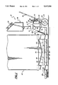
FIG. 1 is a fragmentary side elevational view of the lift truck apparatus illustrating the lifting apparatus in its lowered position;
FIG. 2 is a view like FIG. 1 but with the lifting apparatus shown in an elevated position;
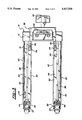
FIG. 3 is a top view of the apparatus shown with the weigh deck and fork covers removed;
FIG. 4 is a view like FIG. 3 but with the fork covers and weigh deck installed;
FIG. 5 is an enlarged, sectional view taken along the line 5--5 of FIG. 4; and
FIG. 6 is an enlarged sectional view of the ball and socket coupling device taken along the line 6--6 of FIG. 5.
DETAILED DESCRIPTION
Lift truck weighing apparatus constructed according to a presently preferred embodiment of the invention is indicated generally by the reference numeral 10 and comprises a pallet lifting truck of conventional construction including a rigid frame 12 having a base 14 mounting a pair of steerable rear wheels 16 and a pair of laterally spaced forks 18, 20 each of which project forwardly of the base portion 14 and mounts a set of front wheels 22.
The base portion 14 includes a wheel support block 24 journaling a vertical steering shaft 26 coupled at its lower end to the axle of the rear wheels 16 and fixed at its upper end to the cylinder 28 of a hydraulic jack 30. A piston 32 projects out of the cylinder 28 and is secured at its upper free end to a rigid lifting arm 34 of the base portion 14. A control handle 36 is coupled to the cylinder 28 enabling the operator to steer the rear wheels 16 by moving the handle 36 to the left or right in a conventional manner. The handle 36 may also be rocked up and down to actuate the jack 30 and extend the piston 32 thereby elevating the lifting arm 34 from the lowered position shown in FIG. 1 to the raised position shown in FIG. 2. A conventional linkage mechanism 38 interconnects the wheel support block 24, the base portion 14, and the front wheels 22 and is operable to extend the front wheels 22 below the forks 18, 20 for elevating the forks 18, 20 together with the base portion 14 as shown in FIGS. 1 and 2.
A pair of rigid channel members 40, 42 are provided beneath the forks 18, 20, respectively, and are welded or otherwise fixed at their rearward ends to the base 14 and secured at their forward ends to fulcrum axles 44, 46 of the linkage mechanism 38 for lifting movement with the remaining portions of the frame 12. The channels 40, 42 are constructed of steel plate material each having a flat base 40 supported horizontally beneath the forks 18, 20 and a pair of upstanding sidewalls 50, 52 arranged on opposite lateral sides of each fork 18, 20 in spaced relation thereto.
Load sensing means comprising four known load sensors or cells 54 are mounted by suitable fasteners 55 to the bases 48 of the channels 40, 42 in the front and back paired arrangement illustrated in FIG. 3 and are electronically coupled by lines 56 to a battery powered known programmable process controller 58 supported by the base 14. A control panel 59 is supported by the base within the view and reach of the operator.
The load cells 54 mount a weighing platform assembly 60 via ball and socket load-aligning coupling devices 62 for supporting the weight of an object such as a tote container 63. As shown best in FIG. 5 and 6, each of the load cells 54 has a vertical loading axis A along which the weight of an object may be transmitted to enable the load cells 54 to determine the weight of the object. Each of the load cells 54 is provided with a threaded aperture 64 extending coaxially of the loading axis A and accommodating the threaded shank 66 of a lower socket member 68 of the coupling device 62. The upper end of the aperture 64 is countersunk to form a recess 70 for the accommodation of an enlarged head or receiver cup 72 of the lower socket member 68. The receiver cup 72 is provided with an upwardly concave recess or indentation 74 whose lowest point or peak 76 lies along the loading axis A of the load cell 54. Access ports 77 are provided in the bases 40 of channel members 40, 42 for accessing the shanks 66 of the socket members 68 for threading the socket members 68 into engagement with their associated load cells 54.
A corresponding plurality of upper socket members 78 are secured to the platform assembly 60 in the identical spaced arrangement as that of the lower socket members 68. The upper socket members 78 are of substantially identical configuration to those of the lower socket members 68 and as such include threaded shank portions 80 and an enlarged head or receiver cup 82 provided with a concave recess or indentation 84 of the same radial curvature as the recess 74 and radii of cups 72, 82, whose peak 86 lies along a load transmitting axis B of the platform assembly 60 associated with each load cell 54.
As illustrated in FIGS. 4-6, the platform assembly 60 includes a pair of inverted U-shaped fork covers 88 each of which has a horizontal top wall 92 overlying the associated fork and a pair of laterally spaced sidewalls 94 overlying the sidewalls 50, 52 of the associated channel members 40, 42. The threaded shanks 80 of the upper socket members 78 are received in threaded apertures 96 of the top wall 92 thereby securing the upper socket members 78 to the fork covers 88, 90. The receiver cups 82 project below the underside of the top wall 92 and the threaded shanks 80 project above the upper surface of the top wall 92.
The platform assembly 60 also includes a rigid weigh deck 98 that may be of open frame construction supported on the fork covers 88, 90, as illustrated in FIG. 4. The weigh deck 98 includes a pair of laterally spaced, longitudinal sections 100, 102 overlying the fork covers 88, 90, respectively, a pair of transverse end sections 104, 106 extending between and interconnecting the longitudinal sections 100, 102 at front and back ends thereof, and an intermediate cross section 108 interconnecting the longitudinal sections 100, 102 midway between the end sections 104, 106. The weigh deck 98 has a plurality of load transferring support legs or sleeves 110 engaging the top of the fork covers 88, 90 to space the weigh deck 98 above the fork covers 88, 90. The sleeves 110 form cavities for reception of the projecting shanks 80 of the upper socket members 78, as illustrated in FIGS. 5 and 6. The weigh deck 98 is separable from the fork covers 88, 90 by lifting the deck 98 off the covers 88, 90. The cavity formed by the inner wall of each support sleeve 110 is relatively larger in diameter than that of the shank 80 to enable the weigh deck 98 to shift laterally on the fork covers 88, 90 by a small amount when a lateral force is applied to the deck 98.
A ball 112 is accommodated within the opposing recesses 74, 84 of each upper and lower socket pair. The ball 112 reacts with point contact between the concave walls of the recesses to transmit the weight of the object from the platform assembly 60 to the load cells 54. The radius of the ball 112 is less than the radius of curvature of each of the recesses 74, 84. The weight of the platform assembly acting on the ball and socket coupling devices 62 urges the socket members 68, 70 and ball 112 of each device to seek the center of curvature of each of the recesses 74, 84 so that the load transmitting axis B of the platform assembly are aligned with the loading axis A of the respective load cells 54, as illustrated in FIGS. 5 and 6. The ball and recess connection, however, enables the fork covers 88, 90 and weigh deck 98 to oscillate laterally of the loading axis when a lateral force acts on the container 63. The self-restoring force of the ball and recess connections dissipates such lateral force and restores the platform assembly 60 to the aligned position.
THE OPERATION
FIG. 1 shows a tote container 63 that is to be lifted and transported, and simultaneously weighed by the apparatus 10. When filled, it is common for the bottom wall 116 of the container 63 to bulge or belly downwardly, as shown exaggerated in FIG. 1, under the weight of the contents. To lift and weigh such a container, the forks and weigh deck are maneuvered beneath the container 63 with the intermediate cross portion 108 located under the belly 116. The weigh deck 98 and fork covers 88, 90 are provided with upwardly and rearwardly projecting dashboard portions 118, 120, respectively, overlying the base 14 of the frame 12 to ensure that the container 63 is supported only on the platform assembly 60 and not directly by the frame 12. The hydraulic jack 30 is actuated to elevate the frame 12 and platform assembly 60 to the position shown in FIG. 2 for lifting and supporting the entire weight of the container 63 on the weigh deck 98. As shown in FIG. 2, the intermediate cross portion 108 engages and lifts the belly 116 so that the container 63 is supported evenly on the weigh deck 98.
The weight of the container 63 is transmitted via the support sleeves 110 through the fork covers 88, 90 to the upper socket members 78 and then to the lower members 68 through the balls 112. The downward axial loading force of the platform assembly 60 and container 63 urges the platform assembly 60 toward the aligned position. If, however, there are lateral forces acting on the container 63 the weigh deck 98 is able to shift laterally a small amount on the fork covers 88, 90 and the ball and socket coupling devices 62 further enable the platform assembly 60 to oscillate laterally relative to the loading axis A. The axial restoring force dissipates such lateral forces bringing the platform assembly 60 back into the aligned position so that the entire weight of the container 63 is transmitted to the load cells 54 along the loading axes A for accurate measurement of the weight of the object.
The load cells 54 generate cumulative weight signal information processed by the controller 58 for calculating the weight of the container 63 and/or its contents. The measured weight may be displayed at the control panel 59 or electronically recorded. The apparatus has been shown to be accurate to within 0.1% to 0.2% for loads of up to about 5,000 pounds.
The apparatus 10 also has utility at time of filling the container in that the operator can lift the container prior to filling and either observe the accumulating weight of the material introduced into the container as measured by the apparatus or else electronically couple the apparatus to an automated valve for filling the container with a precise amount of material based on program information provided to the controller 58.

Claims (16)

I claim:
1. Lift truck apparatus for lifting and weighing an object, said apparatus comprising:
a wheeled frame having a plurality of laterally spaced forks;
a rigid weighing platform;
lift means for elevating said frame and said platform to lift and support an object on said platform;
a plurality of load sensors supported by said forks at spaced apart locations each having a loading axis along which the weight of an object is to be applied for accurately measuring its weight; and
a plurality of load-aligning coupling devices corresponding in number and spacing to said load sensors each coupled to an adjacent one of said load sensors for normally supporting said platform in an aligned position with respect to said loading axis wherein the weight of the object is transmitted to said load sensors along said loading axis, while enabling said platform to oscillate laterally in a plurality of directions relative to said loading axis to dissipate lateral forces acting on the object and self-restore said platform to said aligned position for measuring the weight of the object, said platform extending laterally between said forks for transferring loads applied to the platform between said spaced forks axially to said load sensors via said coupling devices.
2. The apparatus of claim 1 wherein each of said load sensors comprises a plurality of load cells.
3. The apparatus of claim 2 wherein each of said load-aligning coupling devices comprises ball and socket coupling devices secured to said load cells and supporting said platform.
4. The apparatus of claim 3 wherein each of said ball and socket coupling devices comprises a lower socket member attached to an associated one of said load cells along said loading axis and an upper socket member secured to said platform, said socket members having opposing concave recesses, and a ball accommodated within each of said opposing recesses, said ball having a radius smaller than the radius of curvature of said recesses.
5. The apparatus of claim 4 wherein said platform includes a bottom portion mounting said upper socket members and a separate rigid weigh deck portion having a plurality of support legs engaging said weigh deck above said bottom portion.
6. The apparatus of claim 5 wherein said support legs have a sleeve construction providing a cavity within said support legs and said upper socket members including shank portions projecting above said bottom portion and received in said cavities of said support legs.
7. The apparatus of claim 6 wherein said support leg cavities are relatively larger in diameter than that of said shank portions enabling said weigh deck to shift laterally on said bottom portion.
8. The apparatus of claim 5 wherein said frame includes a base portion mounting a pair of forwardly projecting, laterally spaced forks and said bottom portion comprises a pair of laterally spaced fork covers overlying said forks, said weigh deck including a pair of laterally spaced longitudinal sections overlying said fork covers, a pair of transverse end sections extending transversely between and interconnecting said longitudinal sections, and an intermediate cross section spanning said longitudinal sections between said end sections.
9. The apparatus of claim 8 wherein said fork covers and said weigh deck include dashboard portions overlying said base portion of said frame to shield said base portion against direct supportive contact by the object when supported on said platform.
10. The apparatus of claim 2 wherein said frame includes a pair of laterally spaced channel members each mounting two of said load cells.
11. The apparatus of claim 10 wherein said platform includes a pair of laterally spaced fork covers overlying said channel members and a weigh deck supported on said fork covers.
12. The apparatus of claim 11 wherein said weigh deck is separable from said fork covers.
13. The apparatus of claim 2 wherein said load sensors include a process controller electronically coupled to each of said load cells for receiving cumulative input information from said load cells representative of the load applied to each load cell and processing said input information to calculate the weight of the object.
14. Lifting and weighing apparatus, comprising:
a rigid frame having a base portion mounting steerable rear wheels and a pair of laterally spaced forks secured at one end to said base portion and projecting forwardly therefrom to free ends mounting front wheels;
a pair of laterally spaced rigid channel members extending beneath said forks and fixed at one end to said base portion of said frame and supported at opposite ends by said front wheels;
a plurality of load sensors mounted on said channel members each of which has a vertical loading axis along which the weight of an object is to be transmitted for accurately measuring the weight of the object;
a platform assembly including a pair of laterally spaced fork covers overlying said forks, and a rigid weigh deck having an open frame construction including a pair of laterally spaced longitudinal sections overlying said fork covers, a pair of transverse end sections extending between and interconnecting said longitudinal sections, and an intermediate cross section bridging said longitudinal sections between said end sections, said weigh deck including a plurality of sleeve-like support legs corresponding in number and arrangement to said load sensor axes engaging said fork covers and supporting the remainder of said weigh deck spaced above said fork covers;
ball and socket coupling devices interconnecting said platform assembly and said load sensors, each of said coupling devices including a lower socket member secured to an associated one of said load sensors and an adjacent upper socket member secured to an associated one of said fork covers, said upper socket members having shank portions projecting above said fork covers and received in said support legs of said weigh deck, said socket members having opposing arcuately concave recesses supporting a ball therebetween, the peak of said lower socket recess lying along said loading axis of the associated load sensor and the peak of the upper socket recess lying along an associated load transmitting axis of said platform assembly, said ball having a radius smaller than that of the curvature of each of said recesses causing said ball to self-align said load transmitting axes of said platform assembly with the associated loading axes of said load sensor; and
lifting means for selectively elevating said frame and said platform assembly to lift and support the weight of the object on said platform assembly thereby transmitting the weight of the object to said load sensors via said ball and socket coupling devices, the configuration of the ball and socket connections enabling said platform assembly to oscillate in all directions laterally of said loading axis to dissipate any lateral forces acting on the object and thereafter restore said platform assembly to the self-aligned position wherein all of the weight of the object is transmitted to the load sensors along the loading axis.
15. Lift truck apparatus for lifting and weighing an object, said apparatus comprising:
a wheeled frame;
a weighing platform;
lift means for elevating said frame and said platform to lift and support an object on said platform;
a plurality of load sensors mounted on said frame at spaced apart locations each having a loading axis along which the weight of an object is to be applied for accurately measuring its weight; and
a plurality of load-aligning coupling devices corresponding in number and spacing to said load sensors each coupled to an adjacent one of said load sensors for normally supporting said platform in an aligned position with respect to said loading axis wherein the weight of the object is transmitted to said load sensors along said loading axis, while enabling said platform to oscillate laterally in a plurality of directions relative to said loading axis to dissipate lateral forces acting on the object and self-restore said platform to said aligned position for measuring the weight of the object, said platform having a plurality of load transfer legs corresponding in number to said load sensors and in corresponding overlying spaced relation to said coupling devices for transmitting the load on said platform to said coupling devices through said legs.
16. Lifting and weighing apparatus, comprising:
a rigid frame having a base portion mounting steerable rear wheels and a plurality of laterally spaced forks secured at one end to said base portion and projecting forwardly therefrom to free ends mounting front wheels;
a plurality of load sensors carried by said forks each having a vertical loading axis along which the weight of an object is to be transmitted for accurately measuring the weight of the object;
a platform assembly including a corresponding plurality of laterally spaced fork covers overlying said forks, and a separate rigid weigh deck overlying and spanning said fork covers, said weigh deck including a plurality of support legs corresponding in number and arrangement to said load sensor axes engaging said fork covers and supporting the remainder of said weigh deck at a level spaced above said fork covers;
ball and socket coupling devices interconnecting said platform assembly and said load sensors, each of said coupling devices including a lower socket member secured to an associated one of said load sensors and an adjacent upper socket member secured to an associated one of said fork covers, said socket members having opposing arcuately concave recesses supporting a ball therebetween, the peak of said lower socket recess lying along said loading axis of the associated load sensor and the peak of the upper socket recess lying along an associated load transmitting axis of said platform assembly, said ball having a radius smaller than that of the curvature of each of said recesses causing said ball to self-align said load transmitting axes of said platform assembly with the associated loading axes of said load sensor; and
lifting means for selectively elevating said platform assembly to lift and support the weight of the object on said platform assembly thereby transmitting the weight of the object to said load sensors via said ball and socket coupling devices, the configuration of the ball and socket connections enabling said platform assembly to oscillate in a plurality of directions laterally of said loading axis to dissipate any lateral forces acting on the object and thereafter restore said platform assembly to the self-aligned position wherein all of the weight of the object is transmitted to the load sensors along the loading axis.
US08/159,668 1993-11-30 1993-11-30 Lift truck weighing apparatus Expired - Fee Related US5417536A (en)

Priority Applications (5)

Application Number Priority Date Filing Date Title
US08/159,668 US5417536A (en) 1993-11-30 1993-11-30 Lift truck weighing apparatus
GB9423470A GB2284270B (en) 1993-11-30 1994-11-21 Lift truck weighing apparatus
CA002136488A CA2136488A1 (en) 1993-11-30 1994-11-23 Lift truck weighing apparatus
EP94118423A EP0655612B1 (en) 1993-11-30 1994-11-23 Fork lift truck with weigh deck
DE69409069T DE69409069D1 (en) 1993-11-30 1994-11-23 Forklift with pad

Applications Claiming Priority (1)

Application Number Priority Date Filing Date Title
US08/159,668 US5417536A (en) 1993-11-30 1993-11-30 Lift truck weighing apparatus

Publications (1)

Publication Number Publication Date
US5417536A true US5417536A (en) 1995-05-23

Family

ID=22573482

Family Applications (1)

Application Number Title Priority Date Filing Date
US08/159,668 Expired - Fee Related US5417536A (en) 1993-11-30 1993-11-30 Lift truck weighing apparatus

Country Status (5)

Country Link
US (1) US5417536A (en)
EP (1) EP0655612B1 (en)
CA (1) CA2136488A1 (en)
DE (1) DE69409069D1 (en)
GB (1) GB2284270B (en)

Cited By (30)

* Cited by examiner, † Cited by third party
Publication number Priority date Publication date Assignee Title
WO1996020391A1 (en) * 1994-12-27 1996-07-04 Friedman, Mark, M. Built-in weighing scale
US6124554A (en) * 1999-06-01 2000-09-26 Muckle; Thomas A. Portable pallet scale
US6222137B1 (en) 1998-08-04 2001-04-24 Wayac Inc. Dolly type drum scale
US6600111B2 (en) * 2001-07-13 2003-07-29 Gerald S. Simons Portable weigh scale system for use with vehicles having lift truck forks or the like
US20030234122A1 (en) * 2002-06-19 2003-12-25 Kroll William P. Fork tine scale technology
US6730861B1 (en) * 1999-11-04 2004-05-04 Weigh Point Incorporated Weigh sensed lift truck forks
US6764269B1 (en) 2003-02-04 2004-07-20 Anthony J. Cannata Frame apparatus mountable on a forklift
US20040140136A1 (en) * 2002-10-12 2004-07-22 Simons Gerald S. Hand truck weighing device and weighing method
US20040226755A1 (en) * 2003-05-13 2004-11-18 Pottebaum James R. Vehicle load weighing system and load cells for such systems
US20050023051A1 (en) * 2003-07-31 2005-02-03 Mark Toomey Tiller-steered industrial truck
US6855894B1 (en) * 1999-07-12 2005-02-15 Ravas Europe B.V. Mobile lifting device and weighing device therefor
US20050117434A1 (en) * 2003-12-01 2005-06-02 Seong-Hwi Song Semiconductor memory device
US7089803B1 (en) 2005-10-28 2006-08-15 Huber Engineered Woods Llc Panel performance testing system
US20060291986A1 (en) * 2005-06-28 2006-12-28 Vestil Manufacturing Corp. Storage device for use with a pallet jack
US20070041820A1 (en) * 2005-08-01 2007-02-22 Simons Gerald S Fork cover having weighing capability
US20080041638A1 (en) * 2005-08-01 2008-02-21 Simons Gerald S Low Profile Load Cell
US20080224433A1 (en) * 2007-03-12 2008-09-18 Mitchell Olin Setzer Portable apparatus for transporting items with a powered lifting feature
US20080236293A1 (en) * 2007-04-02 2008-10-02 Campagnolo S.R.L. Instrument-equipped bicycle component and detection unit for equipping such a component
US20080308359A1 (en) * 2007-06-15 2008-12-18 Waltz Lucas B Quick change load wheel assembly
US20100212972A1 (en) * 2007-07-25 2010-08-26 Mirraview Pty Ltd Vehicle for weighing an item
US20100320034A1 (en) * 2007-06-15 2010-12-23 Crown Equipment Corporation Outrigger assembly with quick change load wheel assembly
US20110073822A1 (en) * 2009-09-25 2011-03-31 Jiang Chen Hydraulic jack capable of displaying load and overload warning
US20110130865A1 (en) * 2007-03-12 2011-06-02 Setzer Sr Mitchell Olin Method of manually transporting items
US20140224588A1 (en) * 2011-07-06 2014-08-14 Ravas Europe B.V. Device, carrying body and lifting vehicle
US20150231583A1 (en) * 2014-02-20 2015-08-20 Stephen B. Maguire Liquid color cart and method for liquid color dispensing
WO2016186959A1 (en) * 2015-05-15 2016-11-24 Tms International Corporation Mobile pallet scale
US20190270468A1 (en) * 2016-11-14 2019-09-05 Ravas Europe B.V. Pallet truck
CN110877877A (en) * 2019-12-19 2020-03-13 昆山重拓机械有限公司 Electronic scale type hydraulic carrier
US11104558B2 (en) 2018-12-27 2021-08-31 Crown Equipment Corporation Load wheel assembly for preventing axial and rotational movement of an axle
US11413375B2 (en) 2014-03-21 2022-08-16 University of Pittsburgh—of the Commonwealth System of Higher Education Methods for preparation of a terminally sterilized hydrogel derived from extracellular matrix

Families Citing this family (8)

* Cited by examiner, † Cited by third party
Publication number Priority date Publication date Assignee Title
FR2865032B1 (en) * 2004-01-08 2006-09-29 Balea MOBILE WEIGHING BASE
BE1016392A3 (en) * 2004-12-23 2006-10-03 Vliet Ronny Van De Integrated support chassis weighing element.
GR1006315B (en) * 2005-10-19 2009-03-19 Παναγιωτης Φωτιαδης Electronic balance mounted on forklift trucks.
US7361852B2 (en) * 2006-07-07 2008-04-22 Mettler-Toledo Ag Weighing module
WO2008092253A1 (en) * 2007-01-30 2008-08-07 Simons Gerald S Weighing device
EP2028460A1 (en) * 2007-08-22 2009-02-25 Van de Vliet, Ronny weighing module
CN103613052B (en) * 2013-12-06 2016-03-30 无锡爱一力机械有限公司 A kind of weighting apparatus of transport trolley
AU2016325866A1 (en) * 2015-09-23 2018-04-12 Oliver Innovation Pty Ltd Load carrying apparatus

Citations (9)

* Cited by examiner, † Cited by third party
Publication number Priority date Publication date Assignee Title
US2358770A (en) * 1940-02-08 1944-09-19 Yale & Towne Mfg Co Load weighing lift truck
US3063576A (en) * 1960-07-11 1962-11-13 Chain Belt Co Weighing means for fork-lift trucks
DE1913527A1 (en) * 1968-04-17 1969-10-30 Voest Ag Vehicle for transporting and weighing metallurgical vessels
US4638876A (en) * 1984-10-05 1987-01-27 Franz Balduin Weighing apparatus
US4666004A (en) * 1986-05-01 1987-05-19 Pallet Truck Scale Corporation Pallet truck with weighing scale
US4899840A (en) * 1989-06-22 1990-02-13 Boubille Jacques C Apparatus for weighing a pallet with a load thereon for use with a vehicle having tines or the like
NL8901884A (en) * 1989-07-20 1991-02-18 Leendert Leyendekker Forklift truck with load measuring and recording system - uses pressure sensors mounted inside horizontal forks
WO1991008977A1 (en) * 1989-12-18 1991-06-27 Jensen Bjoern Holger A lifting device such as a lifting cart with means for measuring the weight of the lifted load
EP0480601A1 (en) * 1990-09-29 1992-04-15 Shering Weighing Limited Platform scales

Family Cites Families (2)

* Cited by examiner, † Cited by third party
Publication number Priority date Publication date Assignee Title
JPS5782720A (en) * 1980-11-12 1982-05-24 Kubota Ltd Weighing machine
DE4029925A1 (en) * 1990-09-21 1992-03-26 Foerdertechnik Bruss Kg Measuring arrangement for forklift truck - has diabolo coupling fixed between measurement pick=up and U=shaped shoe for expansion measuring strips

Patent Citations (9)

* Cited by examiner, † Cited by third party
Publication number Priority date Publication date Assignee Title
US2358770A (en) * 1940-02-08 1944-09-19 Yale & Towne Mfg Co Load weighing lift truck
US3063576A (en) * 1960-07-11 1962-11-13 Chain Belt Co Weighing means for fork-lift trucks
DE1913527A1 (en) * 1968-04-17 1969-10-30 Voest Ag Vehicle for transporting and weighing metallurgical vessels
US4638876A (en) * 1984-10-05 1987-01-27 Franz Balduin Weighing apparatus
US4666004A (en) * 1986-05-01 1987-05-19 Pallet Truck Scale Corporation Pallet truck with weighing scale
US4899840A (en) * 1989-06-22 1990-02-13 Boubille Jacques C Apparatus for weighing a pallet with a load thereon for use with a vehicle having tines or the like
NL8901884A (en) * 1989-07-20 1991-02-18 Leendert Leyendekker Forklift truck with load measuring and recording system - uses pressure sensors mounted inside horizontal forks
WO1991008977A1 (en) * 1989-12-18 1991-06-27 Jensen Bjoern Holger A lifting device such as a lifting cart with means for measuring the weight of the lifted load
EP0480601A1 (en) * 1990-09-29 1992-04-15 Shering Weighing Limited Platform scales

Non-Patent Citations (5)

* Cited by examiner, † Cited by third party
Title
Aatlas publication relating to Kwik Weigh portable scale and identifying U.S. Pat. No. 4,666,004. *
Aatlas publication relating to Kwik-Weigh portable scale and identifying U.S. Pat. No. 4,666,004.
Allegany Technology, Inc., publication relating to Palletweigher Models PW 4.5K and PW 6.7K. *
Allegany Technology, Inc., publication relating to Palletweigher Models PW-4.5K and PW-6.7K.
Allegany Technology, Inc., publication relating to Palletweigher Series 701 3K. *

Cited By (45)

* Cited by examiner, † Cited by third party
Publication number Priority date Publication date Assignee Title
WO1996020391A1 (en) * 1994-12-27 1996-07-04 Friedman, Mark, M. Built-in weighing scale
US6222137B1 (en) 1998-08-04 2001-04-24 Wayac Inc. Dolly type drum scale
US6124554A (en) * 1999-06-01 2000-09-26 Muckle; Thomas A. Portable pallet scale
US6855894B1 (en) * 1999-07-12 2005-02-15 Ravas Europe B.V. Mobile lifting device and weighing device therefor
US6730861B1 (en) * 1999-11-04 2004-05-04 Weigh Point Incorporated Weigh sensed lift truck forks
US6600111B2 (en) * 2001-07-13 2003-07-29 Gerald S. Simons Portable weigh scale system for use with vehicles having lift truck forks or the like
US20030234122A1 (en) * 2002-06-19 2003-12-25 Kroll William P. Fork tine scale technology
US7002083B2 (en) 2002-10-12 2006-02-21 Simons Gerald S Hand truck weighing device and weighing method
US20040140136A1 (en) * 2002-10-12 2004-07-22 Simons Gerald S. Hand truck weighing device and weighing method
US6764269B1 (en) 2003-02-04 2004-07-20 Anthony J. Cannata Frame apparatus mountable on a forklift
US20040226755A1 (en) * 2003-05-13 2004-11-18 Pottebaum James R. Vehicle load weighing system and load cells for such systems
US7009118B2 (en) 2003-05-13 2006-03-07 Dynamic Datum Llc Vehicle load weighing system and load cells for such systems
US7040427B2 (en) 2003-07-31 2006-05-09 The Raymond Corporation Tiller-steered industrial truck
US20050023051A1 (en) * 2003-07-31 2005-02-03 Mark Toomey Tiller-steered industrial truck
US20050117434A1 (en) * 2003-12-01 2005-06-02 Seong-Hwi Song Semiconductor memory device
US20060291986A1 (en) * 2005-06-28 2006-12-28 Vestil Manufacturing Corp. Storage device for use with a pallet jack
US7810821B2 (en) 2005-06-28 2010-10-12 Vestil Manufacturing Corp. Storage device for use with a pallet jack
US20070041820A1 (en) * 2005-08-01 2007-02-22 Simons Gerald S Fork cover having weighing capability
US20080041638A1 (en) * 2005-08-01 2008-02-21 Simons Gerald S Low Profile Load Cell
US7089803B1 (en) 2005-10-28 2006-08-15 Huber Engineered Woods Llc Panel performance testing system
US20080224433A1 (en) * 2007-03-12 2008-09-18 Mitchell Olin Setzer Portable apparatus for transporting items with a powered lifting feature
US8579304B2 (en) * 2007-03-12 2013-11-12 Mitchell Olin Setzer, SR. Method of manually transporting items
US20110130865A1 (en) * 2007-03-12 2011-06-02 Setzer Sr Mitchell Olin Method of manually transporting items
US7914017B2 (en) * 2007-03-12 2011-03-29 Setzer Sr Mitchell Olin Portable apparatus for transporting items with a powered lifting feature
US7861599B2 (en) * 2007-04-02 2011-01-04 Campagnolo, S.R.L. Instrument-equipped bicycle component and detection unit for equipping such a component
US20080236293A1 (en) * 2007-04-02 2008-10-02 Campagnolo S.R.L. Instrument-equipped bicycle component and detection unit for equipping such a component
US20080308359A1 (en) * 2007-06-15 2008-12-18 Waltz Lucas B Quick change load wheel assembly
US20100320034A1 (en) * 2007-06-15 2010-12-23 Crown Equipment Corporation Outrigger assembly with quick change load wheel assembly
US8881366B2 (en) 2007-06-15 2014-11-11 Crown Equipment Corporation Method of installing a quick change load wheel assembly
US7845657B2 (en) * 2007-06-15 2010-12-07 Crown Equipment Corporation Quick change load wheel assembly
US8454037B2 (en) 2007-06-15 2013-06-04 Crown Equipment Corporation Outrigger assembly with quick change load wheel assembly
US20100212972A1 (en) * 2007-07-25 2010-08-26 Mirraview Pty Ltd Vehicle for weighing an item
US20110073822A1 (en) * 2009-09-25 2011-03-31 Jiang Chen Hydraulic jack capable of displaying load and overload warning
US8376319B2 (en) * 2009-09-25 2013-02-19 Changshu Tongrun Auto Accessory Co., Ltd Hydraulic jack capable of displaying load and overload warning
US9902602B2 (en) * 2011-07-06 2018-02-27 Ravas Europe B.V. Device, carrying body and lifting vehicle
US20140224588A1 (en) * 2011-07-06 2014-08-14 Ravas Europe B.V. Device, carrying body and lifting vehicle
US20150231583A1 (en) * 2014-02-20 2015-08-20 Stephen B. Maguire Liquid color cart and method for liquid color dispensing
US9815036B2 (en) * 2014-02-20 2017-11-14 Maguire Productss, Inc. Liquid color cart and method for liquid color dispensing
US11413375B2 (en) 2014-03-21 2022-08-16 University of Pittsburgh—of the Commonwealth System of Higher Education Methods for preparation of a terminally sterilized hydrogel derived from extracellular matrix
WO2016186959A1 (en) * 2015-05-15 2016-11-24 Tms International Corporation Mobile pallet scale
US10107674B2 (en) 2015-05-15 2018-10-23 Tms International Corporation Mobile pallet scale
US20190270468A1 (en) * 2016-11-14 2019-09-05 Ravas Europe B.V. Pallet truck
US10899375B2 (en) * 2016-11-14 2021-01-26 Ravas Europe B. V. Pallet truck
US11104558B2 (en) 2018-12-27 2021-08-31 Crown Equipment Corporation Load wheel assembly for preventing axial and rotational movement of an axle
CN110877877A (en) * 2019-12-19 2020-03-13 昆山重拓机械有限公司 Electronic scale type hydraulic carrier

Also Published As

Publication number Publication date
GB2284270B (en) 1997-03-26
DE69409069D1 (en) 1998-04-23
GB2284270A (en) 1995-05-31
CA2136488A1 (en) 1995-05-31
EP0655612A1 (en) 1995-05-31
EP0655612B1 (en) 1998-03-18
GB9423470D0 (en) 1995-01-11

Similar Documents

Publication Publication Date Title
US5417536A (en) Lift truck weighing apparatus
US5739478A (en) Weighing scale
US4346771A (en) Low-profile, non-platform weigh scale
US4666004A (en) Pallet truck with weighing scale
CA1249611A (en) Weighing device
US4630227A (en) Apparatus and method for on-board measuring of the load carried by a truck body
US4281728A (en) Vehicle platform scale
US20070041820A1 (en) Fork cover having weighing capability
JPH0326924A (en) Weighing instrument for vehicle with tine or the like
CN102369152B (en) Weighing scale for forklift
US2550548A (en) Pallet truck
US2020307A (en) Load weighing device
US5789714A (en) Method and apparatus for weighing a load
US4390314A (en) Container truck for lifting and carrying away a container
CA1326695C (en) Vehicle
US4869639A (en) Method at vehicles having a lifting device for compensating departures in the position of loads on the lifting device relative to the frame of the vehicle
JPS61191927A (en) Load weight measuring apparatus for dump truck
EP0707707B1 (en) Scale with horizontal movement to neutral position and pallet carrier
WO1982002024A1 (en) An electronic weighing device for pallet-lifting apparatuss
EP1612524A2 (en) Weighing system
CN213067883U (en) Goods weight detection device in commodity circulation car
CN215479482U (en) Electric carrier with scale
CN214734088U (en) Running gear suitable for carrying lifting platform
JP3606849B2 (en) Large transport vehicle
AU2016325866A1 (en) Load carrying apparatus

Legal Events

Date Code Title Description
AS Assignment

Owner name: CECH CORPORATION, MICHIGAN

Free format text: ASSIGNMENT OF ASSIGNORS INTEREST;ASSIGNOR:CECH, WERNER J.;REEL/FRAME:006789/0764

Effective date: 19931130

FEPP Fee payment procedure

Free format text: PAYOR NUMBER ASSIGNED (ORIGINAL EVENT CODE: ASPN); ENTITY STATUS OF PATENT OWNER: SMALL ENTITY

FPAY Fee payment

Year of fee payment: 4

AS Assignment

Owner name: GMP SURGICAL SOLUTIONS, INC., FLORIDA

Free format text: ASSIGNMENT OF ASSIGNORS INTEREST;ASSIGNOR:WINER, DONALD B.;REEL/FRAME:011369/0101

Effective date: 20000331

FPAY Fee payment

Year of fee payment: 8

REMI Maintenance fee reminder mailed
LAPS Lapse for failure to pay maintenance fees
STCH Information on status: patent discontinuation

Free format text: PATENT EXPIRED DUE TO NONPAYMENT OF MAINTENANCE FEES UNDER 37 CFR 1.362

FP Lapsed due to failure to pay maintenance fee

Effective date: 20070523