US5419459A - Child resistant medicament dispenser - Google Patents
Child resistant medicament dispenser Download PDFInfo
- Publication number
- US5419459A US5419459A US08/185,401 US18540194A US5419459A US 5419459 A US5419459 A US 5419459A US 18540194 A US18540194 A US 18540194A US 5419459 A US5419459 A US 5419459A
- Authority
- US
- United States
- Prior art keywords
- cap
- tube
- thin wall
- movement
- end portion
- Prior art date
- Legal status (The legal status is an assumption and is not a legal conclusion. Google has not performed a legal analysis and makes no representation as to the accuracy of the status listed.)
- Expired - Lifetime
Links
Images


Classifications
-
- B—PERFORMING OPERATIONS; TRANSPORTING
- B65—CONVEYING; PACKING; STORING; HANDLING THIN OR FILAMENTARY MATERIAL
- B65D—CONTAINERS FOR STORAGE OR TRANSPORT OF ARTICLES OR MATERIALS, e.g. BAGS, BARRELS, BOTTLES, BOXES, CANS, CARTONS, CRATES, DRUMS, JARS, TANKS, HOPPERS, FORWARDING CONTAINERS; ACCESSORIES, CLOSURES, OR FITTINGS THEREFOR; PACKAGING ELEMENTS; PACKAGES
- B65D51/00—Closures not otherwise provided for
- B65D51/18—Arrangements of closures with protective outer cap-like covers or of two or more co-operating closures
- B65D51/20—Caps, lids, or covers co-operating with an inner closure arranged to be opened by piercing, cutting, or tearing
- B65D51/22—Caps, lids, or covers co-operating with an inner closure arranged to be opened by piercing, cutting, or tearing having means for piercing, cutting, or tearing the inner closure
- B65D51/221—Caps, lids, or covers co-operating with an inner closure arranged to be opened by piercing, cutting, or tearing having means for piercing, cutting, or tearing the inner closure a major part of the inner closure being left inside the container after the opening
- B65D51/222—Caps, lids, or covers co-operating with an inner closure arranged to be opened by piercing, cutting, or tearing having means for piercing, cutting, or tearing the inner closure a major part of the inner closure being left inside the container after the opening the piercing or cutting means being integral with, or fixedly attached to, the outer closure
- B65D51/225—Caps, lids, or covers co-operating with an inner closure arranged to be opened by piercing, cutting, or tearing having means for piercing, cutting, or tearing the inner closure a major part of the inner closure being left inside the container after the opening the piercing or cutting means being integral with, or fixedly attached to, the outer closure and further comprising a device first inhibiting displacement of the outer closure
-
- B—PERFORMING OPERATIONS; TRANSPORTING
- B65—CONVEYING; PACKING; STORING; HANDLING THIN OR FILAMENTARY MATERIAL
- B65D—CONTAINERS FOR STORAGE OR TRANSPORT OF ARTICLES OR MATERIALS, e.g. BAGS, BARRELS, BOTTLES, BOXES, CANS, CARTONS, CRATES, DRUMS, JARS, TANKS, HOPPERS, FORWARDING CONTAINERS; ACCESSORIES, CLOSURES, OR FITTINGS THEREFOR; PACKAGING ELEMENTS; PACKAGES
- B65D35/00—Pliable tubular containers adapted to be permanently or temporarily deformed to expel contents, e.g. collapsible tubes for toothpaste or other plastic or semi-liquid material; Holders therefor
- B65D35/22—Pliable tubular containers adapted to be permanently or temporarily deformed to expel contents, e.g. collapsible tubes for toothpaste or other plastic or semi-liquid material; Holders therefor with two or more compartments
-
- B—PERFORMING OPERATIONS; TRANSPORTING
- B65—CONVEYING; PACKING; STORING; HANDLING THIN OR FILAMENTARY MATERIAL
- B65D—CONTAINERS FOR STORAGE OR TRANSPORT OF ARTICLES OR MATERIALS, e.g. BAGS, BARRELS, BOTTLES, BOXES, CANS, CARTONS, CRATES, DRUMS, JARS, TANKS, HOPPERS, FORWARDING CONTAINERS; ACCESSORIES, CLOSURES, OR FITTINGS THEREFOR; PACKAGING ELEMENTS; PACKAGES
- B65D51/00—Closures not otherwise provided for
- B65D51/18—Arrangements of closures with protective outer cap-like covers or of two or more co-operating closures
- B65D51/20—Caps, lids, or covers co-operating with an inner closure arranged to be opened by piercing, cutting, or tearing
- B65D51/22—Caps, lids, or covers co-operating with an inner closure arranged to be opened by piercing, cutting, or tearing having means for piercing, cutting, or tearing the inner closure
- B65D51/221—Caps, lids, or covers co-operating with an inner closure arranged to be opened by piercing, cutting, or tearing having means for piercing, cutting, or tearing the inner closure a major part of the inner closure being left inside the container after the opening
- B65D51/222—Caps, lids, or covers co-operating with an inner closure arranged to be opened by piercing, cutting, or tearing having means for piercing, cutting, or tearing the inner closure a major part of the inner closure being left inside the container after the opening the piercing or cutting means being integral with, or fixedly attached to, the outer closure
- B65D51/223—Caps, lids, or covers co-operating with an inner closure arranged to be opened by piercing, cutting, or tearing having means for piercing, cutting, or tearing the inner closure a major part of the inner closure being left inside the container after the opening the piercing or cutting means being integral with, or fixedly attached to, the outer closure the outer closure having to be removed or inverted for piercing or cutting
-
- B—PERFORMING OPERATIONS; TRANSPORTING
- B65—CONVEYING; PACKING; STORING; HANDLING THIN OR FILAMENTARY MATERIAL
- B65D—CONTAINERS FOR STORAGE OR TRANSPORT OF ARTICLES OR MATERIALS, e.g. BAGS, BARRELS, BOTTLES, BOXES, CANS, CARTONS, CRATES, DRUMS, JARS, TANKS, HOPPERS, FORWARDING CONTAINERS; ACCESSORIES, CLOSURES, OR FITTINGS THEREFOR; PACKAGING ELEMENTS; PACKAGES
- B65D81/00—Containers, packaging elements, or packages, for contents presenting particular transport or storage problems, or adapted to be used for non-packaging purposes after removal of contents
- B65D81/32—Containers, packaging elements, or packages, for contents presenting particular transport or storage problems, or adapted to be used for non-packaging purposes after removal of contents for packaging two or more different materials which must be maintained separate prior to use in admixture
- B65D81/3261—Flexible containers having several compartments
-
- B—PERFORMING OPERATIONS; TRANSPORTING
- B65—CONVEYING; PACKING; STORING; HANDLING THIN OR FILAMENTARY MATERIAL
- B65D—CONTAINERS FOR STORAGE OR TRANSPORT OF ARTICLES OR MATERIALS, e.g. BAGS, BARRELS, BOTTLES, BOXES, CANS, CARTONS, CRATES, DRUMS, JARS, TANKS, HOPPERS, FORWARDING CONTAINERS; ACCESSORIES, CLOSURES, OR FITTINGS THEREFOR; PACKAGING ELEMENTS; PACKAGES
- B65D2251/00—Details relating to container closures
- B65D2251/0003—Two or more closures
- B65D2251/0006—Upper closure
- B65D2251/0015—Upper closure of the 41-type
-
- B—PERFORMING OPERATIONS; TRANSPORTING
- B65—CONVEYING; PACKING; STORING; HANDLING THIN OR FILAMENTARY MATERIAL
- B65D—CONTAINERS FOR STORAGE OR TRANSPORT OF ARTICLES OR MATERIALS, e.g. BAGS, BARRELS, BOTTLES, BOXES, CANS, CARTONS, CRATES, DRUMS, JARS, TANKS, HOPPERS, FORWARDING CONTAINERS; ACCESSORIES, CLOSURES, OR FITTINGS THEREFOR; PACKAGING ELEMENTS; PACKAGES
- B65D2251/00—Details relating to container closures
- B65D2251/0003—Two or more closures
- B65D2251/0068—Lower closure
- B65D2251/0093—Membrane
- B65D2251/0096—Membrane integral with the container
Definitions
- the present invention relates to a device for containing and dispensing medicaments and other contents, and more particularly to a device in which the requirements for providing access to the contents are such that children and others not skilled in the use of the invention will have difficulty in obtaining access to the contents.
- the invention relates to child resistant features which protect the child from unauthorized access to the container contents.
- cap and tube assemblies which carry medicines, vitamins and the like, have become of major importance and interest in the pharmaceutical industry. I is a growing need that container assemblies be difficult for children to open, particularly accidentally. Also, increased interest is being shown in cap and tube assemblies which cannot be opened by happenstance but which require a specific and positive step to be taken in order to have access to the contents. This is particularly true when medicines, vitamins and topical treatments such as eye drops are contained in such tubes.
- My prior device has a tube which has one end portion which terminates in an axially centered first opened surface at the outer perimeter of the end portion. Recessed below the surface of the end portion is a thin wall which seals the tube.
- the tube has a second surface, called a surface of interference, which operates to interfere with axial movement on the end portion.
- the cap has a resistance surface which interengages the end to locate the cap at a first position where a thin wall portion on the tube is protected. Movement overcoming the restraining efforts of the two surfaces causes a puncture means to move to then puncture the thin wall and provide access to the contents.
- This assembly includes a tube for containing a product, which tube has an end portion with a recessed thin wall section which is designed to be puncturable to provide a discharge opening for the contents of the tube. There is also provided a shoulder element or portion of the tube which serves to limit axial movement of a cap on the end portion of the tube.
- the assembly also includes a cap having a central axis for alignment with the tube. It is sized to slidably engage the end portion of the tube.
- the cap also has an axially centered puncture means or piercer which is positioned to be aligned with the thin wall section of the tube.
- the piercer is normally spaced from the thin wall section In a first position which is spaced from the thin wall and where the thin wall is protected from being punctured.
- the piercer is operable to puncture said thin wall upon movement of the cap to a second position, after which it can be removed so that the contents can be discharged for use.
- the cap also has a shoulder engaging part which is used to prevent axial movement of the cap from the first position to said second position without intentional manipulation of this shoulder engaging part to a shoulder disengaging position.
- This portion of the assembly each of which prevent movement of the cap to the second position and engagement of the piercer and the thin wall is protected and prevented. Once the intentional manipulation is performed, movement to the second position and puncture of the thin wall is easy to accomplish.
- the shoulder is formed by the terminal end of the tube on which the end portion is placed.
- the shoulder engaging means comprises a skirt which is detatchably attached to the tube engaging end of the cap. The skirt thus engages the shoulder to prevent movement of the cap to the second position until the skirt is removed.
- a skirt which is a tear-off skirt that has been frangibly attached to the cap, such as by scoring or the like.
- the tear-off skirt is adapted to be removed by intentional manipulation, simply by tearing the skirt from the assembly and placing the removed portion In an appropriate disposal container.
- the skirt may be a split skirt having a frangible seam which is adapted to be split by said intentional manipulation, in this case simply by pushing on the end of the cap.
- a preferred embodiment includes the use of a ring and groove, one of each being on the end portion and on the one end of said cap to define the first position upon engagement of the groove and ring.
- the ring and groove are sized to engage each other with sufficient three to prevent accidental movement of the cap toward the thin wall portion.
- the axially centered puncture means is preferably located on the other end of said cap whereby the intentional manipulation includes disengagement of the ring and groove and slideable movement of the other end of the cap to the second position.
- this embodiment includes closure ,means such as tear-off tape for covering the end of the cap having the axially centered puncture means.
- the intentional manipulation also includes removal of the tear-off tape or other closure means prior to movement of the cap to the second position.
- the shoulder comprises a boss means located on the end portion of the tube and the shoulder engaging means comprises socket means on the cap.
- the socket means is normally out of alignment with the boss means and in this manner defines the first position where the piercer is safely spaced from the thin wall of the tube.
- the intentional manipulation includes aligning the boss means and the socket means to permit movement of the cap to the second position. Once the boss and socket aligned, there is nothing preventing slideable movement of the piercer through the thin wall of the tube.
- the socket should extend radially from the cap at one location on the cap, both to indicate the location and to provide purchase for the twisting movement of the cap on the tube end which will be necessary to align the boss and socket. Also to provide visual location of the boss, the boss extends below the cap when the cap is in the first position.
- this embodiment provides as a tamper evident feature.
- the design which includes a detatchable skirt very clearly provides a tamper evident feature.
- the ring and groove embodiment has a tamper evident feature with the removable tear-off tape or other closure, as well with the cap having to be removed and the other end attached to the tube.
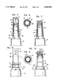
- FIG. 1 is an isometric view of a child resistant and tamper evident pierce-pak container, all in accordance with the invention.
- FIGS. 2-4 are sequential isometric views illustrating the method of use of the present invention in order to release the medicament contained within the sealed tube.
- FIG. 5 is an enlarged, fragmentary, sectional elevational view taken along the line 5,5 of FIG. 1, illustrating details of construction and assembly.
- FIG. 6 is a fragmentary, sectional elevational view taken on the line 6,6 of FIG. 5, illustrating additional details of the tear-off skirt.
- FIG. 7 is an enlarged, fragmentary, sectional elevational view taken along the line 7,7 of FIG. 3.
- FIG. 8 is an enlarged, fragmentary, elevational view with a portion broken away and in section, showing another embodiment of the invention.
- FIG. 9 is a fragmentary sectional, plan view taken on the line 9,9 of FIG. 8.
- FIG. 10 is a fragmentary, elevational view of the embodiment of FIG. 8, with a portion broken away and in section.
- FIG. 11 is an enlarged, fragmentary, sectional elevational view of another embodiment which is different from the embodiment shown in FIG. 1, again illustrating details of construction and assembly.
- FIG. 12 is a plan view taken on the line 12,12 of FIG. 11.
- FIG. 13 is an enlarged, fragmentary, sectional elevational view of the embodiment shown in FIG. 11, In an activation mode.
- FIGS. 14-16 are sequential isometric views illustrating the method of use of another embodiment of the invention shown in FIG. 1, showing the steps needed in order to release the medicament contained within the sealed tube.
- FIG. 17 is an enlarged, fragmentary, sectional elevational view taken along line 17, 17 of FIG. 14 illustrating details of construction and assembly.
- FIG. 18 is an enlarged, sectional, plan view taken on the line 18, 18 of FIG. 17.
- FIG. 19 is an enlarged, fragmentary, sectional elevational view of the embodiment shown in FIG. 17, in an activation mode.
- FIG. 20 is a sectional, plan view taken on the line 20,20 of FIG. 19.
- the assembly of this invention is shown generally by the reference number 10.
- the assembly includes a tube 13 and cap 15 which is positioned on the discharge or terminal end portion 17 of tube 13. Movement of the cap 15 in the direction of the arrow 19, as shown in FIG. 3, engages a part of the device, described herein below, which provides access to the contents of the tube 13. Movement of cap 15 in the direction of arrow 2 1 in FIG. 4 removes the cap 15 and allows the contents of the tube to be dispensed.
- vitamins, eye drops, and unit dose medicaments are contained in tube and cap assemblies of this type.
- a skirt 23 having a pull tab 25 is located on the tube engaging end of cap 15. This skirt 23 rests on shoulder 27 of tube 13 so that further movement of the cap, such as in the direction of arrow 19 is not possible as long as skirt 23 is still on the cap. Intentional manipulation to remove the skirt 23 by pulling pull tab 25, as illustrated in FIG. 2, places the assembly in a ready to use condition.
- FIGS. 5, 6 and 7, the internal working of the assembly can be seen.
- the device is as shown in FIG. 1 and the skirt 23 abuts shoulder 27 to prevent movement of the cap 15 in the tube engaging direction.
- the edge 25a of pull tab 25 is accessible and the pull tab 25 can be removed easily. This intentional manipulation is necessary for use of the tube.
- Piercer 29 is mounted on the inside of end wall 31 of cap 15, and is held in a first position as illustrated in FIG. 5. As long as skirt 23 is present, piercer 29 cannot contact thin wall section 33 of tip 35 of tube end portion 17.
- a ring 37 and groove 39 which serves as a secondary restraint to prevent unintentional movement of the cap toward the tube.
- the puncture means or piercer 29 is able to penetrate thin wall section 33, allowing for access to the contents after the cap 15 is removed from the tube end portion 17.
- FIGS. 8, 9 and 10 A similar assembly is shown in FIGS. 8, 9 and 10, in which a modification of the skirt previously described is shown.
- Split skirt 41 restrains movement of cap 15' toward tube 13 because it cannot move past shoulder 27.
- intentional manipulation of the assembly to open the tube requires that the cap 15' be pushed axially toward the tube 13 so that split skirt 41 impinges on shoulder 27 in the direction of arrow 43. If sufficient pressure is applied, split skirt 41 splits along a frangible portion, such as produced by score lines, and breaks into two portions 41a and 41b. Once the skirt 41 has split, cap 15' can be moved to cause piercer 29 to puncture thin wall section 33 as previously described.
- FIGS. 11, 12 and 13 another assembly according to the present invention is shown.
- This assembly includes a modified cap 45 which has a first end 45a and second end 45b separated by dividing wall 47.
- Piercer 29 is mounted on dividing wall 47 and is facing away from thin wall section 33 of end 35 of tube end portion 17. Piercer 29 is sterilized and kept sanitary by a closure member, shown in FIG. 11 in the form of tear-off tape 49. Tear-off tape 49 seals the end 45b of cap 45 and can be removed when needed by pulling tab 51 on tear-off tape 49.
- cap 45 which has been held in place by ring 37 and groove 39, is removed from tube end portion 17, the cap 45 is inverted, the tear-off tape 49 is removed by pulling tab 51, and the end 45b of cap 45 is placed in a second position, shown in FIG. 13, where piercer 29 once again punctures thin wall section 33 to provide access to the tube contents.
- FIGS. 14-20 A preferred embodiment is shown in FIGS. 14-20.
- the cap 53 is prevented from moving toward tube 55 by a boss 57 which is part of tube end portion 59.
- the lower terminal end 53a of cap 53 can not move past boss 57, and thus the cap 53 is maintained in its first position, where access to the contents is prevented.
- Intentional manipulation of cap 53 to bring socket 61 into alignment with boss 57, as illustrated in FIG. 15 allows cap to slide on tube end portion 59 to a second position shown in FIG. 19.
- cap 53 When the lower terminal end 53a of cap 53 is in contact with boss 57, as shown in FIG. 17, the cap 53 is held in a first position where piercer 29 is spaced from thin wall section 33. Rotation of cap 53 to align boss 57 and socket 61, as shown in FIGS. 19 and 20, allows cap 53 to be pushed in the direction of arrow 63 to provide access to the the tube contents. Without the intentional manipulation of the cap 53 from the safe position of FIG. 17 to the ready position of FIG. 19, the assembly is at least child resistant. Casual playing is not likely to cause the needed alignment. When such alignment is desired, pressure on boss 57 and the outside of socket 61 allows the two components to be rotated with respect to each other to achieve a ready to use condition.
Abstract
Description
Claims (1)
Priority Applications (1)
| Application Number | Priority Date | Filing Date | Title |
|---|---|---|---|
| US08/185,401 US5419459A (en) | 1992-01-31 | 1994-01-24 | Child resistant medicament dispenser |
Applications Claiming Priority (2)
| Application Number | Priority Date | Filing Date | Title |
|---|---|---|---|
| US07/830,308 US5301837A (en) | 1992-01-31 | 1992-01-31 | Child resistant medicament dispenser |
| US08/185,401 US5419459A (en) | 1992-01-31 | 1994-01-24 | Child resistant medicament dispenser |
Related Parent Applications (1)
| Application Number | Title | Priority Date | Filing Date |
|---|---|---|---|
| US07/830,308 Division US5301837A (en) | 1991-10-24 | 1992-01-31 | Child resistant medicament dispenser |
Publications (1)
| Publication Number | Publication Date |
|---|---|
| US5419459A true US5419459A (en) | 1995-05-30 |
Family
ID=25256721
Family Applications (2)
| Application Number | Title | Priority Date | Filing Date |
|---|---|---|---|
| US07/830,308 Expired - Fee Related US5301837A (en) | 1991-10-24 | 1992-01-31 | Child resistant medicament dispenser |
| US08/185,401 Expired - Lifetime US5419459A (en) | 1992-01-31 | 1994-01-24 | Child resistant medicament dispenser |
Family Applications Before (1)
| Application Number | Title | Priority Date | Filing Date |
|---|---|---|---|
| US07/830,308 Expired - Fee Related US5301837A (en) | 1991-10-24 | 1992-01-31 | Child resistant medicament dispenser |
Country Status (1)
| Country | Link |
|---|---|
| US (2) | US5301837A (en) |
Cited By (9)
| Publication number | Priority date | Publication date | Assignee | Title |
|---|---|---|---|---|
| US5934457A (en) * | 1995-05-29 | 1999-08-10 | Pentel Kabushiki Kaisha | Liquid container |
| WO2000061457A1 (en) * | 1999-04-12 | 2000-10-19 | Kettenbach Gmbh & Co. Kg | Film packaging for a paste-like substance |
| EP1065153A1 (en) * | 1999-07-02 | 2001-01-03 | Kettenbach GmbH & CO. KG | Foil package for pasty product |
| EP1186544A1 (en) * | 2000-09-08 | 2002-03-13 | L'oreal | Device for storing separately and extemporaneously dispensing two products |
| US6474508B1 (en) | 2002-01-24 | 2002-11-05 | Saint-Gobain Calmar Inc. | Unit dose tube and cap assembly |
| US20040040989A1 (en) * | 2002-08-28 | 2004-03-04 | Eastman Kodak Company | Dispensing method utilizing disposable coverings that prevents spread of disease through cross-contamination |
| US20050051572A1 (en) * | 2003-09-05 | 2005-03-10 | Vogel James E. | Blow fill sealed container with twist off top operated by overcap and method of forming the same |
| US20080073348A1 (en) * | 2006-09-27 | 2008-03-27 | Daniel PRITIKIN | Container closure assembly |
| US7427005B1 (en) | 2002-11-27 | 2008-09-23 | Owens-Illinois Closure Inc. | Dispensing closure, package and method of assembly with film seal piercing |
Families Citing this family (12)
| Publication number | Priority date | Publication date | Assignee | Title |
|---|---|---|---|---|
| US5301837A (en) * | 1992-01-31 | 1994-04-12 | Cp Packaging, Inc. | Child resistant medicament dispenser |
| US6379069B1 (en) | 1994-12-12 | 2002-04-30 | James Alexander Corporation | Dispenser and process |
| US5590780A (en) * | 1995-06-22 | 1997-01-07 | Wheaton Holding, Inc. | Unit dose assembly |
| US6126037A (en) * | 1997-09-09 | 2000-10-03 | Merck & Co., Inc. | Flow control orifice |
| EP1748930A4 (en) * | 2004-03-29 | 2012-05-02 | Merial Ltd | Pipette/applicator |
| US20050111900A1 (en) * | 2004-11-30 | 2005-05-26 | Francesca Fazzolari | Ampoule and method of use |
| US7581899B2 (en) * | 2004-11-30 | 2009-09-01 | James Alexander Corporation | Dispenser and process |
| US7976234B2 (en) | 2006-04-28 | 2011-07-12 | James Alexander Corporation | Multi-chambered dispenser and process |
| ITMO20060192A1 (en) * | 2006-06-16 | 2007-12-17 | Lameplast Spa | PERFECTED BOTTLE FOR FLUID, PARTICULARLY PHARMACEUTICAL, MEDICINAL OR COSMETIC PRODUCTS |
| IT1391454B1 (en) * | 2008-09-26 | 2011-12-23 | Lameplast Spa | CONTAINER FOR FLUID, PARTICULARLY PHARMACEUTICAL, COSMETIC, FOOD OR SIMILAR PRODUCTS |
| FR3033319B1 (en) * | 2015-03-05 | 2019-06-21 | Eskiss Packaging | CONTAINER FOR RECEIVING A DETERMINED DOSE OF AT LEAST TWO PRODUCTS OF THE SAME NATURE OR OF DIFFERENT NATURE |
| US9821936B1 (en) * | 2015-08-12 | 2017-11-21 | Huitzilo Arriaga | Bottle cap with integrated bottle opener |
Citations (6)
| Publication number | Priority date | Publication date | Assignee | Title |
|---|---|---|---|---|
| US1909209A (en) * | 1932-07-16 | 1933-05-16 | Lilly Co Eli | Closure for collapsible tubes |
| US2365524A (en) * | 1942-05-25 | 1944-12-19 | Gelatin Products Corp | Dispensing capsule |
| US4346820A (en) * | 1979-05-02 | 1982-08-31 | Sigma-Tau Industrie Farmaceutiche Riunite | Apparatus for mixing and dispersing two substances under sterile conditions |
| US4867326A (en) * | 1988-08-25 | 1989-09-19 | Cp Packaging | Child resistant cap and tube assembly |
| WO1991012198A1 (en) * | 1990-02-08 | 1991-08-22 | Cp Packaging, Inc. | Unit dose assembly |
| US5301837A (en) * | 1992-01-31 | 1994-04-12 | Cp Packaging, Inc. | Child resistant medicament dispenser |
Family Cites Families (2)
| Publication number | Priority date | Publication date | Assignee | Title |
|---|---|---|---|---|
| US3109562A (en) * | 1954-09-07 | 1963-11-05 | Schering Corp | Nozzle perforating cap for collapsible tubes |
| US4458820A (en) * | 1983-02-14 | 1984-07-10 | Martin Abrams | Tamper-indicating arrangement for a container |
-
1992
- 1992-01-31 US US07/830,308 patent/US5301837A/en not_active Expired - Fee Related
-
1994
- 1994-01-24 US US08/185,401 patent/US5419459A/en not_active Expired - Lifetime
Patent Citations (6)
| Publication number | Priority date | Publication date | Assignee | Title |
|---|---|---|---|---|
| US1909209A (en) * | 1932-07-16 | 1933-05-16 | Lilly Co Eli | Closure for collapsible tubes |
| US2365524A (en) * | 1942-05-25 | 1944-12-19 | Gelatin Products Corp | Dispensing capsule |
| US4346820A (en) * | 1979-05-02 | 1982-08-31 | Sigma-Tau Industrie Farmaceutiche Riunite | Apparatus for mixing and dispersing two substances under sterile conditions |
| US4867326A (en) * | 1988-08-25 | 1989-09-19 | Cp Packaging | Child resistant cap and tube assembly |
| WO1991012198A1 (en) * | 1990-02-08 | 1991-08-22 | Cp Packaging, Inc. | Unit dose assembly |
| US5301837A (en) * | 1992-01-31 | 1994-04-12 | Cp Packaging, Inc. | Child resistant medicament dispenser |
Cited By (16)
| Publication number | Priority date | Publication date | Assignee | Title |
|---|---|---|---|---|
| US5934457A (en) * | 1995-05-29 | 1999-08-10 | Pentel Kabushiki Kaisha | Liquid container |
| WO2000061457A1 (en) * | 1999-04-12 | 2000-10-19 | Kettenbach Gmbh & Co. Kg | Film packaging for a paste-like substance |
| EP1065153A1 (en) * | 1999-07-02 | 2001-01-03 | Kettenbach GmbH & CO. KG | Foil package for pasty product |
| EP1186544A1 (en) * | 2000-09-08 | 2002-03-13 | L'oreal | Device for storing separately and extemporaneously dispensing two products |
| FR2813869A1 (en) * | 2000-09-08 | 2002-03-15 | Oreal | DEVICE FOR THE SEPARATE PACKAGING AND THE JOINT OUTPUT OF TWO EXTEMPORANEOUSLY MIXED PRODUCTS |
| US6609634B2 (en) | 2000-09-08 | 2003-08-26 | L'oreal S.A. | Dispensing device and methods |
| US6474508B1 (en) | 2002-01-24 | 2002-11-05 | Saint-Gobain Calmar Inc. | Unit dose tube and cap assembly |
| US20040040989A1 (en) * | 2002-08-28 | 2004-03-04 | Eastman Kodak Company | Dispensing method utilizing disposable coverings that prevents spread of disease through cross-contamination |
| US7427005B1 (en) | 2002-11-27 | 2008-09-23 | Owens-Illinois Closure Inc. | Dispensing closure, package and method of assembly with film seal piercing |
| US20050051572A1 (en) * | 2003-09-05 | 2005-03-10 | Vogel James E. | Blow fill sealed container with twist off top operated by overcap and method of forming the same |
| US7188750B2 (en) * | 2003-09-05 | 2007-03-13 | Hospira, Inc. | Blow fill sealed container with twist off top operated by overcap and method of forming the same |
| US20070095855A1 (en) * | 2003-09-05 | 2007-05-03 | Hospira, Inc. | Blow fill sealed container with twist off top operated by overcap and method of making the same |
| US20070095856A1 (en) * | 2003-09-05 | 2007-05-03 | Hospira, Inc | Blow fill sealed container with twist off top operated by overcap and method of making the same |
| JP2007503919A (en) * | 2003-09-05 | 2007-03-01 | ホスピラ・インコーポレイテツド | Blowfill sealed container having a torsion top operated by an overcap and method of forming the same |
| US20080073348A1 (en) * | 2006-09-27 | 2008-03-27 | Daniel PRITIKIN | Container closure assembly |
| US7591398B2 (en) * | 2006-09-27 | 2009-09-22 | Pouchsmart, Inc. | Container closure assembly |
Also Published As
| Publication number | Publication date |
|---|---|
| US5301837A (en) | 1994-04-12 |
Similar Documents
| Publication | Publication Date | Title |
|---|---|---|
| US5419459A (en) | Child resistant medicament dispenser | |
| US4867326A (en) | Child resistant cap and tube assembly | |
| US4307821A (en) | Container-closure assembly | |
| US4538740A (en) | Tamper resistant closure | |
| US5040691A (en) | Child-resistant, easy opening package | |
| US4711372A (en) | Tamper indicating closure | |
| USRE39867E1 (en) | Tamper-evident container closure | |
| US5228593A (en) | Container-closure assembly | |
| EP0513229B1 (en) | Unit dose assembly | |
| US5092493A (en) | Captive key release closure structure | |
| US4712705A (en) | Tamper indicating cap seal for container valves | |
| US4595123A (en) | Tamper evident closure cap | |
| US5383564A (en) | Adult friendly child-resistant attachment for containers used to store potentially dangerous materials | |
| US5685444A (en) | Tamper-evident hinged closure cap construction | |
| EP0113550B1 (en) | A tamper-resistant and child-resistant closure | |
| US4534481A (en) | Snap-on, tamper-evident container closure | |
| US5111947A (en) | Tamper proof cap and container | |
| US7540389B2 (en) | Bottle for fluid products, particularly pharmaceutical, medicinal and cosmetic products | |
| US4432462A (en) | Receptacle tampering indicator and method therefor | |
| CA1291448C (en) | Tamper-resistant pharmaceutical vial and cap assembly | |
| US5423441A (en) | Closure system for a container and cap | |
| AU2012266372A1 (en) | Stopping device and container comprising such a device | |
| EP2452890B1 (en) | Upgraded bottle for fluid products, particularly pharmaceutical, medicinal or cosmetic products | |
| USRE40003E1 (en) | Tamper-evident container closure | |
| US4991730A (en) | Captive key release closure structure |
Legal Events
| Date | Code | Title | Description |
|---|---|---|---|
| AS | Assignment |
Owner name: WHEATON INDUSTRIES, INC., NEW JERSEY Free format text: CHANGE OF NAME;ASSIGNOR:C P PACKAGING, INC.;REEL/FRAME:007289/0329 Effective date: 19931229 Owner name: WHEATON HOLDING, INC., DELAWARE Free format text: ASSIGNMENT OF ASSIGNORS INTEREST;ASSIGNOR:WHEATON INDUSTRIES, INC.;REEL/FRAME:007289/0336 Effective date: 19941207 |
|
| STCF | Information on status: patent grant |
Free format text: PATENTED CASE |
|
| AS | Assignment |
Owner name: WHEATON INC., NEW JERSEY Free format text: MERGER;ASSIGNOR:WHEATON HOLDING, INC.;REEL/FRAME:007629/0195 Effective date: 19950616 |
|
| CC | Certificate of correction | ||
| FPAY | Fee payment |
Year of fee payment: 4 |
|
| FPAY | Fee payment |
Year of fee payment: 8 |
|
| FPAY | Fee payment |
Year of fee payment: 12 |
|
| AS | Assignment |
Owner name: GLAS TRUST CORPORATION LIMITED, AS SECURITY AGENT, Free format text: SECURITY INTEREST;ASSIGNORS:DURAN, INC.;WHEATON INDUSTRIES, INC.;REEL/FRAME:041835/0477 Effective date: 20170330 |