US5419606A - Trim panel attaching pin with water seal - Google Patents
Trim panel attaching pin with water seal Download PDFInfo
- Publication number
- US5419606A US5419606A US08/172,772 US17277293A US5419606A US 5419606 A US5419606 A US 5419606A US 17277293 A US17277293 A US 17277293A US 5419606 A US5419606 A US 5419606A
- Authority
- US
- United States
- Prior art keywords
- panel
- inner door
- shaft
- holes
- door panel
- Prior art date
- Legal status (The legal status is an assumption and is not a legal conclusion. Google has not performed a legal analysis and makes no representation as to the accuracy of the status listed.)
- Expired - Lifetime
Links
Images


Classifications
-
- B—PERFORMING OPERATIONS; TRANSPORTING
- B60—VEHICLES IN GENERAL
- B60R—VEHICLES, VEHICLE FITTINGS, OR VEHICLE PARTS, NOT OTHERWISE PROVIDED FOR
- B60R13/00—Elements for body-finishing, identifying, or decorating; Arrangements or adaptations for advertising purposes
- B60R13/02—Internal Trim mouldings ; Internal Ledges; Wall liners for passenger compartments; Roof liners
- B60R13/0206—Arrangements of fasteners and clips specially adapted for attaching inner vehicle liners or mouldings
-
- Y—GENERAL TAGGING OF NEW TECHNOLOGICAL DEVELOPMENTS; GENERAL TAGGING OF CROSS-SECTIONAL TECHNOLOGIES SPANNING OVER SEVERAL SECTIONS OF THE IPC; TECHNICAL SUBJECTS COVERED BY FORMER USPC CROSS-REFERENCE ART COLLECTIONS [XRACs] AND DIGESTS
- Y10—TECHNICAL SUBJECTS COVERED BY FORMER USPC
- Y10S—TECHNICAL SUBJECTS COVERED BY FORMER USPC CROSS-REFERENCE ART COLLECTIONS [XRACs] AND DIGESTS
- Y10S24/00—Buckles, buttons, clasps
- Y10S24/30—Separable-fastener or required component thereof
- Y10S24/31—Separable-fastener or required component thereof with third, detached member completing interlock
- Y10S24/32—And linking cavities in adjacent parallel panels
-
- Y—GENERAL TAGGING OF NEW TECHNOLOGICAL DEVELOPMENTS; GENERAL TAGGING OF CROSS-SECTIONAL TECHNOLOGIES SPANNING OVER SEVERAL SECTIONS OF THE IPC; TECHNICAL SUBJECTS COVERED BY FORMER USPC CROSS-REFERENCE ART COLLECTIONS [XRACs] AND DIGESTS
- Y10—TECHNICAL SUBJECTS COVERED BY FORMER USPC
- Y10T—TECHNICAL SUBJECTS COVERED BY FORMER US CLASSIFICATION
- Y10T24/00—Buckles, buttons, clasps, etc.
- Y10T24/30—Trim molding fastener
- Y10T24/309—Plastic type
-
- Y—GENERAL TAGGING OF NEW TECHNOLOGICAL DEVELOPMENTS; GENERAL TAGGING OF CROSS-SECTIONAL TECHNOLOGIES SPANNING OVER SEVERAL SECTIONS OF THE IPC; TECHNICAL SUBJECTS COVERED BY FORMER USPC CROSS-REFERENCE ART COLLECTIONS [XRACs] AND DIGESTS
- Y10—TECHNICAL SUBJECTS COVERED BY FORMER USPC
- Y10T—TECHNICAL SUBJECTS COVERED BY FORMER US CLASSIFICATION
- Y10T24/00—Buckles, buttons, clasps, etc.
- Y10T24/45—Separable-fastener or required component thereof [e.g., projection and cavity to complete interlock]
- Y10T24/45005—Separable-fastener or required component thereof [e.g., projection and cavity to complete interlock] with third detached member completing interlock [e.g., hook type]
- Y10T24/45099—Resilient element [e.g., snap type]
- Y10T24/45105—Resilient element [e.g., snap type] for upholstery, panel, trim strip, etc. [e.g., spring biased]
Definitions
- the present invention relates to automotive door trim panel assemblies, and, more particularly, to a retaining pin having energy absorption and moisture prevention features for attaching a vehicle interior trim panel to an inner door panel.
- Vehicle doors are typically constructed with two or more panels attached to the door frame, including an exterior panel for shielding the passenger compartment from the elements, an inner door panel which provides structural support, and a trim panel facing the passenger compartment.
- the trim panel is usually fastened to the inner door panel and shields the vehicle occupants from the door internal components, such as the window, the window regulator, and the door locks.
- Foam may be placed between the inner door panel and the trim panel to absorb energy from excessive side loading of the vehicle as in the impact loading attendant a collision, as is disclosed in U.S. Pat. No. 4,890,877 (Ashtiani-Zarandi et al.). Energy absorption is also accomplished by mounting steel straps behind the trim panel, as shown in U.S. Pat. No. 5,048,234 (Lau et al.).
- the present invention provides an automotive door interior assembly comprising an inner door panel, an interior trim panel, and retaining means for retaining the trim panel to the inner door panel.
- the retaining means has panel locating means for aligning the retaining means with connection means in the inner door panel, moisture barrier means for preventing moisture seepage through the inner door panel to a space between the trim panel and the inner door panel, and shear means attached to the retaining means for absorbing energy upon movement of the retaining means through the connection means.
- the connection means preferably comprises holes which shear the shear means from the retaining means upon movement through the holes.
- the retaining means comprises a plurality of pins having a shaft with a first end having a plurality of spaced apart longitudinal splines attached thereto.
- the pins also have a second end with panel locating means attached thereto, with the locating means comprising a spear shaped nose section pointing in a direction away from the first end along an axis through the shaft.
- the nose section assists in locating the holes during panel assembly.
- the nose section has of a plurality of spaced apart finger members attached thereto which also provide panel retention and energy absorption functions.
- the finger members extend generally toward the first end and are angled away from the shaft such that the distance between finger members on opposite sides of said shaft is greater than the diameter of the hole.
- the finger members compress toward the shaft as the nose section is pushed through the holes and flex away from the shaft after passing through a hole to prevent retraction of the pin therefrom.
- the holes shear or deform the finger members upon separation of the inner door panel from the trim panel, for example, during a side impact.
- the moisture barrier means comprises an umbrella shaped water seal attached to the shaft adjacent to the nose section near the second end of the shaft.
- the seal has a concave side facing the nose section and a diameter greater than the holes, with the concave side abutting the inner door panel so as to cover the holes.
- the seal cooperates with the finger members to secure the inner door panel therebetween thus connecting the pin to the inner door panel.
- the shaft, the said water seal, the nose section, the finger members, and the splines are integrally molded as a single retaining pin from a thermoplastic material.
- the preferred embodiment has an inner door panel with a reinforcing panel connected thereto on a side opposite the trim panel, with the reinforcing panel having a plurality of openings for receiving the retaining pin upon movement of the trim panel toward the inner door panel.
- FIG. 1 is an interior view of an automobile passenger compartment showing an inner door panel assembly according to the present invention as attached to the vehicle.
- FIG. 2 is a cross-sectional view along line 2--2 of FIG. 1 showing a trim panel connected to an inner door panel by a retaining pin according to the present invention.
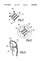
- FIG. 3 is a cross-sectional view of a retaining pin according to the present invention along line 3--3 of FIG. 2 showing the pin shaft and spaced apart splines.
- FIG. 4 is a view through a hole in the inner door panel of the panel assembly according to the present invention showing a retaining pin in cross-section with splines partially sheared off as it would appear when moving through the hole to absorb energy.
- FIG. 5 is a cross-sectional view of a door panel assembly according to the present invention showing a trim panel having a retaining pin rigidly attached thereto and connected to an inner door panel.
- FIG. 6 is a cross-sectional view of a door panel assembly according to the present invention shown under compression with the retaining pin pushed through a connection hole in the inner door panel such that the splines are sheared from the pin shaft to absorb energy.
- FIG. 7 is a cross-sectional view of a door panel assembly according to the present invention under compression showing an extrusion opening in a reinforcement panel receiving the retaining pin nose section.
- FIG. 8 is a side view of a retaining pin according to the present invention showing deformation of the finger members of the nose section after the pin has been partially retracted through the connection hole due to separation of the trim panel from the inner door panel.
- FIG. 1 a partial interior view of passenger compartment 10 of an automobile is shown with a front door 12 having an inner door panel assembly 14 including a trim panel 16 facing the interior of passenger compartment 10.
- the door panel assembly of the present invention can be used for doors regardless of location on a vehicle, including but not limited to rear doors and tailgate doors, as well as fixed interior structural elements, such as interior trim covers.
- FIG. 2 a cross-section of inner door panel assembly 14 is shown with retaining means, preferably retaining pin 18, for connecting trim panel 16 with inner door panel 20.
- Trim panel 16 which may be molded from polyurethane or other foam materials known to those skilled in the art, has mold cavity 22 for placement of receptacle ring 28 to which pin 18 attaches.
- Receptacle ring 28 has a cap 24 which is placed within trim panel 16 to prevent foam from entering space 26 during molding.
- Ring 28 is also molded into trim panel 16 for receiving base 30 of pin 18.
- Base 30 has annular groove 32 into which ring 28 fits to attach pin 18 to trim panel 16.
- pin 18 has shaft 34 with shear means attached thereto, preferably longitudinal spaced apart splines 36, axially adjacent to base 30. Splines 36 absorb energy when sheared from shaft 34, as is further described below. Additionally, pin 18 has panel locating means 38 carried thereon at an end of shaft 34 opposite base 30 for directing pin 18 through a hole 40 of inner door panel 14 for attachment of trim panel 16 and inner door panel 14 during assembly of the automobile. Locating means 38 preferably comprises a spear shaped nose section pointing in a direction away from base 30 along an axis through the length of shaft 34.
- Locating means 38 also has of a plurality of spaced apart finger members 42, or retrorse fins, attached thereto extending generally toward base 30 and angled away from shaft 34 such that the distance between finger members 42 on opposite sides of shaft 34 is greater than the diameter of hole 40 (FIG. 2).
- finger members 42 When locating means 38 is pushed into hole 40, finger members 42 are compressed toward shaft 34 to allow pin 18 to pass through. After locating means 38 have passed through hole 40, finger members 42 spring back to the spear shaped position to prevent retraction of pin 18 from hole 40.
- finger members 42 have undercut portions 44 which begin at a point 46 where finger members 42 are furthest away from shaft 34. Undercut portions 44 are angled toward shaft 34 for locking against inner surface 48 of hole 40 to prevent pin 18 from retracting therefrom.
- moisture barrier means preferably comprising an umbrella shaped water seal 50, is carried with shaft 34 adjacent to finger extensions 52.
- Finger extensions 52 extend toward base 30 approximately parallel to shaft 34 from undercut portions 44 and serve to position and support water seal 50 as well as hold undercut portions 44 in place against hole inner surface 48.
- Water seal 50 has a concave side 54 with a diameter greater than hole 40 to prevent moisture from seeping into space 57 between inner door panel 20 and trim panel 16 through hole 40. Concave side 54 abuts inner door panel 20 so as to cover hole 40. Water seal 50 also cooperates with undercut portions 44 of finger members 42 to clamp pin 18 to inner door panel 20.
- FIG. 3 A cross-sectional view through the preferred embodiment of pin 18 is shown in FIG. 3.
- Shaft 34 has splines 36 on a radially outermost surface 56 thereof which are circumferentially spaced apart 90°.
- Spline tips 58 shown rounded, can have any geometric shape.
- FIG. 4 shows pin 18 in cross-section with spline tips 58 sheared off as a result of movement through inner surface 48 of hole 40 since the distance between spline tips 58 on opposite sides of shaft 34 is greater than the diameter of hole 40.
- the number of splines 36 on shaft 34 as well as the size of splines 36 relative to the diameter of hole 40 affect the energy absorbed by pin 18 as it moves through hole 40.
- inner door panel assembly 14 of the present invention converts the kinetic energy directed toward the passenger compartment 10, which results due to movement of pin 18 relative to inner door panel 20, to heat energy through shearing of splines 36 as pin 18 is forced through hole 40.
- the sequence of FIGS. 5, 6, and 7 depicts such an energy conversion when a portion of panel assembly 14 undergoes compression, for example, during a side door 12 impact or when an occupant of the vehicle strikes panel assembly 14.
- FIG. 5 shows a cross-sectional view of an assembled door panel assembly 14 according to the present invention with pin 18 connecting trim panel 16 to inner door panel 20 as described above.
- a reinforcing panel 60 is attached to inner door panel 20 on a side opposite trim panel 16.
- An opening hole 62 is formed in reinforcing panel 60 and aligned with hole 40 and receptacle 22 for receiving pin 18 upon movement of trim panel 16 toward inner door panel 20 when panel assembly 14 is under compression (FIG. 6).
- Splines 36 are sheared from shaft 34 as pin 18 moves through hole 40 (FIG. 7).
- a plurality of spaced apart pins 18 are attached to trim panel 16 by a plurality of receptacles 22, with the plurality of pins 18 connected to a plurality of spaced apart holes 40 in inner door panel 20 aligned with the plurality of pins 18 along an axis through holes 40 and perpendicular to inner door panel 20 when trim panel 16 is aligned for attachment therewith.
- shaft 34, base 30, water seal 50, locating means 38, finger members 42, and splines 36 are integrally molded as a single retaining pin 18 from a thermoplastic material, such as acetyl, or other plastic or non-plastic materials known to those skilled in the art and suggested by this disclosure.
Abstract
Description
Claims (14)
Priority Applications (3)
| Application Number | Priority Date | Filing Date | Title |
|---|---|---|---|
| US08/172,772 US5419606A (en) | 1993-12-27 | 1993-12-27 | Trim panel attaching pin with water seal |
| DE4438309A DE4438309C2 (en) | 1993-12-27 | 1994-10-26 | Motor vehicle door trim assembly |
| JP6280710A JPH07205656A (en) | 1993-12-27 | 1994-11-15 | Watertight decorative panel mounting pin |
Applications Claiming Priority (1)
| Application Number | Priority Date | Filing Date | Title |
|---|---|---|---|
| US08/172,772 US5419606A (en) | 1993-12-27 | 1993-12-27 | Trim panel attaching pin with water seal |
Publications (1)
| Publication Number | Publication Date |
|---|---|
| US5419606A true US5419606A (en) | 1995-05-30 |
Family
ID=22629166
Family Applications (1)
| Application Number | Title | Priority Date | Filing Date |
|---|---|---|---|
| US08/172,772 Expired - Lifetime US5419606A (en) | 1993-12-27 | 1993-12-27 | Trim panel attaching pin with water seal |
Country Status (3)
| Country | Link |
|---|---|
| US (1) | US5419606A (en) |
| JP (1) | JPH07205656A (en) |
| DE (1) | DE4438309C2 (en) |
Cited By (61)
| Publication number | Priority date | Publication date | Assignee | Title |
|---|---|---|---|---|
| GB2304648A (en) * | 1995-09-06 | 1997-03-26 | Rover Group | Trim fixing |
| GB2308340A (en) * | 1995-12-19 | 1997-06-25 | Rover Group | Vehicle interior trim panel assembly with collapsible fixing means |
| EP0849123A1 (en) * | 1996-12-17 | 1998-06-24 | General Motors Corporation | Energy absorbing molding assembly |
| US5855094A (en) * | 1995-04-24 | 1999-01-05 | Ymos Aktiengesellschaft-Industrieprodukte | Motor vehicle door |
| US5857244A (en) * | 1997-07-30 | 1999-01-12 | General Motors Corporation | Fastener with molded-on compliant seal |
| EP0890750A2 (en) * | 1997-06-25 | 1999-01-13 | Emhart Inc. | Fastener with a seal |
| US5876084A (en) * | 1997-07-15 | 1999-03-02 | Prince Corporation | Panel mounting clip |
| US5927790A (en) * | 1997-06-11 | 1999-07-27 | Daimler-Benz Aktiengesellschaft | Motor vehicle instrument panel having a trim strip extending horizontally over it |
| US5934729A (en) * | 1997-03-10 | 1999-08-10 | Ford Global Technologies, Inc. | Energy-absorbing fastener system |
| US5992914A (en) * | 1995-12-27 | 1999-11-30 | Honda Giken Kogyo Kabushiki Kaisha | Trim member for vehicle |
| EP0964170A2 (en) * | 1998-06-10 | 1999-12-15 | TRW Automotive Electronics & Components GmbH & Co. KG | Fastening element between a support and a panel, especially a body element of an automotive vehicle |
| US6095593A (en) * | 1997-08-13 | 2000-08-01 | Dr. Ing. H.C.F. Porsche Ag | Energy-absorbing covering for a vehicle body column of a motor vehicle |
| US6101096A (en) * | 1999-06-10 | 2000-08-08 | Intel Corporation | Heat sink clip for an electronic assembly |
| US6145908A (en) * | 1998-05-11 | 2000-11-14 | Ford Global Technologies, Inc. | Energy absorbing continuously compliant swept arch for interior trim |
| US6196607B1 (en) * | 1999-09-09 | 2001-03-06 | Patent Holding Company | Trim panel assembly and plastic interior trim panel for use therein |
| US20010028131A1 (en) * | 1999-12-30 | 2001-10-11 | Brodi James Joseph | Method of making an interior trim panel |
| US6349987B1 (en) * | 1999-09-15 | 2002-02-26 | Eurostyle | Composite part for an automobile |
| US6406242B1 (en) * | 2000-11-10 | 2002-06-18 | Trw Inc. | Apparatus for fastening together two plates |
| US6405494B1 (en) * | 1997-09-30 | 2002-06-18 | Wolfgang Wismeth | Fixing device for solar modules |
| US6422640B2 (en) * | 1999-12-30 | 2002-07-23 | Delphi Technologies, Inc. | Door trim panel assembly and method of making |
| US6497011B2 (en) * | 2000-04-26 | 2002-12-24 | Termax Corporation | Vehicle having parts connected with a sealing spring fastener comprising a hermetically closed cavity |
| US20030093883A1 (en) * | 2001-11-21 | 2003-05-22 | Gibbons Matthew H. | Plastic retaining clip for rib attachment |
| US6594870B1 (en) | 2001-01-22 | 2003-07-22 | Johnson Controls Technology Company | Panel fastener |
| US6656397B1 (en) | 1999-03-11 | 2003-12-02 | Delphi Technologies, Inc. | Method of making a door trim assembly |
| US20030233738A1 (en) * | 2001-03-02 | 2003-12-25 | Osterland Robert W. | Low insertion effort U-base retainer |
| US6676324B1 (en) | 1998-04-06 | 2004-01-13 | Brose Fahrzeugteile Gmbh & Co. Kg | Device for fixing interior coverings in motor vehicles |
| US6723263B2 (en) | 2001-09-25 | 2004-04-20 | Delphi Technologies, Inc. | Apparatus and method of making interior trim panel |
| US20040139584A1 (en) * | 2003-01-17 | 2004-07-22 | Gibbons Matthew H. | Two-piece interior trim retainer |
| US20050072116A1 (en) * | 1997-12-19 | 2005-04-07 | Henkel Kgaa | Configuration for isolating cavities |
| US20050168009A1 (en) * | 2004-02-04 | 2005-08-04 | Lear Corporation | Wrapped bolster seal |
| US20050206193A1 (en) * | 2004-03-16 | 2005-09-22 | Sweers Michael J | Reinforced door trim panel |
| US20050253416A1 (en) * | 2004-05-12 | 2005-11-17 | Bogdan Radu | Modular automotive door trim panel construction |
| US20060000149A1 (en) * | 2004-06-30 | 2006-01-05 | Bogdan Radu | Modular vehicle door construction |
| US20060043765A1 (en) * | 2004-08-25 | 2006-03-02 | Bogdan Radu | Automotive hardware carrier and method of making same |
| US20060059784A1 (en) * | 2004-09-21 | 2006-03-23 | Eluid David Carter | Door module positioning system |
| US20060082187A1 (en) * | 2004-10-19 | 2006-04-20 | Arvinmeritor Technology, Llc | Snap pin for door module positioning |
| US20060214468A1 (en) * | 2005-03-23 | 2006-09-28 | Cass Michael W | Connector for automotive interior trim |
| US20070063539A1 (en) * | 2005-09-12 | 2007-03-22 | Dimario Joseph | Snap-in mounting clip, panel having a snap-in mounting clip, and method of mounting the panel |
| US20070293281A1 (en) * | 2006-06-15 | 2007-12-20 | Motorola, Inc. | Seal for portable electronic device housing with flex circuit |
| US20080263834A1 (en) * | 2005-12-14 | 2008-10-30 | Bridgestone Corporation | EA member, and clip and structure for securing the same |
| US20090089987A1 (en) * | 2007-10-04 | 2009-04-09 | A. Raymond Et Cie | Device for fastening an accessory to a support part |
| US20090277117A1 (en) * | 2008-05-06 | 2009-11-12 | Worthington Armstrong Venture | Suspended ceiling cloud with flexible panel |
| US20100000156A1 (en) * | 2006-08-11 | 2010-01-07 | Thomas Salhoff | Unit carrier for fitting into a door structure of a motor vehicle door |
| US20100172691A1 (en) * | 2007-07-20 | 2010-07-08 | Henkel Ag & Co. Kgaa | Molded polymeric spacing devices |
| US20110041299A1 (en) * | 2009-08-21 | 2011-02-24 | Toyoda Iron Works Co., Ltd. | Structure for fastening clip to trim board, clip, and clip fastening method |
| CN102245436A (en) * | 2008-12-11 | 2011-11-16 | Trw车辆电气与零件有限公司 | Device for fastening a vehicle interior trim panel |
| US20120187715A1 (en) * | 2011-01-21 | 2012-07-26 | GM Global Technology Operations LLC | Door assembly with anti-theft device |
| US20120248821A1 (en) * | 2009-10-28 | 2012-10-04 | Bayerische Motoren Werke Aktiengesellschaft | Flat Vehicle Body Component Made of a Carbon Fiber Reinforced Plastic |
| US20130127196A1 (en) * | 2010-06-04 | 2013-05-23 | Katsuhiko Takeuchi | Garnish and mounting structure |
| US20130240008A1 (en) * | 2012-03-16 | 2013-09-19 | Christopher Baker | System and method for mounting photovoltaic modules |
| US8590223B2 (en) | 2011-08-29 | 2013-11-26 | A. Raymond Et Cie | Solar panel assembly attachment apparatus |
| US8713881B2 (en) | 2012-01-27 | 2014-05-06 | A. Raymond Et Cie | Solar panel securing system |
| US8745935B2 (en) * | 2011-10-14 | 2014-06-10 | A. Raymond Et Cie | Photovoltaic panel fastening system |
| US8769779B2 (en) | 2011-03-24 | 2014-07-08 | Ford Global Technologies, Llc | Inertia locking hidden pushpin |
| US8894424B2 (en) | 2011-08-29 | 2014-11-25 | A. Raymond Et Cie | Universal clip apparatus for solar panel assembly |
| US8955259B2 (en) | 2011-06-09 | 2015-02-17 | A. Raymond & Cie | Solar panel attachment system for a roof |
| US9097272B2 (en) | 2010-07-06 | 2015-08-04 | Bayerische Motoren Werke Aktiengesellschaft | Fixing arrangement for fixing motor vehicle components |
| US9331629B2 (en) | 2012-07-02 | 2016-05-03 | A. Raymond Et Cie | Photovoltaic frame fastener |
| EP2455205A3 (en) * | 2010-11-22 | 2018-01-17 | EDAG GmbH & Co. KGaA | Visible component, method for producing the same as well as foaming mould for implementing the method |
| US10003113B1 (en) | 2016-12-19 | 2018-06-19 | Ford Global Technologies, Llc | Fastening assembly and method |
| US10683882B2 (en) | 2012-12-19 | 2020-06-16 | Illinois Tool Works Inc. | Push through retainer connection with integrated hinging seal |
Families Citing this family (9)
| Publication number | Priority date | Publication date | Assignee | Title |
|---|---|---|---|---|
| DE29512536U1 (en) * | 1995-08-03 | 1995-10-12 | Panduit Gmbh | Clamping element for insertion into openings in partitions or the like. |
| DE19532360A1 (en) * | 1995-09-01 | 1997-03-06 | Bayerische Motoren Werke Ag | Element to fasten panelling to supporting component, especially on car |
| DE19718148A1 (en) * | 1997-04-30 | 1998-11-05 | Modus Product Design Gmbh | Pin type member for connecting at least two flat elements |
| DE10000383B4 (en) * | 2000-01-07 | 2017-03-09 | Volkswagen Ag | Device for attaching an interior trim to the door of a motor vehicle |
| DE10200884B4 (en) * | 2002-01-11 | 2017-06-08 | Volkswagen Ag | Fastening device for a trim part of a vehicle, in particular a motor vehicle |
| DE102009026727A1 (en) | 2009-06-04 | 2010-12-09 | Lisa Dräxlmaier GmbH | Fastening device for releasable connection of body trim e.g. decorative strip, with base support i.e. door, of motor vehicle, has latching element arranged at body trim, and locking element for supporting connection of trim and base support |
| DE102009043129A1 (en) | 2009-09-25 | 2011-03-31 | Volkswagen Ag | Arrangement for fastening door lining to support structure of door of passenger car, has profile section with smaller hollow profile transverse section, penetrated into another profile section with larger hollow profile transverse section |
| JP5983511B2 (en) * | 2013-04-11 | 2016-08-31 | トヨタ紡織株式会社 | Positioning structure for vehicle interior materials |
| JP6585015B2 (en) * | 2016-07-25 | 2019-10-02 | トヨタ紡織株式会社 | Interior materials for vehicles |
Citations (17)
| Publication number | Priority date | Publication date | Assignee | Title |
|---|---|---|---|---|
| US3733655A (en) * | 1971-11-03 | 1973-05-22 | R Kolibar | Fastener device |
| US3778958A (en) * | 1970-01-30 | 1973-12-18 | British Leyland Truck & Bus | Panel spacing and holding clip |
| US4122583A (en) * | 1977-04-23 | 1978-10-31 | Ford Motor Company | Fastening clips for trim panels particularly for motor vehicles |
| US4505611A (en) * | 1982-02-26 | 1985-03-19 | Kasai Kogyo Co., Ltd. | Upholstery fixing device |
| US4629356A (en) * | 1982-07-14 | 1986-12-16 | Kitagawa Industries Co., Ltd. | Securing unit |
| US4786225A (en) * | 1981-12-14 | 1988-11-22 | Hartwell Corporation | Stand-off fastener |
| US4890877A (en) * | 1988-07-12 | 1990-01-02 | General Motors Corporation | Energy absorption system for vehicle door and method of making |
| JPH02231246A (en) * | 1989-03-03 | 1990-09-13 | Mazda Motor Corp | Energy absorbing device for vehicle |
| US5039160A (en) * | 1989-07-05 | 1991-08-13 | Austria Metall Aktiengesellschaft | Side-collision protective beam for motor vehicle |
| US5048234A (en) * | 1990-12-24 | 1991-09-17 | General Motors Corporation | Energy absorbing modular door |
| US5056199A (en) * | 1990-02-02 | 1991-10-15 | General Motors Corporation | Plastic fastener to attach door trim panel |
| US5083832A (en) * | 1989-07-12 | 1992-01-28 | Mazda Motor Corporation | Structure of vehicle door |
| US5090755A (en) * | 1990-06-25 | 1992-02-25 | Austria Metall Aktiengesellschaft | Impact absorber, especially as a vehicle bumper support |
| US5106223A (en) * | 1990-05-07 | 1992-04-21 | Trw United-Carr Gmbh Co., K.G. | Connection assembly for use between a support and a plate element |
| US5169204A (en) * | 1992-04-08 | 1992-12-08 | Davidson Textron Inc. | Energy absorbing inner door panel with fasteners to absorb body impact energy |
| US5173026A (en) * | 1991-02-22 | 1992-12-22 | Itw De France | Clip having peripheral sealing |
| US5362102A (en) * | 1992-09-14 | 1994-11-08 | Volkswagen Ag | Support arrangement for supporting a trim member from a structural member of a vehicle |
Family Cites Families (1)
| Publication number | Priority date | Publication date | Assignee | Title |
|---|---|---|---|---|
| US4568215A (en) * | 1983-11-21 | 1986-02-04 | Illinois Tool Works Inc. | Laterally adjustable fastening assembly |
-
1993
- 1993-12-27 US US08/172,772 patent/US5419606A/en not_active Expired - Lifetime
-
1994
- 1994-10-26 DE DE4438309A patent/DE4438309C2/en not_active Expired - Fee Related
- 1994-11-15 JP JP6280710A patent/JPH07205656A/en active Pending
Patent Citations (17)
| Publication number | Priority date | Publication date | Assignee | Title |
|---|---|---|---|---|
| US3778958A (en) * | 1970-01-30 | 1973-12-18 | British Leyland Truck & Bus | Panel spacing and holding clip |
| US3733655A (en) * | 1971-11-03 | 1973-05-22 | R Kolibar | Fastener device |
| US4122583A (en) * | 1977-04-23 | 1978-10-31 | Ford Motor Company | Fastening clips for trim panels particularly for motor vehicles |
| US4786225A (en) * | 1981-12-14 | 1988-11-22 | Hartwell Corporation | Stand-off fastener |
| US4505611A (en) * | 1982-02-26 | 1985-03-19 | Kasai Kogyo Co., Ltd. | Upholstery fixing device |
| US4629356A (en) * | 1982-07-14 | 1986-12-16 | Kitagawa Industries Co., Ltd. | Securing unit |
| US4890877A (en) * | 1988-07-12 | 1990-01-02 | General Motors Corporation | Energy absorption system for vehicle door and method of making |
| JPH02231246A (en) * | 1989-03-03 | 1990-09-13 | Mazda Motor Corp | Energy absorbing device for vehicle |
| US5039160A (en) * | 1989-07-05 | 1991-08-13 | Austria Metall Aktiengesellschaft | Side-collision protective beam for motor vehicle |
| US5083832A (en) * | 1989-07-12 | 1992-01-28 | Mazda Motor Corporation | Structure of vehicle door |
| US5056199A (en) * | 1990-02-02 | 1991-10-15 | General Motors Corporation | Plastic fastener to attach door trim panel |
| US5106223A (en) * | 1990-05-07 | 1992-04-21 | Trw United-Carr Gmbh Co., K.G. | Connection assembly for use between a support and a plate element |
| US5090755A (en) * | 1990-06-25 | 1992-02-25 | Austria Metall Aktiengesellschaft | Impact absorber, especially as a vehicle bumper support |
| US5048234A (en) * | 1990-12-24 | 1991-09-17 | General Motors Corporation | Energy absorbing modular door |
| US5173026A (en) * | 1991-02-22 | 1992-12-22 | Itw De France | Clip having peripheral sealing |
| US5169204A (en) * | 1992-04-08 | 1992-12-08 | Davidson Textron Inc. | Energy absorbing inner door panel with fasteners to absorb body impact energy |
| US5362102A (en) * | 1992-09-14 | 1994-11-08 | Volkswagen Ag | Support arrangement for supporting a trim member from a structural member of a vehicle |
Cited By (91)
| Publication number | Priority date | Publication date | Assignee | Title |
|---|---|---|---|---|
| US5855094A (en) * | 1995-04-24 | 1999-01-05 | Ymos Aktiengesellschaft-Industrieprodukte | Motor vehicle door |
| GB2304648A (en) * | 1995-09-06 | 1997-03-26 | Rover Group | Trim fixing |
| GB2304648B (en) * | 1995-09-06 | 1999-07-14 | Rover Group | A trim panel |
| GB2308340B (en) * | 1995-12-19 | 2000-02-16 | Rover Group | A vehicle trim panel assembly |
| GB2308340A (en) * | 1995-12-19 | 1997-06-25 | Rover Group | Vehicle interior trim panel assembly with collapsible fixing means |
| US5992914A (en) * | 1995-12-27 | 1999-11-30 | Honda Giken Kogyo Kabushiki Kaisha | Trim member for vehicle |
| EP0849123A1 (en) * | 1996-12-17 | 1998-06-24 | General Motors Corporation | Energy absorbing molding assembly |
| US5934729A (en) * | 1997-03-10 | 1999-08-10 | Ford Global Technologies, Inc. | Energy-absorbing fastener system |
| US5927790A (en) * | 1997-06-11 | 1999-07-27 | Daimler-Benz Aktiengesellschaft | Motor vehicle instrument panel having a trim strip extending horizontally over it |
| EP0890750A2 (en) * | 1997-06-25 | 1999-01-13 | Emhart Inc. | Fastener with a seal |
| EP0890750A3 (en) * | 1997-06-25 | 2000-02-23 | Emhart Inc. | Fastener with a seal |
| US5876084A (en) * | 1997-07-15 | 1999-03-02 | Prince Corporation | Panel mounting clip |
| US5857244A (en) * | 1997-07-30 | 1999-01-12 | General Motors Corporation | Fastener with molded-on compliant seal |
| US6095593A (en) * | 1997-08-13 | 2000-08-01 | Dr. Ing. H.C.F. Porsche Ag | Energy-absorbing covering for a vehicle body column of a motor vehicle |
| US6405494B1 (en) * | 1997-09-30 | 2002-06-18 | Wolfgang Wismeth | Fixing device for solar modules |
| US20050072116A1 (en) * | 1997-12-19 | 2005-04-07 | Henkel Kgaa | Configuration for isolating cavities |
| US7455350B2 (en) | 1997-12-19 | 2008-11-25 | Henkel Kgaa | Assembly for sound-proofing cavities |
| US6676324B1 (en) | 1998-04-06 | 2004-01-13 | Brose Fahrzeugteile Gmbh & Co. Kg | Device for fixing interior coverings in motor vehicles |
| US6145908A (en) * | 1998-05-11 | 2000-11-14 | Ford Global Technologies, Inc. | Energy absorbing continuously compliant swept arch for interior trim |
| EP0964170A3 (en) * | 1998-06-10 | 2000-12-20 | TRW Automotive Electronics & Components GmbH & Co. KG | Fastening element between a support and a panel, especially a body element of an automotive vehicle |
| EP0964170A2 (en) * | 1998-06-10 | 1999-12-15 | TRW Automotive Electronics & Components GmbH & Co. KG | Fastening element between a support and a panel, especially a body element of an automotive vehicle |
| US6264393B1 (en) | 1998-06-10 | 2001-07-24 | Trw Automotive Electronics & Components Gmbh & Co. Kg | Connection unit between a support, specifically a body part of a motor vehicle and a plate element |
| US6656397B1 (en) | 1999-03-11 | 2003-12-02 | Delphi Technologies, Inc. | Method of making a door trim assembly |
| US6101096A (en) * | 1999-06-10 | 2000-08-08 | Intel Corporation | Heat sink clip for an electronic assembly |
| US6196607B1 (en) * | 1999-09-09 | 2001-03-06 | Patent Holding Company | Trim panel assembly and plastic interior trim panel for use therein |
| US6349987B1 (en) * | 1999-09-15 | 2002-02-26 | Eurostyle | Composite part for an automobile |
| US6422640B2 (en) * | 1999-12-30 | 2002-07-23 | Delphi Technologies, Inc. | Door trim panel assembly and method of making |
| US6838027B2 (en) | 1999-12-30 | 2005-01-04 | Delphi Technologies, Inc. | Method of making an interior trim panel |
| US20010028131A1 (en) * | 1999-12-30 | 2001-10-11 | Brodi James Joseph | Method of making an interior trim panel |
| US20050082712A1 (en) * | 1999-12-30 | 2005-04-21 | Delphi Technologies, Inc. | Method of making an interior trim panel |
| US6497011B2 (en) * | 2000-04-26 | 2002-12-24 | Termax Corporation | Vehicle having parts connected with a sealing spring fastener comprising a hermetically closed cavity |
| US6406242B1 (en) * | 2000-11-10 | 2002-06-18 | Trw Inc. | Apparatus for fastening together two plates |
| US6594870B1 (en) | 2001-01-22 | 2003-07-22 | Johnson Controls Technology Company | Panel fastener |
| US20040111841A1 (en) * | 2001-03-02 | 2004-06-17 | Osterland Robert Williams | Low insertion effort u-base retainer |
| US7120971B2 (en) | 2001-03-02 | 2006-10-17 | Newfrey Llc | Low insertion effort u-base retainer |
| US20030233738A1 (en) * | 2001-03-02 | 2003-12-25 | Osterland Robert W. | Low insertion effort U-base retainer |
| US7096638B2 (en) | 2001-03-02 | 2006-08-29 | Newfrey Llc | Low insertion effort U-base retainer |
| US6723263B2 (en) | 2001-09-25 | 2004-04-20 | Delphi Technologies, Inc. | Apparatus and method of making interior trim panel |
| US20030093883A1 (en) * | 2001-11-21 | 2003-05-22 | Gibbons Matthew H. | Plastic retaining clip for rib attachment |
| US20040139584A1 (en) * | 2003-01-17 | 2004-07-22 | Gibbons Matthew H. | Two-piece interior trim retainer |
| US20050168009A1 (en) * | 2004-02-04 | 2005-08-04 | Lear Corporation | Wrapped bolster seal |
| US7044533B2 (en) | 2004-02-04 | 2006-05-16 | Lear Corporation | Wrapped bolster seal |
| US6991279B2 (en) * | 2004-03-16 | 2006-01-31 | Toyota Technical Center Usa, Inc. | Reinforced door trim panel |
| US20050206193A1 (en) * | 2004-03-16 | 2005-09-22 | Sweers Michael J | Reinforced door trim panel |
| US6983978B2 (en) * | 2004-05-12 | 2006-01-10 | Lear Corporation | Modular automotive door trim panel construction |
| US20050253416A1 (en) * | 2004-05-12 | 2005-11-17 | Bogdan Radu | Modular automotive door trim panel construction |
| US20060000149A1 (en) * | 2004-06-30 | 2006-01-05 | Bogdan Radu | Modular vehicle door construction |
| US20060043765A1 (en) * | 2004-08-25 | 2006-03-02 | Bogdan Radu | Automotive hardware carrier and method of making same |
| US20080211136A1 (en) * | 2004-08-25 | 2008-09-04 | International Automotive Components Group North America, Inc. | Method of making an automotive hardware carrier |
| US7364218B2 (en) | 2004-08-25 | 2008-04-29 | International Automotive Components Group North America, Inc. | Automotive hardware carrier and method of making same |
| US20060059784A1 (en) * | 2004-09-21 | 2006-03-23 | Eluid David Carter | Door module positioning system |
| US20060082187A1 (en) * | 2004-10-19 | 2006-04-20 | Arvinmeritor Technology, Llc | Snap pin for door module positioning |
| US7198315B2 (en) * | 2005-03-23 | 2007-04-03 | Lear Corporation | Connector for automotive interior trim |
| US20060214468A1 (en) * | 2005-03-23 | 2006-09-28 | Cass Michael W | Connector for automotive interior trim |
| US20070063539A1 (en) * | 2005-09-12 | 2007-03-22 | Dimario Joseph | Snap-in mounting clip, panel having a snap-in mounting clip, and method of mounting the panel |
| US7966702B2 (en) | 2005-12-14 | 2011-06-28 | Bridgestone Corporation | EA member, and clip and structure for securing the same |
| US20080263834A1 (en) * | 2005-12-14 | 2008-10-30 | Bridgestone Corporation | EA member, and clip and structure for securing the same |
| CN101331029B (en) * | 2005-12-14 | 2011-01-26 | 株式会社普利司通 | EA material, its fixing clip and fixing structure |
| US7590434B2 (en) | 2006-06-15 | 2009-09-15 | Motorola, Inc. | Seal for portable electronic device housing with flex circuit |
| US20070293281A1 (en) * | 2006-06-15 | 2007-12-20 | Motorola, Inc. | Seal for portable electronic device housing with flex circuit |
| US20100000156A1 (en) * | 2006-08-11 | 2010-01-07 | Thomas Salhoff | Unit carrier for fitting into a door structure of a motor vehicle door |
| US7959214B2 (en) * | 2006-08-11 | 2011-06-14 | Brose Fahrzeugteile Gmbh & Co. Kg, Coburg | Unit carrier for fitting into a door structure of a motor vehicle door |
| US20100172691A1 (en) * | 2007-07-20 | 2010-07-08 | Henkel Ag & Co. Kgaa | Molded polymeric spacing devices |
| US9021765B2 (en) * | 2007-07-20 | 2015-05-05 | Hankel Ag & Co. Kgaa | Molded polymeric spacing devices |
| US20090089987A1 (en) * | 2007-10-04 | 2009-04-09 | A. Raymond Et Cie | Device for fastening an accessory to a support part |
| US8096089B2 (en) * | 2008-05-06 | 2012-01-17 | Worthington Armstrong Venture | Suspended ceiling cloud with flexible panel |
| US20090277117A1 (en) * | 2008-05-06 | 2009-11-12 | Worthington Armstrong Venture | Suspended ceiling cloud with flexible panel |
| CN102245436A (en) * | 2008-12-11 | 2011-11-16 | Trw车辆电气与零件有限公司 | Device for fastening a vehicle interior trim panel |
| CN102245436B (en) * | 2008-12-11 | 2014-06-04 | Trw车辆电气与零件有限公司 | Device for fastening a vehicle interior trim panel |
| US8584325B2 (en) * | 2009-08-21 | 2013-11-19 | Toyoda Iron Works Co., Ltd. | Structure for fastening clip to trim board, clip, and clip fastening method |
| US20110041299A1 (en) * | 2009-08-21 | 2011-02-24 | Toyoda Iron Works Co., Ltd. | Structure for fastening clip to trim board, clip, and clip fastening method |
| US20120248821A1 (en) * | 2009-10-28 | 2012-10-04 | Bayerische Motoren Werke Aktiengesellschaft | Flat Vehicle Body Component Made of a Carbon Fiber Reinforced Plastic |
| US8714630B2 (en) * | 2009-10-28 | 2014-05-06 | Bayerische Motoren Werke Aktiengesellschaft | Flat vehicle body component made of a carbon fiber reinforced plastic |
| US20130127196A1 (en) * | 2010-06-04 | 2013-05-23 | Katsuhiko Takeuchi | Garnish and mounting structure |
| US8801070B2 (en) * | 2010-06-04 | 2014-08-12 | Aisin Seiki Kabushiki Kaisha | Garnish and mounting structure |
| US9097272B2 (en) | 2010-07-06 | 2015-08-04 | Bayerische Motoren Werke Aktiengesellschaft | Fixing arrangement for fixing motor vehicle components |
| EP2455205A3 (en) * | 2010-11-22 | 2018-01-17 | EDAG GmbH & Co. KGaA | Visible component, method for producing the same as well as foaming mould for implementing the method |
| US9382732B2 (en) * | 2011-01-21 | 2016-07-05 | GM Global Technology Operations LLC | Door assembly with anti-theft device |
| US20120187715A1 (en) * | 2011-01-21 | 2012-07-26 | GM Global Technology Operations LLC | Door assembly with anti-theft device |
| US8769779B2 (en) | 2011-03-24 | 2014-07-08 | Ford Global Technologies, Llc | Inertia locking hidden pushpin |
| US8955259B2 (en) | 2011-06-09 | 2015-02-17 | A. Raymond & Cie | Solar panel attachment system for a roof |
| US8894424B2 (en) | 2011-08-29 | 2014-11-25 | A. Raymond Et Cie | Universal clip apparatus for solar panel assembly |
| US8590223B2 (en) | 2011-08-29 | 2013-11-26 | A. Raymond Et Cie | Solar panel assembly attachment apparatus |
| US8745935B2 (en) * | 2011-10-14 | 2014-06-10 | A. Raymond Et Cie | Photovoltaic panel fastening system |
| US8713881B2 (en) | 2012-01-27 | 2014-05-06 | A. Raymond Et Cie | Solar panel securing system |
| US20130240008A1 (en) * | 2012-03-16 | 2013-09-19 | Christopher Baker | System and method for mounting photovoltaic modules |
| US9331629B2 (en) | 2012-07-02 | 2016-05-03 | A. Raymond Et Cie | Photovoltaic frame fastener |
| US10683882B2 (en) | 2012-12-19 | 2020-06-16 | Illinois Tool Works Inc. | Push through retainer connection with integrated hinging seal |
| USD897826S1 (en) | 2012-12-19 | 2020-10-06 | Illinois Tool Works Inc. | Fastener |
| US11578740B2 (en) | 2012-12-19 | 2023-02-14 | Illinois Tool Works Inc. | Push through retainer connection with integrated hinging seal |
| US10003113B1 (en) | 2016-12-19 | 2018-06-19 | Ford Global Technologies, Llc | Fastening assembly and method |
Also Published As
| Publication number | Publication date |
|---|---|
| JPH07205656A (en) | 1995-08-08 |
| DE4438309A1 (en) | 1995-06-29 |
| DE4438309C2 (en) | 1998-08-06 |
Similar Documents
| Publication | Publication Date | Title |
|---|---|---|
| US5419606A (en) | Trim panel attaching pin with water seal | |
| US5531499A (en) | Collapsible automotive trim panel boss | |
| JP3127667B2 (en) | Door trim shock absorbing structure | |
| US5707098A (en) | Door structure for vehicle | |
| US5100189A (en) | Structure for absorbing collision impact | |
| EP0765723B1 (en) | Automotive trim having integrated defrost duct | |
| US7338068B2 (en) | Garnish clip for curtain shield airbag | |
| US7677593B2 (en) | Side airbag curtain directional deployment bracket | |
| CA1159094A (en) | Intrusion resisting strap for automobile doors | |
| CA1111875A (en) | Energy-absorbing bumper assembly | |
| US6679544B1 (en) | Molded energy absorber | |
| US7025377B2 (en) | Curtain air bag device | |
| US20070137004A1 (en) | Dual stage vehicle interior trim fastener | |
| US4436336A (en) | Hatchback door of a motor vehicle | |
| US20040262829A1 (en) | Resilient and deformable member for absorbing kinetic energy | |
| US6145921A (en) | Shock absorbing device for automobile pillar panels | |
| WO1999015364A2 (en) | Multistage bumper for cars | |
| GB2308340A (en) | Vehicle interior trim panel assembly with collapsible fixing means | |
| US5722684A (en) | Hinged module cover | |
| EP1979205B1 (en) | Airbag covering | |
| KR100521201B1 (en) | Inserting type rear bumper in vehicle | |
| US6578903B2 (en) | Structure for the absorption of impact energy | |
| JP3660407B2 (en) | Attachment structure of airbag container and compartment member | |
| EP0395343A2 (en) | High-performance car bumper module | |
| JP3826439B2 (en) | Vertical wall structure for automobiles |
Legal Events
| Date | Code | Title | Description |
|---|---|---|---|
| AS | Assignment |
Owner name: FORD MOTOR COMPANY, MICHIGAN Free format text: ASSIGNMENT OF ASSIGNORS INTEREST;ASSIGNORS:HULL, EDWARD I.;VECCHIO, MICHAEL T.;REEL/FRAME:006891/0098 Effective date: 19931214 |
|
| STCF | Information on status: patent grant |
Free format text: PATENTED CASE |
|
| FPAY | Fee payment |
Year of fee payment: 4 |
|
| AS | Assignment |
Owner name: FORD GLOBAL TECHNOLOGIES, INC. A MICHIGAN CORPORAT Free format text: ASSIGNMENT OF ASSIGNORS INTEREST;ASSIGNOR:FORD MOTOR COMPANY, A DELAWARE CORPORATION;REEL/FRAME:011467/0001 Effective date: 19970301 |
|
| FPAY | Fee payment |
Year of fee payment: 8 |
|
| FPAY | Fee payment |
Year of fee payment: 12 |