US5422447A - Keyboard with full-travel, self-leveling keyswitches and return mechanism keyswitch - Google Patents
Keyboard with full-travel, self-leveling keyswitches and return mechanism keyswitch Download PDFInfo
- Publication number
- US5422447A US5422447A US08/227,637 US22763794A US5422447A US 5422447 A US5422447 A US 5422447A US 22763794 A US22763794 A US 22763794A US 5422447 A US5422447 A US 5422447A
- Authority
- US
- United States
- Prior art keywords
- keytop
- keyboard
- actuating
- panel
- hinge
- Prior art date
- Legal status (The legal status is an assumption and is not a legal conclusion. Google has not performed a legal analysis and makes no representation as to the accuracy of the status listed.)
- Expired - Fee Related
Links
Images


Classifications
-
- G—PHYSICS
- G06—COMPUTING; CALCULATING OR COUNTING
- G06F—ELECTRIC DIGITAL DATA PROCESSING
- G06F1/00—Details not covered by groups G06F3/00 - G06F13/00 and G06F21/00
- G06F1/16—Constructional details or arrangements
- G06F1/1613—Constructional details or arrangements for portable computers
- G06F1/1615—Constructional details or arrangements for portable computers with several enclosures having relative motions, each enclosure supporting at least one I/O or computing function
- G06F1/1616—Constructional details or arrangements for portable computers with several enclosures having relative motions, each enclosure supporting at least one I/O or computing function with folding flat displays, e.g. laptop computers or notebooks having a clamshell configuration, with body parts pivoting to an open position around an axis parallel to the plane they define in closed position
-
- B—PERFORMING OPERATIONS; TRANSPORTING
- B41—PRINTING; LINING MACHINES; TYPEWRITERS; STAMPS
- B41J—TYPEWRITERS; SELECTIVE PRINTING MECHANISMS, i.e. MECHANISMS PRINTING OTHERWISE THAN FROM A FORME; CORRECTION OF TYPOGRAPHICAL ERRORS
- B41J5/00—Devices or arrangements for controlling character selection
- B41J5/08—Character or syllable selected by means of keys or keyboards of the typewriter type
- B41J5/12—Construction of key buttons
-
- G—PHYSICS
- G06—COMPUTING; CALCULATING OR COUNTING
- G06F—ELECTRIC DIGITAL DATA PROCESSING
- G06F1/00—Details not covered by groups G06F3/00 - G06F13/00 and G06F21/00
- G06F1/16—Constructional details or arrangements
- G06F1/1613—Constructional details or arrangements for portable computers
- G06F1/1633—Constructional details or arrangements of portable computers not specific to the type of enclosures covered by groups G06F1/1615 - G06F1/1626
- G06F1/1662—Details related to the integrated keyboard
-
- H—ELECTRICITY
- H01—ELECTRIC ELEMENTS
- H01H—ELECTRIC SWITCHES; RELAYS; SELECTORS; EMERGENCY PROTECTIVE DEVICES
- H01H13/00—Switches having rectilinearly-movable operating part or parts adapted for pushing or pulling in one direction only, e.g. push-button switch
- H01H13/70—Switches having rectilinearly-movable operating part or parts adapted for pushing or pulling in one direction only, e.g. push-button switch having a plurality of operating members associated with different sets of contacts, e.g. keyboard
- H01H13/702—Switches having rectilinearly-movable operating part or parts adapted for pushing or pulling in one direction only, e.g. push-button switch having a plurality of operating members associated with different sets of contacts, e.g. keyboard with contacts carried by or formed from layers in a multilayer structure, e.g. membrane switches
- H01H13/705—Switches having rectilinearly-movable operating part or parts adapted for pushing or pulling in one direction only, e.g. push-button switch having a plurality of operating members associated with different sets of contacts, e.g. keyboard with contacts carried by or formed from layers in a multilayer structure, e.g. membrane switches characterised by construction, mounting or arrangement of operating parts, e.g. push-buttons or keys
-
- H—ELECTRICITY
- H01—ELECTRIC ELEMENTS
- H01H—ELECTRIC SWITCHES; RELAYS; SELECTORS; EMERGENCY PROTECTIVE DEVICES
- H01H13/00—Switches having rectilinearly-movable operating part or parts adapted for pushing or pulling in one direction only, e.g. push-button switch
- H01H13/70—Switches having rectilinearly-movable operating part or parts adapted for pushing or pulling in one direction only, e.g. push-button switch having a plurality of operating members associated with different sets of contacts, e.g. keyboard
- H01H13/78—Switches having rectilinearly-movable operating part or parts adapted for pushing or pulling in one direction only, e.g. push-button switch having a plurality of operating members associated with different sets of contacts, e.g. keyboard characterised by the contacts or the contact sites
- H01H13/807—Switches having rectilinearly-movable operating part or parts adapted for pushing or pulling in one direction only, e.g. push-button switch having a plurality of operating members associated with different sets of contacts, e.g. keyboard characterised by the contacts or the contact sites characterised by the spatial arrangement of the contact sites, e.g. superimposed sites
-
- H—ELECTRICITY
- H01—ELECTRIC ELEMENTS
- H01H—ELECTRIC SWITCHES; RELAYS; SELECTORS; EMERGENCY PROTECTIVE DEVICES
- H01H2209/00—Layers
- H01H2209/002—Materials
-
- H—ELECTRICITY
- H01—ELECTRIC ELEMENTS
- H01H—ELECTRIC SWITCHES; RELAYS; SELECTORS; EMERGENCY PROTECTIVE DEVICES
- H01H2215/00—Tactile feedback
- H01H2215/004—Collapsible dome or bubble
- H01H2215/006—Only mechanical function
-
- H—ELECTRICITY
- H01—ELECTRIC ELEMENTS
- H01H—ELECTRIC SWITCHES; RELAYS; SELECTORS; EMERGENCY PROTECTIVE DEVICES
- H01H2215/00—Tactile feedback
- H01H2215/004—Collapsible dome or bubble
- H01H2215/008—Part of substrate or membrane
-
- H—ELECTRICITY
- H01—ELECTRIC ELEMENTS
- H01H—ELECTRIC SWITCHES; RELAYS; SELECTORS; EMERGENCY PROTECTIVE DEVICES
- H01H2215/00—Tactile feedback
- H01H2215/004—Collapsible dome or bubble
- H01H2215/014—Avoiding permanent dome inversion
-
- H—ELECTRICITY
- H01—ELECTRIC ELEMENTS
- H01H—ELECTRIC SWITCHES; RELAYS; SELECTORS; EMERGENCY PROTECTIVE DEVICES
- H01H2221/00—Actuators
- H01H2221/032—Actuators adjustable
-
- H—ELECTRICITY
- H01—ELECTRIC ELEMENTS
- H01H—ELECTRIC SWITCHES; RELAYS; SELECTORS; EMERGENCY PROTECTIVE DEVICES
- H01H2221/00—Actuators
- H01H2221/036—Return force
- H01H2221/044—Elastic part on actuator or casing
-
- H—ELECTRICITY
- H01—ELECTRIC ELEMENTS
- H01H—ELECTRIC SWITCHES; RELAYS; SELECTORS; EMERGENCY PROTECTIVE DEVICES
- H01H2221/00—Actuators
- H01H2221/054—Actuators connected by flexible webs
-
- H—ELECTRICITY
- H01—ELECTRIC ELEMENTS
- H01H—ELECTRIC SWITCHES; RELAYS; SELECTORS; EMERGENCY PROTECTIVE DEVICES
- H01H2221/00—Actuators
- H01H2221/058—Actuators to avoid tilting or skewing of contact area or actuator
-
- H—ELECTRICITY
- H01—ELECTRIC ELEMENTS
- H01H—ELECTRIC SWITCHES; RELAYS; SELECTORS; EMERGENCY PROTECTIVE DEVICES
- H01H2221/00—Actuators
- H01H2221/064—Limitation of actuating pressure
-
- H—ELECTRICITY
- H01—ELECTRIC ELEMENTS
- H01H—ELECTRIC SWITCHES; RELAYS; SELECTORS; EMERGENCY PROTECTIVE DEVICES
- H01H2225/00—Switch site location
- H01H2225/01—Different switch sites under one actuator in same plane
-
- H—ELECTRICITY
- H01—ELECTRIC ELEMENTS
- H01H—ELECTRIC SWITCHES; RELAYS; SELECTORS; EMERGENCY PROTECTIVE DEVICES
- H01H2227/00—Dimensions; Characteristics
- H01H2227/022—Collapsable dome
-
- H—ELECTRICITY
- H01—ELECTRIC ELEMENTS
- H01H—ELECTRIC SWITCHES; RELAYS; SELECTORS; EMERGENCY PROTECTIVE DEVICES
- H01H2227/00—Dimensions; Characteristics
- H01H2227/028—Key stroke
-
- H—ELECTRICITY
- H01—ELECTRIC ELEMENTS
- H01H—ELECTRIC SWITCHES; RELAYS; SELECTORS; EMERGENCY PROTECTIVE DEVICES
- H01H2233/00—Key modules
- H01H2233/002—Key modules joined to form button rows
- H01H2233/004—One molded part
-
- H—ELECTRICITY
- H01—ELECTRIC ELEMENTS
- H01H—ELECTRIC SWITCHES; RELAYS; SELECTORS; EMERGENCY PROTECTIVE DEVICES
- H01H2233/00—Key modules
- H01H2233/01—Key modules mounted on laykey
- H01H2233/014—Snap coupling
-
- H—ELECTRICITY
- H01—ELECTRIC ELEMENTS
- H01H—ELECTRIC SWITCHES; RELAYS; SELECTORS; EMERGENCY PROTECTIVE DEVICES
- H01H2235/00—Springs
- H01H2235/022—Actuating striker
- H01H2235/024—Actuating striker formed by knee or dimple of leaf spring
-
- H—ELECTRICITY
- H01—ELECTRIC ELEMENTS
- H01H—ELECTRIC SWITCHES; RELAYS; SELECTORS; EMERGENCY PROTECTIVE DEVICES
- H01H2235/00—Springs
- H01H2235/022—Actuating striker
- H01H2235/026—Actuating striker forming part of return spring
Definitions
- This invention is related to keyboards having full travel, self-leveling keyswitches.
- Conventional keyboards generally include high profile, full-travel keyswitches that included a plunger that is slidably mounted within a housing.
- the plunger is designed to slide downwardly in a linear path when the keytop is depressed. Downward pressure on the keytop actuates an electrical switch beneath the plunger.
- low profile keyswitches In many applications, including alphanumeric keyboards for notebook and lap top computers, it is desirable to have keyboards with keyswitches having a shorter overall height, generally referred to as "low profile” keyswitches.
- One problem which has been encountered in designing low profile keyswitches is that it has been difficult to incorporate desirable characteristics of the prior high profile keyswitches while reducing the keyswitch height. Such desirable characteristics included full-travel so that the amount of downward movement of the keytop would be substantially the same in the "low profile” design as in the "full profile” design. Other favorable features included a tactile feel and overtravel.
- low profile keyboards have been associated with low quality keyswitches that were undesirable for high speed data entry.
- a full-travel keyboard generally refers to a substantial movement of the keytop so that an operator will only activate a keyswitch through intentional movement of the keytop over a desired depression distance.
- a “full-travel” keyboard has keyswitches that require downward movement of approximately four millimeters in travel.
- a “low profile” keyboard generally refers to the height of the keyswitch assembly from the top of the keytop to the lower part of the keyswitch structure. Preferably it should be approximately eight millimeters or less in total height.
- a further desirable feature is that of overtravel in which the electrical contact is made before the keytop is fully depressed.
- An overtravel feature provides for more reliable switch operation because keyboard operators often inadvertently fail to press the keyswitch down the entire distance, particularly when typing at high rates of speed.
- the keyswitch will remain activated or "turn on” as long as the plunger is depressed at least to the point where electrical contact is made.
- the structure provides that the key may be pressed beyond the electrical contact point while maintaining the switch in a closed condition.
- molded rubber keyboards such as illustrated in the Calder U.S. Pat. No. 4,540,865 granted Sep. 10, 1985 and the Church U.S. Pat. No. 4,764,770 granted Aug. 16, 1988.
- Molded rubber keyboards have been used in combination with overlying printed circuit boards to provide a keyboard structure which is less expensive than those keyboards having full travel and a separate push button member separately mounted in a frame.
- the molded rubber keyboards generally comprise a elastomeric sheet integral with upwardly projecting rubber keys. Each elastomeric key is located above a recess in the sheet and has a depending projection to actuate the keyswitches on the printed circuit board located directly below.
- a principal disadvantage besides not being able to provide a full-travel keyboard, is a tendency of each individual keytop of the unitary rubber key structure to wobble or move laterally as it is depressed. The user feels that the keyswitch lacks precision in operation and thus identifies the keyboard as being of a low quality.
- U.S. Pat. No. 4,540,865 provides guides 38 intermediate the keytops to maintain the keytops substantially level as the keytop is depressed.
- U.S. Pat. No. 4,764,770 provides an interconnecting membrane 40 for maintaining the keytops in a linear path as the keytops are depressed.
- One of the objects of this invention is to provide a keyboard that overcomes the above-identified problems in providing a full-travel keyboard having tactile feel and overtravel features utilizing an integral key structure.
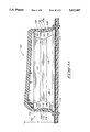
- FIG. 1 is an isometric view of a lap top computer having an alphanumeric keyboard with accompanying function keys of the preferred design.
- FIG. 2 is a fragmentary enlarged isolation view of a single keyswitch of the keyboard illustrated in FIG. 1, showing a keytop formed integrally with a common base sheet.
- FIG. 3 is a vertical cross sectional view taken along lines 3--3 in FIG. 1 showing the side profiles of three adjacent keyswitches in undepressed states.
- FIG. 4 is a side elevational view similar to FIG. 3 except showing one of the keyswitches being depressed.
- FIG. 5 is a vertical cross sectional view taken along line 5--5 in FIG. 2 showing the internal details of a single keyswitch structure.
- FIG. 6 is a vertical cross sectional view similar to FIG. 5 except showing the keyswitch in a depressed condition actuating electrical contacts.
- FIG. 7 is a horizontal cross sectional view taken along line 7--7 in FIG. 5.
- FIG. 8 is a horizontal cross sectional view taken along line 8--8 in FIG. 6.
- FIG. 9 is a vertical cross sectional view similar to FIG. 5 except showing an alternative keyswitch design.
- FIG. 10 is a graph showing the force versus travel of a keyswitch during both the downward motion and the upward motion in providing a substantially full-travel keyswitch with a tactile feel feature.
- FIG. 11 is a vertical cross sectional view similar to a view taken along line 5--5 in FIG. 2 showing another alternative keyswitch structure according to this invention.
- FIG. 11 illustrates the keyswitch in an expanded, non-actuating position.
- FIG. 12 is a vertical cross sectional view similar to FIG. 11 except showing the keyswitch in a depressed condition actuating an electrical contact.
- FIG. 13 is a vertical cross sectional view similar to that taken along line 5--5 in FIG. 2 and shows yet another alternative keyswitch structure according to this invention having a modified panel arrangement.
- FIG. 13 illustrates the keyswitch in an expanded, non-actuating position.
- FIG. 14 is a vertical cross sectional view similar to FIG. 13 except showing the keyswitch in an intermediate position.
- FIG. 15 is a vertical cross sectional view similar to FIG. 13 except showing the keyswitch in a depressed position actuating an electrical contact.
- FIG. 16 is a vertical cross sectional view of the FIG. 13 keyswitch, and illustrates a preferred embodiment of a force adjustment means for controllably varying the initial depression force required to depress the computer key.
- FIG. 17 is a vertical cross sectional view of a modified keyswitch structure similar to the FIG. 13 key design.
- FIG. 17 illustrates the keyswitch in an expanded, non-actuating position.
- FIG. 18 is a vertical cross sectional view similar to FIG. 17 except showing the modified keyswitch in a depressed condition actuating an electrical contact.
- FIG. 19 is an exploded, isometric view of a keyboard according to another embodiment of this invention.
- the FIG. 19 keyboard includes a keytop return sheet having multiple leaf springs interposed between the keytops and the switch membrane.
- FIG. 20 is a vertical cross sectional view showing a keyswitch structure of the FIG. 19 keyboard similar to the view taken along line 5--5 in FIG. 2.
- FIG. 20 illustrates the keyswitch in an expanded, non-actuating position.
- FIG. 21 is a vertical cross sectional view similar to FIG. 20 except showing the keyswitch in an intermediate position.
- FIG. 22 is a vertical cross sectional view similar to FIG. 20 except showing the keyswitch in a depressed position actuating an electrical contact.
- FIG. 1 A preferred embodiment of the improved keyboard is illustrated in FIG. 1 showing an alphanumeric keyboard designated generally with the numeral 10 that is an integral component of a lap top or notebook personal computer 12.
- the keyboard 10 includes a plurality of full-travel self leveling keyswitches 14.
- the keyswitches include alphanumeric keyswitches and function keyswitches.
- the keyswitches 14 have a low profile design that is principally illustrated in FIGS. 5 and 6. Low profile meaning that the distance "h" between the top of the key cap and the bottom of a support plate is approximately eight millimeters or less (FIGS. 5, 6, 11, and 12).
- each of the keyswitches has a full-travel feature meaning that the keytop travels a distance "t" of approximately four millimeters from its elevated non-actuating position to a depressed actuating position as illustrated in FIGS. 5, 6, 11, and 12.
- each keyswitch has a tactile feel (force-displacement characteristic) as illustrated in FIG. 10 in which the force required to initially depress the switch is greater than the force required to continue the downward movement through switch contact. Additionally, each of the keyswitches 14 have an overtravel feature in which the keyswitch may be further depressed after electrical contact has been made.
- the keyswitches 14 are arranged in the keyboard array or pattern at specific keyswitch locations dictated by the specific keyboard design and application. Although the alphanumeric keyboard 10 is illustrated in conjunction with a lap top or notebook personal computer, such alphanumeric keyboard 10 may be utilized in many other data entry environments.
- the keyboard 10 includes a keyboard housing 15 that houses the keyswitches 14.
- a rigid backing plate 16 is provided to support the keyswitches 14 as part of the keyboard 10 (FIGS. 3 and 6).
- the backing plate 16 may be made of a metal, or rigid plastic. In some embodiments, the rigid backing plate 16 may be an integral portion of the keyboard housing 15.
- the keyboard 10 includes a printed circuit board 18 as an integral part of the keyswitch for generating electrical signals through electrical contacts when the keyswitch is depressed.
- printed circuit board 18 is in the form of a flexible membrane structure having a membrane layer 20 with electrical contact elements 22 printed thereon at each keyswitch location.
- the printed circuit board 18 further includes a second membrane layer 24 having complementary electrical contacts 26 printed thereon.
- the membrane layers 20 and 24 are separated by spacer layer 28.
- spacer layer 28 has a section 30 between the keyswitch locations and a central section or island 32 at the keyswitch location itself.
- the electrical contact areas 22 and 26 are located between the spacer sections 30 and 32.
- the keyboard 10 further includes an integral key structure 40 overlying the printed circuit board 18 that is constructed from a moldable synthetic resin material; preferably of an elastomeric material such as polypropylene, or thermo-plastic elastomers.
- the integral key structure 40 includes a plurality of keytops 42 and keytop support substructures 44. Each of the keytops 42 has a top surface 42a and a lower surface 42b (FIGS. 5 and 6). The lower surface 42b defines a cavity 43 immediately below the keytop 42.
- the keytop support substructure 44 includes a base sheet 46 that overlies the printed circuit 18 having openings or apertures 47 at each keyswitch location.
- the individual key support means 48 prevents any noticeable lateral movement or wobble of the keytop 42 as it is depressed.
- the individual keytop support elements 48 include, in a preferred embodiment, at least three hinge members and preferably four hinge members 50a, 50b, 50c and 50d that are arranged in a substantially rectangular configuration with hinge elements 50a, 50c and 50b, 50d forming opposed hinge pairs.
- Each of the hinge members 50 includes a rigid upper hinge panel 52 that is integrally connected to the keytop 42 through an upper hinge web 54 defining an upper pivot axis 56.
- the rigid upper hinge panel 52 is designed to pivot about the upper pivot axis 56 from an expanded orientation (FIG. 5) to a contracted orientation (FIG. 6).
- the hinge member 50 further includes a rigid lower hinge panel 58 that is integrally interconnected to the base sheet 46 through a lower hinge web 60 defining a lower pivot axis 62.
- the lower hinge panel 58 is designed to pivot between an expanded orientation illustrated in FIG. 5 to a contracted orientation illustrated in FIG. 6 in which the lower hinge panel 58 projects into the aperture 47 as illustrated in FIG. 6.
- the upper hinge panel 52 and the lower hinge panel 58 are interconnected by an integral intermediate web 64 defining an intermediate pivot axis 66.
- the upper pivot axis 56 is positioned inward from the lower pivot axis 62 relative to the linear path of the keytop to cause the upper hinge panel 52 and the lower hinge panel 58 to pivot inward to a contracted and slightly downward orientation during overtravel.
- the panels of this embodiment are configured to fold inward beneath the keytop, the panels can be arranged to fold outward as the keytop is depressed. Examples of this alternative panel arrangement are described below with reference to FIGS. 13-22.
- the upper hinge panel 52 and the lower hinge panel 58 when in the expanded condition are substantially upright at a slight bend in which the combined bend angle ⁇ as illustrated in FIG. 5 is preferably between 170° and 178°.
- Such a feature causes the keyswitch to exhibit a tactile feel characteristic requiring a rather large force to initially depress the keyswitch and then a lesser force to continue the movement of the keytop during switch contact as illustrated in the force versus travel diagram of FIG. 10.
- the rigid upper hinge panel 52 includes an outer face surface 70 and an inner face surface 72.
- the distance between the surfaces 70 and 72 is preferably much greater than the corresponding thickness of the webs 54, 60 and 64 so that the thickness of the upper hinge panel provides considerably greater rigidity so that the upper hinge panel 52 will not buckle or appreciably bend as the keytop is depressed.
- the rigid upper hinge panel 52 extends between side surfaces 74 and 76 (FIG. 5). It should be noted that in the preferred embodiment the side surfaces 74 and 76 are inclined inward from the upper hinge web 54 to the intermediate hinge web 64.
- the rigid lower hinge panel 58 includes an outer face surface 78 and an inner face surface 80 defining a thickness that is considerably greater than the thickness of the webs 54, 60 and 64 so that the lower hinge panel does not buckle or appreciably bend but remains rigid relative to the webs as the keytop is depressed.
- the rigid lower hinge panel 58 includes side surfaces 82 and 84 that are inclined from the lower pivot axis 64 to the intermediate pivot axis 66 to form a "V" orientation, in conjunction with side surfaces 74 and 76, so that as the hinge members 50 fold inwardly they do not interfere with each other as illustrated in FIGS. 7 and 8.
- the distance between the side surfaces 74, 76 and 82, 84 is greater than 50% of the side dimension of the keytop 42 to maintain a rigid parallelogram configuration to maintain the keytop in a self-leveling orientation as it is depressed to prevent lateral movement of the keytop.
- the inward face surface 80 of the lower hinge element serves as an actuating member for engaging and deflecting the membrane layer 20 downward bringing electrical contact 22 into engagement with electrical contact 26 to generate an electrical signal indicating that the particular keyswitch has been depressed. It should be noted that overtravel is provided by further pivotal movement of the hinge panels 52 and 58 about the pivot axes 56 and 62.
- the integral key structure 40 further includes anchors 86 (FIGS. 5 and 6) that are formed integrally with the base sheet 46 for projecting downward through the membrane layers 20, 24, the spacer layer 28, and through the rigid backing plate 16 to anchor or secure the integral key structure 40 to the backing plate 16.
- anchors 86 FIGS. 5 and 6
- Alternative techniques may be utilized for anchoring the integral keyswitch structure 40 to the base plate 16.
- FIG. 10 illustrates the depression and release force-distance curves for the keyswitches as the keytops are depressed and released.
- the depression force-distance curve is depicted by the line 90.
- the release force-distance curve is depicted by the line 92. It should be noted that the force varies non-linearly with respect to distance to provide an initial large force for initial depression and a lower force when contact is made.
- the integral key structure 40 be formed of a moldable synthetic resin elastomeric material.
- the elastomeric material is of a rather uniform density in which the webs 54, 60 and 64 are defined by narrowed regions and the upper hinge panel 52 and the lower hinge panel 58 are defined by much thicker regions.
- the hinge panels 52 and 58 are rather rigid and the webs 54, 60 and 64 are rather flexible and resilient.
- the webs preferably have sufficient resiliency to cause the hinge members to move from the contracted orientations to their expanded orientations when the keyboard operator's finger is removed from the keytop 42.
- the elastomeric material may have a varied density to provide varied flexible resilient properties.
- the unitary keyswitch structure 40 may be formed of disparate synthetic resin materials to provide the necessary rigidity and resiliency of the hinge members.
- the integral key structure 40 is illustrated with the keytop 42, webs 54, 60, 64 and the base sheet 46 formed of one material that has elastomeric properties.
- the upper hinge panel 52 and the lower hinge panels 58 are formed of a disparate synthetic resin material in a two shot molding operation to provide the desired rigidity in the upper panel 52 and the lower panel 58.
- FIGS. 11 and 12 show another keyswitch structure 100 having modified keytop support elements 102 formed of two different types of materials.
- Support elements 102 preferably include four panel elements 104a, 104b, 104c, and 104d that are arranged in a substantially rectangular configuration (panel element 104d not being depicted in this view).
- Individual panel elements have an upper hinge panel 106, a lower hinge panel 108, and webs 110, 112, and 114. The operation of the panel elements are essentially the same as panel elements 50a-50d described above.
- Intermediate web 112 includes of a joint 116 which integrally interconnects the upper and lower panels 106, 108.
- Joint 116 is formed of the same material as found in the panels. A synthetic resin material is preferred.
- Intermediate web 112 also has a resilient material 118 provided at the joint to urge the hinged panels 106 and 108 toward their expanded orientation.
- resilient material 118 is stretched and yields under the force exerted by the keyboard operator.
- the resilient material 118 of web 112 elastically drives the panels back to the expanded orientation, thereby returning the keytop to the non-actuating, rest position (FIG. 11 ).
- resilient material 118 spans across joint 116 and is connected to, and lies partially on, interior surfaces 107 and 109 of respective upper panel 106 and lower panel 108.
- the interior surfaces 107 and 109 can be specially contoured, as shown, to accommodate the resilient material.
- the resilient material 118 can be formed of rubber, elastomers, or preferably, a composite of rubber and polypropylene. Such as composite is sold under the trademark Sanaprine.
- the alphanumeric keyboard 10 has many advantages including the ability to be manufactured at a relatively low cost while still providing for a low profile, full travel keyswitch structure that retains and provides for tactile feel and overtravel. It is further recognized that the individual keytop support elements 48, 102 not only maintain the keytop in a linear path without wobble or lateral movement, but additionally provides the actuation structure for actuating the electrical contacts without having to utilize other mechanisms.
- FIGS. 13-15 show a computer keyswitch structure 130 having a different panel construction and arrangement which can be incorporated into keyboard 10.
- Key 130 includes a keytop 132 and a keytop support element 134 which are preferably formed as an integral, unitary structure.
- Key 130 can be formed integrally with multiple other keys to form a unitary group of keys, similar to the structure discussed above with reference to FIG. 3, or can be constructed as a single key. It is preferred to have the flexibility to form the keys as groups, rows, or individually to satisfy various keyboard configurations. For example, the entire QWERTY key section may be formed of a single unitary structure, the function keys may be formed as a row of integrally connected keys, and the "escape" key may be formed as an individual component.
- Keytop support element 134 is designed to buckle as the a downward force is applied to the keytop 132. Keytop support element 134 guides the keytop along a linear path, without appreciable lateral wobble, from a rest, non-actuating position (FIG. 13) through an intermediate position (FIG. 14) to a depressed, actuating position (FIG. 15). Keytop support element 134 comprises multiple, and preferably, four hinge elements or panel assemblies 136a, 136b, 136c, 136d, of which only opposing paired hinge elements 136a and 136c are illustrated for purposes of clarity and explanation. Panel assemblies 136a and 136c interconnect base elements 138a and 138c with keytop 132. Keyswitch structure 130 is connected to base plate 16 via clips 139 which pass through apertures in plate 16 and printed circuit board 18.
- Individual hinge elements 136a and 136c include an upper hinge panel 140, a lower hinge panel 142, and an intermediate webbing 144.
- Upper panel 140 is hingedly coupled to keytop 132 via an upper web 145 for pivotal movement about an upper pivot axis 146 between a normally extended orientation when the keytop 132 is in the rest, non-actuating position of FIG. 13 and a contracted orientation when the keytop 132 is in the depressed actuating position of FIG. 15.
- Lower panel 142 is hingedly coupled to the base element via a lower web 147 to pivot about a lower pivot axis 148 in coordination with the pivotal movement of the upper hinge panel 140 between the normally expanded orientation and the contracted orientation.
- Intermediate web 144 interconnects the upper panel 140 and the lower panel 142 to permit pivotal movement about an intermediate axis 150 as the upper and lower panels move between the expanded and contracted orientations.
- Upper and lower panels 140, 142 are arranged in a diagonal pattern relative to keytop 132 and base 16.
- the panels are aligned along panel axes 152 (FIG. 13) between base elements 138a, 138c and keytop 132 which are transverse to the planes defined by the keytop 132 and the base 16.
- panel axes 152 are angled by angles ⁇ relative to a central axis 154, whereby central axis 154 also defines the linear path followed by the keytop 132 during its movement between the non-actuating and depressed actuating switch positions.
- each angle ⁇ is in a range of approximately 25-55 degrees.
- Keytop 132 has a top surface 132a and a lower surface 132b, and in combination with keytop support element 134, define an internal cavity 133 immediately below the keytop 132.
- keytop 132 has a deflectable plunger 135 for actuating the keyswitch.
- Plunger 135 is aligned above an electrical switch 158 of switch membrane 18, wherein the switch 158 has an upper electrical contact 22 and a lower electrical contact 26.
- the plunger and electrical switch are positioned centrally along axis 154, although other positions are possible.
- the panels of key 130 are arranged to fold outwardly, but in such a manner that does not interfere with neighboring keys.
- upper panel 140 pivots about axis 146 through an outward path away from central axis 154 (i.e., the left upper panel moves clockwise about axis 146 and the right upper panel moves counterclockwise about axis 146) and lower panel 142 pivots outwardly about axis 148 (i.e., the left lower panel moves counterclockwise about axis 148 and the right lower panel moves clockwise about axis 148).
- the longitudinal profile of the key remains within an acceptable area represented by boundary lines 156 (FIG. 14). Accordingly, even though the panels are configured to buckle outwardly, they do not enter the key space of neighboring keys and thus, do not disrupt or otherwise interfere with
- upper panel 140 continues to pivot outwardly about upper axis 146 (i.e., the left upper panel moves clockwise and the right upper panel moves counterclockwise).
- lower panel 140 stops moving in the outward direction and begins pivoting back inwardly about lower axis 148 (i.e., the left lower panel moves clockwise and the right lower panel moves counterclockwise).
- plunger 135 pushes upper electrical contact 22 into lower electrical contact 26 to actuate the keyswitch.
- Plunger 135 is preferably formed of a resilient material and deflects or otherwise deforms after engaging and actuating the electrical switch 158. The deformable plunger ensures good electrical contact between contacts 22 and 26 and creates a tactile overtravel feel to the keyboard operator.
- Plunger 135 can be configured to different lengths and deformable characteristics as desired to control the distance the key is depressed to actuate the switch and the amount of over travel following actuation.
- the panel assemblies 136 urge the keytop back to the rest position of FIG. 13 when the downward force thereto is removed.
- keytop support element 134 has a panel stop 160 for holding the upper and lower hinge panels 140, 142 in a selected arrangement when the panels are in their expanded orientations (FIG. 13).
- Panel stop 160 prevents the panel assemblies 136 from buckling inward beneath the keytop 132 as the keytop is depressed.
- Panel stop 160 can be shaped in a variety of ways.
- panel stop 160 is embodied as an angled projection or flange extending from lower panel 142 inwardly to cavity 133 and toward base 16.
- Panel stop 160 has a flat surface 162 which abuts against the switch membrane 18.
- the flange runs longitudinally across at least half of the lower panel.
- Alternative embodiments of the panel stop include one or more pegs or pins that project inwardly and downward from the lower panel.
- Individual panel stops 160 can be sized to create the desired initial force resistance to depression of the keytop. For example, if the panel stop is lengthened, the lower panel 142 is held in a more vertical orientation and the initial force resistance is less. Conversely, if the panel stop is shortened, the lower panel 142 is held in an angled orientation more and aligned with upper panel 140, thereby increasing the initial force resistance.
- FIG. 16 illustrates another feature of a keyboard constructed according to this invention which allows the user to adjust the initial force resistance of the computer keys.
- the keyboard includes a force adjustment means for controllably varying the selected panel arrangement to change the initial force resistance.
- force adjustment means is embodied as a subplate 164 movably mounted beneath base plate 16 to be vertically raised and lowered.
- Subplate 164 has plural members or platforms 166 which project upward through apertures 168 formed in base 16 and switch membrane 18. Apertures 168 are sized larger than platforms 166 to permit the platforms to easily pass therethrough.
- the platforms 166 engage the panel stops 160 at different elevations above base 16. This variation causes changes in the arrangement of the upper and lower hinge panels 140 and 142. As the platforms 166 are raised, the force resistance to depression of the keytop is decreased; conversely, as the platforms 166 are lowered, the initial force resistance is increased.
- Subplate 164 may be designed to be manually adjusted by the keyboard operator via a lift mechanism (not shown) accessible to the operator. Alternatively, subplate 164 may be designed to be adjusted to several elevations, but is fixed to a selected elevation during manufacturing and prior to shipping.
- key 130 (including keytop support structure 132 and keytop 134) is formed of a single material.
- the single material is preferably a unique composite consisting of a resilient substance, polypropylene, and a fibrous substance. This special composite achieves the desired stiffness in the panels and yet provides the required resilient flexing at the webbings.
- the resilient substance is preferably a rubber or elastomer, or most preferably, a composite of rubber and polypropylene, such as Sanaprine.
- the fibrous substance is preferably a carbon fiber or glass fiber.
- the Sanaprine rubber lends return memory force to cause the panel assemblies to spring back to their original rest state after the depression force is removed.
- Polypropylene affords durability, giving the key a long life cycle.
- the glass or carbon fibers add stiffness to the panel regions.
- the fibers run throughout the webbings and panels. Because the webbings have relatively small cross-sectional thicknesses in comparison to the thicker panels, fewer fiber strands traverse through the webbings. When the key is first depressed, these few fiber strands bend or break, thereby weakening the webbing areas and reducing the overall force used to depress the keytop. The fibers remain in tact, however, within the thick panels to strengthen and add rigidity to them.
- Example ratios of the elements contained in the composite are approximately 50% (by volume) of the resilient substance and approximately 50% (by volume) of a blend of the polypropylene and 40% milled fibers.
- FIGS. 17 and 18 illustrate a computer keyswitch 170 constructed similar to keyswitch 130 of FIGS. 13-16, but being formed of two materials.
- a first or resilient material 172 is used as the common thread to integrally interconnect the keytop 132 and keytop support means 134.
- Material 172 defines the intermediate webs between the upper and lower panels as well as the upper and lower webs which interconnect the panel assemblies to the key top and base elements.
- the first material 172 is preferably Sanaprine rubber.
- a second or rigid material 174 is then employed to form reinforced hinge panels 140, 142 and the keytop 132.
- the second material 174 is preferably a composite of polypropylene and fibers (such as carbon and glass fibers).
- Key 170 also has a different switch actuation construction. More particularly, keytop 132 has multiple pairs of deflectable plungers 176a/176b and 178a/178b projecting from its bottom surface. Electrical switches 180 of switch membrane 18 are aligned vertically beneath the paired plungers. When key 130 is depressed, plungers 176a/176b and 178a/178b engage and actuate electrical switches 180 and then bend and spread apart in opposing directions as shown to facilitate overtravel. Keytop 132 also has a limiting member 182 that "bottoms out" on the switch membrane 18 to halt downward travel of the keytop 132 after an adequate overtravel distance has been permitted by the deflecting plungers.
- FIG. 19 shows a computer keyboard 200 according to another preferred embodiment of this invention. Only twelve keyswitches are illustrated in this figure for discussion purposes.
- Keyboard 200 includes rigid backing plate 16, switch membrane 18 provided atop the backing plate, a keytop return sheet 202 atop switch membrane 18, multiple rows of individual keytop support means 204, and multiple keytops 206.
- keytops 206 are embodied as separate keycaps which are detachably connected to associated keytop support means 204.
- keytops 206 and keytop support means 204 can be integrally formed as a unitary molded key structure, such as that shown in FIG. 2.
- keytop return sheet 202 is interposed between switch membrane 18 and keytop support means 204.
- Keytop return sheet 202 defines a plurality of keytop return mechanisms 205 for associated keyswitches for imparting a spring force to bias respective keytops 20 from the depressed actuating position toward the non-actuating position.
- the individual keytop return mechanisms 205 are embodied as leaf springs 208 formed by being patterned in the single sheet, partially stamped or cut therefrom, and molded or bent to the desired spring-actuating shape.
- the keytop return sheet preferably comprises a material having resilient characteristics, such as a BeCu metal alloy.
- the single sheet design is advantageous in two respects. First, it is low cost because it consists only of a single sheet of material. Secondly, it is inexpensive and easy to manufacture because the leaf springs are simply stamped out of the single sheet. Less preferably, separate leaf springs, or other types of springs, can be attached to the keytop return sheet 202.
- FIGS. 20-22 illustrate a single keyswitch structure 210 of keyboard 200 of FIG. 19.
- keytop support means 204 is designed to buckle as a downward force is applied to the keycap 206.
- Keytop support element 204 guides the keycap along a linear path, without appreciable lateral wobble, from a rest, non-actuating position (FIG. 20) through an intermediate position (FIG. 21) to a depressed, actuating position (FIG. 22).
- Keytop support element 204 comprises the multiple, and preferably, four hinge elements or panel assemblies 136a, 136b, 136c, 136d, of which only opposing paired hinge elements 136a and 136c are illustrated for purposes of clarity and explanation. The construction and function of these panel assemblies are described above with respect to FIGS. 13-15.
- keytop support element 204 has a keycap subplatform 212 coupled to the upper panels 140 of hinge elements 136a-136d.
- Keycap subplatform 212 has a central, square-shaped recessed area or mortise 214.
- Keycap 206 has an upper surface 216 for receiving a finger of a keyboard user, and an underside square-shaped projection or tenon 218.
- the keycap projection 218 is complementary in size and shape for insertion into subplatform recessed area 214 to form a tenon and mortise joint for detachably connecting keytop 206 to keytop support element 204.
- Adhesives may also be applied in the tenon and mortise joint to help secure keytop 206 to keytop support element 204.
- Leaf spring 208 is aligned in the keyswitch structure to project upwardly from keytop return sheet 202 within the four panel elements of keytop support means 204 toward keytop 206.
- Leaf spring 208 has an upper end 220 which abuts against a bottom surface of keycap subplatform 212, a lower end 222 adjacent to sheet 202, and a curved, actuating, middle section 224 intermediate of the two ends.
- Leaf spring 208 is naturally sprung upwardly to force keycap 206 to the non-actuating rest position of FIG. 20. Upon application of a downward force, the leaf spring is pivoted about its lower end 222 as illustrated in FIGS. 21 and 22. Middle section 224 eventually engages upper membrane layer 20 and forces the layer and electrical contact 22 through the gap provided by spacer layer 28 until upper electrical contact 22 contacts lower electrical contact 26 on lower membrane layer 24 to generate an electric signal. In this manner, the middle section 224 of leaf spring 208 defines an actuating means for actuating the electric switch in membrane 18 as the keytop is depressed.
- leaf spring 208 continues to flatten or otherwise yield due to the bowing middle section 224 to permit overtravel of the keytop and thereby provide desired tactile feedback to the user.
- leaf spring 208 Upon release of the keyswitch, leaf spring 208 provides a return force to urge keytop 206 and keytop support means 204 back to their non-actuating, expanded positions. This biasing force can be combined with the inherent return force provided by the resilient webbing at the joint between the upper and lower panels in the panel elements to provide rapid keytop return.
Abstract
Description
Claims (25)
Priority Applications (5)
| Application Number | Priority Date | Filing Date | Title |
|---|---|---|---|
| US08/227,637 US5422447A (en) | 1992-09-01 | 1994-04-14 | Keyboard with full-travel, self-leveling keyswitches and return mechanism keyswitch |
| JP7527132A JPH08511910A (en) | 1994-04-14 | 1995-04-14 | Improved keyboard with fully mobile automatic leveling key switch and return mechanism key switch |
| PCT/US1995/004666 WO1995028727A1 (en) | 1994-04-14 | 1995-04-14 | Improved keyboard with full-travel, self-leveling keyswitches and return mechanism keyswitch |
| EP95917005A EP0708972A4 (en) | 1994-04-14 | 1995-04-14 | Improved keyboard with full-travel, self-leveling keyswitches and return mechanism keyswitch |
| AU23854/95A AU2385495A (en) | 1994-04-14 | 1995-04-14 | Improved keyboard with full-travel, self-leveling keyswitches and return mechanism keyswitch |
Applications Claiming Priority (3)
| Application Number | Priority Date | Filing Date | Title |
|---|---|---|---|
| US93910392A | 1992-09-01 | 1992-09-01 | |
| US08/093,042 US5358344A (en) | 1992-09-01 | 1993-07-15 | Keyboard with full-travel, self-leveling keyswitches |
| US08/227,637 US5422447A (en) | 1992-09-01 | 1994-04-14 | Keyboard with full-travel, self-leveling keyswitches and return mechanism keyswitch |
Related Parent Applications (1)
| Application Number | Title | Priority Date | Filing Date |
|---|---|---|---|
| US08/093,042 Continuation-In-Part US5358344A (en) | 1992-09-01 | 1993-07-15 | Keyboard with full-travel, self-leveling keyswitches |
Publications (1)
| Publication Number | Publication Date |
|---|---|
| US5422447A true US5422447A (en) | 1995-06-06 |
Family
ID=22853881
Family Applications (1)
| Application Number | Title | Priority Date | Filing Date |
|---|---|---|---|
| US08/227,637 Expired - Fee Related US5422447A (en) | 1992-09-01 | 1994-04-14 | Keyboard with full-travel, self-leveling keyswitches and return mechanism keyswitch |
Country Status (5)
| Country | Link |
|---|---|
| US (1) | US5422447A (en) |
| EP (1) | EP0708972A4 (en) |
| JP (1) | JPH08511910A (en) |
| AU (1) | AU2385495A (en) |
| WO (1) | WO1995028727A1 (en) |
Cited By (52)
| Publication number | Priority date | Publication date | Assignee | Title |
|---|---|---|---|---|
| US5541809A (en) * | 1993-09-20 | 1996-07-30 | Sony Corporation | Electronic equipments chassis made from bent sheet metal |
| US6031196A (en) * | 1998-11-12 | 2000-02-29 | Dresser Industries, Inc. | Push button switching system and method |
| US6056456A (en) * | 1997-12-12 | 2000-05-02 | Kinoshita; Ryohei | Keyboard device |
| US6174097B1 (en) | 1997-03-21 | 2001-01-16 | Simon Richard Daniel | Collapsible keyboard |
| WO2001023990A1 (en) * | 1999-09-28 | 2001-04-05 | Psion Digital Limited | Keyboard for an electronic device |
| US20010047927A1 (en) * | 2000-05-31 | 2001-12-06 | Kabushiki Kaisha Tokai Rika Denki Seisakusho | Switch button and method of manufacturing switch button |
| US6331850B1 (en) | 1997-11-12 | 2001-12-18 | Think Outside, Inc. | Collapsible keyboard |
| US20020013990A1 (en) * | 1999-07-27 | 2002-02-07 | Darfon Electronics Corp. | Elastic strip of keyboard and method for producing the same |
| US20020050934A1 (en) * | 1999-04-02 | 2002-05-02 | Robert Olodort | Foldable keyboard |
| US6390699B1 (en) | 1999-11-29 | 2002-05-21 | Associate Technology Limited | Keyboard with moveable base plate providing key travel |
| US6414253B1 (en) * | 1999-06-16 | 2002-07-02 | Samsung Electronics, Co., Ltd. | Object insertion/separation sensing apparatus |
| CN1106946C (en) * | 1997-05-09 | 2003-04-30 | 比尔·邦斯托弗 | Stress relieving keys |
| US20030173201A1 (en) * | 2002-03-15 | 2003-09-18 | Brother Kogyo Kabushiki Kaisha | Membrane switch, key switch using membrane switch, keyboard having key switches, and personal computer having keyboard |
| US20030209416A1 (en) * | 2002-05-10 | 2003-11-13 | Yao-Kun Tsai | Key cap with multiple-layer structure |
| US6781077B2 (en) | 2000-12-14 | 2004-08-24 | Think Outside, Inc. | Keyswitch and actuator structure |
| US20040194647A1 (en) * | 2001-08-30 | 2004-10-07 | Marko Areh | Electrical kitchen appliance |
| US6828516B1 (en) | 1996-10-08 | 2004-12-07 | Samsung Electronics, Co., Ltd. | Semi-elastic switch covering device for an electrical system having an external control panel and control apparatus for an electronic machine |
| US20070272533A1 (en) * | 2006-05-23 | 2007-11-29 | Darfon Electronics Corp. | Keyboard with wobble prevention structure |
| US20090024926A1 (en) * | 2007-07-17 | 2009-01-22 | Sony Corporation | Portable information terminal |
| US20090178911A1 (en) * | 2008-01-15 | 2009-07-16 | Chao Chen | Key dome assembly with improved tactile feedback |
| US20110220479A1 (en) * | 2010-03-15 | 2011-09-15 | Mi Zhou | Keys with double-diving-board spring mechanisms |
| US20120048700A1 (en) * | 2010-09-01 | 2012-03-01 | Sunrex Technology Corp. | Computer keys with inwardly tapered bottom |
| US8742275B1 (en) | 2011-12-16 | 2014-06-03 | Google Inc. | Cantilevered integrated function keys |
| US9449772B2 (en) | 2012-10-30 | 2016-09-20 | Apple Inc. | Low-travel key mechanisms using butterfly hinges |
| US9640347B2 (en) | 2013-09-30 | 2017-05-02 | Apple Inc. | Keycaps with reduced thickness |
| US9704665B2 (en) | 2014-05-19 | 2017-07-11 | Apple Inc. | Backlit keyboard including reflective component |
| US9704670B2 (en) | 2013-09-30 | 2017-07-11 | Apple Inc. | Keycaps having reduced thickness |
| US9710069B2 (en) | 2012-10-30 | 2017-07-18 | Apple Inc. | Flexible printed circuit having flex tails upon which keyboard keycaps are coupled |
| US9715978B2 (en) | 2014-05-27 | 2017-07-25 | Apple Inc. | Low travel switch assembly |
| US9779889B2 (en) | 2014-03-24 | 2017-10-03 | Apple Inc. | Scissor mechanism features for a keyboard |
| US9793066B1 (en) | 2014-01-31 | 2017-10-17 | Apple Inc. | Keyboard hinge mechanism |
| US9803310B1 (en) * | 2016-07-12 | 2017-10-31 | Haier Us Appliance Solutions, Inc. | Appliance interface and input chassis |
| US9870880B2 (en) | 2014-09-30 | 2018-01-16 | Apple Inc. | Dome switch and switch housing for keyboard assembly |
| US9908310B2 (en) | 2013-07-10 | 2018-03-06 | Apple Inc. | Electronic device with a reduced friction surface |
| US9916945B2 (en) | 2012-10-30 | 2018-03-13 | Apple Inc. | Low-travel key mechanisms using butterfly hinges |
| US9927895B2 (en) | 2013-02-06 | 2018-03-27 | Apple Inc. | Input/output device with a dynamically adjustable appearance and function |
| US9934915B2 (en) | 2015-06-10 | 2018-04-03 | Apple Inc. | Reduced layer keyboard stack-up |
| US9971084B2 (en) | 2015-09-28 | 2018-05-15 | Apple Inc. | Illumination structure for uniform illumination of keys |
| US9997304B2 (en) | 2015-05-13 | 2018-06-12 | Apple Inc. | Uniform illumination of keys |
| US9997308B2 (en) | 2015-05-13 | 2018-06-12 | Apple Inc. | Low-travel key mechanism for an input device |
| US10082880B1 (en) | 2014-08-28 | 2018-09-25 | Apple Inc. | System level features of a keyboard |
| US10083805B2 (en) | 2015-05-13 | 2018-09-25 | Apple Inc. | Keyboard for electronic device |
| US10115544B2 (en) | 2016-08-08 | 2018-10-30 | Apple Inc. | Singulated keyboard assemblies and methods for assembling a keyboard |
| US10128064B2 (en) | 2015-05-13 | 2018-11-13 | Apple Inc. | Keyboard assemblies having reduced thicknesses and method of forming keyboard assemblies |
| US10262814B2 (en) | 2013-05-27 | 2019-04-16 | Apple Inc. | Low travel switch assembly |
| TWI665701B (en) * | 2018-07-26 | 2019-07-11 | 達方電子股份有限公司 | Keyswitch |
| US10353485B1 (en) | 2016-07-27 | 2019-07-16 | Apple Inc. | Multifunction input device with an embedded capacitive sensing layer |
| US10466804B2 (en) * | 2017-01-12 | 2019-11-05 | Microsoft Technology Licensing, Llc | Composite unibody keyboard |
| US10755877B1 (en) | 2016-08-29 | 2020-08-25 | Apple Inc. | Keyboard for an electronic device |
| US10775850B2 (en) | 2017-07-26 | 2020-09-15 | Apple Inc. | Computer with keyboard |
| US10796863B2 (en) | 2014-08-15 | 2020-10-06 | Apple Inc. | Fabric keyboard |
| US11500538B2 (en) | 2016-09-13 | 2022-11-15 | Apple Inc. | Keyless keyboard with force sensing and haptic feedback |
Families Citing this family (4)
| Publication number | Priority date | Publication date | Assignee | Title |
|---|---|---|---|---|
| WO2000044014A1 (en) * | 1999-01-23 | 2000-07-27 | Levy David H | Keyboards with both individual and combination key output |
| TWI646567B (en) * | 2018-01-04 | 2019-01-01 | 達方電子股份有限公司 | Button structure |
| TWI645437B (en) * | 2018-02-12 | 2018-12-21 | 達方電子股份有限公司 | Key switch |
| TWI699805B (en) * | 2018-06-22 | 2020-07-21 | 達方電子股份有限公司 | Keyswitch structure |
Citations (23)
| Publication number | Priority date | Publication date | Assignee | Title |
|---|---|---|---|---|
| US3140365A (en) * | 1960-11-08 | 1964-07-07 | Mallory Timers Company | Plunger switch having integral plunger and spring |
| US3582594A (en) * | 1968-11-15 | 1971-06-01 | Mechanical Enterprises Inc | Actuator useable for electric switches and the like |
| US3668356A (en) * | 1971-01-04 | 1972-06-06 | Ibm | Mechanical key actuator including a cantilever beam restoring force means |
| US3829646A (en) * | 1972-03-04 | 1974-08-13 | Philips Corp | Push-button control member with push-through coupling |
| US3870840A (en) * | 1972-10-16 | 1975-03-11 | Sits Soc It Telecom Siemens | Switch pushbutton-type digit keyboard switch with leaf spring contract and actuator biasing means on common conductive frame |
| US3879025A (en) * | 1973-11-06 | 1975-04-22 | Us Army | Flat element spring |
| US3909564A (en) * | 1974-08-08 | 1975-09-30 | Amp Inc | Keyboard assembly with foldable printed circuit matrix switch array, and key actuator locking slide plate |
| US3982081A (en) * | 1974-09-04 | 1976-09-21 | Amp Incorporated | Keyboard assembly with overlapped flexible printed circuit cable switch |
| US3999025A (en) * | 1975-07-30 | 1976-12-21 | Burroughs Corporation | Low profile tactile feedback keyboard switch assembly |
| US4359612A (en) * | 1980-09-24 | 1982-11-16 | Engineering Research Applications, Inc. | Universal keyboard and method of producing same |
| US4376238A (en) * | 1980-03-12 | 1983-03-08 | International Computers Limited | Electrical devices |
| EP0094066A1 (en) * | 1982-05-07 | 1983-11-16 | Eberhard Burkart | Actuator for switching devices |
| US4490587A (en) * | 1983-04-07 | 1984-12-25 | Microdot Inc. | Switch assembly |
| US4491702A (en) * | 1982-02-01 | 1985-01-01 | Sun Arrow Koeki Company Ltd. | Key-top panel and keyboard structure using the panel |
| US4540865A (en) * | 1983-03-01 | 1985-09-10 | Plessey Overseas Limited | Push buttons |
| US4588093A (en) * | 1982-12-20 | 1986-05-13 | Field Frank P | Merchandise display device |
| US4604509A (en) * | 1985-02-01 | 1986-08-05 | Honeywell Inc. | Elastomeric push button return element for providing enhanced tactile feedback |
| USRE32419E (en) * | 1981-03-16 | 1987-05-12 | Engineering Research Applications, Inc. | Molded keyboard and method of fabricating same |
| US4668843A (en) * | 1985-02-12 | 1987-05-26 | Nippon Gakki Seizo Kabushiki Kaisha | Keyboard switch apparatus for electronic musical instrument |
| EP0241667A2 (en) * | 1986-03-05 | 1987-10-21 | Chisso Corporation | Acoustic vibration sheet and polypropylene composition for the same |
| US4764770A (en) * | 1986-06-11 | 1988-08-16 | Hewlett-Packard Company | Stabilized molded rubber keyboards |
| US4839474A (en) * | 1984-02-03 | 1989-06-13 | Key Innovations Limited | Switches and keyboards |
| US5358344A (en) * | 1992-09-01 | 1994-10-25 | Key Tronic Corporation | Keyboard with full-travel, self-leveling keyswitches |
Family Cites Families (2)
| Publication number | Priority date | Publication date | Assignee | Title |
|---|---|---|---|---|
| GB2141874B (en) * | 1983-03-31 | 1987-04-01 | Cherry Electrical Prod | Keyboard with membrane switch array |
| US5360955A (en) * | 1992-08-18 | 1994-11-01 | Key Tronic Corporation | Computer keyboard with cantilever switch design and improved PCB/switch membrane interface |
-
1994
- 1994-04-14 US US08/227,637 patent/US5422447A/en not_active Expired - Fee Related
-
1995
- 1995-04-14 WO PCT/US1995/004666 patent/WO1995028727A1/en not_active Application Discontinuation
- 1995-04-14 EP EP95917005A patent/EP0708972A4/en not_active Withdrawn
- 1995-04-14 JP JP7527132A patent/JPH08511910A/en active Pending
- 1995-04-14 AU AU23854/95A patent/AU2385495A/en not_active Abandoned
Patent Citations (23)
| Publication number | Priority date | Publication date | Assignee | Title |
|---|---|---|---|---|
| US3140365A (en) * | 1960-11-08 | 1964-07-07 | Mallory Timers Company | Plunger switch having integral plunger and spring |
| US3582594A (en) * | 1968-11-15 | 1971-06-01 | Mechanical Enterprises Inc | Actuator useable for electric switches and the like |
| US3668356A (en) * | 1971-01-04 | 1972-06-06 | Ibm | Mechanical key actuator including a cantilever beam restoring force means |
| US3829646A (en) * | 1972-03-04 | 1974-08-13 | Philips Corp | Push-button control member with push-through coupling |
| US3870840A (en) * | 1972-10-16 | 1975-03-11 | Sits Soc It Telecom Siemens | Switch pushbutton-type digit keyboard switch with leaf spring contract and actuator biasing means on common conductive frame |
| US3879025A (en) * | 1973-11-06 | 1975-04-22 | Us Army | Flat element spring |
| US3909564A (en) * | 1974-08-08 | 1975-09-30 | Amp Inc | Keyboard assembly with foldable printed circuit matrix switch array, and key actuator locking slide plate |
| US3982081A (en) * | 1974-09-04 | 1976-09-21 | Amp Incorporated | Keyboard assembly with overlapped flexible printed circuit cable switch |
| US3999025A (en) * | 1975-07-30 | 1976-12-21 | Burroughs Corporation | Low profile tactile feedback keyboard switch assembly |
| US4376238A (en) * | 1980-03-12 | 1983-03-08 | International Computers Limited | Electrical devices |
| US4359612A (en) * | 1980-09-24 | 1982-11-16 | Engineering Research Applications, Inc. | Universal keyboard and method of producing same |
| USRE32419E (en) * | 1981-03-16 | 1987-05-12 | Engineering Research Applications, Inc. | Molded keyboard and method of fabricating same |
| US4491702A (en) * | 1982-02-01 | 1985-01-01 | Sun Arrow Koeki Company Ltd. | Key-top panel and keyboard structure using the panel |
| EP0094066A1 (en) * | 1982-05-07 | 1983-11-16 | Eberhard Burkart | Actuator for switching devices |
| US4588093A (en) * | 1982-12-20 | 1986-05-13 | Field Frank P | Merchandise display device |
| US4540865A (en) * | 1983-03-01 | 1985-09-10 | Plessey Overseas Limited | Push buttons |
| US4490587A (en) * | 1983-04-07 | 1984-12-25 | Microdot Inc. | Switch assembly |
| US4839474A (en) * | 1984-02-03 | 1989-06-13 | Key Innovations Limited | Switches and keyboards |
| US4604509A (en) * | 1985-02-01 | 1986-08-05 | Honeywell Inc. | Elastomeric push button return element for providing enhanced tactile feedback |
| US4668843A (en) * | 1985-02-12 | 1987-05-26 | Nippon Gakki Seizo Kabushiki Kaisha | Keyboard switch apparatus for electronic musical instrument |
| EP0241667A2 (en) * | 1986-03-05 | 1987-10-21 | Chisso Corporation | Acoustic vibration sheet and polypropylene composition for the same |
| US4764770A (en) * | 1986-06-11 | 1988-08-16 | Hewlett-Packard Company | Stabilized molded rubber keyboards |
| US5358344A (en) * | 1992-09-01 | 1994-10-25 | Key Tronic Corporation | Keyboard with full-travel, self-leveling keyswitches |
Cited By (92)
| Publication number | Priority date | Publication date | Assignee | Title |
|---|---|---|---|---|
| US5541809A (en) * | 1993-09-20 | 1996-07-30 | Sony Corporation | Electronic equipments chassis made from bent sheet metal |
| US6828516B1 (en) | 1996-10-08 | 2004-12-07 | Samsung Electronics, Co., Ltd. | Semi-elastic switch covering device for an electrical system having an external control panel and control apparatus for an electronic machine |
| US6174097B1 (en) | 1997-03-21 | 2001-01-16 | Simon Richard Daniel | Collapsible keyboard |
| CN1106946C (en) * | 1997-05-09 | 2003-04-30 | 比尔·邦斯托弗 | Stress relieving keys |
| US6563434B1 (en) | 1997-11-12 | 2003-05-13 | Think Outside, Inc. | System and method for detecting key actuation in a keyboard |
| US20030122691A1 (en) * | 1997-11-12 | 2003-07-03 | Robert Olodort | System and method for detecting key actuation in a keyboard |
| US6331850B1 (en) | 1997-11-12 | 2001-12-18 | Think Outside, Inc. | Collapsible keyboard |
| US7084787B2 (en) | 1997-11-12 | 2006-08-01 | Think Outside, Inc. | System and method for detecting key actuation in a keyboard |
| US20060284742A1 (en) * | 1997-11-12 | 2006-12-21 | Robert Olodort | System and method for detecting key actuation in a keyboard |
| US7782230B2 (en) | 1997-11-12 | 2010-08-24 | Robert Olodort | Detecting key actuation in a keyboard |
| US8031087B2 (en) | 1997-11-12 | 2011-10-04 | Wakisoni Investments Pa, L.L.C. | Detecting key actuation in a keyboard |
| US6056456A (en) * | 1997-12-12 | 2000-05-02 | Kinoshita; Ryohei | Keyboard device |
| US6031196A (en) * | 1998-11-12 | 2000-02-29 | Dresser Industries, Inc. | Push button switching system and method |
| US6734809B1 (en) | 1999-04-02 | 2004-05-11 | Think Outside, Inc. | Foldable keyboard |
| US6839002B2 (en) | 1999-04-02 | 2005-01-04 | Think Outside, Inc. | Foldable keyboard |
| US20020050934A1 (en) * | 1999-04-02 | 2002-05-02 | Robert Olodort | Foldable keyboard |
| US20040169642A1 (en) * | 1999-04-02 | 2004-09-02 | Robert Olodort | Foldable keyboard |
| US20040169593A1 (en) * | 1999-04-02 | 2004-09-02 | Robert Olodort | Foldable keyboard |
| US6972699B2 (en) | 1999-04-02 | 2005-12-06 | Think Outside, Inc. | Foldable keyboard |
| US6894626B2 (en) | 1999-04-02 | 2005-05-17 | Think Outside, Inc. | Foldable keyboard |
| US6414253B1 (en) * | 1999-06-16 | 2002-07-02 | Samsung Electronics, Co., Ltd. | Object insertion/separation sensing apparatus |
| US20020013990A1 (en) * | 1999-07-27 | 2002-02-07 | Darfon Electronics Corp. | Elastic strip of keyboard and method for producing the same |
| WO2001023990A1 (en) * | 1999-09-28 | 2001-04-05 | Psion Digital Limited | Keyboard for an electronic device |
| US6390699B1 (en) | 1999-11-29 | 2002-05-21 | Associate Technology Limited | Keyboard with moveable base plate providing key travel |
| US6633011B2 (en) * | 2000-05-31 | 2003-10-14 | Kabushiki Kaisha Tokai Rika Denki Seisakusho | Switch button and method of manufacturing switch button |
| US20010047927A1 (en) * | 2000-05-31 | 2001-12-06 | Kabushiki Kaisha Tokai Rika Denki Seisakusho | Switch button and method of manufacturing switch button |
| US6781077B2 (en) | 2000-12-14 | 2004-08-24 | Think Outside, Inc. | Keyswitch and actuator structure |
| US7193171B2 (en) * | 2001-08-30 | 2007-03-20 | Bsh Bosch Und Siemens Hausgeraete Gmbh | Electrical kitchen appliance |
| US20040194647A1 (en) * | 2001-08-30 | 2004-10-07 | Marko Areh | Electrical kitchen appliance |
| US20030173201A1 (en) * | 2002-03-15 | 2003-09-18 | Brother Kogyo Kabushiki Kaisha | Membrane switch, key switch using membrane switch, keyboard having key switches, and personal computer having keyboard |
| US6797906B2 (en) * | 2002-03-15 | 2004-09-28 | Brother Kogyo Kabushiki Kaisha | Membrane switch, key switch using membrane switch, keyboard having key switches, and personal computer having keyboard |
| US20030209416A1 (en) * | 2002-05-10 | 2003-11-13 | Yao-Kun Tsai | Key cap with multiple-layer structure |
| US20070272533A1 (en) * | 2006-05-23 | 2007-11-29 | Darfon Electronics Corp. | Keyboard with wobble prevention structure |
| US7728243B2 (en) * | 2006-05-23 | 2010-06-01 | Darfon Electronics Corp. | Keyboard with wobble prevention structure |
| US20090024926A1 (en) * | 2007-07-17 | 2009-01-22 | Sony Corporation | Portable information terminal |
| US20090178911A1 (en) * | 2008-01-15 | 2009-07-16 | Chao Chen | Key dome assembly with improved tactile feedback |
| US7700890B2 (en) | 2008-01-15 | 2010-04-20 | Research In Motion Limited | Key dome assembly with improved tactile feedback |
| US8809703B2 (en) | 2010-03-15 | 2014-08-19 | Apple Inc. | Keys with double-diving-board spring mechanisms |
| US8212162B2 (en) | 2010-03-15 | 2012-07-03 | Apple Inc. | Keys with double-diving-board spring mechanisms |
| US8362373B2 (en) | 2010-03-15 | 2013-01-29 | Apple Inc. | Keys with double-diving-board spring mechanisms |
| US20110220479A1 (en) * | 2010-03-15 | 2011-09-15 | Mi Zhou | Keys with double-diving-board spring mechanisms |
| US20120048700A1 (en) * | 2010-09-01 | 2012-03-01 | Sunrex Technology Corp. | Computer keys with inwardly tapered bottom |
| US8742275B1 (en) | 2011-12-16 | 2014-06-03 | Google Inc. | Cantilevered integrated function keys |
| US10211008B2 (en) | 2012-10-30 | 2019-02-19 | Apple Inc. | Low-travel key mechanisms using butterfly hinges |
| US11023081B2 (en) | 2012-10-30 | 2021-06-01 | Apple Inc. | Multi-functional keyboard assemblies |
| US10699856B2 (en) | 2012-10-30 | 2020-06-30 | Apple Inc. | Low-travel key mechanisms using butterfly hinges |
| US9710069B2 (en) | 2012-10-30 | 2017-07-18 | Apple Inc. | Flexible printed circuit having flex tails upon which keyboard keycaps are coupled |
| US9761389B2 (en) | 2012-10-30 | 2017-09-12 | Apple Inc. | Low-travel key mechanisms with butterfly hinges |
| US10254851B2 (en) | 2012-10-30 | 2019-04-09 | Apple Inc. | Keyboard key employing a capacitive sensor and dome |
| US9449772B2 (en) | 2012-10-30 | 2016-09-20 | Apple Inc. | Low-travel key mechanisms using butterfly hinges |
| US9916945B2 (en) | 2012-10-30 | 2018-03-13 | Apple Inc. | Low-travel key mechanisms using butterfly hinges |
| US9927895B2 (en) | 2013-02-06 | 2018-03-27 | Apple Inc. | Input/output device with a dynamically adjustable appearance and function |
| US10114489B2 (en) | 2013-02-06 | 2018-10-30 | Apple Inc. | Input/output device with a dynamically adjustable appearance and function |
| US10262814B2 (en) | 2013-05-27 | 2019-04-16 | Apple Inc. | Low travel switch assembly |
| US10556408B2 (en) | 2013-07-10 | 2020-02-11 | Apple Inc. | Electronic device with a reduced friction surface |
| US9908310B2 (en) | 2013-07-10 | 2018-03-06 | Apple Inc. | Electronic device with a reduced friction surface |
| US9704670B2 (en) | 2013-09-30 | 2017-07-11 | Apple Inc. | Keycaps having reduced thickness |
| US10224157B2 (en) | 2013-09-30 | 2019-03-05 | Apple Inc. | Keycaps having reduced thickness |
| US11699558B2 (en) | 2013-09-30 | 2023-07-11 | Apple Inc. | Keycaps having reduced thickness |
| US9640347B2 (en) | 2013-09-30 | 2017-05-02 | Apple Inc. | Keycaps with reduced thickness |
| US10804051B2 (en) | 2013-09-30 | 2020-10-13 | Apple Inc. | Keycaps having reduced thickness |
| US10002727B2 (en) | 2013-09-30 | 2018-06-19 | Apple Inc. | Keycaps with reduced thickness |
| US9793066B1 (en) | 2014-01-31 | 2017-10-17 | Apple Inc. | Keyboard hinge mechanism |
| US9779889B2 (en) | 2014-03-24 | 2017-10-03 | Apple Inc. | Scissor mechanism features for a keyboard |
| US9704665B2 (en) | 2014-05-19 | 2017-07-11 | Apple Inc. | Backlit keyboard including reflective component |
| US9715978B2 (en) | 2014-05-27 | 2017-07-25 | Apple Inc. | Low travel switch assembly |
| US10796863B2 (en) | 2014-08-15 | 2020-10-06 | Apple Inc. | Fabric keyboard |
| US10082880B1 (en) | 2014-08-28 | 2018-09-25 | Apple Inc. | System level features of a keyboard |
| US10128061B2 (en) | 2014-09-30 | 2018-11-13 | Apple Inc. | Key and switch housing for keyboard assembly |
| US10879019B2 (en) | 2014-09-30 | 2020-12-29 | Apple Inc. | Light-emitting assembly for keyboard |
| US10134539B2 (en) | 2014-09-30 | 2018-11-20 | Apple Inc. | Venting system and shield for keyboard |
| US10192696B2 (en) | 2014-09-30 | 2019-01-29 | Apple Inc. | Light-emitting assembly for keyboard |
| US9870880B2 (en) | 2014-09-30 | 2018-01-16 | Apple Inc. | Dome switch and switch housing for keyboard assembly |
| US10424446B2 (en) | 2015-05-13 | 2019-09-24 | Apple Inc. | Keyboard assemblies having reduced thickness and method of forming keyboard assemblies |
| US9997308B2 (en) | 2015-05-13 | 2018-06-12 | Apple Inc. | Low-travel key mechanism for an input device |
| US9997304B2 (en) | 2015-05-13 | 2018-06-12 | Apple Inc. | Uniform illumination of keys |
| US10128064B2 (en) | 2015-05-13 | 2018-11-13 | Apple Inc. | Keyboard assemblies having reduced thicknesses and method of forming keyboard assemblies |
| US10083805B2 (en) | 2015-05-13 | 2018-09-25 | Apple Inc. | Keyboard for electronic device |
| US10083806B2 (en) | 2015-05-13 | 2018-09-25 | Apple Inc. | Keyboard for electronic device |
| US10468211B2 (en) | 2015-05-13 | 2019-11-05 | Apple Inc. | Illuminated low-travel key mechanism for a keyboard |
| US9934915B2 (en) | 2015-06-10 | 2018-04-03 | Apple Inc. | Reduced layer keyboard stack-up |
| US10310167B2 (en) | 2015-09-28 | 2019-06-04 | Apple Inc. | Illumination structure for uniform illumination of keys |
| US9971084B2 (en) | 2015-09-28 | 2018-05-15 | Apple Inc. | Illumination structure for uniform illumination of keys |
| US9803310B1 (en) * | 2016-07-12 | 2017-10-31 | Haier Us Appliance Solutions, Inc. | Appliance interface and input chassis |
| US10353485B1 (en) | 2016-07-27 | 2019-07-16 | Apple Inc. | Multifunction input device with an embedded capacitive sensing layer |
| US10115544B2 (en) | 2016-08-08 | 2018-10-30 | Apple Inc. | Singulated keyboard assemblies and methods for assembling a keyboard |
| US11282659B2 (en) | 2016-08-08 | 2022-03-22 | Apple Inc. | Singulated keyboard assemblies and methods for assembling a keyboard |
| US10755877B1 (en) | 2016-08-29 | 2020-08-25 | Apple Inc. | Keyboard for an electronic device |
| US11500538B2 (en) | 2016-09-13 | 2022-11-15 | Apple Inc. | Keyless keyboard with force sensing and haptic feedback |
| US10466804B2 (en) * | 2017-01-12 | 2019-11-05 | Microsoft Technology Licensing, Llc | Composite unibody keyboard |
| US10775850B2 (en) | 2017-07-26 | 2020-09-15 | Apple Inc. | Computer with keyboard |
| TWI665701B (en) * | 2018-07-26 | 2019-07-11 | 達方電子股份有限公司 | Keyswitch |
Also Published As
| Publication number | Publication date |
|---|---|
| AU2385495A (en) | 1995-11-10 |
| EP0708972A1 (en) | 1996-05-01 |
| EP0708972A4 (en) | 1997-12-17 |
| WO1995028727A1 (en) | 1995-10-26 |
| JPH08511910A (en) | 1996-12-10 |
Similar Documents
| Publication | Publication Date | Title |
|---|---|---|
| US5422447A (en) | Keyboard with full-travel, self-leveling keyswitches and return mechanism keyswitch | |
| US5358344A (en) | Keyboard with full-travel, self-leveling keyswitches | |
| EP0543649B1 (en) | Keyswitch assembly | |
| JP2577359Y2 (en) | Key switch device | |
| US5499041A (en) | Keyboard integrated pointing device | |
| US4677268A (en) | Elastomeric switch control device | |
| EP3005392B1 (en) | Low travel switch assembly | |
| US4362911A (en) | Membrane keyboard switch assembly having selectable tactile properties | |
| KR100194829B1 (en) | Pushbutton switch | |
| US5278371A (en) | Keyswitch assembly with support mechanism coupled to support plate beneath printed circuit board | |
| US4440515A (en) | Keybar keyboard | |
| JPH0425652B2 (en) | ||
| US5562203A (en) | Keyswitch | |
| US6224279B1 (en) | Keyboard having integrally molded keyswitch base | |
| US6555774B1 (en) | Lever keyswitch | |
| CN110071004B (en) | Keyboard device | |
| CN112466693A (en) | Keyboard device and key structure thereof | |
| JPH11345535A (en) | Key switch | |
| JP2602421Y2 (en) | Key switch | |
| CA2186789C (en) | Ergonomic computer keyboard (and key) | |
| JP3045296B2 (en) | Key switch | |
| JP3318320B2 (en) | Key switch device | |
| JP2607630Y2 (en) | Key switch | |
| JP3392841B2 (en) | Key switch device | |
| JPH03208217A (en) | Push-button switch |
Legal Events
| Date | Code | Title | Description |
|---|---|---|---|
| AS | Assignment |
Owner name: MICRON SEMICONDUCTOR, INC., IDAHO Free format text: ASSIGNMENT OF ASSIGNORS INTEREST;ASSIGNOR:SPENCE, KENNY RAY;REEL/FRAME:006966/0796 Effective date: 19940412 |
|
| AS | Assignment |
Owner name: KEY TRONIC CORPORATION, WASHINGTON Free format text: SECURITY AGREEMENT TERMINATION;ASSIGNOR:CIT GROUP/BUSINESS CREDIT, INC.;REEL/FRAME:008290/0482 Effective date: 19961231 Owner name: GENERAL ELECTRIC CAPITAL CORPORATION, ILLINOIS Free format text: SECURITY AGREEMENT;ASSIGNOR:KEY TRONIC CORPORATION;REEL/FRAME:008283/0722 Effective date: 19961231 |
|
| REMI | Maintenance fee reminder mailed | ||
| LAPS | Lapse for failure to pay maintenance fees | ||
| FP | Lapsed due to failure to pay maintenance fee |
Effective date: 19990606 |
|
| AS | Assignment |
Owner name: GENERAL ELECTRIC CAPITAL CORPORATION, ILLINOIS Free format text: SECURITY AGREEMENT;ASSIGNOR:KEY TRONIC CORPORATION;REEL/FRAME:011923/0323 Effective date: 19961231 |
|
| AS | Assignment |
Owner name: KEY TRONIC CORPORATION, WASHINGTON Free format text: RELEASE;ASSIGNOR:GENERAL ELECTRIC CAPITAL CORPORATION;REEL/FRAME:012302/0259 Effective date: 20010928 |
|
| AS | Assignment |
Owner name: THE CIT GROUP/BUSINESS CREDIT, INC., CALIFORNIA Free format text: SECURITY INTEREST;ASSIGNOR:KEY TRONIC CORPORATION;REEL/FRAME:012302/0381 Effective date: 20010822 |
|
| STCH | Information on status: patent discontinuation |
Free format text: PATENT EXPIRED DUE TO NONPAYMENT OF MAINTENANCE FEES UNDER 37 CFR 1.362 |