US5425216A - Method of making reclosable plastic bags on a form, fill and seal machine with open zipper profiles - Google Patents
Method of making reclosable plastic bags on a form, fill and seal machine with open zipper profiles Download PDFInfo
- Publication number
- US5425216A US5425216A US08/254,239 US25423994A US5425216A US 5425216 A US5425216 A US 5425216A US 25423994 A US25423994 A US 25423994A US 5425216 A US5425216 A US 5425216A
- Authority
- US
- United States
- Prior art keywords
- interlocking members
- filling tube
- tube
- thermoplastic film
- interlocking
- Prior art date
- Legal status (The legal status is an assumption and is not a legal conclusion. Google has not performed a legal analysis and makes no representation as to the accuracy of the status listed.)
- Expired - Fee Related
Links
Images


Classifications
-
- B—PERFORMING OPERATIONS; TRANSPORTING
- B65—CONVEYING; PACKING; STORING; HANDLING THIN OR FILAMENTARY MATERIAL
- B65B—MACHINES, APPARATUS OR DEVICES FOR, OR METHODS OF, PACKAGING ARTICLES OR MATERIALS; UNPACKING
- B65B61/00—Auxiliary devices, not otherwise provided for, for operating on sheets, blanks, webs, binding material, containers or packages
- B65B61/18—Auxiliary devices, not otherwise provided for, for operating on sheets, blanks, webs, binding material, containers or packages for making package-opening or unpacking elements
- B65B61/188—Auxiliary devices, not otherwise provided for, for operating on sheets, blanks, webs, binding material, containers or packages for making package-opening or unpacking elements by applying or incorporating profile-strips, e.g. for reclosable bags
-
- B—PERFORMING OPERATIONS; TRANSPORTING
- B65—CONVEYING; PACKING; STORING; HANDLING THIN OR FILAMENTARY MATERIAL
- B65B—MACHINES, APPARATUS OR DEVICES FOR, OR METHODS OF, PACKAGING ARTICLES OR MATERIALS; UNPACKING
- B65B9/00—Enclosing successive articles, or quantities of material, e.g. liquids or semiliquids, in flat, folded, or tubular webs of flexible sheet material; Subdividing filled flexible tubes to form packages
- B65B9/10—Enclosing successive articles, or quantities of material, in preformed tubular webs, or in webs formed into tubes around filling nozzles, e.g. extruded tubular webs
- B65B9/20—Enclosing successive articles, or quantities of material, in preformed tubular webs, or in webs formed into tubes around filling nozzles, e.g. extruded tubular webs the webs being formed into tubes in situ around the filling nozzles
- B65B9/213—Enclosing successive articles, or quantities of material, in preformed tubular webs, or in webs formed into tubes around filling nozzles, e.g. extruded tubular webs the webs being formed into tubes in situ around the filling nozzles the web having intermittent motion
Definitions
- the present invention relates to improvements in the manufacturing of reclosable plastic bags, and, more particularly, to a method which permits such bags to be formed as they are fed over a filling spout of a filling machine whereby the bags are formed and simultaneously filled with a product.
- U.S. Pat. No. 4,709,533 shows an apparatus and a method wherein film is fed downwardly wrapped around a form-fill tube and the edges of the film are brought together pressed between pressing rollers guiding the edges together so that an outer seal can be formed.
- Means are provided for feeding interlocked zipper members between the film layers and between the rollers and the filling spout. Following the rollers, there are located uniquely positioned and shaped bars which include inner bars that have a space between them to guide the center portion of the zipper and these bars also form a backing for outer heated bars which seal the webs of the zipper to the inner surface of the bag film.
- the outer bars also extend around the edges of the bag to simultaneously form an outer security seal or lip seal.
- the thus formed and sealed zipper tube is filled through the spout and cross-seals with cross-cutters to complete the individual bags.
- U.S. Pat. No. 4,894,975 also shows an apparatus and method wherein film is fed downwardly wrapped around a form-fill tube and the edges of the film are brought together in adjacency.
- the adjacent edges of the film are joined such as by heat sealing to interlocked zipper members, which thereafter form the sole juncture between the edges of the film and which zipper members provide a reclosable opening for the top of the completed bag.
- a web extends between the zipper strips, either above or below the interlocking elements, which web can be constructed of a weight and width with optimum characteristics for forming a security seal at the top of the bag and forming a tamper-evident seal.
- a bag is formed wherein the film of the bag has optimum characteristics for the bag, and the plastic of the zipper and of the web therebetween have optimum characteristics for the functions of the zipper and functions of the security tamper-evident seal.
- the thus formed and sealed zipper tube is filled through the spout and cross-sealed with cross-cutters to complete the individual bags.
- U.S. Pat. No. 5,046,300 shows a method and apparatus for forming reclosable packages wherein a flat packaging film is formed over a forming shoulder and into a tubular shape about a central member.
- the packaging film is advanced vertically downward along the length of the central member, and a reclosable profile element is threaded inside the tubular shape of the packaging film.
- the tubular packaging film is deformed to form a longitudinally extending loop of packaging film, and the interlocked zipper members are guided into the loop.
- the interlocked zipper members are then adhered to the inner surface of the loop of packaging film.
- the thus formed and sealed zipper tube is filled through the spout and cross-sealed with cross-cutters to complete the individual bags.
- a thermoplastic film is wrapped around the filling spout enclosing the zipper strip, and the lateral edges of the film are bonded together to form a longitudinal seam.
- the zipper strip webs are attached by sealing bars to the inside of the tube so formed from the thermoplastic film between the fill tube and the sealing bars.
- transverse seams are formed to produce individual reclosable packages, which may also be separated from one another.
- the packages are filled with product during the course of their manufacture.
- the zipper strip is always delivered to the fill tube in interlocked condition.
- the present invention represents an alternate approach toward the attachment of reclosable profile elements to a tubular packaging film, and toward the formation of reclosable plastic bags containing a product, wherein the profile elements are enclosed within a tube of thermoplastic film and attached to the inner surface thereof on the fill tube of a form-fill-and-seal machine in an uninterlocked condition.
- This method provides a number of advantages. It minimizes the likelihood of the formation of wrinkles in the film in the cross seal area and allows different zipper constructions to be relatively easily interchanged in the form-fill-and-seal machine.
- the present invention is a method for forming reclosable packages from a sheet of thermoplastic film on a form-fill-and-seal (FFS) machine, wherein a continuous supply of zipper strip having first and second interlocking members is fed toward and guided longitudinally parallel to the filling tube thereof in an uninterlocked condition.
- FFS form-fill-and-seal
- thermoplastic film is also fed toward the filling tube, and is wrapped therearound enclosing the first and second interlocking members within the tube so formed.
- the lateral edges of the thermoplastic film are sealed together with a longitudinal seam to close the tube at a point away from the zipper location.
- At least one of the first and second interlocking members is attached to the inside of the tube of thermoplastic film by sealing, bonding or welding, and a fold is formed in said tube to bring the first and second interlocking members into a facing relationship.
- the interlocking members are then interlocked with one another.
- transverse seams are formed to produce individual reclosable packages, which are separated from one another.
- FIG. 1 is a perspective view of the filling tube of a conventional form-fill-and-seal (FFS) machine adapted to the practice of the present invention
- FIG. 2 is a cross-sectional view taken as indicated by line 2--2 in FIG. 1;
- FIG. 3 is a cross-sectional view taken as indicated by line 3--3 in FIG. 1;
- FIG. 4 is a cross-sectional view taken as indicated by line 4--4 in FIG. 1;
- FIG. 5 is a cross-sectional view taken as indicated by line 5--5 in FIG. 1;
- FIG. 6 is a cross-section view taken as indicated by line 6--6 in FIG. 1;
- FIG. 7 is cross-sectional view taken as indicated by line 7--7 in FIG. 1;
- FIG. 8 is a cross-sectional view taken as indicated by line 8--8 in FIG. 6;
- FIG. 9 is a cross-sectional view, analogous to that provided in FIG. 2, for an alternate embodiment of the present invention.
- FIG. 10 is a cross-sectional view of a bag made in accordance with a preferred embodiment of the present invention.
- FIG. 11 is a cross-sectional view of a bag made in accordance with the alternate embodiment of the present invention shown in FIG. 9;
- FIG. 12 is a cross-sectional view, analogous to that provided in FIG. 3, of the FFS machine used to manufacture the bag shown in FIG. 11;
- FIG. 13 is a cross-sectional view of a bag made in accordance with yet another embodiment of the present invention.
- FIG. 14 is a cross-sectional view, analogous to that provided in FIGS. 3 and 12, of the FFS machine used to manufacture the bag shown in FIG. 13;
- FIG. 15 is a cross-sectional view of still another bag made in accordance with the present invention.
- FIG. 16 is a cross-sectional view, analogous to that provided in FIGS. 2 and 9, of the FFS machine used to manufacture the bag shown in FIG. 15;
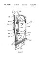
- FIG. 17 is a perspective view analogous to FIG. 1 of yet another alterative embodiment of the present invention in which a modified filling tube is utilized in the FFS machine;
- FIG. 18 is a side elevational view of the FFS machine of FIG. 17.
- FIG. 19 is a cross-sectional view taken as indicated by lines 19--19 of FIG. 18;
- FIG. 20 is a cross-sectional view taken as indicated by lines 20--20 of FIG. 18;
- FIG. 21 is a cross-sectional view taken as indicated by lines 21--21 of FIG. 18;
- FIG. 22 is a cross-sectional view taken as indicated by lines 22--22 of FIG. 18.
- FIG. 1 wherein the filling tube 20 of a conventional vertical form-fill-and-seal (FFS) machine 22 is depicted.
- FFS vertical form-fill-and-seal
- a continuous supply of a film 24 is brought from a supply roll about suitable guides to be wrapped into a tube 26 about the filling tube 20.
- the lateral edges 28 thereof are overlapped and a longitudinal seam is formed by a heat sealing bar, behind the filling tube 20 and not visible in the figure, in a manner that is well known to those of ordinary skill in the art, so as to transform the film 24 into a tube 26 about the filling tube 20.
- Transverse seams 24 are formed by heat sealing bars 32, which seal the bottom of the tube 26, as well as the top of the bag made immediately therebefore, following each incremental advance thereof.
- a predetermined quantity of product (not shown) is dropped through the filling tube 20 following each production of a transverse seam by heat sealing bars 32.
- the heat sealing bars 32 also separate each filled and sealed bag from the bottom of the tube 26.
- a zipper strip 34 is fed from a supply roll (not shown) and around a guide roller 36, below which may be a zipper separator 38, a disengaging and if required also a cutting instrument which separates the zipper strip 34 longitudinally into two portions, which may be a male profile 40 and a female profile 42, but which in general are two mutually interlockable profiles.
- the male profile 40 and female profile 42 are each guided into longitudinal grooves 44, which are cut into the surface of a curved plate 46 attached to the filling tube 20, within the tube 26 formed by film 24.
- An intermediate groove 44, between those provided for the male profile 40 and the female profile 42, may be provided for a tear string 48, which may be introduced from a spool 50.
- the zipper strip 34 and tear string 48 may be formed of a thermoplastic material, such as polyethylene.
- the film 24 may be of polyethylene or of a similar thermoplastic material, so that the zipper strip 34 material and tear string 48 may be heat-bonded thereto.
- the tear string 48 may be formed of string or of some other material encased in polyethylene.
- FIG. 2 is a cross section of the FFS machine 22 taken as indicated by line 2--2 in FIG. 1.
- Curved plate 46 in addition to longitudinal grooves 44, may be provided with a hot air channel 52, which, as will be later indicated, may discharge bursts of hot air between the profiles 40, 42 to soften them at points where heat sealing bars 32 will subsequently make a transverse seam across them, or may discharge a continuous stream of hot air onto the entire profiles 40, 42, as is described in copending patent applications U.S. Ser. No. 039,644 and U.S. Ser. No. 065,668 respectively. In either case, the hot air may be applied at the point where the profiles 40, 42 will be interlocked with one another.
- Longitudinal grooves 44 are provided to guide male profile 40, female profile 42 and tear string 48 on the inside of the tube 26 of film 24.
- Guide rolls 54 ensure that male profile 40 and female profile 42 remain within their respective longitudinal grooves 44.
- FIG. 3 is a cross section of the FFS machine 22 taken as indicated by line 3--3 in FIG. 1.
- Heat sealing bars 56 seal, bond, or weld the male profile 40 and the female profile 42 to the inside surface of the tube 26 of film 24. If necessary, another heat sealing bar may be used to attach the tear string 48 to the tube 26.
- an additional pair of guide rolls 58 may be provided below heat sealing bars 56 on the FFS machine 22 to ensure that the male profile 40 and the female profile 42 remain guided within longitudinal grooves 44.
- a forming plate 60 whose purpose is to gradually fold the film 24 in the vicinity of the male profile 40 and female profile 42 to permit the profiles 40, 42 to be interlocked with one another.
- FIG. 4 is a cross section of the FFS machine 22 taken as indicated by line 4--4 in FIG. 1.
- hot air channel 52 continues from curved plate 46 into forming plate 60.
- the tube 26 of film 24 proceeds downward through the space between the forming plate 60 and the forming shields 62.
- Longitudinal grooves 44 continue from the curved plate 46 to the forming plate 60 to guide the male profile 40, the female profile 42 and the tear string 48.
- still another pair of guide rolls 64 may be disposed at the bottom of the forming plate 60 to ensure that male profile 40 and female profile 42 are maintained in their respective longitudinal grooves 44 and facing one another, so that they will be in a position to be interlocked with one another below the forming plate 60.
- FIG. 7 is a cross section of the FFS machine 22 taken as indicated by line 7--7 in FIG. 1 below the forming pate 60. There, closing rolls 66 interlock male profile 40 into female profile 42.
- FIG. 8 is a cross section taken as indicated by line 8--8 in FIG. 6.
- guide rolls 64 ensure that male profile 40 and female profile 42 stay in their respective longitudinal grooves 44 on opposite sides of the forming plate 60.
- the forming plate 60 tapers and longitudinal grooves 44 merge into one another at the tapered end 68 to permit the male profile 40 to be inserted into the female profile 42.
- Hot air channel 52 also ends at the tapered end 68, so that hot air blasts may be directed onto the inside of profiles 40, 42 to soften them, as may be required, at the locations of transverse seams, to be provided subsequently by heat seal bars 32, or so that a stream of hot air may be continuously supplied to soften the profiles 40, 42.
- Closing rolls 66 interlock the profiles 40, 42.
- the present discussion has illustrated the use of string profiles, that is, male profile 40 and female profile 42 having no webs, either short or long, attached thereto.
- the present invention can be adapted for the use of profiles having webs, and of profiles which are joined to each other by a central web.
- a zipper strip 34 having a central or peripheral webs would permit the present invention to be adapted for the use of profiles having long (wide) or short (narrow) webs.
- the zipper may be delivered open, in which case the separator 38 would not be required.
- a closure 70 includes a male profile member 72, a female profile member 74, a tear string 76, a central web 78, and two peripheral webs 80.
- Closure 70 may be introduced into FFS machine 22 instead of zipper strip 34, and, if in an open configuration with the removal of zipper separator 38, may be used in the practice of the present invention.
- FIG. 10 is a cross section of a bag 82 made in accordance with the present invention.
- Male profile 40 and female profile 42 are so-called string profiles having webs of minimal size.
- Tear string 48 is disposed in the fold between the male profile 40 and female profile 42.
- a longitudinal seam 84 is formed where the lateral edges 28 of the film 24 are overlapped and bonded, welded or otherwise sealed together.
- FIG. 11 is a cross section of a bag 90 made using closure 70, previously shown above in FIG. 9.
- closure 70 having male profile member 72, female profile member 74, tear string 76, central web 78 and peripheral webs 80, is bonded to the inside of the film 24.
- closure 70 to the inside of tube 26 of film 24 may be accomplished in the manner shown in FIG. 12, which is a cross section of the FFS machine 22 analogous to FIG. 3. It will be noted, when comparing FIG. 12 to that earlier figure, that heat sealing bar 100, spanning the entire width of closure 70, has been substituted for the pair of heat sealing bars 56.
- closure 70 is illustrated in FIGS. 13 and 14, the former of which is a cross section of a bag 102 wherein only a portion of closure 70 is sealed to the inside of film 24.
- FIG. 14 is a cross section of the FFS machine 22 analogous to that provided in FIGS. 3 and 12, the bonding of closure 70 to the inside of tube 26 of film 24 may be carried out for somewhat less than the width of closure 70. This leaves a portion of central web 78, in this instance that portion having male profile portion 72, unbonded to the film 24. As a consequence, bag 102 will be provided with a hinge 106 between film 24 and the unbonded portion of profile 70. Longitudinal seam 104 is formed where the lateral edges 28 of film 24 are welded to one another.
- FIG. 15 is a cross section of a bag 112 made in accordance with yet another embodiment of the present invention.
- Bag 112 has a male profile 116 with an adjacent web 118 and a female profile 120 with an adjacent web 122.
- Male and female profiles 116, 120 with their respective webs 118, 122 may be provided initially in the form of a strip analogous to zipper strip 34 previously shown.
- Male and female profiles 116, 120 may be adjacent to each other on such a strip, or may be separated by a central web.
- the webs 118, 122 will be as shown in FIG. 15 farther from tear string 48 than male and female profiles 116, 120, or closer to the tear string 48 than the profiles 116, 120.
- longitudinal seam 114 is formed where lateral edges 28 of film 24 are overlapped and sealed to one another.
- FIG. 16 is a cross section of FFS machine 22, analogous to FIGS. 2 and 9, where bags 112 of FIG. 15 are being produced.
- Male profile 116 with adjacent web 118 and female profile 120 with adjacent web 122 are guided in grooves 44 in curved plate 46.
- Male and female profiles 116, 120 may initially have been part of a single zipper strip, like zipper strip 34 in FIG. 1 but having additional webs 118, 122, wherein the single zipper strip was cut longitudinally by zipper by a cutter located at separator 38.
- male profile 116 and female profile 120 may be adjacent to one another, webs 118, 122 being on the peripheral sides of the strip, to produce the configuration shown in FIG. 16, or male and female profiles 116, 120 may be separated by a central web, which, when cut longitudinally, produces webs 118, 122.
- profiles 116 and 120 with their respective webs may be delivered in joined configuration and disengaged by separator 38.
- film 224 is depicted being wrapped about fill tube 220 of FFS machine 222 to form tube 226 in the manner previously described.
- the tube 226 is filled with product and sealed into bags by sealing bars 232.
- uninterlocked male profile 240 and 242 are guided into longitudinal grooves 244 which are cut into fill tube 220 (or may be formed in a plate attached to the fill tube).
- an additional groove for a tear string may also be provided.
- Guide rolls 254 ensure that the male profile 240 and female profile 242 remain within their respective grooves 244 as shown in FIG. 19 and heat sealing bars 256 bond or weld the profiles 240, 242 to the inside surface of the film tube 226.
- An additional guide roll 258 ensures that the profiles 240, 242 remain in their respective grooves 244 after being attached to the film.
- the present embodiment of the invention as shown in FIGS. 17 through 22 differs from previously described in that the fill tube 220 tapers inwardly into a funnel shape 270 with the area adjacent the profiles gradually forming a finger 262 protruding from said funnel the groove 224 are continued into this finger.
- a pair of forming shields 260 are provided below guide rolls 258 and extend to the lower end 274 of the fill tube 220.
- the profiles are kept within the grooves 244 by said forming shields.
- the grooves in the finger 262 have positioned the profiles in facing relationship, so that a pair of closing rolls 272, just below the end of the finger, press the profiles together into interlocking relationship. Thereafter the tube is sealed and cut by cross bars 232 in the manner previously discussed.
Abstract
Description
Claims (25)
Priority Applications (3)
| Application Number | Priority Date | Filing Date | Title |
|---|---|---|---|
| US08/254,239 US5425216A (en) | 1994-06-06 | 1994-06-06 | Method of making reclosable plastic bags on a form, fill and seal machine with open zipper profiles |
| DE69503976T DE69503976D1 (en) | 1994-06-06 | 1995-06-06 | Process for the production of reclosable plastic bags on a form, fill and seal machine with open zipper profiles |
| EP95401305A EP0686557B1 (en) | 1994-06-06 | 1995-06-06 | Method of making reclosable plastic bags on a form, fill and seal machine with open zipper profiles |
Applications Claiming Priority (1)
| Application Number | Priority Date | Filing Date | Title |
|---|---|---|---|
| US08/254,239 US5425216A (en) | 1994-06-06 | 1994-06-06 | Method of making reclosable plastic bags on a form, fill and seal machine with open zipper profiles |
Publications (1)
| Publication Number | Publication Date |
|---|---|
| US5425216A true US5425216A (en) | 1995-06-20 |
Family
ID=22963489
Family Applications (1)
| Application Number | Title | Priority Date | Filing Date |
|---|---|---|---|
| US08/254,239 Expired - Fee Related US5425216A (en) | 1994-06-06 | 1994-06-06 | Method of making reclosable plastic bags on a form, fill and seal machine with open zipper profiles |
Country Status (3)
| Country | Link |
|---|---|
| US (1) | US5425216A (en) |
| EP (1) | EP0686557B1 (en) |
| DE (1) | DE69503976D1 (en) |
Cited By (65)
| Publication number | Priority date | Publication date | Assignee | Title |
|---|---|---|---|---|
| US5551208A (en) * | 1995-05-31 | 1996-09-03 | Minigrip, Inc. | Method for applying zipper to film at tube on a form-fill-and-seal |
| US5557907A (en) * | 1995-02-24 | 1996-09-24 | Illinois Tool Works Inc. | Transverse zipper system |
| US5735106A (en) * | 1996-11-26 | 1998-04-07 | The Procter & Gamble Company | Continuous process for packaging compressible products |
| US5768861A (en) * | 1995-10-26 | 1998-06-23 | Robert Bosch Gmbh | Bag forming, filling, and sealing machine |
| US5875611A (en) * | 1997-02-25 | 1999-03-02 | Illinois Tool Works Inc. | Offset sealing method for plastic films |
| US5894707A (en) * | 1996-05-10 | 1999-04-20 | Reynolds Consumer Products, Inc. | Method for making flexible package with hanghole and tear string |
| US5938337A (en) * | 1998-10-13 | 1999-08-17 | Tenneco Packaging Inc. | Bottom filled, bottom-gusseted bag and method of making the same |
| US5956924A (en) * | 1997-11-07 | 1999-09-28 | Rcl Corporation | Method and apparatus for placing a product in a flexible recloseable container |
| US6071011A (en) | 1999-08-12 | 2000-06-06 | Tenneco Packaging, Inc. | Fill-through-the-top package |
| US6098380A (en) * | 1996-12-23 | 2000-08-08 | Lipton, Division Of Conopco, Inc. | Web shaping method and means |
| US6149302A (en) * | 1999-05-05 | 2000-11-21 | Taheri; Nossi | Plastic bag with tamper-evident closure |
| US6217216B1 (en) | 1996-02-22 | 2001-04-17 | Nossi Taheri | Reclosable plastic bag with non-perforated tear zone |
| US6216423B1 (en) | 1997-11-07 | 2001-04-17 | Huntsman Kcl Corporation | Method and apparatus for placing a product in a flexible recloseable container |
| US6286189B1 (en) | 1999-05-10 | 2001-09-11 | Pactiv Corporation | Zipper and zipper arrangements and methods of manufacturing the same |
| US6289561B1 (en) | 1999-05-10 | 2001-09-18 | Alexander R. Provan | Assembly and accumulation of sliders for profiled zippers |
| EP1026077A3 (en) * | 1999-02-04 | 2001-10-17 | Illinois Tool Works Inc. | Form-fill-and-seal machine |
| US6327754B1 (en) | 1999-05-10 | 2001-12-11 | Pactiv Corporation | Fastener with slider thereon for use in manufacturing recloseable bags |
| WO2002012064A1 (en) * | 2000-08-10 | 2002-02-14 | Pactiv Corporation | Method and apparatus for making reclosable plastic bags using a pre-applied slider-operated fastener |
| US6389780B1 (en) | 2000-08-10 | 2002-05-21 | Pactiv Corporation | Zipper bag form, fill and seal machine and method |
| US20020139083A1 (en) * | 2001-03-28 | 2002-10-03 | Tna Australia Pty Limited | Method and apparatus to aid in forming a package |
| US6470551B1 (en) | 2000-08-10 | 2002-10-29 | Pactiv Corporation | Method of making a fasteners arrangement with notches at spaced preseals |
| US6494018B1 (en) | 2000-08-09 | 2002-12-17 | Pactiv Corporation | Method and apparatus for guiding a fastener in a bag making machine |
| US6508969B1 (en) | 2000-08-10 | 2003-01-21 | Pactiv Corporation | Injection-molded end stop for a slider-operated fastener |
| US6526726B1 (en) | 2000-08-10 | 2003-03-04 | Pactiv Corporation | Method of applying a slider to a fastener-carrying plastic web |
| US6588177B1 (en) * | 2002-02-04 | 2003-07-08 | Reynolds Consumer Products, Inc. | Method and apparatus for forming a reclosable package |
| US6611996B2 (en) | 2001-07-02 | 2003-09-02 | Pactiv Corporation | Slider for reclosable fastener |
| US20030208989A1 (en) * | 2002-02-21 | 2003-11-13 | Thomas Toby R. | Process for attaching slider-operated closure on form-fill-seal packaging machinery |
| US20030217531A1 (en) * | 2002-05-24 | 2003-11-27 | Keen Bruce W. | Vertical form, fill, and seal apparatus for making several types of packages |
| US20040016205A1 (en) * | 2002-04-18 | 2004-01-29 | Pro-Pac Services., Inc. | Packaging machine for producing reclosable packages |
| US6713152B2 (en) | 2001-09-07 | 2004-03-30 | Pactiv Corporation | Fins and profiles for plastic bags |
| US6715262B2 (en) * | 2001-04-27 | 2004-04-06 | Illinois Tool Works Inc. | Form, fill and seal method and apparatus for forming reclosable bags |
| US20040154271A1 (en) * | 2003-01-06 | 2004-08-12 | Rietjens Peter Wilhelmus Henricus | Device and method for manufacturing reclosable packagings |
| US6780146B2 (en) | 2002-09-17 | 2004-08-24 | Pactiv Corporation | Methods for applying sliders to reclosable plastic bags |
| US20040220034A1 (en) * | 2003-04-30 | 2004-11-04 | Melchoir Greg W. | Method and apparatus for manufacturing a resealable package |
| US20040226849A1 (en) * | 2002-03-18 | 2004-11-18 | Brenkus Frank Mathew | Double-bag package and perforation knife |
| US20050008268A1 (en) * | 2002-05-20 | 2005-01-13 | Plourde Eric Paul | Packages incorporating easy-open strips and methods of manufacture |
| US20050034422A1 (en) * | 1998-04-20 | 2005-02-17 | Steven Ausnit | Process and apparatus for forming packaging bags with a fastener |
| US20050115211A1 (en) * | 2002-03-18 | 2005-06-02 | Knoerzer Anthony R. | Vertical stand-up pouch with zipper seal quick change module |
| US20050157959A1 (en) * | 2004-01-16 | 2005-07-21 | Johnson Joel L. | Easy-open shrouded slider-zipper assembly for reclosable bag |
| US20050227845A1 (en) * | 2002-06-19 | 2005-10-13 | Mars Incorporated | Method of manufacturing thin-walled containers from film webs and production facility for carrying out the method |
| US20050238766A1 (en) * | 2002-03-18 | 2005-10-27 | Henderson Eric T | Bandolier format packaging |
| US7101079B2 (en) | 1999-05-11 | 2006-09-05 | Sargento Foods, Inc. | Resealable bag for filling with food product(s) and method |
| US20060207221A1 (en) * | 2005-03-15 | 2006-09-21 | Illinois Tool Works Inc. | Vertical form and fill seal method and apparatus using two sheets of web |
| US20060210202A1 (en) * | 2005-03-15 | 2006-09-21 | Plourde Eric P | Reclosable packages with front panel opening and related methods of manufacture |
| US7254873B2 (en) | 1998-06-04 | 2007-08-14 | Illinois Tool Works, Inc. | Scored tamper evident fastener tape |
| US7254930B2 (en) | 2002-03-18 | 2007-08-14 | Frito-Lay North America, Inc. | Stationary tucker bar mechanism |
| US7299608B2 (en) | 2002-03-18 | 2007-11-27 | Frito-Lay North America, Inc. | Quick change module with adjustable former attachments |
| US7305805B2 (en) | 2005-09-22 | 2007-12-11 | Frito-Lay North America, Inc. | Method for making a flexible reclosable package |
| US20070289254A1 (en) * | 2006-06-12 | 2007-12-20 | Illinois Tool Works Inc. | Concave zipper and method of sealing |
| US20070297698A1 (en) * | 2006-06-23 | 2007-12-27 | Edward Alan Berich | Reclosable Storage Bag Closure With Internal Valving |
| WO2009000510A2 (en) * | 2007-06-28 | 2008-12-31 | Reifenhäuser GmbH & Co. KG Maschinenfabrik | Device for producing blown films |
| US20090097782A1 (en) * | 2007-10-15 | 2009-04-16 | Illinois Tool Works Inc. | Method for producing perforated zipper for transverse direction zipper applicator |
| US7552574B2 (en) | 2002-03-18 | 2009-06-30 | Frito-Lay North America, Inc. | Variable tension gusseting system |
| US7665192B2 (en) | 2002-03-01 | 2010-02-23 | Pactiv Corporation | Reclosable fasteners or zippers for use with polymeric bags |
| US20110079536A1 (en) * | 2002-08-08 | 2011-04-07 | Cappel Craig E | Reclosable package having an accessible zipper and method for making the same |
| US8070359B2 (en) | 2007-05-15 | 2011-12-06 | Thunderbird Global Enterprises, Llc | Plastic bag with pour spout and reinforced bottom end |
| US20120225763A1 (en) * | 2011-03-02 | 2012-09-06 | Ishida Co., Ltd. | Bag-making packaging machine |
| US8523437B2 (en) | 1999-05-11 | 2013-09-03 | Sargento Foods, Inc. | Resealable bag for filling with food product (s) and method |
| EP2829391A1 (en) * | 2013-07-10 | 2015-01-28 | Totani Corporation | Fastener material advancing direction changing apparatus |
| US20150183176A1 (en) * | 2013-12-26 | 2015-07-02 | Totani Corporation | Plastic bag making apparatus |
| US20160023789A1 (en) * | 2013-10-23 | 2016-01-28 | Guangzhou Yilugao Packing Machinery Technic Co., Ltd | Bag forming device and packaging machine comprising the same |
| US10689137B2 (en) | 2017-05-22 | 2020-06-23 | Triangle Package Machinery Company | Continuous vertical form, fill and seal machine and method for making reclosable packages |
| CN113939456A (en) * | 2019-06-27 | 2022-01-14 | 利乐拉瓦尔集团及财务有限公司 | A package sealing control system, an upgrade kit, and a method for monitoring and selectively controlling the longitudinal sealing of packaging material in a packaging and filling machine |
| WO2022096453A1 (en) * | 2020-11-04 | 2022-05-12 | Gea Food Solutions Weert B.V. | Vertical flow wrapper with an asymmetrical form shoulder |
| US11542053B2 (en) * | 2017-05-10 | 2023-01-03 | Gea Food Solutions Weert B.V. | Heating means for a flow wrapper |
Citations (21)
| Publication number | Priority date | Publication date | Assignee | Title |
|---|---|---|---|---|
| US3815317A (en) * | 1973-03-08 | 1974-06-11 | F Toss | Method and mechanism for making filled bags |
| US4355494A (en) * | 1979-08-06 | 1982-10-26 | Minigrip, Inc. | Reclosable bags, apparatus and method |
| US4601694A (en) * | 1982-04-16 | 1986-07-22 | Minigrip, Inc. | Thin wall reclosable bag material and method of making same |
| US4625496A (en) * | 1985-06-11 | 1986-12-02 | Minigrip, Inc. | Method and apparatus for forming a reclosable package |
| US4646511A (en) * | 1985-10-15 | 1987-03-03 | Signode Corporation | Turning panel flap of zipper-equipped package material |
| US4698954A (en) * | 1986-07-25 | 1987-10-13 | The Dow Chemical Company | Guide for zippered film in a form, fill and seal packaging machine |
| US4709533A (en) * | 1986-12-22 | 1987-12-01 | Minigrip, Inc. | Method and apparatus for making reclosable bags in a form, fill and seal machine |
| US4727709A (en) * | 1986-07-25 | 1988-03-01 | The Dow Chemical Company | Steering, joining and guiding mechanism for zippered film |
| US4790126A (en) * | 1987-06-29 | 1988-12-13 | Minigrip Inc. | Fill and seal machine for reclosable bags |
| US4829745A (en) * | 1987-12-07 | 1989-05-16 | The Dow Chemical Company | Tube spreader for removing wrinkles in tube stock |
| US4840012A (en) * | 1987-12-10 | 1989-06-20 | Zip-Pak Incorporated | Zippered film feed |
| US4869048A (en) * | 1987-06-29 | 1989-09-26 | Zip-Pak Incorporated | Stretcher for package forming |
| US4876842A (en) * | 1988-01-15 | 1989-10-31 | Minigrip, Inc. | Method of and apparatus for packaging product masses in a form, fill and seal machine |
| US4894975A (en) * | 1988-03-09 | 1990-01-23 | Minigrip, Inc. | Method and apparatus for making reclosable bags with fastener strips in a form fill and seal machine |
| US4909017A (en) * | 1989-07-28 | 1990-03-20 | Minigrip, Inc. | Reclosable bag material, method and apparatus |
| US4941307A (en) * | 1989-04-24 | 1990-07-17 | Zip-Pak Incorporated | Zipper guide system for form tooling |
| US4993212A (en) * | 1990-02-01 | 1991-02-19 | Zip-Pak Incorporated | Method and apparatus for guiding a zippered film in form, fill and seal package making machines |
| US5027584A (en) * | 1990-01-12 | 1991-07-02 | Illinois Tool Works, Inc. | Method and apparatus for unfolding folded zipper film |
| US5042224A (en) * | 1990-02-01 | 1991-08-27 | Zip-Pak Incorporated | Zipper tracking in form, fill and seal package machines |
| US5072571A (en) * | 1990-02-26 | 1991-12-17 | Zip-Pak Incorporated | Zippered film plural sheet strip guide system and method for zippered film for form, fill and seal package making machines |
| US5127208A (en) * | 1990-10-19 | 1992-07-07 | Reynolds Consumer Products Inc. | Method and apparatus for forming a reclosable package |
Family Cites Families (3)
| Publication number | Priority date | Publication date | Assignee | Title |
|---|---|---|---|---|
| US3964493A (en) | 1972-09-07 | 1976-06-22 | Baker-Alpha Corporation | Cigarette filter |
| US5046300A (en) | 1990-10-19 | 1991-09-10 | Reynolds Consumer Products, Inc. | Method and apparatus for forming a reclosable package |
| US6566893B2 (en) | 1997-02-28 | 2003-05-20 | Ust Umweltsensortechnik Gmbh | Method and arrangement for monitoring surfaces for the presence of dew |
-
1994
- 1994-06-06 US US08/254,239 patent/US5425216A/en not_active Expired - Fee Related
-
1995
- 1995-06-06 EP EP95401305A patent/EP0686557B1/en not_active Expired - Lifetime
- 1995-06-06 DE DE69503976T patent/DE69503976D1/en not_active Expired - Lifetime
Patent Citations (23)
| Publication number | Priority date | Publication date | Assignee | Title |
|---|---|---|---|---|
| US3815317A (en) * | 1973-03-08 | 1974-06-11 | F Toss | Method and mechanism for making filled bags |
| US4355494A (en) * | 1979-08-06 | 1982-10-26 | Minigrip, Inc. | Reclosable bags, apparatus and method |
| US4601694A (en) * | 1982-04-16 | 1986-07-22 | Minigrip, Inc. | Thin wall reclosable bag material and method of making same |
| US4625496A (en) * | 1985-06-11 | 1986-12-02 | Minigrip, Inc. | Method and apparatus for forming a reclosable package |
| US4646511A (en) * | 1985-10-15 | 1987-03-03 | Signode Corporation | Turning panel flap of zipper-equipped package material |
| US4698954A (en) * | 1986-07-25 | 1987-10-13 | The Dow Chemical Company | Guide for zippered film in a form, fill and seal packaging machine |
| US4727709A (en) * | 1986-07-25 | 1988-03-01 | The Dow Chemical Company | Steering, joining and guiding mechanism for zippered film |
| US4709533A (en) * | 1986-12-22 | 1987-12-01 | Minigrip, Inc. | Method and apparatus for making reclosable bags in a form, fill and seal machine |
| US4869048A (en) * | 1987-06-29 | 1989-09-26 | Zip-Pak Incorporated | Stretcher for package forming |
| US4790126A (en) * | 1987-06-29 | 1988-12-13 | Minigrip Inc. | Fill and seal machine for reclosable bags |
| US4829745A (en) * | 1987-12-07 | 1989-05-16 | The Dow Chemical Company | Tube spreader for removing wrinkles in tube stock |
| US4840012A (en) * | 1987-12-10 | 1989-06-20 | Zip-Pak Incorporated | Zippered film feed |
| US4876842A (en) * | 1988-01-15 | 1989-10-31 | Minigrip, Inc. | Method of and apparatus for packaging product masses in a form, fill and seal machine |
| US4894975A (en) * | 1988-03-09 | 1990-01-23 | Minigrip, Inc. | Method and apparatus for making reclosable bags with fastener strips in a form fill and seal machine |
| US4894975B1 (en) * | 1988-03-09 | 1991-12-03 | Minigrip Inc | |
| US4941307A (en) * | 1989-04-24 | 1990-07-17 | Zip-Pak Incorporated | Zipper guide system for form tooling |
| US4909017A (en) * | 1989-07-28 | 1990-03-20 | Minigrip, Inc. | Reclosable bag material, method and apparatus |
| US4909017B1 (en) * | 1989-07-28 | 1999-02-09 | Minigrip Inc | Reclosable bag material method and apparatus |
| US5027584A (en) * | 1990-01-12 | 1991-07-02 | Illinois Tool Works, Inc. | Method and apparatus for unfolding folded zipper film |
| US4993212A (en) * | 1990-02-01 | 1991-02-19 | Zip-Pak Incorporated | Method and apparatus for guiding a zippered film in form, fill and seal package making machines |
| US5042224A (en) * | 1990-02-01 | 1991-08-27 | Zip-Pak Incorporated | Zipper tracking in form, fill and seal package machines |
| US5072571A (en) * | 1990-02-26 | 1991-12-17 | Zip-Pak Incorporated | Zippered film plural sheet strip guide system and method for zippered film for form, fill and seal package making machines |
| US5127208A (en) * | 1990-10-19 | 1992-07-07 | Reynolds Consumer Products Inc. | Method and apparatus for forming a reclosable package |
Cited By (149)
| Publication number | Priority date | Publication date | Assignee | Title |
|---|---|---|---|---|
| US5557907A (en) * | 1995-02-24 | 1996-09-24 | Illinois Tool Works Inc. | Transverse zipper system |
| US5592802A (en) * | 1995-02-24 | 1997-01-14 | Illinois Tool Works, Inc. | Transverse zipper system |
| US5551208A (en) * | 1995-05-31 | 1996-09-03 | Minigrip, Inc. | Method for applying zipper to film at tube on a form-fill-and-seal |
| US5768861A (en) * | 1995-10-26 | 1998-06-23 | Robert Bosch Gmbh | Bag forming, filling, and sealing machine |
| US6217216B1 (en) | 1996-02-22 | 2001-04-17 | Nossi Taheri | Reclosable plastic bag with non-perforated tear zone |
| US5894707A (en) * | 1996-05-10 | 1999-04-20 | Reynolds Consumer Products, Inc. | Method for making flexible package with hanghole and tear string |
| US5735106A (en) * | 1996-11-26 | 1998-04-07 | The Procter & Gamble Company | Continuous process for packaging compressible products |
| US6098380A (en) * | 1996-12-23 | 2000-08-08 | Lipton, Division Of Conopco, Inc. | Web shaping method and means |
| US5875611A (en) * | 1997-02-25 | 1999-03-02 | Illinois Tool Works Inc. | Offset sealing method for plastic films |
| US20060112664A1 (en) * | 1997-11-07 | 2006-06-01 | Thieman Ronald G | Method and apparatus for placing a product in a flexible recloseable container |
| US20050003940A1 (en) * | 1997-11-07 | 2005-01-06 | Thieman Ronald G. | Method and apparatus for placing a product in a flexible recloseable container |
| US7383675B2 (en) | 1997-11-07 | 2008-06-10 | Illinois Tool Works, Inc. | Method and apparatus for placing a product in a flexible recloseable container |
| US7320662B2 (en) | 1997-11-07 | 2008-01-22 | Illinois Tool Works, Inc. | Method for manufacturing a flexible recloseable container |
| US6209287B1 (en) | 1997-11-07 | 2001-04-03 | Huntsman Kcl Corporation | Method and apparatus for placing a product in a flexible recloseable container |
| US5956924A (en) * | 1997-11-07 | 1999-09-28 | Rcl Corporation | Method and apparatus for placing a product in a flexible recloseable container |
| US6216423B1 (en) | 1997-11-07 | 2001-04-17 | Huntsman Kcl Corporation | Method and apparatus for placing a product in a flexible recloseable container |
| US7540662B2 (en) | 1997-11-07 | 2009-06-02 | Illinois Tool Works Inc. | Flexible package including a docking station formed from a plurality of closely spaced slits |
| US8127517B2 (en) | 1997-11-07 | 2012-03-06 | Illinois Tool Works Inc. | Method and apparatus for placing a product in a flexible recloseable container |
| US20030220180A1 (en) * | 1997-11-07 | 2003-11-27 | Thieman Ronald G. | Method and apparatus for placing a product in a flexible recloseable container |
| US20030220179A1 (en) * | 1997-11-07 | 2003-11-27 | Thieman Ronald G. | Method and apparatus for placing a product in a flexible recloseable container |
| US6499272B2 (en) | 1997-11-07 | 2002-12-31 | Huntsman Kcl Corporation | Method for placing a product in a flexible recloseable container |
| US20040074058A1 (en) * | 1997-11-07 | 2004-04-22 | Thieman Ronald G. | Method and apparatus for placing a product in a flexible recloseable container |
| US6918230B2 (en) | 1997-11-07 | 2005-07-19 | Illinois Tool Works Inc. | Method and apparatus for placing a product in a flexible recloseable container |
| US20030074861A1 (en) * | 1997-11-07 | 2003-04-24 | Thieman Ronald G. | Method and apparatus for placing a product in a flexible recloseable container |
| US6363692B2 (en) | 1997-11-07 | 2002-04-02 | Pliant Corporation | Method and apparatus for placing a product in a flexible recloseable container |
| US6907713B2 (en) | 1997-11-07 | 2005-06-21 | Pliant Corporation | Method and apparatus for placing a product in a flexible recloseable container |
| US20060096245A1 (en) * | 1997-11-07 | 2006-05-11 | Thieman Ronald G | Method and apparatus for placing a product in a flexible recloseable container |
| US6438926B1 (en) | 1997-11-07 | 2002-08-27 | Pliant Corporation | Method and apparatus for placing a product in a flexible recloseable container |
| US6962034B2 (en) | 1997-11-07 | 2005-11-08 | Illinois Tool Works Inc. | Apparatus for flexible recloseable containers |
| US6925779B2 (en) | 1997-11-07 | 2005-08-09 | Illinois Tool Works Inc. | Method and apparatus for placing a product in a flexible recloseable container |
| US7059099B2 (en) * | 1998-04-20 | 2006-06-13 | Illinois Tool Works Inc. | Process and apparatus for forming packaging bags with a fastener |
| US20050034422A1 (en) * | 1998-04-20 | 2005-02-17 | Steven Ausnit | Process and apparatus for forming packaging bags with a fastener |
| US7254873B2 (en) | 1998-06-04 | 2007-08-14 | Illinois Tool Works, Inc. | Scored tamper evident fastener tape |
| US5938337A (en) * | 1998-10-13 | 1999-08-17 | Tenneco Packaging Inc. | Bottom filled, bottom-gusseted bag and method of making the same |
| EP1026077A3 (en) * | 1999-02-04 | 2001-10-17 | Illinois Tool Works Inc. | Form-fill-and-seal machine |
| US6149302A (en) * | 1999-05-05 | 2000-11-21 | Taheri; Nossi | Plastic bag with tamper-evident closure |
| USRE44934E1 (en) | 1999-05-10 | 2014-06-10 | Reynolds Presto Products Inc. | Zipper and zipper arrangements and methods of manufacturing the same |
| US6327754B1 (en) | 1999-05-10 | 2001-12-11 | Pactiv Corporation | Fastener with slider thereon for use in manufacturing recloseable bags |
| US6292986B1 (en) | 1999-05-10 | 2001-09-25 | Alexander R. Provan | Assembly and accumulation of sliders for profiled zippers |
| US6289561B1 (en) | 1999-05-10 | 2001-09-18 | Alexander R. Provan | Assembly and accumulation of sliders for profiled zippers |
| US6347437B2 (en) | 1999-05-10 | 2002-02-19 | Pactiv Corporation | Zipper and zipper arrangements and methods of manufacturing the same |
| US6286189B1 (en) | 1999-05-10 | 2001-09-11 | Pactiv Corporation | Zipper and zipper arrangements and methods of manufacturing the same |
| US6427421B1 (en) | 1999-05-10 | 2002-08-06 | Pactiv Corporation | Method of manufacturing recloseable packages |
| US8523437B2 (en) | 1999-05-11 | 2013-09-03 | Sargento Foods, Inc. | Resealable bag for filling with food product (s) and method |
| US7101079B2 (en) | 1999-05-11 | 2006-09-05 | Sargento Foods, Inc. | Resealable bag for filling with food product(s) and method |
| US6071011A (en) | 1999-08-12 | 2000-06-06 | Tenneco Packaging, Inc. | Fill-through-the-top package |
| US6279298B1 (en) | 1999-08-12 | 2001-08-28 | Pactiv Corporation | Fill-through-the-top package and method and apparatus for making the same |
| US6148588A (en) | 1999-08-12 | 2000-11-21 | Pactiv Corporation | Fill-through-the-top package and method and apparatus for making the same |
| US6494018B1 (en) | 2000-08-09 | 2002-12-17 | Pactiv Corporation | Method and apparatus for guiding a fastener in a bag making machine |
| US6508969B1 (en) | 2000-08-10 | 2003-01-21 | Pactiv Corporation | Injection-molded end stop for a slider-operated fastener |
| US6470551B1 (en) | 2000-08-10 | 2002-10-29 | Pactiv Corporation | Method of making a fasteners arrangement with notches at spaced preseals |
| WO2002012064A1 (en) * | 2000-08-10 | 2002-02-14 | Pactiv Corporation | Method and apparatus for making reclosable plastic bags using a pre-applied slider-operated fastener |
| US6662410B2 (en) | 2000-08-10 | 2003-12-16 | Pactiv Corporation | Injection-molded end stop for a slider-operated fastener |
| US6389780B1 (en) | 2000-08-10 | 2002-05-21 | Pactiv Corporation | Zipper bag form, fill and seal machine and method |
| US6622353B2 (en) | 2000-08-10 | 2003-09-23 | Pactiv Corporation | Slider-operated fastener with spaced notches and associated preseals |
| US7093409B2 (en) | 2000-08-10 | 2006-08-22 | Pactiv Corporation | Method and apparatus for making reclosable plastic bags using a pre-applied slider-operated fastener |
| US20050086911A1 (en) * | 2000-08-10 | 2005-04-28 | Dutt William M. | Method and apparatus for making reclosable plastic bags using a pre-applied slider-operated fastener |
| US6871473B1 (en) | 2000-08-10 | 2005-03-29 | Pactiv Corporation | Method and apparatus for making reclosable plastic bags using a pre-applied slider-operated fastener |
| US6526726B1 (en) | 2000-08-10 | 2003-03-04 | Pactiv Corporation | Method of applying a slider to a fastener-carrying plastic web |
| US20020139083A1 (en) * | 2001-03-28 | 2002-10-03 | Tna Australia Pty Limited | Method and apparatus to aid in forming a package |
| US6655110B2 (en) * | 2001-03-28 | 2003-12-02 | Tna Australia Pty Limited | Apparatus to aid in forming a package |
| US6715262B2 (en) * | 2001-04-27 | 2004-04-06 | Illinois Tool Works Inc. | Form, fill and seal method and apparatus for forming reclosable bags |
| US6611996B2 (en) | 2001-07-02 | 2003-09-02 | Pactiv Corporation | Slider for reclosable fastener |
| US6713152B2 (en) | 2001-09-07 | 2004-03-30 | Pactiv Corporation | Fins and profiles for plastic bags |
| US6588177B1 (en) * | 2002-02-04 | 2003-07-08 | Reynolds Consumer Products, Inc. | Method and apparatus for forming a reclosable package |
| WO2003066438A1 (en) * | 2002-02-04 | 2003-08-14 | Reynolds Consumer Products, Inc. | Method and apparatus for forming a reclosable package |
| US20050247027A1 (en) * | 2002-02-21 | 2005-11-10 | Thomas Toby R | Process for attaching slider operated closure on form-fill-seal packaging machinery |
| US20080072541A1 (en) * | 2002-02-21 | 2008-03-27 | Thomas Toby R | Process for making a recloseable package |
| US7779605B2 (en) | 2002-02-21 | 2010-08-24 | Pactiv Corporation | Unit operations on a web with attached zipper and method of performing the same |
| US20100279840A1 (en) * | 2002-02-21 | 2010-11-04 | Pactiv Corporation | Method of performing unit operations on a web with an attached zipper |
| US20050241274A1 (en) * | 2002-02-21 | 2005-11-03 | Thomas Toby R | Process for attaching slider operated closure on form-fill-seal packaging machinery |
| US20070113522A1 (en) * | 2002-02-21 | 2007-05-24 | Thomas Toby R | Process for making a recloseable package |
| US20030208989A1 (en) * | 2002-02-21 | 2003-11-13 | Thomas Toby R. | Process for attaching slider-operated closure on form-fill-seal packaging machinery |
| US20090127371A1 (en) * | 2002-02-21 | 2009-05-21 | Thomas Toby R | Process for making a recloseable package |
| US7665192B2 (en) | 2002-03-01 | 2010-02-23 | Pactiv Corporation | Reclosable fasteners or zippers for use with polymeric bags |
| US7904996B2 (en) | 2002-03-01 | 2011-03-15 | Pactiv Corporation | Reclosable fasteners or zippers for use with polymeric bags |
| US20050115211A1 (en) * | 2002-03-18 | 2005-06-02 | Knoerzer Anthony R. | Vertical stand-up pouch with zipper seal quick change module |
| US7197859B2 (en) * | 2002-03-18 | 2007-04-03 | Frito-Lay North American, Inc. | Vertical stand-up pouch with zipper seal quick change module |
| US20060140514A1 (en) * | 2002-03-18 | 2006-06-29 | Dierl Martin B | Vertical stand-up pouch with integrated reclose strip |
| US7552574B2 (en) | 2002-03-18 | 2009-06-30 | Frito-Lay North America, Inc. | Variable tension gusseting system |
| US20040226849A1 (en) * | 2002-03-18 | 2004-11-18 | Brenkus Frank Mathew | Double-bag package and perforation knife |
| US20090162496A1 (en) * | 2002-03-18 | 2009-06-25 | Frito-Lay North America, Inc. | Bandolier Format Packaging |
| US6886313B2 (en) | 2002-03-18 | 2005-05-03 | Frito-Lay North America, Inc. | Method and apparatus for making flat bottom bags |
| US8132395B2 (en) | 2002-03-18 | 2012-03-13 | Frito-Lay North America, Inc. | Variable tension gusseting system |
| US7299608B2 (en) | 2002-03-18 | 2007-11-27 | Frito-Lay North America, Inc. | Quick change module with adjustable former attachments |
| US20050238766A1 (en) * | 2002-03-18 | 2005-10-27 | Henderson Eric T | Bandolier format packaging |
| US7254930B2 (en) | 2002-03-18 | 2007-08-14 | Frito-Lay North America, Inc. | Stationary tucker bar mechanism |
| US7516596B2 (en) | 2002-03-18 | 2009-04-14 | Frito-Lay North America, Inc. | Bandolier format packaging |
| US20100011711A1 (en) * | 2002-03-18 | 2010-01-21 | Frito-Lay North America, Inc. | Variable Tension Gusseting System |
| US6935086B2 (en) | 2002-03-18 | 2005-08-30 | Frito-Lay North America, Inc. | Double-bag package and perforation knife |
| US20040016205A1 (en) * | 2002-04-18 | 2004-01-29 | Pro-Pac Services., Inc. | Packaging machine for producing reclosable packages |
| US6701695B1 (en) | 2002-04-18 | 2004-03-09 | Brian Douglas | Packaging machine for producing reclosable packages |
| US6868654B2 (en) | 2002-04-18 | 2005-03-22 | Pro-Pac Services, Inc. | Packaging machine for producing reclosable packages |
| US20050008268A1 (en) * | 2002-05-20 | 2005-01-13 | Plourde Eric Paul | Packages incorporating easy-open strips and methods of manufacture |
| US7395642B2 (en) * | 2002-05-20 | 2008-07-08 | Illinois Tool Works Inc. | Method of manufacturing packages incorporating easy-open strips |
| US20030217531A1 (en) * | 2002-05-24 | 2003-11-27 | Keen Bruce W. | Vertical form, fill, and seal apparatus for making several types of packages |
| US7285083B2 (en) * | 2002-06-19 | 2007-10-23 | Mars, Inc. | Method of manufacturing thin-walled containers from film webs and production facility for carrying out the method |
| US20050227845A1 (en) * | 2002-06-19 | 2005-10-13 | Mars Incorporated | Method of manufacturing thin-walled containers from film webs and production facility for carrying out the method |
| US20110079536A1 (en) * | 2002-08-08 | 2011-04-07 | Cappel Craig E | Reclosable package having an accessible zipper and method for making the same |
| US8448413B2 (en) | 2002-08-08 | 2013-05-28 | Reynolds Presto Products Inc. | Method for making reclosable package having an accessible zipper |
| US6780146B2 (en) | 2002-09-17 | 2004-08-24 | Pactiv Corporation | Methods for applying sliders to reclosable plastic bags |
| US20050022352A1 (en) * | 2002-09-17 | 2005-02-03 | Thomas Toby R. | Methods for applying sliders to reclosable plastic bags |
| US20050020424A1 (en) * | 2002-09-17 | 2005-01-27 | Thomas Toby R. | Methods for applying sliders to reclosable plastic bags |
| US20070199280A1 (en) * | 2002-09-17 | 2007-08-30 | Thomas Toby R | Methods for applying sliders to reclosable plastic bags |
| US20040154271A1 (en) * | 2003-01-06 | 2004-08-12 | Rietjens Peter Wilhelmus Henricus | Device and method for manufacturing reclosable packagings |
| US20060030473A1 (en) * | 2003-04-30 | 2006-02-09 | Melchoir Greg W | Method and apparatus for manufacturing a resealable package |
| US20040220034A1 (en) * | 2003-04-30 | 2004-11-04 | Melchoir Greg W. | Method and apparatus for manufacturing a resealable package |
| US7297096B2 (en) | 2003-04-30 | 2007-11-20 | Reynolds Consumer Products, Inc. | Method and apparatus for manufacturing a resealable package |
| US20080118189A1 (en) * | 2004-01-16 | 2008-05-22 | Johnson Joel L | Easy-open shrouded slider-zipper assembly for reclosable bag |
| US7322920B2 (en) * | 2004-01-16 | 2008-01-29 | Illinois Tool Works Inc. | Easy-open shrouded slider-zipper assembly for reclosable bag |
| US20050157959A1 (en) * | 2004-01-16 | 2005-07-21 | Johnson Joel L. | Easy-open shrouded slider-zipper assembly for reclosable bag |
| US7553083B2 (en) * | 2005-03-15 | 2009-06-30 | Illinois Tool Works Inc. | Reclosable packages with front panel opening |
| US7325378B2 (en) * | 2005-03-15 | 2008-02-05 | Illinois Tool Works Inc. | Vertical form fill and seal method for producing reclosable packages from two sheets of web |
| US20060207221A1 (en) * | 2005-03-15 | 2006-09-21 | Illinois Tool Works Inc. | Vertical form and fill seal method and apparatus using two sheets of web |
| US20060210202A1 (en) * | 2005-03-15 | 2006-09-21 | Plourde Eric P | Reclosable packages with front panel opening and related methods of manufacture |
| US20080000200A1 (en) * | 2005-09-22 | 2008-01-03 | Dierl Martin M | Flexible Package with Inside Reclose Strip |
| US7305805B2 (en) | 2005-09-22 | 2007-12-11 | Frito-Lay North America, Inc. | Method for making a flexible reclosable package |
| US20070289254A1 (en) * | 2006-06-12 | 2007-12-20 | Illinois Tool Works Inc. | Concave zipper and method of sealing |
| US7410453B2 (en) * | 2006-06-12 | 2008-08-12 | Illinois Tool Works Inc. | Method of sealing a zipper with concave bridges or bases using convex sealing bars |
| US20070297698A1 (en) * | 2006-06-23 | 2007-12-27 | Edward Alan Berich | Reclosable Storage Bag Closure With Internal Valving |
| US8176602B1 (en) * | 2006-06-23 | 2012-05-15 | Edward Alan Berich | Reclosable storage bag closure with internal valving |
| US7437805B2 (en) | 2006-06-23 | 2008-10-21 | Edward Alan Berich | Reclosable storage bag closure with internal valving |
| US8070359B2 (en) | 2007-05-15 | 2011-12-06 | Thunderbird Global Enterprises, Llc | Plastic bag with pour spout and reinforced bottom end |
| US20100136152A1 (en) * | 2007-06-28 | 2010-06-03 | Jens Spirgatis | Guide element for a tubular film |
| WO2009000509A2 (en) * | 2007-06-28 | 2008-12-31 | Reifenhäuser GmbH & Co. KG Maschinenfabrik | Device for producing blown films |
| WO2009000511A2 (en) * | 2007-06-28 | 2008-12-31 | Reifenhäuser GmbH & Co. KG Maschinenfabrik | Guide element for a tubular film |
| WO2009000509A3 (en) * | 2007-06-28 | 2009-03-19 | Reifenhaeuser Gmbh & Co Kg | Device for producing blown films |
| WO2009000510A2 (en) * | 2007-06-28 | 2008-12-31 | Reifenhäuser GmbH & Co. KG Maschinenfabrik | Device for producing blown films |
| WO2009000510A3 (en) * | 2007-06-28 | 2009-03-26 | Reifenhaeuser Gmbh & Co Kg | Device for producing blown films |
| US20100143516A1 (en) * | 2007-06-28 | 2010-06-10 | Jens Spirgatis | Device for producing blown films |
| US20100104677A1 (en) * | 2007-06-28 | 2010-04-29 | Jens Spirgatis | Device for Producing Blown Films |
| WO2009000511A3 (en) * | 2007-06-28 | 2009-03-19 | Reifenhaeuser Gmbh & Co Kg | Guide element for a tubular film |
| US8430727B2 (en) | 2007-06-28 | 2013-04-30 | Reifenhäuser GmbH & Co. KG Maschinenfabrik | Device for producing blown films |
| WO2009051978A1 (en) * | 2007-10-15 | 2009-04-23 | Illinois Tool Works Inc. | Zipper for transverse direction zipper applicator |
| US20090097782A1 (en) * | 2007-10-15 | 2009-04-16 | Illinois Tool Works Inc. | Method for producing perforated zipper for transverse direction zipper applicator |
| US20120225763A1 (en) * | 2011-03-02 | 2012-09-06 | Ishida Co., Ltd. | Bag-making packaging machine |
| US9346249B2 (en) | 2013-07-10 | 2016-05-24 | Totani Corporation | Fastener material advancing direction changing apparatus |
| EP2829391A1 (en) * | 2013-07-10 | 2015-01-28 | Totani Corporation | Fastener material advancing direction changing apparatus |
| AU2014203665B2 (en) * | 2013-07-10 | 2016-01-07 | Totani Corporation | Fastener material advancing direction changing apparatus |
| CN104275827B (en) * | 2013-07-10 | 2017-07-07 | 户谷技研工业株式会社 | Fastener direct of travel converting means |
| RU2578567C2 (en) * | 2013-07-10 | 2016-03-27 | Тотани Корпорейшн | Device for changing direction of forward movement of lock material |
| US10392141B2 (en) * | 2013-10-23 | 2019-08-27 | Dongguan Foison Packing Machinery Co., Ltd. | Bag forming device and packaging machine comprising the same |
| US20160023789A1 (en) * | 2013-10-23 | 2016-01-28 | Guangzhou Yilugao Packing Machinery Technic Co., Ltd | Bag forming device and packaging machine comprising the same |
| US20150183176A1 (en) * | 2013-12-26 | 2015-07-02 | Totani Corporation | Plastic bag making apparatus |
| US11542053B2 (en) * | 2017-05-10 | 2023-01-03 | Gea Food Solutions Weert B.V. | Heating means for a flow wrapper |
| US10689137B2 (en) | 2017-05-22 | 2020-06-23 | Triangle Package Machinery Company | Continuous vertical form, fill and seal machine and method for making reclosable packages |
| CN113939456A (en) * | 2019-06-27 | 2022-01-14 | 利乐拉瓦尔集团及财务有限公司 | A package sealing control system, an upgrade kit, and a method for monitoring and selectively controlling the longitudinal sealing of packaging material in a packaging and filling machine |
| CN113939456B (en) * | 2019-06-27 | 2024-03-12 | 利乐拉瓦尔集团及财务有限公司 | Packaging seal control system, upgrade kit and method for monitoring longitudinal seals |
| WO2022096453A1 (en) * | 2020-11-04 | 2022-05-12 | Gea Food Solutions Weert B.V. | Vertical flow wrapper with an asymmetrical form shoulder |
Also Published As
| Publication number | Publication date |
|---|---|
| EP0686557B1 (en) | 1998-08-12 |
| DE69503976D1 (en) | 1998-09-17 |
| EP0686557A1 (en) | 1995-12-13 |
Similar Documents
| Publication | Publication Date | Title |
|---|---|---|
| US5425216A (en) | Method of making reclosable plastic bags on a form, fill and seal machine with open zipper profiles | |
| US5412924A (en) | Method of making reclosable plastic bags on a form, fill and seal machine | |
| US5551208A (en) | Method for applying zipper to film at tube on a form-fill-and-seal | |
| US4727709A (en) | Steering, joining and guiding mechanism for zippered film | |
| US5557907A (en) | Transverse zipper system | |
| USRE34905E (en) | Method and apparatus for making reclosable bags in a form, fill and seal machine | |
| US5638586A (en) | Transverse zipper system | |
| US5215380A (en) | Reclosable package with tear strip | |
| US5127208A (en) | Method and apparatus for forming a reclosable package | |
| US4894975A (en) | Method and apparatus for making reclosable bags with fastener strips in a form fill and seal machine | |
| EP0276554B1 (en) | Bag with resealable closure and a method of manufacturing same | |
| US4617683A (en) | Reclosable bag, material, and method of and means for making same | |
| US5046300A (en) | Method and apparatus for forming a reclosable package | |
| US6017412A (en) | Method for attaching reclosable zipper strip transversely to thermoplastic film material | |
| US6574939B1 (en) | Apparatus for producing re-closable bag packages | |
| US6810641B2 (en) | Method and apparatus for forming double zipper bags | |
| US6151868A (en) | Transverse direction zipper attaching apparatus and method | |
| US7637297B2 (en) | Transverse direction zipper end sealer | |
| KR900008164B1 (en) | Steering joining and guiding mechanism for zippered film | |
| EP0312665A1 (en) | Steering, joining and guiding mechanism for zippered film | |
| CA1288740C (en) | Reclosable bag and material | |
| KR950009721B1 (en) | Wound film and method of manufacturing seam | |
| AU743057B2 (en) | A machine and a method for automatically forming, filling, and closing bags | |
| JPH01124507A (en) | Guide mechanism combining steering and joining for zipper stop film | |
| NZ222228A (en) | Joining of continuous bag film with opposing rib and groove fasteners: press rolls have longitudinal axes offset, relative to the direction of travel |
Legal Events
| Date | Code | Title | Description |
|---|---|---|---|
| AS | Assignment |
Owner name: MINIGRIP, INC., NEW YORK Free format text: ASSIGNMENT OF ASSIGNORS INTEREST;ASSIGNOR:AUSNIT, STEVEN;REEL/FRAME:007031/0330 Effective date: 19940521 |
|
| FEPP | Fee payment procedure |
Free format text: PAYOR NUMBER ASSIGNED (ORIGINAL EVENT CODE: ASPN); ENTITY STATUS OF PATENT OWNER: LARGE ENTITY |
|
| FPAY | Fee payment |
Year of fee payment: 4 |
|
| REMI | Maintenance fee reminder mailed | ||
| FPAY | Fee payment |
Year of fee payment: 8 |
|
| REMI | Maintenance fee reminder mailed | ||
| LAPS | Lapse for failure to pay maintenance fees | ||
| STCH | Information on status: patent discontinuation |
Free format text: PATENT EXPIRED DUE TO NONPAYMENT OF MAINTENANCE FEES UNDER 37 CFR 1.362 |
|
| FP | Lapsed due to failure to pay maintenance fee |
Effective date: 20070620 |