US5437682A - Medical knot tying instrument and method for use thereof - Google Patents
Medical knot tying instrument and method for use thereof Download PDFInfo
- Publication number
- US5437682A US5437682A US08/094,771 US9477193A US5437682A US 5437682 A US5437682 A US 5437682A US 9477193 A US9477193 A US 9477193A US 5437682 A US5437682 A US 5437682A
- Authority
- US
- United States
- Prior art keywords
- suture
- length
- distal end
- medical instrument
- elongate
- Prior art date
- Legal status (The legal status is an assumption and is not a legal conclusion. Google has not performed a legal analysis and makes no representation as to the accuracy of the status listed.)
- Expired - Lifetime
Links
Images


Classifications
-
- A—HUMAN NECESSITIES
- A61—MEDICAL OR VETERINARY SCIENCE; HYGIENE
- A61B—DIAGNOSIS; SURGERY; IDENTIFICATION
- A61B17/00—Surgical instruments, devices or methods, e.g. tourniquets
- A61B17/04—Surgical instruments, devices or methods, e.g. tourniquets for suturing wounds; Holders or packages for needles or suture materials
- A61B17/0469—Suturing instruments for use in minimally invasive surgery, e.g. endoscopic surgery
-
- A—HUMAN NECESSITIES
- A61—MEDICAL OR VETERINARY SCIENCE; HYGIENE
- A61B—DIAGNOSIS; SURGERY; IDENTIFICATION
- A61B17/00—Surgical instruments, devices or methods, e.g. tourniquets
- A61B17/28—Surgical forceps
- A61B17/29—Forceps for use in minimally invasive surgery
- A61B17/2909—Handles
Definitions
- This invention relates to medical instruments and methods for tying knots in a suture, particularly medical instruments and methods for tying knots in a suture at intracorporeal positions during least invasive surgery.
- Least invasive surgery includes laparoscopic, endoscopic and orthoscopic surgeries.
- laparoscopic surgery for example, procedures are performed in the abdominal cavity by making a small incision through several layers of tissue, including the outer layer of skin called the epidermis, a layer of fat beneath the epidermis, a layer of abdominal muscle tissue beneath the fat layer and the lining of the abdominal cavity called the peritoneum.
- a trocar is inserted through the incision and medical instruments are introduced into the abdominal cavity therethrough.
- the surgeon performs procedures inside the cavity by manipulating the medical instruments from outside the patient while viewing the manipulations using a closed circuit monitor connected to an imaging device called a laparoscope that is inserted into the cavity.
- laparoscopic surgery generally results in less trauma to the patient and, consequently, a more rapid recovery than with conventional open surgery. Similar advantages apply to other forms of least invasive surgery.
- each incision is closed by applying and tying a suture across the incision. In doing so it is generally desirable to use instruments that are easily manipulable and procedures that are efficient, so as to avoid unnecessary trauma to the patient.
- Noda et al. U.S. Pat. No. 5,129,912 discloses a knot tying device comprising a shaft that carries, at its distal end, a removable needle and a removable pre-formed knotted loop of suture. The needle is attached to one end of the knotted loop and the other end of the knotted loop extends to the proximal end of the shaft where it is attached to a tensioning device.
- the instrument In use, the instrument is introduced into the body cavity to a position proximate the incision to be closed, whereupon a second instrument is used to remove the needle, pass it through tissue on either side of the incision and then through the knotted loop, the knotted loop then being tightened using the tensioning device.
- Noda's instrument is undesirably limited in that it requires use of pre-formed knotted loops. Moreover, it requires manipulation of the needle to perform complex movements in tying knots. In addition, it is not designed to be used to tie two lengths of suture, as in a square knot.
- the present invention fulfills the aforementioned need by providing a novel and improved medical instrument and method for tying knots in sutures, particularly for use in least invasive surgery.
- the instrument employs (i) an elongate, hollow first member having proximal and distal ends and a longitudinal axis, (ii) a gripping mechanism for releasably gripping a first length of suture proximate the distal end of the first member, and (iii) a holding mechanism for releasably holding a second length of suture proximate the location where the gripping mechanism grips the first length of suture but separated therefrom a predetermined distance toward the first member's proximal end.
- the gripping mechanism comprises a second member slidably disposed within the first member and the holding mechanism comprises a third member slidably disposed over the first member, each member having proximal and distal ends.
- the second and third members are slidably moved relative to the first member, gaps are openable and closable between the first member and the respective second and third members, proximate the distal ends thereof.
- the second and third members at their proximal ends have operating mechanisms to open or close the gaps and, thereby, receive or release a suture.
- the gripping mechanism is provided by a conventional needle holder removably inserted through the first member.
- the second embodiment is otherwise substantially similar to the preferred embodiment.
- the holding mechanism is a V-shaped lateral notch formed in the first member into which a length of suture may be removably wedged
- the gripping mechanism is a second member, having distal and proximal ends, that is slidably disposed within the first member.
- the second member has, in the third embodiment, a hook at its distal end and, in the fourth embodiment, the second member has a lateral notch formed therein proximate its distal end.
- the second member has an operating mechanism at its proximal end so as to move, respectively, the hook or the notch relative to the first member so that suture may be gripped thereby.
- the knot tying instrument is used by gripping one length of suture using the gripping mechanism and holding a second length of suture using the holding mechanism.
- the instrument is then rotated in one angular direction about the first member's longitudinal axis so that the second length of suture forms a loop around the instrument whereupon the second length's end is grasped using a separate grasping instrument.
- the second length is then released from the holding mechanism and the two lengths of suture are moved in opposite directions so that the loop slides along and off the knot tying instrument while the first length passes through the loop, thereby forming a throw of a knot.
- steps are repeated a selected number of times to form additional throws in tying a knot.
- steps are performed twice, a second throw being formed by rotating the lengths of suture in the direction opposite to that used in forming the first throw.
- steps are as in tying a square knot, except the second throw is formed using two or more loops in the second length of suture.
- the first length of suture is gripped a predetermined distance from the needle so that, when each throw is formed, the first length of suture passes through the loop but the length's end and the needle attached thereto do not pass through the loop.
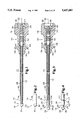
- FIG. 1 is a side view of a preferred embodiment of a knot tying instrument according to the present invention, in partial section.
- FIG. 2 is a side view of the distal end of the preferred embodiment of a knot tying instrument according to the present invention.
- FIG. 3 is a side view of the preferred embodiment of a knot tying instrument according to the present invention, in partial section, with a member thereof forced to its forward position and another member thereof forced to its rearward position.
- FIG. 4 is a side view of the distal end of the preferred embodiment of a knot tying instrument according to the present invention with a member thereof forced to its forward position and another member thereof forced to its rearward position.
- FIG. 5 is an exploded view in partial section of a second embodiment of a knot tying instrument according to the present invention, using a needle holder.
- FIG. 6 is a side view of the second embodiment of a knot tying instrument according to the present invention, in partial section.
- FIG. 7 is a side view in partial section of a third embodiment of a knot tying instrument according to the present invention, using a needle holder and with a member thereof forced to its rearward position.
- FIG. 8 is a side view in partial section of the third embodiment of a knot tying instrument according to the present invention, with a member thereof forced to its forward position.
- FIG. 9 is a side view of a fourth embodiment of a knot tying instrument according to the present invention, in partial section.
- FIG. 10 is a side view of the distal end of the fourth embodiment of a knot tying instrument according to the present invention.
- FIG. 11 is a side view in partial section of the fourth embodiment of a knot tying instrument according to the present invention, with a member thereof forced to its forward position.
- FIG. 12 is a side view of the distal end of the fourth embodiment of a knot tying instrument according the present invention, with a member thereof forced to its forward position.
- FIG. 13 is a side view of a fifth embodiment of a knot tying instrument according to the present invention, in partial section.
- FIG. 14 is a side view of the distal end of the fifth embodiment of a knot tying instrument according to the present invention.
- FIG. 15 is a side view in partial section of the fifth embodiment of the knot tying instrument according to the present invention, with a member thereof forced to its forward position.
- FIG. 16 is a side view of the distal end of the fifth embodiment of a knot tying instrument according to the present invention, with a member thereof forced to its forward position.
- FIGS. 17A-17L show a side view of the preferred embodiment of a knot tying instrument according to the present invention, and illustrate the preferred method for use thereof to tie a knot in a suture according to the present invention.
- FIGS. 18A-18E show a side view of the preferred embodiment of a knot tying instrument according to the present invention, and illustrate the preferred method for use thereof following the steps illustrated in FIGS. 17A-17L in tying a square knot.
- FIGS. 19A-19F show a side view of the preferred embodiment of a knot tying instrument according to the present invention, and illustrate the preferred method for use thereof following the steps illustrated in FIGS. 17A-17L in tying a surgeon's knot.
- FIGS. 20A-20Q show a side view of the preferred embodiment of a knot tying instrument according to the present invention, and illustrate the preferred method for use thereof in tying a running suture knot.
- a medical knot tying instrument 10 generally comprises an elongate, hollow first member 12, a gripping mechanism 14 and a holding mechanism 16.
- the first member has a distal end 18, a proximal end 20, and a longitudinal axis 22.
- the first member 12, at its proximal end 20, is attached to a handle 24.
- the gripping mechanism 14 provides for releasably gripping a first length of suture proximate the distal end 18 of the first member 12.
- the holding mechanism 16 provides for releasably holding a second length of suture proximate the distal end 18 of the first member 12 at a predetermined distance toward the first member's proximal end 20 from where the first length of suture is gripped by the gripping mechanism 14. It is to be recognized that the distance between where the first length of suture is gripped by the gripping mechanism 14 and where the second length of suture is held by the holding mechanism 16 is determined according to a combination of factors, including the type of suture being used, the lengths of suture to be tied, the procedure with which the knot tying instrument is to be used, as well as other factors and, accordingly, may vary from instrument to instrument without departing from the principles of the invention.
- the first member 12 has, at its distal end 18, an elongate collar 26 having a proximal face 27 and a distal face 29.
- the handle 24 is a figure of rotation centered on the longitudinal axis 22 of the first member 12 so as to provide facility in using the instrument 10, regardless of the rotational position thereof about the longitudinal axis 22.
- the gripping mechanism 14 comprises an elongate second member 28 slidably disposed within the first member 12, having a distal end and a proximal end.
- the head 30 Disposed at the distal end of the second member 28 is a head 30.
- the head 30 has a distal face 32 and proximal face 34, the distal face 32 being hemispherical so as to ease insertion of the instrument 10 through intracorporeal tissue.
- the second member 28 extends beyond the proximal end 20 of the first member 12, terminating in an operating mechanism 36.
- the handle 24 provides a recess 38 within which the operating mechanism 36 is disposed, though it is to be recognized that the operating mechanism 36 may extend outside the handle 24 without departing from the principles of the invention.
- the operating mechanism 36 comprises a push button 40 for selectively moving the second member 28 forward relative to the first member 12. So moving the second member 28 opens a first gap 42 between the head's proximal face 34 and the collar's distal face 29.
- the operating mechanism 36 further comprises a spring 44 which applies backward force on the second member 28. When the push button 40 is released, the spring 44 moves the second member 28 to a rearward position so as to bias the head's proximal face 34 against the collar's distal face 29, closing the first gap 42.
- the holding mechanism comprises an elongate, hollow third member 46 having a distal end 47 and a proximal end 49.
- the third member 46 is slidably disposed over the first member 12 between the handle 24 and the collar's proximal face 27.
- the third member at its proximal end 49, terminates in an operating mechanism 48.
- the operating mechanism 48 comprises a grip 50 for selectively moving the third member 46 rearward relative to the first member 12. So moving the third member 46 opens a second gap 54 between the collar's proximal face 27 and the third member's distal end 47.
- the operating mechanism 48 further comprises a spring 52 that applies forward force on the third member 46. When the grip 50 is released, the spring 52 moves the third member 46 to a forward position so as to bias the third member's distal end 47 against the collar's proximal face 27, closing the second gap 54.
- the grip 50 is provided with a pair of concave projections 56 extending laterally from opposite sides of the third member 46 so as to permit the user to place one finger in each of the respective concave projections 56 while cradling the handle 24 in the palm of the same hand or while operating the gripping mechanism 42 by selectively pushing and releasing the push button 40 using the thumb of the same hand.
- the user pushes or releases the push button 40 selectively to open or close the first gap 42.
- a suture may be received therein so that, when the first gap 42 substantially closes upon release of the push button 40, the suture is gripped between the head's proximal face 34 and the collar's distal face 29 due to the backward force applied by the spring 44.
- the user of the instrument 10 selectively pulls or releases the grip 50 to selectively open or close the second gap 54.
- suture may be placed therein so that, when the second gap 54 substantially closes upon release of the grip 50, the suture is held between the third member's distal end 47 and the collar's proximal face 27 due to the forward force applied by the spring 52.
- the second member 28 has a round cross-section
- the first member 12 and third member 46 each have annular cross-sections.
- the collar's proximal and distal faces 27 and 29 and the head's proximal face 34 preferably are annular, so that lengths of suture can be placed in the gaps 42 and 44 regardless of the rotational position of the instrument 10 about the longitudinal axis 22 of the first member 12.
- other cross-sectional shapes could be employed for the members and faces without departing from the principles of the invention.
- the head 30, the collar 26 and the distal end 47 of the third member 46 have uniform cross-sectional shapes where they meet so that, with the first gap 42 and the second gap 54 closed, the instrument 10 presents a smooth surface facilitating insertion of the instrument 10 into intracorporeal tissue.
- the head 30, the collar 26 and the third member's distal end 47 may have non-uniform cross-sectional shapes without departing from the principles of the invention.
- the maximum cross-sectional dimension of the instrument 10 should correspond to the internal diameter of the device, such as a trocar, through which the knot tying instrument 10 is introduced into the body cavity.
- the length of the first and second gaps 42 and 54 are user-selectable by selectively pushing or releasing the push button 40 and pulling or releasing the grip 50.
- the maximum size of the first and second gaps 42 and 54 is substantially determined by the difference between the compressed and uncompressed lengths of the respective springs 44 and 52 of the operating mechanisms 36 and 48. In experimental trials, a maximum gap size of 1/16 inch has been used with satisfactory results.
- FIGS. 5 and 6 a second embodiment of the knot tying instrument 10 in accordance with the present invention is shown, wherein the gripping mechanism is provided by a conventional needle holder 70.
- Needle holders are well-known in the art having, as shown in the Figures, an operating mechanism 72 and a clamping mechanism 74.
- the needle holder 70 is removably inserted through the hollow first member 12 of the knot tying instrument such that the operating mechanism 72 extends from the handle 24 while the clamping mechanism 74 extends from the distal end 18 of the first member 12 so as to grip a suture.
- the needle holder 70 is used in place of the second member 28 of the preferred embodiment and its associated structure, it is to be recognized that the second embodiment is otherwise substantially the same as the preferred embodiment in structure and operation.
- FIGS. 7 and 8 a third embodiment of the knot tying instrument 10 in accordance with the present invention is shown, wherein the gripping mechanism is provided by a conventional needle holder 70 having, as described above for the second embodiment, the operating mechanism 72 at the proximal end thereof and the clamping mechanism 74 at the distal end thereof.
- the holding mechanism 16 comprises an elongate, hollow member 200 slidably disposed within the first member 12, having a distal end and a proximal end.
- a sleeve 202 Disposed at the distal end of the member 200 is a sleeve 202 having a proximal face 204 and a distal face 206.
- the distal face 206 is rounded so as to ease insertion of the instrument 10 through intracorporeal tissue.
- the member 200 extends beyond the proximal end 20 of the first member 12, terminating in an operating mechanism 208.
- the operating mechanism 208 preferably comprises a push button 210 and a spring 212.
- the push button 210 includes a cylindrical aperture therethrough that is centered on the longitudinal axis 22 of the first member 10, through which the needle holder 70 is inserted. Pushing or releasing the push button 210 selectively opens or closes a gap 216 between the sleeve's proximal face 204 and the first member's distal end 18.
- the operation of the operating mechanism 208 is substantially the same as the operation of the operating mechanism 36 and can be understood with reference to the description thereof.
- the holding mechanism 16 comprises a V-shaped lateral notch 100 formed in the first member 12.
- the notch 100 is formed at a predetermined angle and is directed toward the distal end of the first member 12.
- the notch 100 has a predetermined depth and length so that a suture may be removably wedged therein.
- the gripping mechanism 14 is substantially the same as the preferred embodiment, except with respect to the distal end of the second member 28.
- the second member 28 has, at its distal end, a hook 102.
- the hook 102 extends a predetermined distance substantially perpendicularly to the longitudinal axis 22 of the first member 12. Although in FIGS. 9-12 the hook is shown to extend a distance beyond the first member 12, it is to be recognized that the hook 102 may be shorter or longer than the length shown without departing from the principles of the invention.
- the user pushes the push button 40 to move the hook 102 selectively away from the first member's distal end 18 so that a suture may be placed therebetween. When the push button 40 is released, the suture so placed is gripped between the hook 102 and the distal end 18 of the first member 12 by the backward force applied by the spring 44.
- the second member 28 has, at its distal end, a rounded tip 104 and has a lateral notch 106 spaced a distance D proximally from the tip 104.
- the lateral notch 106 has a predetermined length L, as shown in FIG. 13. The distance D and the length L of the lateral notch 106 are chosen so that, when the push button 40 is fully depressed, the lateral notch 106 is entirely outside the first member 12 and, when the push button is released, the lateral notch 106 is biased by the spring 44 entirely within the first member 12.
- the tip 104 preferably is rounded so as to facilitate insertion of the instrument 10 into intracorporeal tissue.
- the tip 104 may be used without departing from the principles of the invention. If the first member's distal end 18 is relatively thick, the distal end 18 preferably has a taper 108 so as to facilitate insertion of the instrument 10 into intracorporeal tissue.
- the operating mechanism 36 operates in substantially the same way as it operates in the preferred and third embodiments, except that the lateral notch 106 is moved outside the first member 12 in order to receive a suture and, when the button 40 is released, the suture is drawn partially into the first member 12.
- the members 12, 28 and 46 are made of materials suitable for surgical use, such as stainless steel and nylon. It is also preferred that the materials provide sufficient rigidity and resiliency so that the instrument 10 may be flexed selectively during use, yet transmit adequate force from the respective proximal end to the distal end so as to be inserted through abdominal tissues, particularly abdominal muscle, and subsequently return to the original shape.
- FIGS. 17A-17L through 20A-20Q The method of use of the instrument 10 is illustrated in FIGS. 17A-17L through 20A-20Q.
- intracorporeal abdominal tissue 120 is shown having an incision 122 to be closed. Extending from a first side 124 of the incision 122 is a first length 128 of suture. Extending from a second side 126 of the incision 122 is a second length 130 of suture.
- the instrument 10 is used to tie the first length 128 and the second length 130 by gripping the first length 128 using the gripping mechanism 14 and holding the second length 130 using the holding mechanism 16, as shown in FIGS. 17A-17D.
- the first length 128 is gripped in the first gap 42 between the head's proximal face 34 and the collar's distal face 29, and the second length 130 is held in the second gap 54 between the collar's proximal face 27 and the distal end 47 of the third member 46.
- a grasping instrument 132 is used to place the lengths 128 and 130 in the respective gaps 42 and 54
- the instrument 10 may be used without such grasping instrument 132, without departing from the principles of the invention.
- the instrument 10 may be used alone when the gaps 42 and 54 have annular cross-sections so as to receive a suture regardless of the rotational position of the instrument 10.
- the respective operating mechanisms 36 and 48 are used to open and close the first and second gaps 42 and 54 to receive and retain a suture.
- the instrument 10 With the lengths 128 and 130 so gripped and held, the instrument 10 is then rotated in one angular direction about the longitudinal axis 22 of the first member 12 so that the second length 130 forms a first loop 134 around the instrument 10, as shown in FIG. 17E.
- the second length 130 is then grasped by the grasping instrument 132 between the end thereof and where it is held by the holding mechanism 16, as shown in FIG. 17F.
- the second length 130 of suture is then released from the holding mechanism 16, in this case, by pulling on the grip 50, and the first length 128, gripped by the gripping mechanism 14, and the second length 130, grasped by the grasping instrument 132, are then moved in opposite directions so that the first length 128 passes through the first loop 134 formed in the second length 130, thereby forming a first throw 136 of a knot, as shown in FIGS. 17G-17H.
- the grasping instrument 132 must be positioned relative to the first length 128 so that the first length 128 will pass through the first loop 134 to form the first throw 136 as shown in FIGS. 17F-17H.
- a knot is completed by gripping the first length 128 in the gripping mechanism 14 and holding the second length 130 in the holding mechanism 16, as described above and as shown in FIGS. 17I-17K.
- the instrument 10 is then rotated about the longitudinal axis 22 of the first member 12 in an angular direction opposite the angular direction used in forming the first throw 136, so as to form a second loop 138, as shown in FIG. 17L.
- the user may selectively tie any of various knots, including a square knot or a surgeon's knot.
- the second length 130 is then grasped between the end thereof and the holding mechanism 16 using the grasping instrument 132, as shown in FIG. 18A.
- the second length 130 is then released from the holding mechanism 16, in this case by pulling on the grip 50 so as to open the second gap 54, as shown in FIG. 18B.
- the first length 128, gripped in the gripping mechanism 14, and the second length 130, grasped by the grasping instrument 132 are then pulled in opposite directions so that the first length 128 passes through the second loop 138 formed in the second length 130, so as to form a second throw 140, as shown in FIGS. 18C and 18D.
- the grasping instrument 132 must be positioned relative to the first length 128 so that the first length 128 will pass through the second loop 138.
- FIGS. 19A-19F the remaining steps necessary to form a surgeon's knot following the steps illustrated in FIGS. 17A-17L are shown.
- the instrument 10 is further rotated about the longitudinal axis 22 of the first member 12 in the same angular direction shown in FIG. 17N, so as to form a third loop 144 in the second length 130, as shown in FIG. 19A.
- a second throw 146 is formed by following steps illustrated in FIGS. 19B-19E which are substantially the same as, and will be understood from the description of, the steps described for FIGS. 18A-18D.
- FIG. 19F the directions of movement of the grasping instrument 132 and the knot tying instrument 10 are reversed from the directions of FIG. 19E to cinch the second throw 146 onto the first throw 136 so as to tighten a surgeon's knot 148.
- FIGS. 20A-20Q the steps used in tying a running knot are shown.
- the steps are substantially the same as, and will be understood from the description of, the steps used to tie the square knot as illustrated in FIGS. 17A-17L and 18A-18E, except for variations to account for attachment of a needle 146 to the end of the first length 128.
- the first length 128 is gripped by the gripping mechanism 14 at a predetermined distance from the needle 150 so that, in forming the throws of a surgeon's knot, the needle 150 will not pass through the loops formed in the second length 130 even though a portion of the first length 128 will pass through those loops.
- FIGS. 20H-20I and 20O-20P illustrate that the needle 150 does not pass through loops formed in the second length 130. As shown in FIG. 20Q, a loop 152 formed by the first length 128 extends from the resulting surgeon's knot 154.
- FIGS. 17A-17L, 18A-18E, 19A-19F and 20A-20Q may be repeated any number of times to form additional throws in tying one or more knots, as selected by the user.
Abstract
Description
Claims (46)
Priority Applications (1)
| Application Number | Priority Date | Filing Date | Title |
|---|---|---|---|
| US08/094,771 US5437682A (en) | 1993-07-20 | 1993-07-20 | Medical knot tying instrument and method for use thereof |
Applications Claiming Priority (1)
| Application Number | Priority Date | Filing Date | Title |
|---|---|---|---|
| US08/094,771 US5437682A (en) | 1993-07-20 | 1993-07-20 | Medical knot tying instrument and method for use thereof |
Publications (1)
| Publication Number | Publication Date |
|---|---|
| US5437682A true US5437682A (en) | 1995-08-01 |
Family
ID=22247069
Family Applications (1)
| Application Number | Title | Priority Date | Filing Date |
|---|---|---|---|
| US08/094,771 Expired - Lifetime US5437682A (en) | 1993-07-20 | 1993-07-20 | Medical knot tying instrument and method for use thereof |
Country Status (1)
| Country | Link |
|---|---|
| US (1) | US5437682A (en) |
Cited By (21)
| Publication number | Priority date | Publication date | Assignee | Title |
|---|---|---|---|---|
| US5746753A (en) * | 1996-05-13 | 1998-05-05 | Boston Scientific Corporation | Needle grasping apparatus |
| US6152934A (en) * | 1999-06-14 | 2000-11-28 | Ethicon Endo-Surgery, Inc. | Surgical knot tying instrument |
| US6245077B1 (en) * | 2000-01-21 | 2001-06-12 | Exmoor Plastics Ltd. | Universal myringotomy tube/aural grommet inserter and methods |
| US20010053916A1 (en) * | 2000-06-05 | 2001-12-20 | Rioux Robert F. | Methods and devices for the treatment of urinary incontinence |
| US6550177B1 (en) * | 2001-12-18 | 2003-04-22 | John A. Epple, Jr. | Hackle grabber |
| US6676673B2 (en) * | 2001-05-25 | 2004-01-13 | Yu-Chung Chang | Surgical needle |
| US6702339B1 (en) * | 2002-10-11 | 2004-03-09 | Khachik Geozalian | Fishing hook knot tightening device |
| US6716224B2 (en) | 2000-08-28 | 2004-04-06 | Linvatec Corporation | Intracorporeal knot tier |
| US20060178681A1 (en) * | 1998-03-20 | 2006-08-10 | Boston Scientific Scimed, Inc. | Endoscopic suture systems |
| US20060195140A1 (en) * | 2004-03-26 | 2006-08-31 | Olympus Corporation | Surgical gripper |
| JP2006230958A (en) * | 2005-02-28 | 2006-09-07 | Olympus Corp | Surgical operation instrument |
| US20080021499A1 (en) * | 2004-05-14 | 2008-01-24 | Olympus Corporation | Surgical instrument |
| US20080061556A1 (en) * | 2006-09-12 | 2008-03-13 | Sergio Bernal | Knot Tying Device |
| US20080139877A1 (en) * | 2001-03-09 | 2008-06-12 | Boston Scientific Scimed, Inc. | Systems, methods and devices relating to delivery of medical implants |
| US20090318938A1 (en) * | 2008-06-18 | 2009-12-24 | Tyco Healthcare Group Lp | Spring-Type Suture Securing Device |
| US20110046643A1 (en) * | 2009-08-18 | 2011-02-24 | Terumo Kabushiki Kaisha | Suturing and ligating method |
| US20110190794A1 (en) * | 2010-01-29 | 2011-08-04 | Richard Wolf Gmbh | Medical needle holder |
| US20120221045A1 (en) * | 2011-02-25 | 2012-08-30 | Yu-Chung Chang | Needle unit |
| EP2837336A3 (en) * | 2004-05-11 | 2015-06-03 | Olympus Corporation | Surgical operation instrument with passively rotatable clamping portion |
| US9149261B2 (en) | 2001-03-09 | 2015-10-06 | Boston Scientific Scimed, Inc. | Systems, methods and devices relating to delivery of medical implants |
| WO2021158922A1 (en) * | 2020-02-07 | 2021-08-12 | Children's Medical Center Corporation | Intracorporeal suture tying |
Citations (25)
| Publication number | Priority date | Publication date | Assignee | Title |
|---|---|---|---|---|
| DE46014C (en) * | F. SCHULTZE in Berlin SW., Grofsbeerenstr. 64 a | Rain countercurrent condenser | ||
| US532306A (en) * | 1895-01-08 | Surgical-needle holder | ||
| US984756A (en) * | 1909-09-08 | 1911-02-21 | Paul Frisch | Surgical forceps. |
| US1539221A (en) * | 1923-10-30 | 1925-05-26 | Tennant John William | Welder's rod holder |
| US2363334A (en) * | 1943-03-02 | 1944-11-21 | William O Jones | Surgical needle holder |
| US2455833A (en) * | 1946-09-09 | 1948-12-07 | Trombetta Louis | Clamping and knot tying instrument |
| US3396998A (en) * | 1967-03-29 | 1968-08-13 | Wright A. Scoville | Fishhook holder |
| DE1810806A1 (en) * | 1968-11-25 | 1970-06-11 | Dr Med Gerhard Metz | Surgical needle holder with increasing translation and hand-friendly grip technique |
| US3625556A (en) * | 1969-10-09 | 1971-12-07 | Henry K Stromberg | Looper |
| US3828791A (en) * | 1973-03-21 | 1974-08-13 | M Santos | Surgical instruments |
| US3871379A (en) * | 1971-08-26 | 1975-03-18 | Henry C N Clarke | Laparoscopy instruments and method for suturing and ligation |
| US4617933A (en) * | 1980-02-19 | 1986-10-21 | Hasson Harrith M | Laparoscope cannula with improved suture receiving means |
| US4641652A (en) * | 1984-04-12 | 1987-02-10 | Richard Wolf Gmbh | Applicator for tying sewing threads |
| DE3808877A1 (en) * | 1988-03-17 | 1989-09-28 | Hermann Dausch | Microsurgical instrument |
| DE3812165A1 (en) * | 1988-04-12 | 1989-10-26 | Lemar Wahab Dr Hamidi | Insertion forceps for a tracheal tube |
| US5100418A (en) * | 1987-05-14 | 1992-03-31 | Inbae Yoon | Suture tie device system and applicator therefor |
| US5129912A (en) * | 1991-01-07 | 1992-07-14 | Laparomed Corporation | Device and method for applying suture |
| US5133724A (en) * | 1991-04-04 | 1992-07-28 | Pilling Co. | Abdominal aortic clamp |
| US5152769A (en) * | 1991-11-04 | 1992-10-06 | Will Baber | Apparatus for laparoscopic suturing with improved suture needle |
| US5171257A (en) * | 1991-04-29 | 1992-12-15 | Ferzli George S | Laparoscopic instrument |
| US5234443A (en) * | 1991-07-26 | 1993-08-10 | The Regents Of The University Of California | Endoscopic knot tying apparatus and methods |
| US5250054A (en) * | 1992-05-01 | 1993-10-05 | Li Medical Technologies, Inc. | Intracorporeal knot tying apparatus and method |
| US5261917A (en) * | 1992-02-19 | 1993-11-16 | Hasson Harrith M | Suture tying forceps with a plurality of suture holders and method of tying a suture |
| US5281237A (en) * | 1992-09-25 | 1994-01-25 | Gimpelson Richard J | Surgical stitching device and method of use |
| US5300082A (en) * | 1992-01-08 | 1994-04-05 | Sharpe Endosurgical Corporation | Endoneedle holder surgical instrument |
-
1993
- 1993-07-20 US US08/094,771 patent/US5437682A/en not_active Expired - Lifetime
Patent Citations (27)
| Publication number | Priority date | Publication date | Assignee | Title |
|---|---|---|---|---|
| DE46014C (en) * | F. SCHULTZE in Berlin SW., Grofsbeerenstr. 64 a | Rain countercurrent condenser | ||
| US532306A (en) * | 1895-01-08 | Surgical-needle holder | ||
| US984756A (en) * | 1909-09-08 | 1911-02-21 | Paul Frisch | Surgical forceps. |
| US1539221A (en) * | 1923-10-30 | 1925-05-26 | Tennant John William | Welder's rod holder |
| US2363334A (en) * | 1943-03-02 | 1944-11-21 | William O Jones | Surgical needle holder |
| US2455833A (en) * | 1946-09-09 | 1948-12-07 | Trombetta Louis | Clamping and knot tying instrument |
| US3396998A (en) * | 1967-03-29 | 1968-08-13 | Wright A. Scoville | Fishhook holder |
| DE1810806A1 (en) * | 1968-11-25 | 1970-06-11 | Dr Med Gerhard Metz | Surgical needle holder with increasing translation and hand-friendly grip technique |
| US3625556A (en) * | 1969-10-09 | 1971-12-07 | Henry K Stromberg | Looper |
| US3871379A (en) * | 1971-08-26 | 1975-03-18 | Henry C N Clarke | Laparoscopy instruments and method for suturing and ligation |
| US3828791A (en) * | 1973-03-21 | 1974-08-13 | M Santos | Surgical instruments |
| US4617933A (en) * | 1980-02-19 | 1986-10-21 | Hasson Harrith M | Laparoscope cannula with improved suture receiving means |
| US4641652A (en) * | 1984-04-12 | 1987-02-10 | Richard Wolf Gmbh | Applicator for tying sewing threads |
| US5100418A (en) * | 1987-05-14 | 1992-03-31 | Inbae Yoon | Suture tie device system and applicator therefor |
| DE3808877A1 (en) * | 1988-03-17 | 1989-09-28 | Hermann Dausch | Microsurgical instrument |
| DE3812165A1 (en) * | 1988-04-12 | 1989-10-26 | Lemar Wahab Dr Hamidi | Insertion forceps for a tracheal tube |
| US5129912B1 (en) * | 1991-01-07 | 1999-11-09 | Urohealth Systems Inc | Device and method for applying suture |
| US5129912A (en) * | 1991-01-07 | 1992-07-14 | Laparomed Corporation | Device and method for applying suture |
| US5129912B2 (en) * | 1991-01-07 | 2000-01-11 | Urohealth Systems Inc | Device and method for applying suture |
| US5133724A (en) * | 1991-04-04 | 1992-07-28 | Pilling Co. | Abdominal aortic clamp |
| US5171257A (en) * | 1991-04-29 | 1992-12-15 | Ferzli George S | Laparoscopic instrument |
| US5234443A (en) * | 1991-07-26 | 1993-08-10 | The Regents Of The University Of California | Endoscopic knot tying apparatus and methods |
| US5152769A (en) * | 1991-11-04 | 1992-10-06 | Will Baber | Apparatus for laparoscopic suturing with improved suture needle |
| US5300082A (en) * | 1992-01-08 | 1994-04-05 | Sharpe Endosurgical Corporation | Endoneedle holder surgical instrument |
| US5261917A (en) * | 1992-02-19 | 1993-11-16 | Hasson Harrith M | Suture tying forceps with a plurality of suture holders and method of tying a suture |
| US5250054A (en) * | 1992-05-01 | 1993-10-05 | Li Medical Technologies, Inc. | Intracorporeal knot tying apparatus and method |
| US5281237A (en) * | 1992-09-25 | 1994-01-25 | Gimpelson Richard J | Surgical stitching device and method of use |
Non-Patent Citations (2)
| Title |
|---|
| Ethicon, Endoscopic Knot Tying Manual, 1991, pp. 24 25. * |
| Ethicon, Endoscopic Knot Tying Manual, 1991, pp. 24-25. |
Cited By (36)
| Publication number | Priority date | Publication date | Assignee | Title |
|---|---|---|---|---|
| US6102920A (en) * | 1996-05-13 | 2000-08-15 | Boston Scientific Corporation | Needle grasping apparatus |
| US5746753A (en) * | 1996-05-13 | 1998-05-05 | Boston Scientific Corporation | Needle grasping apparatus |
| US20060178681A1 (en) * | 1998-03-20 | 2006-08-10 | Boston Scientific Scimed, Inc. | Endoscopic suture systems |
| US8382774B2 (en) * | 1998-03-20 | 2013-02-26 | Boston Scientific Scimed, Inc. | Endoscopic suture systems |
| US9585652B2 (en) | 1998-03-20 | 2017-03-07 | Boston Scientific Scimed, Inc. | Endoscopic suture systems |
| US9095334B2 (en) | 1998-03-20 | 2015-08-04 | Boston Scientific Scimed, Inc. | Endoscopic suture systems |
| US6152934A (en) * | 1999-06-14 | 2000-11-28 | Ethicon Endo-Surgery, Inc. | Surgical knot tying instrument |
| US6245077B1 (en) * | 2000-01-21 | 2001-06-12 | Exmoor Plastics Ltd. | Universal myringotomy tube/aural grommet inserter and methods |
| US20050085831A1 (en) * | 2000-06-05 | 2005-04-21 | Scimed Life Systems, Inc. | Methods and devices for the treatment of urinary incontinence |
| US8858575B2 (en) | 2000-06-05 | 2014-10-14 | Boston Scientific Scimed, Inc. | Methods and devices for the treatment of urinary incontinence |
| US20010053916A1 (en) * | 2000-06-05 | 2001-12-20 | Rioux Robert F. | Methods and devices for the treatment of urinary incontinence |
| US7527633B2 (en) * | 2000-06-05 | 2009-05-05 | Boston Scientific Scimed Inc. | Methods and devices for the treatment of urinary incontinence |
| US20110213388A1 (en) * | 2000-06-05 | 2011-09-01 | Boston Scientific Scimed, Inc. | Methods and devices for the treatment of urinary incontinence |
| US7927342B2 (en) | 2000-06-05 | 2011-04-19 | Boston Scientific Scimed, Inc. | Methods and devices for the treatment of urinary incontinence |
| US6716224B2 (en) | 2000-08-28 | 2004-04-06 | Linvatec Corporation | Intracorporeal knot tier |
| US8602965B2 (en) | 2001-03-09 | 2013-12-10 | Boston Scientific Scimed, Inc. | System, methods and devices relating to delivery of medical implants |
| US10117733B2 (en) | 2001-03-09 | 2018-11-06 | Boston Scientific Scimed, Inc. | Systems, methods and devices relating to delivery of medical implants |
| US9149261B2 (en) | 2001-03-09 | 2015-10-06 | Boston Scientific Scimed, Inc. | Systems, methods and devices relating to delivery of medical implants |
| US20080139877A1 (en) * | 2001-03-09 | 2008-06-12 | Boston Scientific Scimed, Inc. | Systems, methods and devices relating to delivery of medical implants |
| US6676673B2 (en) * | 2001-05-25 | 2004-01-13 | Yu-Chung Chang | Surgical needle |
| US6550177B1 (en) * | 2001-12-18 | 2003-04-22 | John A. Epple, Jr. | Hackle grabber |
| US6702339B1 (en) * | 2002-10-11 | 2004-03-09 | Khachik Geozalian | Fishing hook knot tightening device |
| US20060195140A1 (en) * | 2004-03-26 | 2006-08-31 | Olympus Corporation | Surgical gripper |
| US7854749B2 (en) * | 2004-03-26 | 2010-12-21 | Olympus Corporation | Surgical gripper |
| EP2837336A3 (en) * | 2004-05-11 | 2015-06-03 | Olympus Corporation | Surgical operation instrument with passively rotatable clamping portion |
| US7972345B2 (en) * | 2004-05-14 | 2011-07-05 | Olympus Corporation | Surgical instrument |
| US20080021499A1 (en) * | 2004-05-14 | 2008-01-24 | Olympus Corporation | Surgical instrument |
| JP2006230958A (en) * | 2005-02-28 | 2006-09-07 | Olympus Corp | Surgical operation instrument |
| US20080061556A1 (en) * | 2006-09-12 | 2008-03-13 | Sergio Bernal | Knot Tying Device |
| US8579921B2 (en) * | 2008-06-18 | 2013-11-12 | Covidien Lp | Spring-type suture securing device |
| US20090318938A1 (en) * | 2008-06-18 | 2009-12-24 | Tyco Healthcare Group Lp | Spring-Type Suture Securing Device |
| US9271718B2 (en) * | 2009-08-18 | 2016-03-01 | Karl Storz Gmbh & Co. Kg | Suturing and ligating method |
| US20110046643A1 (en) * | 2009-08-18 | 2011-02-24 | Terumo Kabushiki Kaisha | Suturing and ligating method |
| US20110190794A1 (en) * | 2010-01-29 | 2011-08-04 | Richard Wolf Gmbh | Medical needle holder |
| US20120221045A1 (en) * | 2011-02-25 | 2012-08-30 | Yu-Chung Chang | Needle unit |
| WO2021158922A1 (en) * | 2020-02-07 | 2021-08-12 | Children's Medical Center Corporation | Intracorporeal suture tying |
Similar Documents
| Publication | Publication Date | Title |
|---|---|---|
| US5437682A (en) | Medical knot tying instrument and method for use thereof | |
| US5320629A (en) | Device and method for applying suture | |
| US5129912A (en) | Device and method for applying suture | |
| US5649939A (en) | Laparoscopic suture introducer | |
| US9642614B1 (en) | Apparatus and method for minimally invasive suturing | |
| US5234444A (en) | Christoudias knot--transfer method and instrument | |
| US5336230A (en) | Endoscopic suture tying method | |
| US5810845A (en) | Ligating instrument with multiple loop ligature supply and methods therefor | |
| US5211650A (en) | Dual function suturing device and method | |
| US5312423A (en) | Apparatus and method for laparaoscopic ligation | |
| US5676675A (en) | Laparo-suture needle and method for use thereof | |
| US6143005A (en) | Suturing instrument with rotatably mounted offset needle holder and method of using the same | |
| US5217471A (en) | Endoscopic suture knotting instrument | |
| US5899911A (en) | Method of using needle-point suture passer to retract and reinforce ligaments | |
| US5192287A (en) | Suture knot tying device | |
| US5281237A (en) | Surgical stitching device and method of use | |
| US5728112A (en) | Combined tissue clamping and suturing instrument | |
| US5397326A (en) | Knot pusher for videoendoscopic surgery | |
| US5827299A (en) | Insertable suture passing grasping probe and methodology for using same | |
| US5507758A (en) | Insertable suture grasping probe guide, and methodology for using same | |
| US6171316B1 (en) | Endoscopic surgical instrument for rotational manipulation | |
| US5571119A (en) | Retractable suture needle with self-contained driver | |
| US5181919A (en) | Suture ligating device for use with an endoscope | |
| US5772672A (en) | Endoscopic suture passer | |
| US20160106416A1 (en) | Medical implement for manipulating sutures particularly useful in arthroscopic surgery |
Legal Events
| Date | Code | Title | Description |
|---|---|---|---|
| AS | Assignment |
Owner name: IDEAS FOR MEDICINE, INC., FLORIDA Free format text: ASSIGNMENT OF ASSIGNORS INTEREST;ASSIGNORS:BENHAM, THOMAS H.;BUHLER, MICHAEL;REEL/FRAME:006708/0045 Effective date: 19930716 |
|
| STPP | Information on status: patent application and granting procedure in general |
Free format text: APPLICATION UNDERGOING PREEXAM PROCESSING |
|
| AS | Assignment |
Owner name: CRYOLIFE ACQUISITION CORPORATION, A FLORIDA CORPO Free format text: MERGER;ASSIGNOR:IDEAS FOR MEDICINE, INC., A FLORIDA CORPORATION;REEL/FRAME:008650/0688 Effective date: 19970303 |
|
| AS | Assignment |
Owner name: CRYOLIFE ACQUISITION CORPORATION, FLORIDA Free format text: CONFIRMATORY ASSIGNMENT;ASSIGNOR:IDEAS FOR MEDICINE, INC.;REEL/FRAME:008967/0431 Effective date: 19970305 |
|
| AS | Assignment |
Owner name: HORIZON MEDICAL PRODUCTS, INC., GEORGIA Free format text: ASSIGNMENT OF ASSIGNORS INTEREST;ASSIGNOR:IDEAS FOR MEDICINE, INC.;REEL/FRAME:009605/0821 Effective date: 19980930 |
|
| FPAY | Fee payment |
Year of fee payment: 4 |
|
| AS | Assignment |
Owner name: NATIONSCREDIT COMMERCIAL CORPORATION, CONNECTICUT Free format text: ASSIGNMENT OF ASSIGNORS INTEREST;ASSIGNOR:HORIZON MEDICAL PRODUCTS, INC.;REEL/FRAME:009711/0133 Effective date: 19980930 |
|
| AS | Assignment |
Owner name: HORIZON MEDICAL PRODUCTS, INC., GEORGIA Free format text: RELEASE OF SECURITY INTEREST;ASSIGNOR:BANK OF AMERICA N.A., F/K/A NATIONSCREDIT COMMERCIAL CORPORATION;REEL/FRAME:011712/0235 Effective date: 20010330 |
|
| AS | Assignment |
Owner name: VASCUTECH ACQUISITION LLC, MASSACHUSETTS Free format text: ASSIGNMENT OF ASSIGNORS INTEREST;ASSIGNOR:HORIZON MEDICAL PRODUCTS, INC.;REEL/FRAME:011712/0243 Effective date: 20010330 |
|
| FEPP | Fee payment procedure |
Free format text: PAYER NUMBER DE-ASSIGNED (ORIGINAL EVENT CODE: RMPN); ENTITY STATUS OF PATENT OWNER: SMALL ENTITY Free format text: PAYOR NUMBER ASSIGNED (ORIGINAL EVENT CODE: ASPN); ENTITY STATUS OF PATENT OWNER: SMALL ENTITY |
|
| FPAY | Fee payment |
Year of fee payment: 8 |
|
| FEPP | Fee payment procedure |
Free format text: PAYER NUMBER DE-ASSIGNED (ORIGINAL EVENT CODE: RMPN); ENTITY STATUS OF PATENT OWNER: SMALL ENTITY Free format text: PAYOR NUMBER ASSIGNED (ORIGINAL EVENT CODE: ASPN); ENTITY STATUS OF PATENT OWNER: SMALL ENTITY |
|
| FPAY | Fee payment |
Year of fee payment: 12 |