US5446474A - Redeployable furlable rib reflector - Google Patents
Redeployable furlable rib reflector Download PDFInfo
- Publication number
- US5446474A US5446474A US08/184,243 US18424394A US5446474A US 5446474 A US5446474 A US 5446474A US 18424394 A US18424394 A US 18424394A US 5446474 A US5446474 A US 5446474A
- Authority
- US
- United States
- Prior art keywords
- rib
- assembly
- reflector
- furling
- bottom plate
- Prior art date
- Legal status (The legal status is an assumption and is not a legal conclusion. Google has not performed a legal analysis and makes no representation as to the accuracy of the status listed.)
- Expired - Fee Related
Links
Images


Classifications
-
- H—ELECTRICITY
- H01—ELECTRIC ELEMENTS
- H01Q—ANTENNAS, i.e. RADIO AERIALS
- H01Q15/00—Devices for reflection, refraction, diffraction or polarisation of waves radiated from an antenna, e.g. quasi-optical devices
- H01Q15/14—Reflecting surfaces; Equivalent structures
- H01Q15/16—Reflecting surfaces; Equivalent structures curved in two dimensions, e.g. paraboloidal
- H01Q15/161—Collapsible reflectors
Definitions
- the present invention relates generally to redeployable dish reflectors and, more particularly, to low cost furlable rib parabolic dish reflectors for use with radio frequency antenna assemblies. Redeployable reflectors of the kind described herein are advantageously used in conjunction with mobile and portable ground station communication applications.
- Reflectors for use in conjunction with radio frequency antenna assemblies for ground station communication applications are well know in the art.
- such reflectors consist of a parabolic dish-shaped reflector surface that is stretched across and attached to a plurality of ribs which are individually pivotally connected to and radially extended from a central support hub.
- the redeployable reflector be constructed from commercially available components in a very simple and low cost manner thereby avoiding the need for expensive specially fabricated and high precision parts of the prior art, such as, for example, precision spherical bearings and pivot assemblies used for pivotally attaching the ribs to the central support hub.
- the overall design, installation and break down of the reflector be simple such that fabrication and adjustment can be carried out using only common hand tools and basic machine tools. It would be of further advantage where only low or minimally skilled labor is needed for deployment and redeployment of the reflector.
- the design for the reflector permit construction of dish diameter sized for a particular application such that any greater of fewer number of supporting radial ribs can be added to or removed from the central hub in order to fine tune the accuracy of the reflector surface configuration for good performance within a particular range or band width of signal frequencies.
- a preferred embodiment of the present invention is directed to a redeployable, furlable rib reflector which is furlable and unfurlable between a first stowed position and a second deployed position.
- the reflector comprises a generally spool-shaped hub assembly adapted to receive an antenna feed horn assembly mounted thereon and which includes a top plate member and a bottom plate member spaced therefrom.
- a plurality of modular rib assemblies are provided, spaced about the periphery of the hub assembly.
- Each modular rib assembly includes a channel section base member attachable between the top and bottom plate members and a generally, upwardly (parabolically shaped) curved rib member.
- the rib members are constructed of a suitably stiff material such that when the reflector is in the deployed position, the rib members support a preformed lightweight flexible metalized mesh material stretched there across and attached thereto to form a dish-shaped reflective surface.
- the rib members are elastic or furlable upon application of a bending force to permit circumferential wrapping or furling about the hub periphery during stowage operation.
- the modular rib assemblies further include simple a door hinge for pivotally attaching the inward end of each rib member to its respective channel section base member.
- the hinge axis of each hinge is preferably obliquely oriented with respect to the vertical axis of the adjoining channel section base member to facilitate compact stowage of the reflector, i.e., the parabolically curved upward ribs are angled slightly upward at their inner hub ends in order to achieve a lower stack height when furled about the hub.
- the invention further includes manually actuable rib furling means comprising an annular ring assembly which is rotatably attached to the hub for furling and unfurling the rib members about the hub between the stowed and deployed positions of the reflector.
- the annular ring assembly is provided with a number of rib furling elements in the form of candle-like members which extend therefrom and which are interposed between selected adjacent pairs of ribs.
- the annular ring assembly also includes a handle, and preferably two opposed handles, disposed along its circumference which can be manually actuated by a user for rotating the annular ring assembly in order to bring the rib furling elements into contact with the ribs.
- a simple bearing keeper assembly is also provided for rotatably mounting the annular ring assembly to the hub.
- the bearing keeper includes a plurality of hard plastic button-like spacers affixed to the bearing side of the annular ring assembly for riding on top of the adjacent mating surface of the hub (i.e., the bottom plate member of the hub) and a plurality of button-like retainers fixed to and extended from the annular ring assembly and positioned to engagingly retain the peripheral edge of the bottom plate member of the hub.
- a single TEFLON® TEFLON is a registered trademark of DuPont Corporation
- ring bearing like material or coating is providing in place of the hard plastic button-like spacers.
- each modular rib assembly forms a peripheral wall portion of the hub, thereby simplifying the hub design and serving a dual function of: (1) stiffening the hub; and (2) providing a point of attachment for the rib members to the hub.
- Another advantage of the present invention is that all components for the reflector are either readily commercially available or can be easily fabricated using basic machine tools.
- Still another advantage of the present invention is that the reflector can be assembled and adjusted using only simple hand tools. For example, since the pivotal attachment of the rib members to the hub make use simple commercially available door hinges, accurization or adjustment of the pivot assembly may be carried out using only a ball peen hammer.
- FIG. 1 is a perspective view of one embodiment of the redeployable furlable rib reflector shown in the deployed position.
- FIG. 2 is an enlarged fragmentary perspective view of the central hub assembly region of FIG. 1.
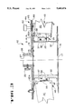
- FIG. 3 is a side elevation view in cross section taken along the line and in the direction of arrows 3--3 of FIG. 2.
- FIG. 4 is an exploded perspective view of the central hub assembly region shown in FIG. 2.
- FIG. 5 is an exploded perspective view of a modular rib assembly which is attachable to the hub assembly.
- FIG. 6A is a close up perspective view of the modular rib assembly of FIG. 5 shown with the annular ring assembly positioned thereover and also showing a rib furling element disposed contacting the rib member.
- FIG. 6A also illustrates one embodiment for the bearing keeper assembly which includes a plurality of hard plastic button spacers spaced apart along the circumference of the annular ring assembly for providing a slidable bearing surface between the annular ring assembly and the bottom plate member of the hub assembly.
- FIG. 6B is a close up perspective view similar to FIG. 6A showing an alternate embodiment for the bearing keeper assembly which includes a thin hard plastic ring member.
- FIGS. 7-9 are a series of diagrammatic views which illustrate how the attachable/detachable modular rib assemblies can be varied in number according to the size and performance requirement for a particular reflector application.
- FIG. 10 is a perspective view which illustrates how the reflector of the present invention can be manually stowed and/or deployed by a single person.
- FIG. 11 is a perspective view similar to FIG. 10 showing the reflector in the stowed position.
- FIG. 11A is an enlarged fragmentary perspective view of the region 11A of FIG. 10 showing the detail of a spring loaded locking pin device for locking the rotatable annular ring assembly to the bottom plate of the hub assembly.
- FIG. 12 is a perspective view showing a container for a fully stowed reflector for portable or mobile applications.
- a redeployable furlable rib reflector constructed in accordance with one embodiment of the present invention is indicated generally by reference numeral 10 in FIG. 1.
- the reflector 10 in FIG. 1 is shown in the deployed position and includes a central hub assembly 12 on which an antenna feed assembly 18 is mounted and which, in turn, is mountable to a fixed support (not shown) by a standoff assembly 20.
- the reflector 10 further includes a plurality of radially extendable modular rib assemblies 22 spaced about and pivotally attached to the hub assembly 12. In the deployed position shown, the modular rib assemblies form a parabolic dish shape.
- a light weight metalized mesh 24 is stretched across and secured to the modular rib assemblies 22 to form the dish-shaped reflective surface.
- the hub assembly 12 is generally spool shaped and comprises a pair of spaced apart generally circular plate members including a bottom plate member 14 and a top plate member 16, both preferably formed from aluminum or light-metal stock having suitable thickness to meet stiffness requirements.
- the bottom and top plate members 14 and 16 are each provided with a central axial bore hole 15 and 17, respectively, sized for removably mounting a support (not shown) for an antenna feed.
- a collar 26 is secured to the underside of bottom plate member 14 with its center through bore 27 axially aligned with the bore hole 15 and includes a threaded lock knob 28 for fixing an antenna feed support tube (not shown) within the hub assembly 12 (i.e., within holes 15 and 17 of bottom and top plate members 14 and 16, respectively, and within through bore 27 of collar 26).
- the bottom and top plate members 14 and 16 are held in a spaced relationship by a plurality of channel members 30, C-shaped in cross section, which are evenly spaced about the periphery of the hub assembly 12.
- each channel member 30 serves a dual function, since in addition to forming a side wall portion of the hub assembly, they also serve as the base or anchor portion for each of the modular rib assemblies 22.
- the individual channel members 30 are preferably fabricated from a single aluminum or light metal extrusion which is sectioned off along its length at regular intervals.
- the channel members 30 are secured in place by rivet fasteners 31 directed through coaligned holes 15a and 17a provided to the periphery of each of the bottom and top plate members 14 and 16, respectively.
- An advantageous feature of the present invention is that the overall design of the reflector itself does not change for different reflector sizes. Only different sized hardware components are required to build a reflector of a larger or smaller diameter, i.e. rib members, channel members, top and bottom plate members, etc.
- each of the modular rib assemblies 22 further include (in addition to the above mention channel member 30) a rib member 32 having an inner rib end 32a and an outer rib end 32b and a hinge assembly 34 for pivotally connecting the inner rib end 32a to the channel member 30.
- Each rib member 32 is upwardly curved along its radial length from inner end 32a to outward end 32b in conformity with the desired parabolic dish shape of the reflector surface.
- the rib members 32 are preferably parabolic (i.e. a segment of a circle) in cross section. The radius of this cross section is selected such that the stresses with the rib member are within the allowable limit of the strength of the material.
- the rib members 32 are preferably formed from commercially available, high strength aluminum sheet stock of constant gauge thickness, such as, for example, 7075 T6 aluminum with a 0.024 inch thickness.
- the preferred means or method for attaching the metalized mesh 27 to the rib members 32 is by sewing, using a suitable filament material such as, for example, dacron yarn directed through a plurality of spaced threading holes 33 provided along the length of the rib member 32 as shown in FIGS. 5-6.
- the metalized mesh may be glued directly to the ribs using a suitable adhesive.
- the hinge assembly 34 preferably includes a simple door hinge 35 which may be purchased from a local hardware store.
- the hinge 35 is pinned along a first side edge by bolt fasteners 36 to an L-bracket or angle 37 which, in turn, is pinned or riveted to the channel member 30 by pins 37a.
- the opposite side edge of the hinge 35 is connected by pins 39 to a fitting 38 which, in turn, is connected by pins 40 to the inner end 32a of rib member 32.
- the fitting 38 is preferably formed as a length of stainless steel sheet stock that has been bent at its opposing ends to conform to the parabolic curvature of the rib member inner end 32a.
- the preferred rib furling means comprise an annular ring assembly 44 which is rotatably mounted to the underside of the bottom plate member 14.
- the means for rotatably mounting the ring assembly 44 to the hub assembly is discussed in more detail below with reference to FIGS. 6A-6B.
- the annular ring assembly 44 preferably consists of two flat aluminum ring members 45, 46, sandwiched together and spaced apart by a plurality of spacers 47, and on which a plurality of upstanding rib furling elements 48 in the form of candle-like assemblies are secured. While in an alternate embodiment, a single ring member will suffice and function the same as the dual ring member construction shown and described herein, it is found that the two ring member construction provides superior rigidity for handling the loads experienced at the junctures with the individual rib furling elements 48.
- the rib furling elements 48 are preferably removably mounted spaced about the periphery of the annular ring assembly 44 and are disposed projecting upwardly (i.e., in the direction from the bottom plate member 14 to the top plate member 16) between selected adjacent pairs of rib members 32.
- the preferred number and spacing of the rib furling elements 48 is dependent on the size of the reflector 10 and the number of modular rib assemblies 22 to the included therewith. For best results, the rib furling elements should be interposed between every two or three rib members 32.
- the rib furling elements 48 consist of an inner steel rod 49 fixedly mounted to the ring assembly and an outer and rotatably mounted aluminum sleeve 50.
- a suitable bearing surface is interposed between the rod 49 and sleeve 50, such as, for example, a thin shrink fit plastic tubing (not shown) provided to the outer surface of the rod 49.
- the rib furling elements 48 may consist of a simple rod member having a slick outer surface to permit low friction slidable contact with the rib members 32 as they are brought into contact thereagainst upon rotation of the ring assembly during stowage or deployment operations of the reflector 10.
- the annular ring assembly 44 is also provided with at least one and preferably two handles 52 disposed mounted along the back side thereof to facilitate manually rotation of the ring assembly 44 in order to furl unfurl the rib members 32 about the hub assembly 12.
- the annular ring assembly further includes a spring loaded lock ring 53 to lock the rotatably annular ring assembly 44 in place with respect to the hub assembly 12 in both the stowed and deployed positions of the reflector 10.
- the dimensions for the hub diameter and rib length and number of rib furling elements are selected such that the reflector is fully deployed or fully stowed upon one revolution of the annular ring assembly.
- the two hole drillings in the angle 37 which receive the bolt fasteners 36 are offset such that the pivot axis of the hinge is obliquely oriented with respect to the central vertical axis of the hub assembly by an angle ⁇ .
- the angle ⁇ is selected as the tangent to the parabola at the location of the hinge axis or by the formula:
- FIGS. 6A-6B illustrate alternate embodiments of a bearing keeper assembly which is used for rotatably mounting the annular ring assembly 44 to the underside of the bottom plate member 14 of the hub assembly 12.
- the general function of the bearing keeper assembly is to maintain two flat circular plate members in a predetermined rotatably spaced relationship with respect to one another, much like a "lazy-Susan" type carousel device except that the bearing keeper of the present invention advantageously obviates the need for a roller bearing assembly of the prior art carousel devices.
- FIG. 6A shows the preferred embodiment of the bearing keeper assembly 52 as comprising a plurality of hard plastic button members 54 evenly spaced along the zone of overlap between the ring member 46 and the bottom plate member 14.
- the button members 54 have a barbed end which is fixedly inserted within a receiving hole of the ring member and a flat end which, in use, bears against the bottom surface of the bottom plate member 14.
- the hard plastic button members 54 are also commercially available from any hardware store.
- the bearing keeper assembly 52 further includes a plurality of upstanding button-like retainers 56 disposed evenly spaced along the ring member 46 adjacent the perimeter edge boundary of the bottom plate member 14. Each retainer 56 has a shoulder portion which overlaps and engagingly retains the perimeter edge of the bottom plate member 14.
- the retainers 56 are preferably formed from a hard plastic such as nylon.
- FIG. 6B shows an alternate embodiment for the bearing keeper assembly 52' which is similar to the bearing keeper assembly 52 of FIG. 6A except that a Teflon® ring or other plastic bearing 54' (interposed between the ring member 46 and the bottom plate member 14) has been substituted in place of the plastic button members 54.
- a Teflon® ring or other plastic bearing 54' (interposed between the ring member 46 and the bottom plate member 14) has been substituted in place of the plastic button members 54.
- the Teflon ring bearing 54' should be fixed in place by adhesion to either the ring member 46 or the bottom plate member 14 to prevent galling or binding.
- FIGS. 7-9 is a series of schematic views of three different sized reflectors 10 showing how the number of attachable modular rib assemblies 22 may be increased to accommodate larger diameter reflectors. As noted previously and as indicated in phantom in FIG. 8, for any given reflector diameter, the number of evenly spaced modular rib assemblies 22 attached to the hub assembly 12 may be varied to achieve a desired level of accuracy for the parabolic curvature of the reflector surface for a particular application.
- FIG. 10 shows a simple tool 52 which provides additional leverage to the handles 52 for manual stowage of larger reflectors 10.
- a simple tool 52 which provides additional leverage to the handles 52 for manual stowage of larger reflectors 10.
- a tool is often not needed due to the spring force stored in the rib members when wound about the hub assembly 12. This spring force urges the rib members to straighten to their radially extended positions during deployment.
- FIG. 11 shows the reflector 10 in the fully stowed position.
- FIG. 11A is an enlarged view of the region 11A of FIG. 11 showing the two positions for the spring loaded lock ring 53 for locking the ring members 45 and 46 of the rotatable annular ring assembly 44 to the bottom plate member 14 of the hub assembly 12.
- FIG. 12 illustrates the portability feature of the redeployable furlable rib reflector 10 of the invention and shows a container 60 for housing the reflector 10 once the rib members 32 have been furled about the hub assembly 12 and the spring loaded lock ring 53 is locked in place.
Abstract
Description
______________________________________ PARTS LIST ______________________________________ 10.Redeployable Furlable 46. RingMember Rib Reflector 48.Rib Furling Elements 12.Hub Assembly 49.Steel Rod 14.Bottom Plate Member 50.Aluminum Sleeve 15.Hole 52.Bearing Keeper Assembly 16.Top Plate Member 53. Spring LoadedLock Ring 17.Hole 54.Bottom Member 18.Antenna Feed Assembly 56.Retainers 20.Standoff Assembly 57.Shoulder 22.Modular Rib Assembly 58.Tool 24.Metalized Mesh 60.Container 26.Collar 27. ThroughBore 28. ThreadedLock Knob 30. C-shapedChannel Member 31.Rivet Fasteners 32.Rib Member 33.Hole 34.Hinge Assembly 35.Hinge 36.Bolt Fasteners 37. Angle 37(a).Pin 38.Fitting 39.Pin 40.Pin 44.Annular Ring Assembly 45. Ring Member ______________________________________
Claims (19)
Priority Applications (1)
| Application Number | Priority Date | Filing Date | Title |
|---|---|---|---|
| US08/184,243 US5446474A (en) | 1994-01-19 | 1994-01-19 | Redeployable furlable rib reflector |
Applications Claiming Priority (1)
| Application Number | Priority Date | Filing Date | Title |
|---|---|---|---|
| US08/184,243 US5446474A (en) | 1994-01-19 | 1994-01-19 | Redeployable furlable rib reflector |
Publications (1)
| Publication Number | Publication Date |
|---|---|
| US5446474A true US5446474A (en) | 1995-08-29 |
Family
ID=22676129
Family Applications (1)
| Application Number | Title | Priority Date | Filing Date |
|---|---|---|---|
| US08/184,243 Expired - Fee Related US5446474A (en) | 1994-01-19 | 1994-01-19 | Redeployable furlable rib reflector |
Country Status (1)
| Country | Link |
|---|---|
| US (1) | US5446474A (en) |
Cited By (36)
| Publication number | Priority date | Publication date | Assignee | Title |
|---|---|---|---|---|
| US5773108A (en) * | 1996-06-14 | 1998-06-30 | Lockheed Martin Corporation | Self-coiling composite band |
| US5933124A (en) * | 1997-02-27 | 1999-08-03 | Sakimura Corporation | Foldable handy reflector |
| US6018328A (en) * | 1998-12-17 | 2000-01-25 | Hughes Electronics Corporation | Self-forming rib reflector |
| US6028569A (en) * | 1997-07-07 | 2000-02-22 | Hughes Electronics Corporation | High-torque apparatus and method using composite materials for deployment of a multi-rib umbrella-type reflector |
| US6278416B1 (en) * | 1999-11-18 | 2001-08-21 | Harris Corporation | Surface edge enhancement for space-deployable mesh antenna |
| US6313811B1 (en) | 1999-06-11 | 2001-11-06 | Harris Corporation | Lightweight, compactly deployable support structure |
| US6433757B1 (en) * | 2000-07-20 | 2002-08-13 | Worldcom, Inc. | Antenna polarization adjustment tool |
| WO2002075843A1 (en) * | 2001-03-20 | 2002-09-26 | Netune Communications, Inc. | Back frame assembly |
| FR2836451A1 (en) * | 2002-02-22 | 2003-08-29 | Centre Nat Etd Spatiales | Artificial satellite deployable structure having foldable/deployable element toroidal volume stored and belt attached envelope |
| US6618025B2 (en) | 1999-06-11 | 2003-09-09 | Harris Corporation | Lightweight, compactly deployable support structure with telescoping members |
| US6624796B1 (en) | 2000-06-30 | 2003-09-23 | Lockheed Martin Corporation | Semi-rigid bendable reflecting structure |
| US6668343B1 (en) | 1998-12-21 | 2003-12-23 | Samsung Electronics Co., Ltd. | Interleaving/deinterleaving device and method for communication system |
| US20040104861A1 (en) * | 2002-07-31 | 2004-06-03 | Manfred Schmid | Deployable antenna reflector |
| US20090135076A1 (en) * | 2007-11-28 | 2009-05-28 | Senglee Foo | Linear antenna array with azimuth beam augmentation by axial rotation |
| US20090213031A1 (en) * | 2008-02-25 | 2009-08-27 | Composite Technology Development, Inc. | Furlable Shape-Memory Reflector |
| USRE43212E1 (en) | 1999-05-19 | 2012-02-21 | Samsung Electronics Co., Ltd | Turbo interleaving apparatus and method |
| RU2449437C1 (en) * | 2010-10-04 | 2012-04-27 | Открытое акционерное общество "Информационные спутниковые системы" имени академика М.Ф. Решетнева" | Deployable large-size spacecraft reflector and method of its manufacturing |
| US8356774B1 (en) | 2008-04-21 | 2013-01-22 | The United States Of America As Represented By The Secretary Of The Air Force | Structure for storing and unfurling a flexible material |
| US8384613B1 (en) | 2009-09-08 | 2013-02-26 | The United States Of America As Represented By The Secretary Of The Air Force | Deployable structures with quadrilateral reticulations |
| RU2503102C2 (en) * | 2011-09-29 | 2013-12-27 | Открытое акционерное общество "Информационные спутниковые системы" имени академика М.Ф. Решетнева" | Umbrella antenna for spacecraft |
| US20140192510A1 (en) * | 2011-10-20 | 2014-07-10 | Jong Seok Kim | Foldable soft box |
| US9281569B2 (en) | 2009-01-29 | 2016-03-08 | Composite Technology Development, Inc. | Deployable reflector |
| EP3226423A1 (en) | 1998-12-26 | 2017-10-04 | Samsung Electronics Co., Ltd. | Interleaving / deinterleaving device and method for communication system |
| WO2017221872A1 (en) * | 2016-06-21 | 2017-12-28 | 株式会社Qps研究所 | Expandable antenna |
| CN107959124A (en) * | 2017-11-22 | 2018-04-24 | 西安航天恒星科技实业(集团)公司 | The light-duty net-shape antenna of expansion |
| GB2555656A (en) * | 2016-11-08 | 2018-05-09 | Oxford Space Systems | Deployable wrapped rib assembly |
| US10153559B1 (en) * | 2016-06-23 | 2018-12-11 | Harris Corporation | Modular center fed reflector antenna system |
| US20190131714A1 (en) * | 2017-11-01 | 2019-05-02 | Elta Systems Ltd. | Deployable antenna reflector |
| WO2019087236A1 (en) * | 2017-10-30 | 2019-05-09 | 株式会社Qps研究所 | Reflector, developed antenna, and aerospace vehicle |
| US10797400B1 (en) | 2019-03-14 | 2020-10-06 | Eagle Technology, Llc | High compaction ratio reflector antenna with offset optics |
| US10811759B2 (en) | 2018-11-13 | 2020-10-20 | Eagle Technology, Llc | Mesh antenna reflector with deployable perimeter |
| US11009695B2 (en) * | 2017-01-17 | 2021-05-18 | Tendeg Llc | Occulter petal unfurling system |
| US11139549B2 (en) | 2019-01-16 | 2021-10-05 | Eagle Technology, Llc | Compact storable extendible member reflector |
| US11239567B2 (en) | 2019-05-08 | 2022-02-01 | Tendeg Llc | Antenna |
| US20220181788A1 (en) * | 2019-04-18 | 2022-06-09 | Institute For Q-Shu Pioneers Of Space, Inc. | Antenna apparatus and spacecraft |
| RU2782776C1 (en) * | 2022-07-08 | 2022-11-02 | Общество с ограниченной ответственностью "Ниагара" | Transformable spacecraft truss |
Citations (12)
| Publication number | Priority date | Publication date | Assignee | Title |
|---|---|---|---|---|
| US3217328A (en) * | 1963-03-08 | 1965-11-09 | Electro Optical Systems Inc | Antenna with wire mesh reflector collapsing in a pinwheel manner |
| US3235872A (en) * | 1963-03-27 | 1966-02-15 | Gen Electronic Lab Inc | Dish reflector formed of similar arcuately arranged thin skinned sections |
| US3541569A (en) * | 1968-03-08 | 1970-11-17 | Trw Inc | Expandable parabolic reflector |
| US4030103A (en) * | 1975-12-10 | 1977-06-14 | Lockheed Missiles & Space Company, Inc. | Deployable offset paraboloid antenna |
| US4115784A (en) * | 1977-02-04 | 1978-09-19 | The United States Of America As Represented By The Secretary Of The Air Force | Deployable ground plane antenna |
| US4608571A (en) * | 1981-03-26 | 1986-08-26 | Luly Robert A | Collapsible parabolic reflector |
| US4647943A (en) * | 1985-03-29 | 1987-03-03 | General Instrument Corporation | Mesh dish antenna and hub |
| US4683475A (en) * | 1981-07-02 | 1987-07-28 | Luly Robert A | Folding dish reflector |
| JPS62296602A (en) * | 1986-06-17 | 1987-12-23 | Natl Space Dev Agency Japan<Nasda> | Method and apparatus for expanding folded type |
| US4811033A (en) * | 1987-11-10 | 1989-03-07 | National Aeronautics And Space Administration | Antenna surface contour control system |
| US4899167A (en) * | 1986-06-27 | 1990-02-06 | Dornier System Gmbh | Collapsible antenna |
| US5198832A (en) * | 1991-12-13 | 1993-03-30 | Comtech Antenna Systems, Inc. | Foldable reflector |
-
1994
- 1994-01-19 US US08/184,243 patent/US5446474A/en not_active Expired - Fee Related
Patent Citations (12)
| Publication number | Priority date | Publication date | Assignee | Title |
|---|---|---|---|---|
| US3217328A (en) * | 1963-03-08 | 1965-11-09 | Electro Optical Systems Inc | Antenna with wire mesh reflector collapsing in a pinwheel manner |
| US3235872A (en) * | 1963-03-27 | 1966-02-15 | Gen Electronic Lab Inc | Dish reflector formed of similar arcuately arranged thin skinned sections |
| US3541569A (en) * | 1968-03-08 | 1970-11-17 | Trw Inc | Expandable parabolic reflector |
| US4030103A (en) * | 1975-12-10 | 1977-06-14 | Lockheed Missiles & Space Company, Inc. | Deployable offset paraboloid antenna |
| US4115784A (en) * | 1977-02-04 | 1978-09-19 | The United States Of America As Represented By The Secretary Of The Air Force | Deployable ground plane antenna |
| US4608571A (en) * | 1981-03-26 | 1986-08-26 | Luly Robert A | Collapsible parabolic reflector |
| US4683475A (en) * | 1981-07-02 | 1987-07-28 | Luly Robert A | Folding dish reflector |
| US4647943A (en) * | 1985-03-29 | 1987-03-03 | General Instrument Corporation | Mesh dish antenna and hub |
| JPS62296602A (en) * | 1986-06-17 | 1987-12-23 | Natl Space Dev Agency Japan<Nasda> | Method and apparatus for expanding folded type |
| US4899167A (en) * | 1986-06-27 | 1990-02-06 | Dornier System Gmbh | Collapsible antenna |
| US4811033A (en) * | 1987-11-10 | 1989-03-07 | National Aeronautics And Space Administration | Antenna surface contour control system |
| US5198832A (en) * | 1991-12-13 | 1993-03-30 | Comtech Antenna Systems, Inc. | Foldable reflector |
Cited By (48)
| Publication number | Priority date | Publication date | Assignee | Title |
|---|---|---|---|---|
| US5773108A (en) * | 1996-06-14 | 1998-06-30 | Lockheed Martin Corporation | Self-coiling composite band |
| US5933124A (en) * | 1997-02-27 | 1999-08-03 | Sakimura Corporation | Foldable handy reflector |
| US6028569A (en) * | 1997-07-07 | 2000-02-22 | Hughes Electronics Corporation | High-torque apparatus and method using composite materials for deployment of a multi-rib umbrella-type reflector |
| US6018328A (en) * | 1998-12-17 | 2000-01-25 | Hughes Electronics Corporation | Self-forming rib reflector |
| US6668343B1 (en) | 1998-12-21 | 2003-12-23 | Samsung Electronics Co., Ltd. | Interleaving/deinterleaving device and method for communication system |
| EP3226423A1 (en) | 1998-12-26 | 2017-10-04 | Samsung Electronics Co., Ltd. | Interleaving / deinterleaving device and method for communication system |
| USRE43212E1 (en) | 1999-05-19 | 2012-02-21 | Samsung Electronics Co., Ltd | Turbo interleaving apparatus and method |
| US6618025B2 (en) | 1999-06-11 | 2003-09-09 | Harris Corporation | Lightweight, compactly deployable support structure with telescoping members |
| US6313811B1 (en) | 1999-06-11 | 2001-11-06 | Harris Corporation | Lightweight, compactly deployable support structure |
| US6278416B1 (en) * | 1999-11-18 | 2001-08-21 | Harris Corporation | Surface edge enhancement for space-deployable mesh antenna |
| US6624796B1 (en) | 2000-06-30 | 2003-09-23 | Lockheed Martin Corporation | Semi-rigid bendable reflecting structure |
| US6433757B1 (en) * | 2000-07-20 | 2002-08-13 | Worldcom, Inc. | Antenna polarization adjustment tool |
| WO2002075843A1 (en) * | 2001-03-20 | 2002-09-26 | Netune Communications, Inc. | Back frame assembly |
| US6531992B1 (en) * | 2001-03-20 | 2003-03-11 | Netune Communications, Inc. | Back frame assembly |
| FR2836451A1 (en) * | 2002-02-22 | 2003-08-29 | Centre Nat Etd Spatiales | Artificial satellite deployable structure having foldable/deployable element toroidal volume stored and belt attached envelope |
| US6930654B2 (en) * | 2002-07-31 | 2005-08-16 | Astrium Gmbh | Deployable antenna reflector |
| US20040104861A1 (en) * | 2002-07-31 | 2004-06-03 | Manfred Schmid | Deployable antenna reflector |
| US20090135076A1 (en) * | 2007-11-28 | 2009-05-28 | Senglee Foo | Linear antenna array with azimuth beam augmentation by axial rotation |
| US20090213031A1 (en) * | 2008-02-25 | 2009-08-27 | Composite Technology Development, Inc. | Furlable Shape-Memory Reflector |
| US7710348B2 (en) * | 2008-02-25 | 2010-05-04 | Composite Technology Development, Inc. | Furlable shape-memory reflector |
| US8356774B1 (en) | 2008-04-21 | 2013-01-22 | The United States Of America As Represented By The Secretary Of The Air Force | Structure for storing and unfurling a flexible material |
| US9281569B2 (en) | 2009-01-29 | 2016-03-08 | Composite Technology Development, Inc. | Deployable reflector |
| US8384613B1 (en) | 2009-09-08 | 2013-02-26 | The United States Of America As Represented By The Secretary Of The Air Force | Deployable structures with quadrilateral reticulations |
| RU2449437C1 (en) * | 2010-10-04 | 2012-04-27 | Открытое акционерное общество "Информационные спутниковые системы" имени академика М.Ф. Решетнева" | Deployable large-size spacecraft reflector and method of its manufacturing |
| RU2503102C2 (en) * | 2011-09-29 | 2013-12-27 | Открытое акционерное общество "Информационные спутниковые системы" имени академика М.Ф. Решетнева" | Umbrella antenna for spacecraft |
| US20140192510A1 (en) * | 2011-10-20 | 2014-07-10 | Jong Seok Kim | Foldable soft box |
| WO2017221872A1 (en) * | 2016-06-21 | 2017-12-28 | 株式会社Qps研究所 | Expandable antenna |
| US11223139B2 (en) | 2016-06-21 | 2022-01-11 | Institute For Q-Shu Pioneers Of Space, Inc. | Expandable antenna |
| US10153559B1 (en) * | 2016-06-23 | 2018-12-11 | Harris Corporation | Modular center fed reflector antenna system |
| GB2555656A (en) * | 2016-11-08 | 2018-05-09 | Oxford Space Systems | Deployable wrapped rib assembly |
| US11009695B2 (en) * | 2017-01-17 | 2021-05-18 | Tendeg Llc | Occulter petal unfurling system |
| WO2019087236A1 (en) * | 2017-10-30 | 2019-05-09 | 株式会社Qps研究所 | Reflector, developed antenna, and aerospace vehicle |
| CN111279554A (en) * | 2017-10-30 | 2020-06-12 | 株式会社Qps研究所 | Reflector, unfolding antenna and spacecraft |
| EP3706245A4 (en) * | 2017-10-30 | 2021-06-23 | Institute for Q-shu Pioneers of Space, Inc. | Reflector, developed antenna, and aerospace vehicle |
| US11381001B2 (en) | 2017-10-30 | 2022-07-05 | Institute For Q-Shu Pioneers Of Space, Inc. | Reflector, deployable antenna, and spacecraft |
| US20190131714A1 (en) * | 2017-11-01 | 2019-05-02 | Elta Systems Ltd. | Deployable antenna reflector |
| US10797402B2 (en) * | 2017-11-01 | 2020-10-06 | Elta Systems Ltd. | Deployable antenna reflector |
| CN107959124A (en) * | 2017-11-22 | 2018-04-24 | 西安航天恒星科技实业(集团)公司 | The light-duty net-shape antenna of expansion |
| US10811759B2 (en) | 2018-11-13 | 2020-10-20 | Eagle Technology, Llc | Mesh antenna reflector with deployable perimeter |
| US11139549B2 (en) | 2019-01-16 | 2021-10-05 | Eagle Technology, Llc | Compact storable extendible member reflector |
| US11862840B2 (en) | 2019-01-16 | 2024-01-02 | Eagle Technologies, Llc | Compact storable extendible member reflector |
| US10797400B1 (en) | 2019-03-14 | 2020-10-06 | Eagle Technology, Llc | High compaction ratio reflector antenna with offset optics |
| US20220181788A1 (en) * | 2019-04-18 | 2022-06-09 | Institute For Q-Shu Pioneers Of Space, Inc. | Antenna apparatus and spacecraft |
| US11967763B2 (en) * | 2019-04-18 | 2024-04-23 | Institute For Q-Shu Pioneers Of Space, Inc. | Antenna apparatus and spacecraft |
| US11749898B2 (en) | 2019-05-08 | 2023-09-05 | Tendeg Llc | Antenna |
| US11239567B2 (en) | 2019-05-08 | 2022-02-01 | Tendeg Llc | Antenna |
| RU2782776C1 (en) * | 2022-07-08 | 2022-11-02 | Общество с ограниченной ответственностью "Ниагара" | Transformable spacecraft truss |
| RU2790336C1 (en) * | 2022-12-01 | 2023-02-16 | Федеральное государственное бюджетное образовательное учреждение высшего образования Балтийский государственный технический университет "ВОЕНМЕХ" им. Д.Ф. Устинова (БГТУ ВОЕНМЕХ им. Д.Ф. Устинова) | Spacecraft spoke opening method |
Similar Documents
| Publication | Publication Date | Title |
|---|---|---|
| US5446474A (en) | Redeployable furlable rib reflector | |
| US4622987A (en) | Rotatable shade umbrella | |
| EP1386838B1 (en) | Deployable antenna reflector | |
| US5198832A (en) | Foldable reflector | |
| US4780726A (en) | Depolyable reflector | |
| FI107288B (en) | Swivel coupling device | |
| US4347862A (en) | Lawn umbrella | |
| US5082222A (en) | Supporting device | |
| EP0617481B1 (en) | Deployable reflector | |
| US5867132A (en) | Adjustable antenna mounting assembly | |
| US4608571A (en) | Collapsible parabolic reflector | |
| US20170025745A1 (en) | Ground-Based Satellite Communication System for a Foldable Radio Wave Antenna | |
| US4683475A (en) | Folding dish reflector | |
| US20050259023A1 (en) | Collapsible indoor television antenna assembly | |
| US10516216B2 (en) | Deployable reflector antenna system | |
| US6164613A (en) | Portable pole anchor | |
| US20220216584A1 (en) | Mounting configuration for small cell antenna assembly | |
| US20180226725A1 (en) | Foldable radio wave antenna deployment apparatus for a satellite | |
| US4085686A (en) | Collapsible fishing stool | |
| US20220299155A1 (en) | Joint device of a support frame | |
| US6250322B1 (en) | Umbrella-shaped shelter | |
| US11749898B2 (en) | Antenna | |
| JP4480617B2 (en) | Reflector antenna | |
| EP0897678A1 (en) | An umbrella operating mechanism | |
| US6170499B1 (en) | Parasol with ventilation |
Legal Events
| Date | Code | Title | Description |
|---|---|---|---|
| AS | Assignment |
Owner name: LOCKHEED MISSILES & SPACE COMPANY, INC., CALIFORNI Free format text: ASSIGNMENT OF ASSIGNORS INTEREST;ASSIGNORS:WADE, WILLIAM D.;CASEBOLT, MATTHEW P.;REEL/FRAME:006844/0454 Effective date: 19940119 |
|
| FEPP | Fee payment procedure |
Free format text: PAYER NUMBER DE-ASSIGNED (ORIGINAL EVENT CODE: RMPN); ENTITY STATUS OF PATENT OWNER: LARGE ENTITY |
|
| FEPP | Fee payment procedure |
Free format text: PAYOR NUMBER ASSIGNED (ORIGINAL EVENT CODE: ASPN); ENTITY STATUS OF PATENT OWNER: LARGE ENTITY |
|
| AS | Assignment |
Owner name: LOCKHEED CORPORATION, MARYLAND Free format text: MERGER;ASSIGNOR:LOCKHEED MISSILES & SPACE COMPANY, INC.;REEL/FRAME:009453/0363 Effective date: 19960125 |
|
| REMI | Maintenance fee reminder mailed | ||
| AS | Assignment |
Owner name: LOCKHEED MARTIN CORPORATION, MARYLAND Free format text: MERGER;ASSIGNOR:LOCKHEED CORPORATION;REEL/FRAME:010113/0649 Effective date: 19960125 |
|
| LAPS | Lapse for failure to pay maintenance fees | ||
| FP | Lapsed due to failure to pay maintenance fee |
Effective date: 19990829 |
|
| STCH | Information on status: patent discontinuation |
Free format text: PATENT EXPIRED DUE TO NONPAYMENT OF MAINTENANCE FEES UNDER 37 CFR 1.362 |