US5456570A - Rotary placer - Google Patents
Rotary placer Download PDFInfo
- Publication number
- US5456570A US5456570A US08/048,853 US4885393A US5456570A US 5456570 A US5456570 A US 5456570A US 4885393 A US4885393 A US 4885393A US 5456570 A US5456570 A US 5456570A
- Authority
- US
- United States
- Prior art keywords
- arm
- frame
- gripping means
- blank
- reciprocating
- Prior art date
- Legal status (The legal status is an assumption and is not a legal conclusion. Google has not performed a legal analysis and makes no representation as to the accuracy of the status listed.)
- Expired - Lifetime
Links
Images


Classifications
-
- B—PERFORMING OPERATIONS; TRANSPORTING
- B65—CONVEYING; PACKING; STORING; HANDLING THIN OR FILAMENTARY MATERIAL
- B65G—TRANSPORT OR STORAGE DEVICES, e.g. CONVEYORS FOR LOADING OR TIPPING, SHOP CONVEYOR SYSTEMS OR PNEUMATIC TUBE CONVEYORS
- B65G59/00—De-stacking of articles
- B65G59/06—De-stacking from the bottom of the stack
- B65G59/061—De-stacking from the bottom of the stack articles being separated substantially along the axis of the stack
- B65G59/066—De-stacking from the bottom of the stack articles being separated substantially along the axis of the stack by means of rotary devices or endless elements
-
- B—PERFORMING OPERATIONS; TRANSPORTING
- B31—MAKING ARTICLES OF PAPER, CARDBOARD OR MATERIAL WORKED IN A MANNER ANALOGOUS TO PAPER; WORKING PAPER, CARDBOARD OR MATERIAL WORKED IN A MANNER ANALOGOUS TO PAPER
- B31B—MAKING CONTAINERS OF PAPER, CARDBOARD OR MATERIAL WORKED IN A MANNER ANALOGOUS TO PAPER
- B31B50/00—Making rigid or semi-rigid containers, e.g. boxes or cartons
- B31B50/02—Feeding or positioning sheets, blanks or webs
- B31B50/022—Holders for feeding or positioning blanks or webs
- B31B50/024—Rotating holders, e.g. star wheels, drums
-
- B—PERFORMING OPERATIONS; TRANSPORTING
- B65—CONVEYING; PACKING; STORING; HANDLING THIN OR FILAMENTARY MATERIAL
- B65G—TRANSPORT OR STORAGE DEVICES, e.g. CONVEYORS FOR LOADING OR TIPPING, SHOP CONVEYOR SYSTEMS OR PNEUMATIC TUBE CONVEYORS
- B65G47/00—Article or material-handling devices associated with conveyors; Methods employing such devices
- B65G47/74—Feeding, transfer, or discharging devices of particular kinds or types
- B65G47/90—Devices for picking-up and depositing articles or materials
- B65G47/91—Devices for picking-up and depositing articles or materials incorporating pneumatic, e.g. suction, grippers
- B65G47/915—Devices for picking-up and depositing articles or materials incorporating pneumatic, e.g. suction, grippers provided with drive systems with rotary movements only
-
- B—PERFORMING OPERATIONS; TRANSPORTING
- B65—CONVEYING; PACKING; STORING; HANDLING THIN OR FILAMENTARY MATERIAL
- B65G—TRANSPORT OR STORAGE DEVICES, e.g. CONVEYORS FOR LOADING OR TIPPING, SHOP CONVEYOR SYSTEMS OR PNEUMATIC TUBE CONVEYORS
- B65G47/00—Article or material-handling devices associated with conveyors; Methods employing such devices
- B65G47/74—Feeding, transfer, or discharging devices of particular kinds or types
- B65G47/90—Devices for picking-up and depositing articles or materials
- B65G47/91—Devices for picking-up and depositing articles or materials incorporating pneumatic, e.g. suction, grippers
- B65G47/918—Devices for picking-up and depositing articles or materials incorporating pneumatic, e.g. suction, grippers with at least two picking-up heads
-
- B—PERFORMING OPERATIONS; TRANSPORTING
- B31—MAKING ARTICLES OF PAPER, CARDBOARD OR MATERIAL WORKED IN A MANNER ANALOGOUS TO PAPER; WORKING PAPER, CARDBOARD OR MATERIAL WORKED IN A MANNER ANALOGOUS TO PAPER
- B31B—MAKING CONTAINERS OF PAPER, CARDBOARD OR MATERIAL WORKED IN A MANNER ANALOGOUS TO PAPER
- B31B50/00—Making rigid or semi-rigid containers, e.g. boxes or cartons
- B31B50/02—Feeding or positioning sheets, blanks or webs
Definitions
- the present invention relates generally to placing apparatus, and more particularly, to a rotary placer which selectively picks up, transfers and places a blank from a fixed magazine wherein package blanks are contained in stacked arrangement to an assembly position which typically involves a conveyor.
- Rotary placers typically include one or more arms which rotate about a central axis. Vacuum cups attached to the ends of the arms pick up a carton blank from a pick position at the magazine, transfer the carton blank by rotation of the arm, and disengage the carton blank at a place position on the conveyor or other apparatus for assembly. In many of these devices the carton blanks are engaged and disengaged by a wiping or sweeping motion as the vacuum cups rotate past the pick and place positions.
- the vacuum cups it is desirable for the vacuum cups to move in substantially straight line in and out motion at the pick and place positions.
- the straight-line motion at the pick position ensures that facing areas of the carton blank will be initially separated to facilitate further squaring of the blank at the assembly or place position and also to ensure that improper bending of the carton blank will be avoided.
- the location of the vacuum cups on the carton blank is more precise and the chances of a faulty delivery of a squared blank from the rotary placer to the assembly position is lessened.
- Some rotary devices use a cam surface to reciprocate the vacuum cups at the pick and place positions and thereby effectuate straight line motion.
- the problem with many of these devices is that they do not rotate continuously since they have to stop at the pick and place positions to permit the vacuum cups to reciprocate.
- these devices are slower and less efficient than continuously rotating devices.
- some devices include gear assemblies and cam tracks to reciprocate the vacuum cups and to move the vacuum cups linearly outward at the pick position.
- the cam track causes a shaft mounting the vacuum cups to swing in a direction opposite to the direction of rotation of a rotating turret and at the same time matching the speed of the turret thereby effectuating straight line motion of the vacuum cups as the rotary placer is rotating.
- the present invention is a rotary placer for picking a blank from a magazine stack or first position and transferring the blank to place it in a second place or assembly position.
- the rotary placer includes a frame driven for rotation about a first axis, and blank moving means.
- the blank moving means includes an arm having an inner end and an outer end and a gripping member connected to the outer end of the arm for engaging and releasably retaining a blank for movement from the pick position to the place position.
- Reciprocating means are connected to the inner end of the arm and to the frame for reciprocating the arm from an extended position where the gripping member engages a blank in the magazine store to a retracted position where the gripping member retains the blank for movement.
- the reciprocating means again extends the arms at the place position where the gripping means disengages the blank.
- the reciprocating means also pivots the arm about a second axis as the arm reciprocates, the second axis being parallel to the first axis.
- Guide means are connected to the frame and to the arm between the inner and outer ends for displacing the gripping member laterally of a plane that rotates about the first axis and includes the first and second axes.
- the guide means includes a guide track connected to the frame, and a follower pin protruding from the arm and sliding in the guide track such that the pin traverses the guide track and guides arm movement as the arm is reciprocated.
- the guide means includes a normally stationary cam surface, a linear bearing which slides up and down the arm as the arm is rotated and reciprocated by an orbiting crank so it is moved laterally of the plane which includes the first and second axes, as controlled by a bell crank pivotally attached to the linear bearing and engaged with the cam surface.
- FIG. 1 is a top plan view of a first embodiment of a rotary placer of the present invention with a portion of the frame broken away;
- FIG. 2 is a side elevational view of the rotary placer of the present invention
- FIG. 2A is a fragmentary sectional view along line 2A--2A in FIG. 2;
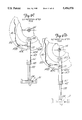
- FIG. 3 is a side elevational view of the rotary placer of the present invention viewed from an opposite side from FIG. 2;
- FIGS. 4A, 4B, 4C, 4D, and 4E are schematic side elevational diagrams of the rotary placer which show the relative position of the arm in relation to the guide track as a carton is moved from a pick position to a place position;
- FIG. 5 is a schematic diagram showing movement of the vacuum cup through one entire revolution of the rotary placer
- FIG. 6 is a top plan view of another embodiment of the present invention with a portion of the frame broken away;
- FIG. 7 is a sectional view along line 7--7 in FIG. 6 with a large portion of the frame broken away;
- FIGS. 8A, 8B, and 8C are side elevational views of the embodiment shown in FIG. 6 illustrating the relative position of the arm in relation to the cam surface as a carton is engaged at the pick position;
- FIGS. 9A, 9B, 9C, 9D and 9E are schematic side elevational views of the embodiment shown in FIG. 6 illustrating secondary motion of the arm at the place position when the rotary placer is used for coupon placement.
- a rotary placer 10 picks up a carton or other blank 11 from a pick position at a magazine stack 13, moves the carton 11 to a conveyor (not shown) at a place position and places the carton 11 on the conveyor for opening and filling.
- the rotary placer 10 includes a frame 12 mounted on a shaft 14 for rotation about a central axis 15.
- a hub 16 and suitable locking members drivably connect the frame 12 to the shaft 14.
- External drive means 17 rotates the shaft 14 and then the frame 12 about the central axis 15.
- the shaft 14 is mounted in suitable bearings to a machine frame shown schematically at 19 wherein the pick and place positions are typically spaced by 90 degrees.
- the rotary placer 10 as shown includes a pair of arms 20 mounted on the frame 12 and having outer ends extending outwardly from the frame 12. At least one arm 20 is used, and the frame can carry four or more arms if desired. Each arm 20 has a gripping member, commonly a pair of vacuum cups 24 adjustably mounted on a bracket 27A which is attached to an outer end of each arm 20 to engage and releasably retain a single carton 11 for removal from the magazine stack 13 and movement to a place position for further handling. The cartons are shown as being erected and placed on a conveyor.
- the rotary placer 10 includes a gear assembly 30 for controlling movement of the vacuum cups 24 (using an orbiting gear and crank, as will be further explained) from a first extended position (FIG.
- FIG. 5 The combined effect of the gear assembly 30 and the guide means 40 on the motion of the vacuum cups 24 through one entire revolution of the rotary placer 10 is illustrated in FIG. 5. Without the use of the guide means 40 the vacuum cups 24 would move along an arcuate path between the pick and the place position with the retracted position being midway between the pick position and the place position. However, the guide means 40 alters the arcuate motion of the vacuum cups 24 such that the vacuum cups 24 reach the extended position at the pick position and retract in a desired controlled path as the frame 12 and arm 20 rotate in the direction indicted by arrow 25, and such that the arm 20 reaches the extended position at the place position and retracts along a similar controlled path.
- the vacuum cups 24 move clockwise laterally at such a speed that the vacuum cups 24 have a zero angular movement relative to a reference plane such as a plane lying on an axis 31 and perpendicular to an axis 31A (See FIG. 5).
- a reference plane such as a plane lying on an axis 31 and perpendicular to an axis 31A (See FIG. 5).
- Linear motion of the vacuum cups 24 toward and away from the cartons in the magazine stack 13 at the pick position permits easy removal of the carton from the magazine stack 13 while linear motion of the vacuum cups 24 at the place position permits the vacuum cups 24 to clear a folded edge of the carton (FIG. 4E).
- the vacuum cups 24 are mounted on axially adjustable vacuum stems which are parallel to the arm 20.
- Hoses 25A connect the vacuum stems 25 to nipples 35 protruding from hub 16.
- the hub 16 is fixed to and rotates with shaft 14 and has passageways carrying vacuum across a rotary sliding seal from a vacuum valve 16A that is held stationary and is connected to a vacuum source in a conventional manner.
- the gear assembly 30 includes a central stationary sun gear 42 and a pair of planetary gears 44, each on a shaft 48 mounted in a separate mounting hub 46.
- Drive shafts 48 each drive a crank 50.
- the central gear 42 is mounted on the central axis 15 of the rotary shaft 14.
- a bearing 54 allows rotation of the rotary shaft 14 within the central gear 42 such that the central gear 42 does not rotate with the shaft 14.
- the central gear 42 is held stationary by a connecting rod.
- a spring 60 bears against plate 62 which in turn maintains a spring load on the rotary seal between vacuum valve 16A and hub 16.
- a connecting rod 58 is attached to a spoke on the central gear 42.
- a connecting rod 59 is attached to the plate 62 and is adjustable to permit adjusting the vacuum connections so that the vacuum to the vacuum cups 24 can be initiated and disconnected at different angular positions of the arms 20.
- Hub 16 and vacuum valve 16A are made of suitable low coefficient of friction materials.
- the planetary gears 44 are driven by teeth 64 of the central gear 42 so that when the frame 12 is rotated, the planetary gears 44 rotate around the drive shafts 48 about axes 39 and orbit about the central axis 15.
- the drive shafts 48 connect inner ends 64 of the respective cranks 50 to the planet gears 44.
- Outer ends 65 of the cranks 50 rotatably attach to an inner end of the respective arm 20 such that when planetary gears 44 rotate, cranks 50 drive about the axis 39 thereby causing the attached arms 20 to reciprocate from the extended position to the retracted position as guided by the guide means 40.
- each of the guide means 40 includes a cam guide track 70 connected to the frame 12 and a guide pin 72 protruding from the arm 20 between the inner and outer ends thereof at an axis 39A and having cam followers 82 thereon to follow along flanges 84 of the respective guide track 70.
- Each guide track 70 is generally linear with a slight hook at an outer end 74 thereof, as shown.
- the linear sections of the guide tracks 70 are positioned at a selected acute angle relative to a bisecting plane 80 defined by the central axis 15 and the axes 39. When the vacuum cups 24 are completely extended or retracted the longitudinal axes of arms 20 also lie on this plane.
- the reciprocating motion of the arms 20 causes the respective guide pin 72 to traverse the associated guide track 70 which thereby displaces the vacuum cups 24 laterally of the plane 80 and laterally of a plane 80A defined by the central axis 15 and the axes 39A during reciprocation of the arms 20.
- Movement of the vacuum cups 24 laterally of the plane 80 and 80A as controlled by the cam guide track 70 permits imparting linear movement to the vacuum cups 24 away from the surfaces of cartons as the frame 12 is rotated adjacent the pick position and the place position.
- the rotary placer 10 has two arms 20 spaced 180 degrees apart from each other, each arm 20 having a gear assembly 30 and guide means 40 of the same construction as described above, however, additional arms and associated gear assemblies and guide means of the same construction as described above may be positioned about the central gear 42 in order to reduce the speed with which the frame 12 must rotate to move the same number of cartons.
- the number of arms 20 positioned around the central gear 42 is limited only by the dimensions of the cartons 11 which are transported and the physical constraints of frame 12.
- the amount of straight line motion of the vacuum cups 24 may be increased or decreased to suit the particular needs of a user by increasing or decreasing the overall size of the rotary placer 10, and more particularly by increasing or decreasing the size of the crank 50 and arm 20.
- the gear ratio between the central gear 42 and the planetary gear 44 is 4:1.
- the gear ratio indicates the frequency with which the vacuum cups 24 are reciprocated from the extended position to the retracted position during one complete revolution of the rotary placer 10.
- the gear ratio may be varied to suit particular needs by changing the size of the gears or by rotating the central gear 44 independent of the shaft 14. If the central gear is rotated in a direction opposite the shaft 14, then the effective gear ratio will increase. If the central gear is rotated in the same direction of the shaft 14, and at a lower speed, then the gear ratio will decrease. If the central gear is rotated in the same direction of the shaft 14, and at a greater speed, then the gear ratio will increase.
- FIGS. 4A through 4E schematically show the positioning of the planetary gears 44, cranks 50, arms 20, vacuum cups 24 and guide tracks 70 in relation to the central gear 42 as the rotary placer 10 picks up the carton 11 at the magazine stack 13, transports the carton 11 and places the carton 11 at the assembly position.
- the vacuum cups 24 engage the carton 11.
- the axes of the crank 50, the arm 20, and vacuum cups 24 at that position are positioned in plane 80 plane defined by the central axis 15 and axis 39 and in plane 80A defined by the central axis 15 and axes 39A.
- the guide pin 72 for that arm 20 is in the hook portion of the guide track 70.
- FIG. 4B shows the rotary placer 10 after 20 degrees counterclockwise rotation.
- the planetary gear 44 and the crank 50 have rotated counterclockwise, thereby reciprocating the arm 20 toward the retracted position.
- the guide pin 72 is guided along the guide track 70 thereby maintaining the vacuum cups 24 first along substantially a linear path in a direction away from and substantially perpendicular to the surface of cartons in magazine 13.
- the guide means 40 enables the plane of the edges of the vacuum cups 24 to tilt clockwise laterally of planes 80 and 80A and pull a carton out of the magazine essentially along a line perpendicular to the carton surface as the frame 12 rotates counter clockwise about the central axis 15.
- FIG. 4C schematically shows the rotary placer 10 about midway between the pick and place positions, the rotary placer having been rotated 40 degrees.
- FIG. 4D schematically shows the rotary placer 10 at the place position and all of the components are aligned the same as in the pick position except that in FIG. 4D the leading flap of the carton 11 has traveled upward in response to the rotational movement of the rotary placer 10 and the leading flap of the carton contacts an abutment or flight 81 of a carton conveyor. The trailing flap of the carton will be folded by the next flight 81.
- FIG. 4E schematically shows the rotary placer 10 after the vacuum cups 24 have disengaged the carton 11 and are moving linearly away from the carton 11 in order to clear the leading flap of the carton 11. The opening of the carton can take place as the cartons reach the place position in a known manner.
- FIGS. 6 and 9 Another exemplary embodiment of the present invention is illustrated in FIGS. 6 and 9.
- the rotary placer 110 includes arms 120 having vacuum cups 124 attached to outer ends thereof for engaging and releasably retaining cartons for movement from a pick position to a place position.
- the rotary placer 110 includes a sun and planetary gear assembly 130 for reciprocating the vacuum cups 124 from a first extended position where the vacuum cups 124 engage and pick up a carton to a retracted position for transport and then out to a second extended position where the carton is placed and released from the vacuum cups.
- Guide means 140 comprising a bell crank 143 pivotally connected to the frame 112 and slidably guiding the respective arm 120, controls the motion of the respective arm 120 such that the arm 120 moves generally linearly away from a carton along line perpendicular to a magazine 13 at the pick position when the vacuum cups 124 engage carton 11 and away from a support at the place position where the vacuum cups 124 release the carton 11.
- the vacuum cups 124 move clockwise laterally at such a speed that the planes of the edges of the vacuum cups 124 have substantially a zero angular movement relative to the plane of the magazine.
- the gear assembly 130 includes a central gear 142, planetary gears 144, each drivably connected to a separate drive shaft 148, which are mounted in hubs 146.
- the central gear 142 is mounted on the rotary shaft 114 which has an axis 115.
- a circular cam is utilized, as will be explained, and the cam is preferably held stationary along with the central gear 142.
- a cam plate 153 has a hub 157 that rotatably mounts the shaft 114 through a bearing 154.
- the bearing 154 allows the shaft 114 to rotate within the central gear 142.
- central gear 142 is held on the cam plate 153 by bolts 159 that extend through spacers.
- the gear 142 and hub 157 are held axially positioned by a pair of clamp collars 163 on the shaft 114.
- the planetary gears 144 engage teeth 164 of the central gear 142.
- the mounting hubs 146 are fixed to the frame 112 so that when the frame 112 is rotated as shaft 114 is driven, the planetary gears 144 rotate about an axis 139 of the drive shaft 148 carried in hubs 146 and orbit about the central axis 115.
- the drive shafts 148 drivably mount inner ends 164 of the respective cranks 150.
- Outer ends 165 of cranks 150 are pivotally attached to the inner ends of the respective arms 120 such that when the planetary gear 144 rotates, the cranks 150 are driven about the axes 139, thereby causing the arms 120 to reciprocate from the extended position to the retracted position as the arms 120 are carried with the frame 112.
- the guide means 140 includes a box cam 137 mounted on plate 153 and having a cam track 141 formed therein.
- Bell crank 143 has a first arm 143C that mounts a cam follower 143B, and a second arm 143A having a linear bearing 145 pivotally mounted thereon about an axis 139A parallel to axes 139 and 115.
- the arms 120 are slidably mounted in the respective linear bearing 145.
- the linear bearings 145 pivot as needed about pin 161 to accommodate the linear movement of arms 120.
- the box cam 137 is usually fixed to a mounting frame and encircles the central gear 142; however, it may be desirable to move the box cam 137 at the pick and/or place position.
- Hubs 169 mount shaft 171 of bell crank 143 on bearings.
- the first arm 143A of each bell crank 143 is on an opposite side of a wall 112A of frame 112 from the second arm 143C so the cam followers 143B can move along cam track 141.
- the cam track 141 will cause the bell crank 143 to pivot relative to frame 112 and cause the linear bearings 145 on the first arm 143A of the bell crank 143 to change position.
- the cam track 141 has at least one cam lobe 155 formed where the distance between the cam track 141 and central axis 115 changes.
- the cam track 141 changes the position of the linear bearings 145 as the frame 112 rotates counterclockwise about the central axis 115.
- the arms 120 pivot clockwise with an angular speed as the frame 112 rotates so as to have substantially zero annular movement relative to the cartons in the magazine 13 at the pick position.
- the vacuum cups 124 are displaced laterally of a reference plane 180 defined by the central axis 115 and the axes 139 and a reference plane 180A defined by the central axis 115 and axes 139A as the frame 112 rotates counterclockwise about the central axis 115.
- the movement of the arms 120 and thus vacuum cups 124 is proportional to the amount of movement of the bell crank 143 as controlled by cam track 141.
- Additional cam lobes may be placed along the cam track 141 at desired locations to cause additional desired motion of the vacuum cups 124 such as, for example, linear motion at the place position. Also, by changing the shape of a cam lobe 155' at the place position, for example, it is possible to induce secondary motion of the vacuum cups 124 such that a blank is kicked forward in the direction of and at the same speed as the blank conveyor in order to assure accurate placement of the blank on the blank conveyor (see FIGS. 9A-9E). Secondary motion is particularly desirable for coupon placement in order to allow glue on the backside of the coupon to adequately adhere to the moving blank.
- the linear bearings 145 let the arms 120 slide easily and permit the cranks 150 to rotate and reciprocate the arms 120 from the extended position to the retracted position.
- FIGS. 8A, 8B and 8C schematically show the positioning of the left side planetary gear 144, crank 150, arm 120, vacuum cups 124, linear bearing 145, and bell crank 143 in relation to the central gear 142 as the rotary placer 110 picks up the carton 11 at the magazine 13.
- the figures have been illustrated with the wall 112A of frame 112 broken away in large parts to show the cam track 141, while also leaving the bell crank 143 in solid lines.
- FIG. 8A the pivot shaft 171 of the left bell crank 143 is shown with cam follower 143B approaching the cam lobe 155. Clockwise rotation of the left crank 150 has caused the arm 120 to pivot on the linear bearing 145 clockwise while the arm 120 slides within the linear bearing 145, in approach of the pick position.
- FIG. 8B the left linear bearing 145 and second arm 143C of the bell crank 143 are aligned or on center with the reference plane 180 for picking up the carton from magazine stack 13.
- the first arm 143A of the bell crank 143 is shown pivoting to move the second arm 143C as cam follower 143B traverses the cam lobe 155 at the pick position, which causes the second arm 143C of the bell crank 143 to pivot clockwise about pivot shaft 171 at a speed synchronized with the counterclockwise rotation of the frame 112 such that the vacuum cups 124 move linearly away from the magazine 13 at the pick position along a line substantially perpendicular to the surface of cartons or sleeves in magazine 13.
- FIGS. 9A-9E schematically show the positioning of the planetary gear 144, crank 150, arm 120, vacuum cups 124, linear bearing 145 and bell crank 143 in relation to a cam lobe 155' as the rotary placer 110 places a coupon "C" on a carton 11'.
- the rotary placer can be used for applying labels or coupons onto carton surfaces at a high rate.
- the figures have been illustrated with the wall 112A of frame 112 broken away in large parts to show the cam lobe 155'.
- cam follower 143B traverses the cam lobe 155' it causes the arm 120 to kick forward at substantially the same speed and in the same direction as the carton 11' on the carton conveyor.
- This 'kick" or secondary motion is to ensure that the coupon can be placed on a carton surface while traveling at the same speed as the carton so it will not slide on the surface and any adhesive used will secure the coupon on the carton or other object.
- FIG. 9A the cam follower 143B is on the cam lobe 155' and the vacuum cups 124 are shown in approach of the place position and the coupon C is not yet in contact with the carton 11'.
- FIGS. 9B, 9C and 9D show the rotary placer 110 undergoing secondary accelerated forward motion as the vacuum cups 124 remain in contact with the coupon C through approximately at least four degrees of rotation through the place position.
- the coupon is moved at the same speed as the carton as it contacts the carton for a short distance before the vacuum is released and the vacuum cups 24 drawn linearly away to clear obstructions, such as conveyor flight 81.
- the vacuum may be released either just after the initial kick or the end of the secondary motion.
- FIG. 9E shows the vacuum cups 124 after secondary motion is complete and after the vacuum has been cut off.
- the vacuum cups are shown being pulled linearly away from the carton in a manner similar to the motion at the pick position, except that the secondary motion caused by the cam lobe 155' has in essence expanded the linear dimensions of the place position and altered the speed of movement in direction of movement of the carton.
- secondar motion is particularly useful for coupon placement, but it is also useful any time the object being placed has to move at the same speed as the conveyor on or object which it is being placed for a short distance.
- the rotary placer 10,110 of the present invention rotates continuously at a fixed speed and effectuates straight-line picking using cam guide means which alter the direction of movement of the arm while the arm is reciprocated by a crank.
- the present invention is more reliable to operate and easier to manufacture than other rotary placers.
Abstract
Description
Claims (16)
Priority Applications (1)
| Application Number | Priority Date | Filing Date | Title |
|---|---|---|---|
| US08/048,853 US5456570A (en) | 1993-04-19 | 1993-04-19 | Rotary placer |
Applications Claiming Priority (1)
| Application Number | Priority Date | Filing Date | Title |
|---|---|---|---|
| US08/048,853 US5456570A (en) | 1993-04-19 | 1993-04-19 | Rotary placer |
Publications (1)
| Publication Number | Publication Date |
|---|---|
| US5456570A true US5456570A (en) | 1995-10-10 |
Family
ID=21956799
Family Applications (1)
| Application Number | Title | Priority Date | Filing Date |
|---|---|---|---|
| US08/048,853 Expired - Lifetime US5456570A (en) | 1993-04-19 | 1993-04-19 | Rotary placer |
Country Status (1)
| Country | Link |
|---|---|
| US (1) | US5456570A (en) |
Cited By (34)
| Publication number | Priority date | Publication date | Assignee | Title |
|---|---|---|---|---|
| EP0748277A1 (en) * | 1994-12-30 | 1996-12-18 | Riverwood International Corporation | Carton feeder assembly |
| EP0765828A1 (en) * | 1995-09-29 | 1997-04-02 | CML Handling Technology S.p.A. | Destacker for small flat packages such as audio/video cassettes and the like |
| US5910078A (en) * | 1995-09-28 | 1999-06-08 | H. J. Langen & Sons, Inc. | Rotary object feeder |
| US5928123A (en) * | 1996-07-17 | 1999-07-27 | Davis Engineering Llc | Vacuum holder for automated carton erecting machine |
| US5974769A (en) * | 1997-08-01 | 1999-11-02 | Uniflex, Inc. | Automated container insert device |
| US6033173A (en) * | 1997-08-11 | 2000-03-07 | Industrial Technology Research Institute | Automated access method and device for use with lead frame magazine end cover plates during IC packaging process |
| US6168149B1 (en) * | 1997-09-04 | 2001-01-02 | G.D Societa' Per Azioni | Method and unit for feeding blanks to a user machine |
| US6273242B1 (en) | 2000-02-29 | 2001-08-14 | Riverwood International Corporation | Rotary transfer apparatus with an in-line cam mechanism |
| US6442914B1 (en) | 1999-11-29 | 2002-09-03 | Rapid Automated Systems, Inc. | Tagging system for inserting tags into plant containers |
| US20020193895A1 (en) * | 2001-06-18 | 2002-12-19 | Ziqiang Qian | Enhanced encoder for synchronizing multimedia files into an audio bit stream |
| US20040013508A1 (en) * | 2001-09-05 | 2004-01-22 | Kelly Ziegler | Rotary pick and place technology |
| US6837664B2 (en) | 2002-09-10 | 2005-01-04 | Douglas Machine, Inc. | Multiple head rotary set-up |
| US20050008470A1 (en) * | 2003-07-09 | 2005-01-13 | Petar Baclija | Rotary object feeder |
| DE10346416A1 (en) * | 2003-10-07 | 2005-05-04 | Rovema Gmbh | Device for transferring folded cartons |
| DE102004005397A1 (en) * | 2004-02-04 | 2005-08-25 | Rovema Verpackungsmaschinen Gmbh | Transfer and unfolding machine for folded boxes or packets has arm with suction cups at each end moving longitudinally in guides on rotor, moving boxes from magazine to conveyer belt with upstanding vanes |
| US20070257416A1 (en) * | 2006-02-01 | 2007-11-08 | Graphic Packaging International, Inc. | Rotary carton feeder |
| US20070293383A1 (en) * | 2006-05-15 | 2007-12-20 | Pearson Packaging Systems | Fan-Folding Mechanism for a Case Erector |
| US20080170930A1 (en) * | 2007-01-11 | 2008-07-17 | Hubertus Heigl | Transport assembly |
| DE19845384B4 (en) * | 1998-10-02 | 2008-08-21 | Robert Bosch Gmbh | Device for transferring flat objects, in particular folding boxes |
| WO2009034467A2 (en) * | 2007-09-14 | 2009-03-19 | C.M.S. Costruzione Macchine Speciali S.R.L. | Apparatus for unpiling containers, particularly pastry containers |
| US20100150686A1 (en) * | 2007-10-05 | 2010-06-17 | Multitest Elektronische Systeme Gmbh | Handler for electronic components, in particular ic's, comprising a pneumatic cylinder displacement unit for moving plungers |
| US20140250651A1 (en) * | 2013-03-07 | 2014-09-11 | Cosmetic Laboratories Of America, Llc | Article assembly apparatus having rotary article pick and place |
| EP2821216A1 (en) * | 2013-07-02 | 2015-01-07 | Martijn Arnold Van Rossum | Device for unfolding a flat-folded tube |
| US20150031517A1 (en) * | 2013-07-23 | 2015-01-29 | G.D Societa' Per Azioni | Packing method and unit for folding a blank on a packing machine |
| US9238558B2 (en) | 2012-09-12 | 2016-01-19 | Graphic Packaging International, Inc. | Reciprocating placer system |
| US9839937B1 (en) | 2010-11-10 | 2017-12-12 | Smead Manufacturing Company | Method of making a powder coated protected prong file fastener |
| US20180319525A1 (en) * | 2017-05-04 | 2018-11-08 | Afa Systems Ltd. | Method and apparatus for reconfiguring containers |
| US20190127099A1 (en) * | 2012-04-24 | 2019-05-02 | H. J. Paul Langen | Method and system for order fulfilment |
| US10287118B2 (en) * | 2013-12-20 | 2019-05-14 | Tetra Laval Holdings & Finance S.A. | Apparatus and method for feeding carton blanks from a magazine to carriers |
| US20220048658A1 (en) * | 2014-03-11 | 2022-02-17 | H. J. Paul Langen | Method and system for order fulfilment |
| EP4008641A1 (en) | 2020-12-07 | 2022-06-08 | A.C.M.I. - Societa' Per Azioni | Cartoning apparatus |
| US20220194042A1 (en) * | 2020-12-22 | 2022-06-23 | Dart Container Corporation | Container forming machine having a blank stacker assembly |
| US11390049B2 (en) | 2019-11-07 | 2022-07-19 | H. J. Paul Langen | Method and apparatus for erecting cartons |
| US11752723B2 (en) | 2019-11-07 | 2023-09-12 | H. J. Paul Langen | Method and apparatus for erecting cartons and for order fulfilment and packing |
Citations (17)
| Publication number | Priority date | Publication date | Assignee | Title |
|---|---|---|---|---|
| US2887022A (en) * | 1956-08-20 | 1959-05-19 | Fibreboard Paper Products Corp | Machine for setting up cartons |
| US2936681A (en) * | 1957-01-30 | 1960-05-17 | Ex Cell O Corp | Container blank feeder mechanism |
| US3599541A (en) * | 1969-05-22 | 1971-08-17 | Ex Cell O Corp | Container blank variable-speed feeder apparatus |
| US3633470A (en) * | 1969-02-12 | 1972-01-11 | Pitters Proprietary Ltd | Package feeder apparatus |
| US3937131A (en) * | 1974-07-19 | 1976-02-10 | Ex-Cell-O Corporation | Carton feeding apparatus |
| US4194442A (en) * | 1977-03-18 | 1980-03-25 | Guglielmo Martelli | Device for picking up semi-rigid sheet-like elements from a magazine and transferring them onto a conveyor |
| US4643633A (en) * | 1984-02-17 | 1987-02-17 | Minnesota Automation | Rotary transfer device |
| US4735600A (en) * | 1986-02-26 | 1988-04-05 | Robert Bosch Gmbh | Apparatus for separating and erecting folding boxes |
| US4802324A (en) * | 1988-04-14 | 1989-02-07 | Minnesota Automation, Inc. | Vertical cartoning assembly and method |
| US4854930A (en) * | 1987-07-30 | 1989-08-08 | I.M.A. - Industria Macchine Automatiche - Spa | Apparatus for the supply of blanks of packaging material and in particular for the supply and erection of flat folded tubular blanks as packaging cases in "blister" packaging machines |
| US4881934A (en) * | 1988-02-27 | 1989-11-21 | Kliklok Corporation | Rotary transfer mechanism |
| US4902192A (en) * | 1988-05-19 | 1990-02-20 | Minnesota Automation, Inc. | Article control assembly for article transfer device |
| US4901843A (en) * | 1986-04-02 | 1990-02-20 | Minnesota Automation, Inc. | Advancing motion rotary apparatus |
| US5019029A (en) * | 1989-11-13 | 1991-05-28 | The Mead Corporation | Machine for erecting sleeve type cartons |
| US5104369A (en) * | 1989-11-13 | 1992-04-14 | The Mead Corporation | Method for erecting sleeve type carton |
| US5105931A (en) * | 1990-10-16 | 1992-04-21 | Minnesota Automation, Inc. | Article control assembly |
| US5110282A (en) * | 1988-07-13 | 1992-05-05 | Nissei Asb Machine Co., Ltd. | Preform carrying apparatus |
-
1993
- 1993-04-19 US US08/048,853 patent/US5456570A/en not_active Expired - Lifetime
Patent Citations (17)
| Publication number | Priority date | Publication date | Assignee | Title |
|---|---|---|---|---|
| US2887022A (en) * | 1956-08-20 | 1959-05-19 | Fibreboard Paper Products Corp | Machine for setting up cartons |
| US2936681A (en) * | 1957-01-30 | 1960-05-17 | Ex Cell O Corp | Container blank feeder mechanism |
| US3633470A (en) * | 1969-02-12 | 1972-01-11 | Pitters Proprietary Ltd | Package feeder apparatus |
| US3599541A (en) * | 1969-05-22 | 1971-08-17 | Ex Cell O Corp | Container blank variable-speed feeder apparatus |
| US3937131A (en) * | 1974-07-19 | 1976-02-10 | Ex-Cell-O Corporation | Carton feeding apparatus |
| US4194442A (en) * | 1977-03-18 | 1980-03-25 | Guglielmo Martelli | Device for picking up semi-rigid sheet-like elements from a magazine and transferring them onto a conveyor |
| US4643633A (en) * | 1984-02-17 | 1987-02-17 | Minnesota Automation | Rotary transfer device |
| US4735600A (en) * | 1986-02-26 | 1988-04-05 | Robert Bosch Gmbh | Apparatus for separating and erecting folding boxes |
| US4901843A (en) * | 1986-04-02 | 1990-02-20 | Minnesota Automation, Inc. | Advancing motion rotary apparatus |
| US4854930A (en) * | 1987-07-30 | 1989-08-08 | I.M.A. - Industria Macchine Automatiche - Spa | Apparatus for the supply of blanks of packaging material and in particular for the supply and erection of flat folded tubular blanks as packaging cases in "blister" packaging machines |
| US4881934A (en) * | 1988-02-27 | 1989-11-21 | Kliklok Corporation | Rotary transfer mechanism |
| US4802324A (en) * | 1988-04-14 | 1989-02-07 | Minnesota Automation, Inc. | Vertical cartoning assembly and method |
| US4902192A (en) * | 1988-05-19 | 1990-02-20 | Minnesota Automation, Inc. | Article control assembly for article transfer device |
| US5110282A (en) * | 1988-07-13 | 1992-05-05 | Nissei Asb Machine Co., Ltd. | Preform carrying apparatus |
| US5019029A (en) * | 1989-11-13 | 1991-05-28 | The Mead Corporation | Machine for erecting sleeve type cartons |
| US5104369A (en) * | 1989-11-13 | 1992-04-14 | The Mead Corporation | Method for erecting sleeve type carton |
| US5105931A (en) * | 1990-10-16 | 1992-04-21 | Minnesota Automation, Inc. | Article control assembly |
Cited By (61)
| Publication number | Priority date | Publication date | Assignee | Title |
|---|---|---|---|---|
| EP0748277A4 (en) * | 1994-12-30 | 1998-09-30 | Riverwood Int Corp | Carton feeder assembly |
| EP0748277A1 (en) * | 1994-12-30 | 1996-12-18 | Riverwood International Corporation | Carton feeder assembly |
| US5910078A (en) * | 1995-09-28 | 1999-06-08 | H. J. Langen & Sons, Inc. | Rotary object feeder |
| US5997458A (en) * | 1995-09-28 | 1999-12-07 | Langen Packaging Inc. | Rotary object feeder |
| EP0765828A1 (en) * | 1995-09-29 | 1997-04-02 | CML Handling Technology S.p.A. | Destacker for small flat packages such as audio/video cassettes and the like |
| US6179004B1 (en) | 1996-07-17 | 2001-01-30 | Davis Engineering Llc | Vacuum holder for automated carton erecting machine |
| US5928123A (en) * | 1996-07-17 | 1999-07-27 | Davis Engineering Llc | Vacuum holder for automated carton erecting machine |
| US5974769A (en) * | 1997-08-01 | 1999-11-02 | Uniflex, Inc. | Automated container insert device |
| US6033173A (en) * | 1997-08-11 | 2000-03-07 | Industrial Technology Research Institute | Automated access method and device for use with lead frame magazine end cover plates during IC packaging process |
| US6168149B1 (en) * | 1997-09-04 | 2001-01-02 | G.D Societa' Per Azioni | Method and unit for feeding blanks to a user machine |
| DE19845384B4 (en) * | 1998-10-02 | 2008-08-21 | Robert Bosch Gmbh | Device for transferring flat objects, in particular folding boxes |
| US6442914B1 (en) | 1999-11-29 | 2002-09-03 | Rapid Automated Systems, Inc. | Tagging system for inserting tags into plant containers |
| US6273242B1 (en) | 2000-02-29 | 2001-08-14 | Riverwood International Corporation | Rotary transfer apparatus with an in-line cam mechanism |
| EP1196339A1 (en) * | 2000-02-29 | 2002-04-17 | Riverwood International Corporation | Rotary transfer apparatus with an in-line cam |
| EP1196339A4 (en) * | 2000-02-29 | 2004-06-30 | Riverwood Int Corp | Rotary transfer apparatus with an in-line cam |
| US20020193895A1 (en) * | 2001-06-18 | 2002-12-19 | Ziqiang Qian | Enhanced encoder for synchronizing multimedia files into an audio bit stream |
| EP1448460A2 (en) * | 2001-09-05 | 2004-08-25 | Graphic Packaging International, Inc. | Rotary pick and place technology |
| EP1448460A4 (en) * | 2001-09-05 | 2007-05-23 | Graphic Packaging Int Inc | Rotary pick and place technology |
| US7273343B2 (en) | 2001-09-05 | 2007-09-25 | Graphic Packaging International, Inc. | Rotary pick and place technology |
| US20040013508A1 (en) * | 2001-09-05 | 2004-01-22 | Kelly Ziegler | Rotary pick and place technology |
| US6837664B2 (en) | 2002-09-10 | 2005-01-04 | Douglas Machine, Inc. | Multiple head rotary set-up |
| US7326165B2 (en) | 2003-07-09 | 2008-02-05 | Langen Packaging Inc. | Rotary object feeder |
| US20050008470A1 (en) * | 2003-07-09 | 2005-01-13 | Petar Baclija | Rotary object feeder |
| US7081079B2 (en) * | 2003-07-09 | 2006-07-25 | Langen Packaging Inc. | Rotary object feeder |
| US20060264311A1 (en) * | 2003-07-09 | 2006-11-23 | Langen Packaging Inc. | Rotary object feeder |
| DE10346416A1 (en) * | 2003-10-07 | 2005-05-04 | Rovema Gmbh | Device for transferring folded cartons |
| DE102004005397A1 (en) * | 2004-02-04 | 2005-08-25 | Rovema Verpackungsmaschinen Gmbh | Transfer and unfolding machine for folded boxes or packets has arm with suction cups at each end moving longitudinally in guides on rotor, moving boxes from magazine to conveyer belt with upstanding vanes |
| US20070257416A1 (en) * | 2006-02-01 | 2007-11-08 | Graphic Packaging International, Inc. | Rotary carton feeder |
| US7695421B2 (en) | 2006-02-01 | 2010-04-13 | Graphic Packaging International, Inc. | Rotary carton feeder |
| US8282537B2 (en) | 2006-05-15 | 2012-10-09 | Frito-Lay North America, Inc. | Fan-folding mechanism for a case erector |
| US20070293383A1 (en) * | 2006-05-15 | 2007-12-20 | Pearson Packaging Systems | Fan-Folding Mechanism for a Case Erector |
| US7585265B2 (en) | 2006-05-15 | 2009-09-08 | Frito-Lay North America, Inc. | Fan-folding mechanism for a case erector |
| US20090291816A1 (en) * | 2006-05-15 | 2009-11-26 | Frito-Lay North America, Inc. | Fan-folding mechanism for a case erector |
| US20080170930A1 (en) * | 2007-01-11 | 2008-07-17 | Hubertus Heigl | Transport assembly |
| US8584830B2 (en) * | 2007-01-11 | 2013-11-19 | Hubertus Heigl | Transport assembly |
| WO2009034467A2 (en) * | 2007-09-14 | 2009-03-19 | C.M.S. Costruzione Macchine Speciali S.R.L. | Apparatus for unpiling containers, particularly pastry containers |
| US20110033277A1 (en) * | 2007-09-14 | 2011-02-10 | C.M.S. Costruzione Macchine Speciali S.R.L. | Apparatus for unpiling containers, particularly pastry containers |
| WO2009034467A3 (en) * | 2007-09-14 | 2009-06-11 | C M S Costruzione Macchine Spe | Apparatus for unpiling containers, particularly pastry containers |
| US20100150686A1 (en) * | 2007-10-05 | 2010-06-17 | Multitest Elektronische Systeme Gmbh | Handler for electronic components, in particular ic's, comprising a pneumatic cylinder displacement unit for moving plungers |
| US8684168B2 (en) * | 2007-10-05 | 2014-04-01 | Multitest Elektronische Systeme Gmbh | Handler for electronic components, in particular IC'S, comprising a pneumatic cylinder displacement unit for moving plungers |
| US9839937B1 (en) | 2010-11-10 | 2017-12-12 | Smead Manufacturing Company | Method of making a powder coated protected prong file fastener |
| US10556713B2 (en) * | 2012-04-24 | 2020-02-11 | H. J. Paul Langen | Method and system for order fulfilment |
| US11136153B2 (en) | 2012-04-24 | 2021-10-05 | H. J. Paul Langen | Method and system for order fulfilment |
| US20190127099A1 (en) * | 2012-04-24 | 2019-05-02 | H. J. Paul Langen | Method and system for order fulfilment |
| US9238558B2 (en) | 2012-09-12 | 2016-01-19 | Graphic Packaging International, Inc. | Reciprocating placer system |
| US20140250651A1 (en) * | 2013-03-07 | 2014-09-11 | Cosmetic Laboratories Of America, Llc | Article assembly apparatus having rotary article pick and place |
| EP2821216A1 (en) * | 2013-07-02 | 2015-01-07 | Martijn Arnold Van Rossum | Device for unfolding a flat-folded tube |
| US20150031517A1 (en) * | 2013-07-23 | 2015-01-29 | G.D Societa' Per Azioni | Packing method and unit for folding a blank on a packing machine |
| US9821526B2 (en) * | 2013-07-23 | 2017-11-21 | G. D. Societa' Per Azioni | Packing method and unit for folding a blank on a packing machine |
| US10287118B2 (en) * | 2013-12-20 | 2019-05-14 | Tetra Laval Holdings & Finance S.A. | Apparatus and method for feeding carton blanks from a magazine to carriers |
| US20220048658A1 (en) * | 2014-03-11 | 2022-02-17 | H. J. Paul Langen | Method and system for order fulfilment |
| US10850881B2 (en) * | 2017-05-04 | 2020-12-01 | Afa Systems Ltd. | Method and apparatus for reconfiguring containers |
| US20210039816A1 (en) * | 2017-05-04 | 2021-02-11 | Afa Systems Ltd. | Method and apparatus for reconfiguring containers |
| US20180319525A1 (en) * | 2017-05-04 | 2018-11-08 | Afa Systems Ltd. | Method and apparatus for reconfiguring containers |
| US11820542B2 (en) * | 2017-05-04 | 2023-11-21 | Afa Systems Ltd. | Method and apparatus for reconfiguring containers |
| US11390049B2 (en) | 2019-11-07 | 2022-07-19 | H. J. Paul Langen | Method and apparatus for erecting cartons |
| US11752723B2 (en) | 2019-11-07 | 2023-09-12 | H. J. Paul Langen | Method and apparatus for erecting cartons and for order fulfilment and packing |
| US11897222B2 (en) | 2019-11-07 | 2024-02-13 | H. J. Paul Langen | Method and apparatus for erecting cartons |
| EP4008641A1 (en) | 2020-12-07 | 2022-06-08 | A.C.M.I. - Societa' Per Azioni | Cartoning apparatus |
| US20220194042A1 (en) * | 2020-12-22 | 2022-06-23 | Dart Container Corporation | Container forming machine having a blank stacker assembly |
| US11623422B2 (en) * | 2020-12-22 | 2023-04-11 | Dart Container Corporation | Container forming machine having a blank stacker assembly |
Similar Documents
| Publication | Publication Date | Title |
|---|---|---|
| US5456570A (en) | Rotary placer | |
| EP0331325B1 (en) | Rotary transfer mechanism | |
| US8047530B2 (en) | Rotary transfer mechanism | |
| JP2794096B2 (en) | Continuous and intermittent feed interface | |
| US2601481A (en) | Means for opening and loading carton blanks on the conveyer of a packaging machine | |
| US5613828A (en) | Handling partly completed containers | |
| EP0565644A1 (en) | Feeder mechanism for sleeve type cartons | |
| US8342508B2 (en) | System for transferring objects | |
| JPH03200518A (en) | Device for transporting flat articles | |
| JPH03200516A (en) | Device for delivery of flat object | |
| KR920006489B1 (en) | Carton handle applicator | |
| US4450950A (en) | Work piece transfer mechanism | |
| CA2451145C (en) | Rotary pick and place technology | |
| JPS60229743A (en) | Device for extracting, erecting and delivering folding corrugated box | |
| US3937131A (en) | Carton feeding apparatus | |
| AU2002332859A1 (en) | Rotary pick and place technology | |
| US4773525A (en) | Transfer conveyor for packaging plant | |
| US5112430A (en) | Apparatus for applying a sheet to a substrate | |
| EP0767736B1 (en) | Carton hold-down element for rotary feeders | |
| US5664400A (en) | Carton blanks handling mechanism | |
| US6273242B1 (en) | Rotary transfer apparatus with an in-line cam mechanism | |
| US20190276245A1 (en) | Case turner | |
| EP0693425A2 (en) | Handling partly completed containers | |
| US3701525A (en) | Apparatus and method for erecting a carrier | |
| EP1419969A1 (en) | A device and method for picking up and erecting carton blanks |
Legal Events
| Date | Code | Title | Description |
|---|---|---|---|
| AS | Assignment |
Owner name: BILL DAVIS ENGINEERING, INC., MINNESOTA Free format text: ASSIGNMENT OF ASSIGNORS INTEREST;ASSIGNORS:DAVIS, ELLIS W., JR.;ERICKSON, SCOTT C.;REEL/FRAME:006534/0956 Effective date: 19930415 |
|
| STPP | Information on status: patent application and granting procedure in general |
Free format text: APPLICATION UNDERGOING PREEXAM PROCESSING |
|
| AS | Assignment |
Owner name: DAVIS ENGINEERING LLC, MINNESOTA Free format text: ASSIGNMENT OF ASSIGNORS INTEREST;ASSIGNOR:BILL DAVIS ENGINEERING, INC.;REEL/FRAME:007961/0482 Effective date: 19960513 |
|
| FEPP | Fee payment procedure |
Free format text: PAYOR NUMBER ASSIGNED (ORIGINAL EVENT CODE: ASPN); ENTITY STATUS OF PATENT OWNER: LARGE ENTITY |
|
| FEPP | Fee payment procedure |
Free format text: PAT HLDR NO LONGER CLAIMS SMALL ENT STAT AS SMALL BUSINESS (ORIGINAL EVENT CODE: LSM2); ENTITY STATUS OF PATENT OWNER: LARGE ENTITY |
|
| FPAY | Fee payment |
Year of fee payment: 4 |
|
| FPAY | Fee payment |
Year of fee payment: 8 |
|
| AS | Assignment |
Owner name: DOUGLAS MACHINE INC., MINNESOTA Free format text: MERGER;ASSIGNORS:DAVIS ENGINEERING LLC;DOUGLAS MACHINE INC.;REEL/FRAME:018120/0715 Effective date: 20021230 |
|
| FEPP | Fee payment procedure |
Free format text: PAYOR NUMBER ASSIGNED (ORIGINAL EVENT CODE: ASPN); ENTITY STATUS OF PATENT OWNER: LARGE ENTITY Free format text: PAYER NUMBER DE-ASSIGNED (ORIGINAL EVENT CODE: RMPN); ENTITY STATUS OF PATENT OWNER: LARGE ENTITY |
|
| FPAY | Fee payment |
Year of fee payment: 12 |