US5458187A - Dual core air-to-air heat exchanger - Google Patents
Dual core air-to-air heat exchanger Download PDFInfo
- Publication number
- US5458187A US5458187A US08/160,523 US16052393A US5458187A US 5458187 A US5458187 A US 5458187A US 16052393 A US16052393 A US 16052393A US 5458187 A US5458187 A US 5458187A
- Authority
- US
- United States
- Prior art keywords
- air
- channels
- wall
- exchanger
- indoor
- Prior art date
- Legal status (The legal status is an assumption and is not a legal conclusion. Google has not performed a legal analysis and makes no representation as to the accuracy of the status listed.)
- Expired - Lifetime
Links
Images


Classifications
-
- F—MECHANICAL ENGINEERING; LIGHTING; HEATING; WEAPONS; BLASTING
- F28—HEAT EXCHANGE IN GENERAL
- F28D—HEAT-EXCHANGE APPARATUS, NOT PROVIDED FOR IN ANOTHER SUBCLASS, IN WHICH THE HEAT-EXCHANGE MEDIA DO NOT COME INTO DIRECT CONTACT
- F28D9/00—Heat-exchange apparatus having stationary plate-like or laminated conduit assemblies for both heat-exchange media, the media being in contact with different sides of a conduit wall
- F28D9/0025—Heat-exchange apparatus having stationary plate-like or laminated conduit assemblies for both heat-exchange media, the media being in contact with different sides of a conduit wall the conduits being formed by zig-zag bend plates
-
- F—MECHANICAL ENGINEERING; LIGHTING; HEATING; WEAPONS; BLASTING
- F24—HEATING; RANGES; VENTILATING
- F24F—AIR-CONDITIONING; AIR-HUMIDIFICATION; VENTILATION; USE OF AIR CURRENTS FOR SCREENING
- F24F12/00—Use of energy recovery systems in air conditioning, ventilation or screening
- F24F12/001—Use of energy recovery systems in air conditioning, ventilation or screening with heat-exchange between supplied and exhausted air
-
- F—MECHANICAL ENGINEERING; LIGHTING; HEATING; WEAPONS; BLASTING
- F28—HEAT EXCHANGE IN GENERAL
- F28F—DETAILS OF HEAT-EXCHANGE AND HEAT-TRANSFER APPARATUS, OF GENERAL APPLICATION
- F28F21/00—Constructions of heat-exchange apparatus characterised by the selection of particular materials
- F28F21/06—Constructions of heat-exchange apparatus characterised by the selection of particular materials of plastics material
- F28F21/067—Details
-
- F—MECHANICAL ENGINEERING; LIGHTING; HEATING; WEAPONS; BLASTING
- F28—HEAT EXCHANGE IN GENERAL
- F28F—DETAILS OF HEAT-EXCHANGE AND HEAT-TRANSFER APPARATUS, OF GENERAL APPLICATION
- F28F2240/00—Spacing means
-
- Y—GENERAL TAGGING OF NEW TECHNOLOGICAL DEVELOPMENTS; GENERAL TAGGING OF CROSS-SECTIONAL TECHNOLOGIES SPANNING OVER SEVERAL SECTIONS OF THE IPC; TECHNICAL SUBJECTS COVERED BY FORMER USPC CROSS-REFERENCE ART COLLECTIONS [XRACs] AND DIGESTS
- Y02—TECHNOLOGIES OR APPLICATIONS FOR MITIGATION OR ADAPTATION AGAINST CLIMATE CHANGE
- Y02B—CLIMATE CHANGE MITIGATION TECHNOLOGIES RELATED TO BUILDINGS, e.g. HOUSING, HOUSE APPLIANCES OR RELATED END-USER APPLICATIONS
- Y02B30/00—Energy efficient heating, ventilation or air conditioning [HVAC]
- Y02B30/56—Heat recovery units
-
- Y—GENERAL TAGGING OF NEW TECHNOLOGICAL DEVELOPMENTS; GENERAL TAGGING OF CROSS-SECTIONAL TECHNOLOGIES SPANNING OVER SEVERAL SECTIONS OF THE IPC; TECHNICAL SUBJECTS COVERED BY FORMER USPC CROSS-REFERENCE ART COLLECTIONS [XRACs] AND DIGESTS
- Y10—TECHNICAL SUBJECTS COVERED BY FORMER USPC
- Y10S—TECHNICAL SUBJECTS COVERED BY FORMER USPC CROSS-REFERENCE ART COLLECTIONS [XRACs] AND DIGESTS
- Y10S165/00—Heat exchange
- Y10S165/909—Regeneration
Definitions
- This invention relates to an air exchanger for replacing indoor air in an enclosure with outdoor air and, more particularly, to an air exchanger which includes a heat exchanger which changes the temperature of the outdoor air such that it enters the room at a temperature approaching that of the indoor air temperature.
- the present invention has been made in view of the inadequacies of the prior art and has as an object to provide an air exchanger which continuously supplies fresh air to the indoors by constantly exchanging indoor air with outdoor air.
- the air exchanger of the present invention comprises a housing including a front wall, a rear wall, a top wall and a bottom wall.
- the front wall includes a from air inlet and a front air outlet
- the rear wall includes a rear air inlet and a rear air outlet.
- the air exchanger further comprises a heat exchanger for transferring heat between the indoor and outdoor air streams as they travel through the air exchanger.
- the heat exchanger extends between the top wall and the bottom wall, and has a continuously corrugated and pleated structure which defines a plurality of alternating first channels and second channels.
- the first channels are open toward the front wall and closed toward the rear wall, and the second channels are open toward the rear wall and closed toward the front wall.
- the air exchanger further comprises fans for drawing indoor air in through the front air inlet, and for drawing outdoor air in through the rear air inlet.
- the outdoor air traverses the first channels in a first direction and exits the air exchanger through the front air outlet.
- the indoor air traverses the second channels in a second, opposite direction and exits the air exchanger through the rear air outlet.
- FIG. 1 is a front view of an air exchanger in accordance with a preferred embodiment of the invention.
- FIG. 2 is a rear view of the air exchanger of FIG. 1.
- FIG. 3 is a partial cross-sectional illustrious view of the air exchanger of FIG. 1 illustrating the flow of indoor air through the air exchanger.
- FIG. 4 is a partially cross-sectional illustrious view of the air exchanger of FIG. 1 illustrating the flow of outdoor air through the air exchanger and into the indoor space.
- FIG. 5 is a partial cross-sectional illustrious view of the air exchanger of FIG. 4, further illustrating the flow pattern of outdoor air.
- FIG. 6 is a partial cross-sectional sectional view taken along line 6--6 of FIG. 5.
- FIG. 7 is a partially broken-away perspective view of a heat exchanger and surrounding framework in accordance with a preferred embodiment of the invention.
- FIG. 8 is an enlarged illustrious view of the encircled portion of FIG. 7.
- FIG. 9 is a partially broken-away perspective view of a heat exchanger and surrounding framework in accordance with a second embodiment of the invention.
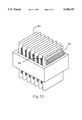
- FIG. 10 is a partially broken-away perspective view of a heat exchanger and surrounding framework in accordance with a third embodiment of the invention.
- FIG. 1 illustrates an air exchanger 10 in accordance with a preferred embodiment of the present invention.
- the air exchanger comprises a rectangular-shaped outer housing including a front wall 11, sidewalls 12 and 13, rear wall 14, top wall 15 and bottom wall 16.
- An insulating layer 17 (see FIG. 5) composed of a foam material is preferably provided to reduce heat transfer through the walls and to acoustically insulate the air exchanger so that it operates quietly.
- the insulating layer may be located within the walls of the housing, or it may be proximate to or contacting its interior surface.
- the air exchanger 10 has a compact size so that it can be placed in a conventional window.
- the front wall 11 is positioned so that it faces the interior of the room. It includes a front air inlet 18 through which indoor air is drawn into the air exchanger.
- the illustrated front air inlet is closed by a protective grille 19.
- the grille prevents any direct access to an exhaust fan 20 which draws air from the room and through the air exchanger.
- the illustrated protective grille 18 is mounted to the front wall by fasteners such as screws or the like.
- the grille may optionally be formed integrally with the front wall.
- the front wall 11 includes two pairs of front or incoming fresh air outlets 21 through which outdoor air having passed through the air exchanger enters the interior of a room.
- the front air outlets are preferably formed as louvers which direct the outdoor air into the room.
- the front air outlets are approximately equally spaced from air inlet 16 as shown in FIG. 1.
- the rear wall 14 of the housing which can be positioned outdoors of the room window, includes a rear air inlet 22 through which outdoor air is drawn into the air exchanger.
- the rear air inlet 22 preferably has the same size and structure as the front air inlet 18 and includes a grille 23 which covers and prevents access to an intake fan 24 which draws air into the inlet 22 and through the heat exchanger.
- inlet 22 is located higher above the bottom wall 16 of the housing than is front air inlet 18.
- the rear wall 14 includes two pairs of rear air outlets 21' through which indoor air having passed through the air exchanger exits to the outdoors.
- the rear air outlets preferably are louvers which direct the indoor air exiting the air exchanger outwardly of the heat exchanger.
- the rear air outlets are approximately equally spaced from the rear air inlet 22.
- the air exchanger includes vertically spaced air passages including a lower air passage 25 through which indoor air travels after entering the front air inlet 18, and an upper air passage 26 through which outdoor air travels after entering the rear air inlet 22.
- the lower air passage is formed by lower parallel vertical walls 27 which extend from the front wall 11 to the rear wall 14, bottom wall 16 and a horizontal wall 28.
- the upper air passage is formed by upper parallel vertical walls 29 which extend from the front wall 11 to the rear wall 14, top wall 15 and horizontal wall 28. The air passages are separated from each other by the horizontal wall 28 which prevents the indoor and outdoor air streams from mixing.
- the indoor and outdoor air streams traverse the lower and upper air passages, respectively, they are directed toward a pair of heat exchangers 30 and 31 for transferring heat between the indoor and outdoor air streams to either raise or lower the temperature of the outdoor air depending on the relative temperature of the indoor air stream.
- the heat exchangers are located on opposite sides of the air passages 25 and 26.
- the heat exchangers 30 and 31 each extend from the bottom wall 16 upwardly to the top wall 15 of the housing.
- the upper and lower portions of the heat exchangers are sealed in airtight relationship to the top and bottom walls, respectively, of the air exchanger.
- the sealant is preferably a liquid sealant which hardens to seal the air exchanger. The airtight seals assure that the indoor and outdoor air streams remain separated from each other as they travel through the heat exchangers.
- the heat exchangers are formed of a continuous sheet of material which is formed in a somewhat serpentine structure which defines a plurality of alternating first channels 34 and second channels 35 which are separated from each other by generally parallel walls 36.
- the structure in FIG. 3 is made up of corrugated aluminum which is shown in greater detail in FIG. 7.
- the walls 36 are as compactly spaced as possible without creating any metal-to-metal contact and are preferably generally parallel to one another.
- the first channels each open toward the front wall 11 and are closed toward the rear wall 14.
- the second channels open toward the rear wall and are closed toward the front wall.
- the heat exchangers are preferably composed of aluminum-based material having a high thermal conductivity. Although aluminum is the preferred embodiment, others materials, such as polystyrene, may be used. Both polystyrene and aluminum are also lightweight and thus contribute to the low weight of the air exchanger.
- heat exchanger 30 preferably includes a front separating framework 37, preferably formed of a lightweight material, such as foam or plastic, and having a plurality of parallel spacers 38 which extend at least partially into the first channels toward the rear wall.
- the spacers prevent the metal-to-metal contact of corrugated walls 36.
- the spacers also diffuse the air as it flows through the heat exchanger and, thus, increase the efficiency.
- Rear separating framework 39 also preferably formed of a lightweight material, has a plurality of spacers 40 which extend at least partially into the second channels toward the front wall.
- Heat exchanger 31 is similar in design to heat exchanger 30.
- FIG. 8 is an enlarged view of the encircled portion of heat exchanger 30, illustrated in FIG. 7.
- the upwardly directed arrows, I represent the flow of indoor air through the second channels 35
- downward directed arrows, O represent the flow of outdoor air through the first channels 34.
- the corrugated walls 36 provide two important functions with respect to the airflow through the heat exchangers. First, the indoor and outdoor air streams are prevented from mixing with each other. Second, the corrugated wall structure provides an increased amount of wall surface area to increase the heat exchange efficiency between the two air streams.
- a second embodiment of a heat exchanger utilizes the continuous sheet 42, illustrated in FIG. 9.
- Lines 43 illustrate the fold lines of the material which allows for the formation of first channels 34 and second channels 36.
- the material in FIG. 9 is folded in a serpentine manner similar to that of material 41 of FIG. 7.
- the material for the continuous sheet 42, in FIG. 9, is made up of pleated sections 44, 45 and 46, which are repeatedly placed in a continuous line down the entire length of corrugated material 42 with spaces left for fold lines 43 between each section of pleating.
- Pleated section 44 is offset from pleated section 45.
- Pleated section 46 is further offset from pleated section 45.
- the offset of section 45 from section 46 and section 46 from section 47 is, as shown in FIG. 9, such that the high points of the pleats of each section are not in line.
- FIG. 10 illustrates a third embodiment of heat exchanger 30 and 31.
- the continuous sheet of material 60 is now wound in a serpentine manner around spacers 61 & 62.
- Spacers 61 & 62 are made up of a lightweight material, such as polystyrene.
- Spacers 61 & 62 are corrugated to form passages such that air is forced into the heat core.
- the pleats of section 61 and 62 as shown in FIG. 10 are formed in the shape of a "C" and direct the air flow through the passages.
- To prevent intermingling of air flow the top and bottom of material 60 is sealed as described in FIG. 3.
- the air passes through the heat core, either in an upward or downward direction, and out the opposing end of the heat core.
- the air exchanger 10 further includes fans for drawing air into the air exchanger.
- the first or indoor air exhaust fan 20 is positioned within the lower air passage 25 for drawing indoor air into the air exchanger through the front air inlet 18.
- the second or outdoor air intake fan 24 is vertically spaced from the first fan and is positioned within the upper air passage 26 for drawing outdoor air into the air exchanger through the rear air inlet 22.
- the fans are preferably driven by variable speed motors 43 (see FIG. 6) which are actuated by an electrical switch 44 (see FIG. 1) located inside of the front wall.
- An on-off control knob 45 is connected to the switch and extends outward from the front wall.
- An electrical cord 46 having a room outlet plug at one end, extends from the sidewall 12 and provides power to fans 20 and 24.
- indoor air enters the air exchanger through the front air inlet 18 and is drawn through the lower air passage 25 and into the second channels 35 of the first and second heat exchangers near their bottom ends.
- the indoor air traverses the second channels in an upward direction and exits the air exchanger through the rear air outlets 21'.
- the outdoor air is drawn into the air exchanger through the rear air inlet 22 by fan 24, and travels through the upper air passage 26, and enters the first channels 34 of the first and second heat exchangers near their top ends.
- the outdoor air travels in a downward direction through the first channels and exits the air exchanger through the front air inlets 21.
- the indoor air enters and exits the second channel, adjacent to the rear wall 14, and the outdoor air enters and exits the first channels adjacent to the front wall.
- the air exchanger preferably includes means for regulating airflow through the heat exchangers.
- the regulating means includes a front baffle 47 and a rear baffle 48 associated with the first heat exchanger 30, and a front baffle 49 and a rear baffle 50 associated with the second heat exchanger 31.
- the front baffles regulate the flow of outdoor air through the first channels 34
- the rear baffles regulate the flow of indoor air through the second channels 35.
- the baffles taper along their length to thereby define open air headers or channels which decrease in cross-section or volume along their length and which function to distribute air into the heat exchangers.
- the structure of the rear baffles 48 and 50 is illustrated in FIG. 3.
- the header space 51 is generally triangular-shaped and opens into the second channels near the bottom ends thereof.
- Indoor air flows from the lower air passage 25 to the second channels by passing through the hollow interior header defined by the rear baffles.
- the cross-sectional flow areas of the rear header decreases in the directions from the lower air passage toward the sidewalls 12 and 13. Accordingly, the air initially enters the largest volume of the header, and the indoor air enters the second channels located closest to the vertical walls 26 of the lower air passage.
- the volume of the header decreases along its length to compensate for air progressively entering the second channels as the air fills the header space. This more uniformly distributes the airflow along the entire length of the heat exchanger. Consequently, airflow through the heat exchangers is uniform, and airflow resistance which would cause wear on the fan 24 is reduced.
- FIG. 4 illustrates the front baffles 47 and 49 which regulate the flow of outdoor air, "O", into the first channels 34 near their upper ends.
- the front baffles also define open tapering headers 52 having a generally triangular shape. Outdoor air flows through the upper passage 26 and then travels upwardly along the inclined baffles. The air then enters the top portion of the first channels through the air inlet portions 53 located between the surface 54 and the top wall 15. The air initially enters the largest volume of the header and enters the air inlet portions closest to the vertical walls 29 of the upper air passage 26.
- the header volume decreases as previously discussed to create a more uniform flow of air through the heat exchangers and reduces wear on the second fan 24.
- FIGS. 5 and 6 further illustrate the pattern of flow of outdoor air through the heat exchangers 30 and 31 and into the indoors by way of the front air outlets 21.
- the air exchanger continuously exchanges the indoor and outdoor air and, at the same time, does not significantly affect the indoor air temperature.
- the outdoor air is either heated or cooled as it passes through the heat exchangers, depending on the relative temperature of the indoor air traveling in a counter-direction.
- the heat transfer efficiency, E may be defined as follows:
- T o is the outdoor temperature
- T e is the temperature of the outdoor air as it enters the indoors
- T i is the indoor temperature.
- T o the efficiency of the heat exchangers
- the outdoor temperature is 80° F.
- the indoor temperature is 60° F.
- T e will equal 70° F.
- T e will more closely approach the indoor temperature as the efficiency increases and, at a theoretical maximum efficiency of 1.0, these two temperatures will be equal.
- T o 60° F.
- T i 80° F. and an efficiency of 0.5
- T e 70° F.
- the heat exchange means in accordance with the present invention, has a high efficiency such that the temperature of the outdoor air entering the room approaches the indoor temperature as closely as possible.
- the efficiency is from about 0.5 to about 0.8 so that the temperature difference between the outdoor air that enters the room and the indoors will be minimized. This is especially important when the temperature difference between the indoors and outdoors is greatest during the coldest months of the year.
Abstract
Description
E=(T.sub.o -T.sub.e)/(T.sub.o -T.sub.i)
E=(T.sub.i -T.sub.e)/(T.sub.i -T.sub.o)
Claims (15)
Priority Applications (1)
| Application Number | Priority Date | Filing Date | Title |
|---|---|---|---|
| US08/160,523 US5458187A (en) | 1993-12-01 | 1993-12-01 | Dual core air-to-air heat exchanger |
Applications Claiming Priority (1)
| Application Number | Priority Date | Filing Date | Title |
|---|---|---|---|
| US08/160,523 US5458187A (en) | 1993-12-01 | 1993-12-01 | Dual core air-to-air heat exchanger |
Publications (1)
| Publication Number | Publication Date |
|---|---|
| US5458187A true US5458187A (en) | 1995-10-17 |
Family
ID=22577233
Family Applications (1)
| Application Number | Title | Priority Date | Filing Date |
|---|---|---|---|
| US08/160,523 Expired - Lifetime US5458187A (en) | 1993-12-01 | 1993-12-01 | Dual core air-to-air heat exchanger |
Country Status (1)
| Country | Link |
|---|---|
| US (1) | US5458187A (en) |
Cited By (17)
| Publication number | Priority date | Publication date | Assignee | Title |
|---|---|---|---|---|
| EP0777094A3 (en) * | 1995-11-29 | 1998-11-25 | Mitsubishi Denki Kabushiki Kaisha | Heat exchanging element |
| US6612365B1 (en) * | 1999-09-17 | 2003-09-02 | Matsushita Electric Industrial Co., Ltd. | Heating-element accommodating-box cooling apparatus and method of controlling the same |
| US20040226702A1 (en) * | 2000-11-27 | 2004-11-18 | Theodor Johannes Peter Toonen | Heat exchanger |
| US20050217836A1 (en) * | 2004-03-30 | 2005-10-06 | Whittenberger William A | Heat exchanger for high-temperature applications |
| WO2006008184A1 (en) * | 2004-07-23 | 2006-01-26 | Oxycell Holding B.V. | Folded heat exchanger |
| US20080222932A1 (en) * | 2007-03-09 | 2008-09-18 | Peng Yun | Display cabinet for light emitting diode lights and method of use |
| US20100186927A1 (en) * | 2006-05-04 | 2010-07-29 | John Gietzen | Thermal energy exchanger |
| US20110146952A1 (en) * | 2007-08-17 | 2011-06-23 | Grundfos Management A/S | A heat exchanger |
| US20130281001A1 (en) * | 2010-12-20 | 2013-10-24 | Daikin Industries, Ltd. | Ventilation device |
| CN104697134A (en) * | 2015-03-26 | 2015-06-10 | 安徽悦达环保科技有限公司 | Heat exchanger for ventilator |
| WO2016069355A3 (en) * | 2014-10-27 | 2016-06-23 | Ebullient, Llc | Heat exchanger with interconnected fluid transfer members |
| US20170138639A1 (en) * | 2007-06-27 | 2017-05-18 | Racool, L.L.C. | Building Designs and Heating and Cooling Systems |
| US9964338B2 (en) | 2007-06-27 | 2018-05-08 | Racool, L.L.C. | Building designs and heating and cooling systems |
| US10260422B2 (en) | 2016-05-06 | 2019-04-16 | United Technologies Corporation | Heat temperature gradient heat exchanger |
| US10809007B2 (en) * | 2017-11-17 | 2020-10-20 | General Electric Company | Contoured wall heat exchanger |
| US10866014B2 (en) | 2007-06-27 | 2020-12-15 | Racool, L.L.C. | Building designs and heating and cooling systems |
| US11906218B2 (en) | 2014-10-27 | 2024-02-20 | Ebullient, Inc. | Redundant heat sink module |
Citations (15)
| Publication number | Priority date | Publication date | Assignee | Title |
|---|---|---|---|---|
| US850784A (en) * | 1906-09-13 | 1907-04-16 | Harold S Richmond | Ventilating apparatus. |
| US2092835A (en) * | 1936-07-07 | 1937-09-14 | Kenneth P Edwards | Heat exchange device |
| GB647699A (en) * | 1948-06-23 | 1950-12-20 | English Electric Co Ltd | Improvements in and relating to plate type heat exchangers |
| US2945680A (en) * | 1955-04-28 | 1960-07-19 | Chrysler Corp | Heat exchanger |
| FR1592524A (en) * | 1968-05-30 | 1970-05-19 | ||
| US3640340A (en) * | 1970-11-20 | 1972-02-08 | Baxter Laboratories Inc | Heat exchange device with convoluted heat transfer wall |
| US4040804A (en) * | 1975-05-23 | 1977-08-09 | Halm Instrument Co., Inc. | Heat and moisture exchanger |
| US4042018A (en) * | 1975-09-29 | 1977-08-16 | Des Champs Laboratories Incorporated | Packaging for heat exchangers |
| DE2947432A1 (en) * | 1979-11-24 | 1981-05-27 | Uwe 7210 Rottweil Klix | Air-to-air heat exchanger - comprises flat heat conductive elements between fresh and stale air passages |
| WO1981002060A1 (en) * | 1980-01-14 | 1981-07-23 | Caterpillar Tractor Co | Low stress heat exchanger and method of making the same |
| JPS5749793A (en) * | 1980-09-10 | 1982-03-23 | Toshiba Corp | Heat exchanger |
| US4497362A (en) * | 1983-03-21 | 1985-02-05 | Southern California Gas Co. | Regenerative room air exchanger |
| DE3327685A1 (en) * | 1983-08-01 | 1985-02-21 | Karlheinz Dipl.-Phys. Dr. 3300 Braunschweig Raetz | Ventilator with heat recovery |
| DE3514474A1 (en) * | 1985-04-22 | 1986-10-23 | Klöckner-Humboldt-Deutz AG, 5000 Köln | Heat exchanger which operates according to the counterflow principle and only has one terminating box |
| US5238052A (en) * | 1989-08-17 | 1993-08-24 | Stirling Technology, Inc. | Air to air recouperator |
-
1993
- 1993-12-01 US US08/160,523 patent/US5458187A/en not_active Expired - Lifetime
Patent Citations (15)
| Publication number | Priority date | Publication date | Assignee | Title |
|---|---|---|---|---|
| US850784A (en) * | 1906-09-13 | 1907-04-16 | Harold S Richmond | Ventilating apparatus. |
| US2092835A (en) * | 1936-07-07 | 1937-09-14 | Kenneth P Edwards | Heat exchange device |
| GB647699A (en) * | 1948-06-23 | 1950-12-20 | English Electric Co Ltd | Improvements in and relating to plate type heat exchangers |
| US2945680A (en) * | 1955-04-28 | 1960-07-19 | Chrysler Corp | Heat exchanger |
| FR1592524A (en) * | 1968-05-30 | 1970-05-19 | ||
| US3640340A (en) * | 1970-11-20 | 1972-02-08 | Baxter Laboratories Inc | Heat exchange device with convoluted heat transfer wall |
| US4040804A (en) * | 1975-05-23 | 1977-08-09 | Halm Instrument Co., Inc. | Heat and moisture exchanger |
| US4042018A (en) * | 1975-09-29 | 1977-08-16 | Des Champs Laboratories Incorporated | Packaging for heat exchangers |
| DE2947432A1 (en) * | 1979-11-24 | 1981-05-27 | Uwe 7210 Rottweil Klix | Air-to-air heat exchanger - comprises flat heat conductive elements between fresh and stale air passages |
| WO1981002060A1 (en) * | 1980-01-14 | 1981-07-23 | Caterpillar Tractor Co | Low stress heat exchanger and method of making the same |
| JPS5749793A (en) * | 1980-09-10 | 1982-03-23 | Toshiba Corp | Heat exchanger |
| US4497362A (en) * | 1983-03-21 | 1985-02-05 | Southern California Gas Co. | Regenerative room air exchanger |
| DE3327685A1 (en) * | 1983-08-01 | 1985-02-21 | Karlheinz Dipl.-Phys. Dr. 3300 Braunschweig Raetz | Ventilator with heat recovery |
| DE3514474A1 (en) * | 1985-04-22 | 1986-10-23 | Klöckner-Humboldt-Deutz AG, 5000 Köln | Heat exchanger which operates according to the counterflow principle and only has one terminating box |
| US5238052A (en) * | 1989-08-17 | 1993-08-24 | Stirling Technology, Inc. | Air to air recouperator |
Non-Patent Citations (4)
| Title |
|---|
| "Z Duct Energy Recovery Unit" publication of Deschamps Energy Labs Inc, East Hanover N.J., (Mar. 1975). |
| Air to Air Heat Exchangers Directory & Buyer s Guide, Cutler Information Corp., 1987. * |
| Air-to-Air Heat Exchangers Directory & Buyer's Guide, Cutler Information Corp., 1987. |
| Z Duct Energy Recovery Unit publication of Deschamps Energy Labs Inc, East Hanover N.J., (Mar. 1975). * |
Cited By (27)
| Publication number | Priority date | Publication date | Assignee | Title |
|---|---|---|---|---|
| EP0777094A3 (en) * | 1995-11-29 | 1998-11-25 | Mitsubishi Denki Kabushiki Kaisha | Heat exchanging element |
| US6612365B1 (en) * | 1999-09-17 | 2003-09-02 | Matsushita Electric Industrial Co., Ltd. | Heating-element accommodating-box cooling apparatus and method of controlling the same |
| US7131288B2 (en) * | 2000-11-27 | 2006-11-07 | Inco Limited | Heat exchanger |
| US20040226702A1 (en) * | 2000-11-27 | 2004-11-18 | Theodor Johannes Peter Toonen | Heat exchanger |
| WO2005103596A3 (en) * | 2004-03-30 | 2006-09-28 | Catacel Corp | Heat exchanger for high-temperature applications |
| WO2005103596A2 (en) * | 2004-03-30 | 2005-11-03 | Catacel Corporation | Heat exchanger for high-temperature applications |
| US7150099B2 (en) * | 2004-03-30 | 2006-12-19 | Catacel Corp. | Heat exchanger for high-temperature applications |
| US20050217836A1 (en) * | 2004-03-30 | 2005-10-06 | Whittenberger William A | Heat exchanger for high-temperature applications |
| WO2006008184A1 (en) * | 2004-07-23 | 2006-01-26 | Oxycell Holding B.V. | Folded heat exchanger |
| US20080156467A1 (en) * | 2004-07-23 | 2008-07-03 | Reinders Johannes Antonius Mar | Folded Heat Exchanger |
| US8256497B2 (en) | 2006-05-04 | 2012-09-04 | John Gietzen | Thermal energy exchanger |
| US20100186927A1 (en) * | 2006-05-04 | 2010-07-29 | John Gietzen | Thermal energy exchanger |
| US20080222932A1 (en) * | 2007-03-09 | 2008-09-18 | Peng Yun | Display cabinet for light emitting diode lights and method of use |
| US20170138639A1 (en) * | 2007-06-27 | 2017-05-18 | Racool, L.L.C. | Building Designs and Heating and Cooling Systems |
| US10866014B2 (en) | 2007-06-27 | 2020-12-15 | Racool, L.L.C. | Building designs and heating and cooling systems |
| US10082317B2 (en) * | 2007-06-27 | 2018-09-25 | Racool, L.L.C. | Building designs and heating and cooling systems |
| US9964338B2 (en) | 2007-06-27 | 2018-05-08 | Racool, L.L.C. | Building designs and heating and cooling systems |
| US20110146952A1 (en) * | 2007-08-17 | 2011-06-23 | Grundfos Management A/S | A heat exchanger |
| US20130281001A1 (en) * | 2010-12-20 | 2013-10-24 | Daikin Industries, Ltd. | Ventilation device |
| US8899309B2 (en) * | 2010-12-20 | 2014-12-02 | Daikin Industries, Ltd. | Ventilation device |
| US9891002B2 (en) | 2014-10-27 | 2018-02-13 | Ebullient, Llc | Heat exchanger with interconnected fluid transfer members |
| WO2016069355A3 (en) * | 2014-10-27 | 2016-06-23 | Ebullient, Llc | Heat exchanger with interconnected fluid transfer members |
| US11906218B2 (en) | 2014-10-27 | 2024-02-20 | Ebullient, Inc. | Redundant heat sink module |
| CN104697134B (en) * | 2015-03-26 | 2017-11-21 | 安徽悦达环保科技有限公司 | A kind of heat exchanger for ventilator |
| CN104697134A (en) * | 2015-03-26 | 2015-06-10 | 安徽悦达环保科技有限公司 | Heat exchanger for ventilator |
| US10260422B2 (en) | 2016-05-06 | 2019-04-16 | United Technologies Corporation | Heat temperature gradient heat exchanger |
| US10809007B2 (en) * | 2017-11-17 | 2020-10-20 | General Electric Company | Contoured wall heat exchanger |
Similar Documents
| Publication | Publication Date | Title |
|---|---|---|
| US5458187A (en) | Dual core air-to-air heat exchanger | |
| US5497823A (en) | Energy recovery ventilator: means for defrosting heat exchanger medium and damper motor actuation means | |
| KR101133044B1 (en) | Ventilation system having heat exchanger | |
| JPH0216211Y2 (en) | ||
| US5431215A (en) | Pressure switch for energy recovery ventilator | |
| CA2047396C (en) | Double-walled cabinet structure for air conditioning equipment | |
| US4874042A (en) | Corrugated cardboard heat exchanger | |
| KR101251221B1 (en) | Window ventilation system | |
| US4290247A (en) | Fluid flow insulation system | |
| HU217496B (en) | Method and apparatus for the heating and cooling of buildings and heat insulating wall covering | |
| JPS5974443A (en) | Ventilating apparatus for building | |
| KR900003868Y1 (en) | Air conditioner system for building | |
| KR100975102B1 (en) | The heat exchanger for the ventilation system | |
| US7028752B2 (en) | Ventilation device | |
| KR102173317B1 (en) | Heat recovery ventilation apparatus and heat recovery ventilation system using the apparatus | |
| FI74110B (en) | ANORDNING VID FOENSTER. | |
| JPH0141065Y2 (en) | ||
| KR101431211B1 (en) | Electrical Heating Element Using Counterflow Ventilation Unit | |
| WO1996035083A1 (en) | Heat exchange unit and methods | |
| EP0259339B1 (en) | Method for arranging of ventilation of building and structure for applying of the method | |
| CN2771718Y (en) | Self-decorative multi-path multi function upgradable ventilation pipeline | |
| KR100627878B1 (en) | Energy recovery ventilator for window | |
| JPH0218415Y2 (en) | ||
| CN212362238U (en) | Vertical fresh air conditioning equipment | |
| CN217329942U (en) | Assembled solar room temperature adjusting system matched in all seasons |
Legal Events
| Date | Code | Title | Description |
|---|---|---|---|
| AS | Assignment |
Owner name: HONEYWELL INC., MINNESOTA Free format text: ASSIGNMENT OF ASSIGNORS INTEREST;ASSIGNOR:DAVIS, GEORGE B.;REEL/FRAME:006787/0639 Effective date: 19931130 |
|
| FEPP | Fee payment procedure |
Free format text: PAYOR NUMBER ASSIGNED (ORIGINAL EVENT CODE: ASPN); ENTITY STATUS OF PATENT OWNER: LARGE ENTITY |
|
| STCF | Information on status: patent grant |
Free format text: PATENTED CASE |
|
| FEPP | Fee payment procedure |
Free format text: PAYOR NUMBER ASSIGNED (ORIGINAL EVENT CODE: ASPN); ENTITY STATUS OF PATENT OWNER: LARGE ENTITY Free format text: PAYER NUMBER DE-ASSIGNED (ORIGINAL EVENT CODE: RMPN); ENTITY STATUS OF PATENT OWNER: LARGE ENTITY |
|
| FPAY | Fee payment |
Year of fee payment: 4 |
|
| FEPP | Fee payment procedure |
Free format text: PAYER NUMBER DE-ASSIGNED (ORIGINAL EVENT CODE: RMPN); ENTITY STATUS OF PATENT OWNER: LARGE ENTITY Free format text: PAYOR NUMBER ASSIGNED (ORIGINAL EVENT CODE: ASPN); ENTITY STATUS OF PATENT OWNER: LARGE ENTITY |
|
| FPAY | Fee payment |
Year of fee payment: 8 |
|
| FPAY | Fee payment |
Year of fee payment: 12 |