US5458284A - Single-part statement mailer with charge card - Google Patents
Single-part statement mailer with charge card Download PDFInfo
- Publication number
- US5458284A US5458284A US08/332,370 US33237094A US5458284A US 5458284 A US5458284 A US 5458284A US 33237094 A US33237094 A US 33237094A US 5458284 A US5458284 A US 5458284A
- Authority
- US
- United States
- Prior art keywords
- panels
- panel
- mailer
- ply
- marginal
- Prior art date
- Legal status (The legal status is an assumption and is not a legal conclusion. Google has not performed a legal analysis and makes no representation as to the accuracy of the status listed.)
- Expired - Fee Related
Links
- 239000000853 adhesive Substances 0.000 claims description 75
- 230000001070 adhesive effect Effects 0.000 claims description 75
- 239000003292 glue Substances 0.000 abstract description 68
- 238000005520 cutting process Methods 0.000 abstract description 4
- 239000004831 Hot glue Substances 0.000 description 14
- 238000000034 method Methods 0.000 description 10
- 239000000463 material Substances 0.000 description 6
- 238000004026 adhesive bonding Methods 0.000 description 5
- 230000015572 biosynthetic process Effects 0.000 description 5
- 238000004891 communication Methods 0.000 description 5
- 238000004519 manufacturing process Methods 0.000 description 4
- 238000007789 sealing Methods 0.000 description 4
- 238000003384 imaging method Methods 0.000 description 3
- 239000000758 substrate Substances 0.000 description 3
- 230000005587 bubbling Effects 0.000 description 2
- 239000012943 hotmelt Substances 0.000 description 2
- KVWDHTXUZHCGIO-UHFFFAOYSA-N olanzapine Chemical compound C1CN(C)CCN1C1=NC2=CC=CC=C2NC2=C1C=C(C)S2 KVWDHTXUZHCGIO-UHFFFAOYSA-N 0.000 description 2
- 238000012545 processing Methods 0.000 description 2
- 238000012795 verification Methods 0.000 description 2
- 230000004075 alteration Effects 0.000 description 1
- 230000007423 decrease Effects 0.000 description 1
- 230000003247 decreasing effect Effects 0.000 description 1
- 238000001514 detection method Methods 0.000 description 1
- 238000009826 distribution Methods 0.000 description 1
- 230000000694 effects Effects 0.000 description 1
- 238000000605 extraction Methods 0.000 description 1
- -1 for example Substances 0.000 description 1
- 238000012986 modification Methods 0.000 description 1
- 230000004048 modification Effects 0.000 description 1
- 238000009877 rendering Methods 0.000 description 1
- 238000012552 review Methods 0.000 description 1
Images


Classifications
-
- B—PERFORMING OPERATIONS; TRANSPORTING
- B65—CONVEYING; PACKING; STORING; HANDLING THIN OR FILAMENTARY MATERIAL
- B65D—CONTAINERS FOR STORAGE OR TRANSPORT OF ARTICLES OR MATERIALS, e.g. BAGS, BARRELS, BOTTLES, BOXES, CANS, CARTONS, CRATES, DRUMS, JARS, TANKS, HOPPERS, FORWARDING CONTAINERS; ACCESSORIES, CLOSURES, OR FITTINGS THEREFOR; PACKAGING ELEMENTS; PACKAGES
- B65D27/00—Envelopes or like essentially-rectangular containers for postal or other purposes having no structural provision for thickness of contents
- B65D27/06—Envelopes or like essentially-rectangular containers for postal or other purposes having no structural provision for thickness of contents with provisions for repeated re-use
-
- Y—GENERAL TAGGING OF NEW TECHNOLOGICAL DEVELOPMENTS; GENERAL TAGGING OF CROSS-SECTIONAL TECHNOLOGIES SPANNING OVER SEVERAL SECTIONS OF THE IPC; TECHNICAL SUBJECTS COVERED BY FORMER USPC CROSS-REFERENCE ART COLLECTIONS [XRACs] AND DIGESTS
- Y10—TECHNICAL SUBJECTS COVERED BY FORMER USPC
- Y10S—TECHNICAL SUBJECTS COVERED BY FORMER USPC CROSS-REFERENCE ART COLLECTIONS [XRACs] AND DIGESTS
- Y10S229/00—Envelopes, wrappers, and paperboard boxes
- Y10S229/922—Envelopes, wrappers, and paperboard boxes with decorative feature
- Y10S229/923—Gift wrapped
Definitions
- the present invention relates to a single-part statement formed of a single ply folded to form panels which are adhered together to form a mailer, including a business return envelope, a payment coupon and a statement, as well as to methods for forming such mailer.
- the present invention also relates to a mailer having one or more charge cards attached to a panel of the mailer and which mailer minimizes the possibility of detecting the presence of the charge cards and reduces the occurrence of theft and fraud in connection with forwarding charge cards through the mails.
- Statements for example, credit card statements, as well as other types of business forms, are typically produced by printing a statement and inserting the statement, together with a separate return envelope and any inserts, into an outgoing envelope.
- Personalized information is normally printed on the statement, such as account numbers, payments due, etc., and on the outgoing envelope. Portions of all three parts are also printed with non-personalized generic information, such as advertising information, the name and address of the company forwarding the statement, identifiers for the personalized information and other information.
- a card issuer typically mails the reissued charge card or cards to the individual cardholder. This typically takes the form of a mailing separate and apart from the usual monthly communications between the card issuer and the cardholder, thus constituting an additional cost. Still further, by using a separate mailing, the cards are normally readily recognizable in the mail as charge cards, even with efforts to disguise the contents of the communication, because the card or cards are relatively easy to feel in the envelope. Consequently, many charge cards are stolen from the mail stream.
- a single-paper ply in web form is divided into a series of panels and foldlines.
- the web is then folded and the panels adhered to one another by adhesive in alternating steps.
- adhesive is applied to one or both (depending upon the nature of the adhesive) of first and second panels which will form a return envelope in each mailer.
- the continuous ply is subsequently folded to register and adhere those panels to one another, thus forming the return envelope.
- adhesive is applied to one or both of the second and fifth panels, with the ply being subsequently folded to register and adhere the second and fifth panels one to the other.
- Adhesive is then applied to the first and fourth panels. Subsequently, the ply is folded about registering fourth and third foldlines to register the third and fourth panels with the first, second and fifth panels and adhere the first and fourth panels to one another. Adhesive is then applied to the fourth and sixth panels whereupon they are subsequently folded about a fifth foldline and adhered to one another, completing the mailer.
- the first and second panels are folded to form the return envelope similarly as described above in connection with the first embodiment.
- the margins of the first and second panels are die-cut substantially parallel to or slightly inset from the locations of the lines of perforations which will form the tear strips in other panels of the complete mailer.
- the next or second foldline is located between the return envelope flap and the top of the first panel.
- the registering first and second panels are folded about the second foldline into registration with the third panel, i.e., the payment coupon.
- first, second, third and seventh panels are either parallel with or inset from the lines of perforations forming the tear strips in the completed mailer.
- the registering first, second, third and seventh panels are then folded over a third foldline to overlie the fourth panel
- Adhesive is then applied to one of the fourth and fifth panels in the margins thereof to secure the fourth and fifth panels to one another when the first through fourth and seventh panels are folded about a fourth foldline into registration with the fifth panel.
- Adhesive is then applied to the margins of the fourth or sixth panel and the panels folded about a fifth foldline to form the completed mailer.
- the edges of the return envelope do not carry tear strips and that they are perfectly formed in the production of the mailer.
- frayed or ragged edges resulting from inadequate tearing of the tear strips by the recipient of the mailer are avoided, thereby facilitating alignment of the return envelope in automatic mail opening machinery.
- a scoreline about which the return envelope flap may be folded. This avoids skewing of the flap during sealing and facilitates proper sealing thereby also affording proper alignment of the return envelope in the automatic mail opening machinery.
- the adhesive is preferably a cold glue applied in spots to one of the panels to be adhered together, although it will be appreciated that other types of adhesive, for example, hot melts, and other types of adhesive configurations, such as continuous lines of glue, may be used.
- the adhesive is applied, preferably in spots, to the continuous web in areas of the panels which will form end tear strips for the outgoing mailer in final assembly.
- loose inserts having both personalized and non-personalized information may be inserted into the mailer during its formation as described above.
- loose inserts may be disposed on top of the first panel after the panels are folded about its second foldline. The subsequent foldlines and adhesive applications are such as to maintain the inserts within the mailer after final assembly.
- fugitive glue lines or dots of adhesive are provided between the panels forming the return envelope. These are preferably provided adjacent to the bottom of the envelope, and inset from the marginal lines of adhesive forming the side edges of the return envelope.
- the various forms of mailers described above may also be used for the distribution of charge cards. That is, because many documents received by charge card members are mailed on a regular cycle, for example, monthly statements, reissued charge cards may be placed directly in the monthly statement, i.e., the mailers described above, in accordance with a still further aspect of the present invention. Thus, one or more charge cards may be placed directly on one of the panels of the above-described mailers and verified for accurate placement. The mailer web may then be folded about the card(s) and either self-sealed or inserted into a standard envelope.
- the thickness of the mailer facilitates concealment or non-detection of the charge card within the mailer. Also, because the card is wholly encapsulated within the mailer, any tampering with the mailer in efforts to remove the cards would be readily recognized. This is particularly true because the marginal tear strips would have to be removed to gain access to the interior of the mailer and particularly the cards.
- the charge cards may be mailed in a monthly statement, not only are the number of communications between the card issuer and cardholder decreased, but the time between the expected receipt of the monthly statement and the failure of the cardholder to receive the statement including the charge card(s) decreases the time for notification of the failure to receive the monthly statement, i.e., the bank cards.
- Card members typically expect to receive monthly statements but may not be readily cognizant that a new card is about to be issued as their present card is nearing its expiration date.
- the combined statement and card removes the possibility that the newly issued credit card would be discarded as "junk mail" as the recipient is not expecting the replacement card.
- each card may be stacked and fed from a separate card placer mounted above the web and directed through separate magnetic stripe verification systems.
- the web previously has received a patch of hot-melt glue within the card placement area which, when the card is placed in that area, will adhere the card to the mailer.
- the adhesive will have characteristics that allow the release of the card without leaving glue residue on the back of the card.
- the card placement is effected after the printing has been completed.
- the personalized (identification) information printed on the mailer and the information contained on the magnetic strip on the card may be verified against one another. Once verified, the card can be adhered to the mailer and the subsequent processes of applying further adhesive, locating inserts, forming perforations and the like, may then be accomplished.
- charge card is meant to include any card containing personalized information identifying a cardholder or an account typically, although not necessarily, comprising a card formed of plastic material usually embossed with account numbers or other personalized identification or a magnetic stripe containing such information.
- charge cards include bank cards, department store charge cards, credit cards such as VISA or MASTERCARD, as well as other identification cards such as cards signifying membership in organizations and not necessarily relating to financial services.
- a mailer comprising a single ply having longitudinally and transversely extending edges, first, second, third, fourth, fifth and sixth panels, and first, second, third, fourth and fifth foldlines transversely spaced one from the other and extending in a longitudinal direction, a pair of marginal lines of perforations extending transversely along the ply generally parallel to the transversely extending edges and inset therefrom, respectively, defining marginal tear strips for the mailer in the first, second, fifth and sixth panels and at least one of the third and fourth panels, at least one charge card releasably secured to one of the third and fourth panels, the first and second panels being folded about the first foldline to register the first and second panels with one another and the marginal tear strips thereof with one another, adhesive along at least one of the registering marginal tear strips of the first and second panels to secure the registering marginal tear strips to one another, and adhesive along at least portions of one of the first and second panels inset from the marginal lines of perforations
- a mailer comprising a single ply having longitudinally and transversely extending edges, first, second, third, fourth, fifth and sixth panels, and first, second, third, fourth and fifth foldlines transversely spaced one from the other and extending in a longitudinal direction, a pair of marginal lines of perforations extending transversely along the ply generally parallel to the transversely extending edges and inset therefrom, respectively, defining marginal tear strips for the mailer in the first, second, fifth and sixth panels, at least one charge card releasably secured to one of the third and fourth panels, the first and second panels being folded about the first foldline to register the first and second panels with one another and the marginal tear strips thereof with one another, adhesive between the registering marginal tear strips of the first and second panels to secure the registering marginal tear strips to one another, and adhesive between portions of the first and second panels inset from the marginal lines of perforations to secure the first and second panels to one another, respectively, to form a
- a mailer comprising a single ply having first, second, third, fourth, fifth and sixth panels and foldlines between adjacent panels, tear strips along a pair of opposite edges of the ply and along at least the edges of certain of the panels, at least one charge card releasably secured to one of the panels, the panels being folded about the foldlines to form a mailer with the first through sixth panels in registration with one another and at least two panels of the ply lying on opposite sides of the charge card within the folded mailer, adhesive securing the tear strips to one another sealing opposite edges of the mailer whereby the card is peripherally surrounded within the mailer by the adhesively secured opposite edges of the mailer and a pair of foldlines between one panel and a pair of panels adjacent the one panel, respectively.
- a communication package comprising a substrate having at least two panels and a foldline between the panels, the substrate having both fixed and variable printing applied thereto to create a billing statement, a charge card, means for releasably securing the charge card to one of the panels forming the substrate, the panels being folded about the foldline to register with one another, whereby the card and the billing statement are both contained in the communication package for forwarding to a recipient.
- a method for producing a mailer formed of a single ply having longitudinally and transversely extending edges, first, second, third, fourth, fifth and sixth panels, and first, second, third, fourth and fifth foldlines transversely spaced one from the other and extending in a longitudinal direction comprising the steps of providing a single ply of web material, imaging information on at least one side of the web, applying first and second transverse adhesive lines along transversely extending marginal areas of one of the first and second panels, the first adhesive line being inset from the second adhesive line, folding the first and second panels of the web into registration with one another, with the first and second transverse adhesive lines adhering the first and second panels to one another and the first lines of adhesive adhering the first and second panels to one another to form a return envelope, subsequently applying transverse adhesive lines along marginal areas of one of the second and fifth panels, respectively, folding the first and second panels and the fifth panel into registration with one another, and folding the third panel and the
- a method for producing a mailer formed of a single ply having longitudinally and transversely extending edges, first, second, third, fourth, fifth and sixth panels, and first, second, third, fourth and fifth foldlines transversely spaced one from the other and extending in a longitudinal direction comprising the steps of providing a single ply of web material, imaging information on at least one side of the web, forming transversely extending edges along the first, second and third panels inset from the transversely extending edges of the fourth, fifth and sixth panels, applying transverse adhesive lines along transversely extending marginal areas of the first and second panels of the web, folding the first and second panels of the web about a first foldline into registration with one another, with the transverse adhesive lines adhering the first and second panels to one another to form a return envelope, forming a return envelope flap in the third panel, folding the first and second panels and the third panel of the web into registration with one another about a second foldline between the
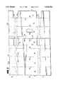
- FIG. 1 is a plan view of a portion of a web illustrating a single-part statement mailer and portions of adjoining mailers as part of the web, with foldlines and lines of perforation superposed onto the web to illustrate their respective locations, all in accordance with the present invention
- FIG. 2 is a view similar to FIG. 1 illustrating a first application of adhesive to the web
- FIG. 3 is a perspective view of the web being folded about a first foldline to form a return envelope for each mailer in the web;
- FIG. 4 is a view similar to FIG. 1, with the return envelope formed and additional adhesive lines applied to the web;
- FIG. 5 is a view of the web of FIG. 4, with the panels folded about a second foldline;
- FIG. 6 is a view similar to FIG. 5 illustrating the panels folded about registering third and fourth foldlines and with additional adhesive lines applied subsequent thereto;
- FIG. 7 is a perspective view of the sixth panel being folded about the fifth foldline and into registration with the registering first through fifth panels;
- FIG. 8 illustrates the web being severed along transverse cutlines to form the discrete mailers hereof
- FIG. 9 is a front elevational view of the return envelope, with the outer dashed lines illustrating potential cutlines for automatic mail openers and the interior dashed lines illustrating the insert within the return envelope;
- FIG. 10 illustrates a return envelope cut by an automatic mail opener with the envelope sides separated, exposing the insert for removal
- FIG. 11 is an enlarged schematic cross-sectional view taken along a line 11--11 in FIG. 8 and extending in the direction of web travel illustrating the various adhesive attachments between the tear strips of the various panels;
- FIG. 12 is a diagrammatic illustration of a method of forming the mailer hereof.
- FIG. 13 is a view similar to FIG. 1 illustrating a further embodiment of a single-part statement mailer according to the present invention
- FIG. 14 is a perspective view of the embodiment of FIG. 13 illustrating the return envelope fully formed, with the tear strips removed, and being folded over onto the next-adjacent panel;
- FIG. 15 is a view similar to FIG. 14 illustrating a further folding of the web
- FIG. 16 is a view similar to FIG. 15 illustrating the application of additional glue spots and the registering panels being folded over a further foldline;
- FIG. 17 is a perspective view illustrating the final application of glue and folding of the mailer to form the complete mailer of the embodiment of FIG. 13 hereof;
- FIG. 18 is a view similar to FIG. 1 illustrating a single-part mailer containing charge cards for inclusion within the mailer, the mailer also optionally including statement information;
- FIG. 19 is a schematic illustration of a process for forming the one-part statement mailer with one or more charge cards contained within the mailer.
- FIG. 20 is a schematic illustration of a card placer and verifier module for use with the present invention.
- each mailer prior to folding and gluing, comprises a single laid-out flat sheet which includes transversely and longitudinally extending edges 3 and 5, respectively, relative to the direction of web travel. Edges 3 extend in the transverse direction a distance greater than longitudinal edges 5 extend in the longitudinal direction.
- each mailer is die-cut, printed, folded, glued, perforated and severed along cutlines C.L. to form discrete mailers. It will be appreciated in FIG.
- dashed lines extending in the transverse direction illustrate various perforation lines applied to the mailer, as will become clear, subsequent to its folding about foldlines illustrated by the dot-dashed lines extending in the longitudinal direction, i.e., the direction of web travel.
- the longitudinally extending dashed lines represent lines of perforations formed in the web prior to any folding.
- the web W comprises a continuous single ply of paper from which is formed a plurality of mailers M, a portion of an adjacent leading mailer M1 in the direction of web travel and a portion of a trailing mailer M2 in the direction opposite the direction of web travel being illustrated in FIG. 1.
- Each mailer is divided into a plurality of panels.
- the first, second, third, fourth, fifth, sixth and seventh panels are designated 11, 12, 13, 14, 15, 16 and 17, respectively.
- the single ply forming mailer M will be folded about first, second, third, fourth, fifth and sixth foldlines which, for clarity of the following description, are designated 21, 22, 23, 24, 25 and 26, respectively.
- the panels either singly or in combination, form portions of a return envelope, a forwarding mailing envelope, a statement and a return payment coupon.
- the mailer has preprinted information on one or both sides and on one or more of the panels.
- the preprinted information can be information of a non-personalized general or generic nature applicable to all recipients of the mailer, as well as intelligent or personalized information which may be computer-generated and contain information specific to a particular addressee.
- the present single-part statement may be used as a bank credit card statement.
- the return envelope which comprises panels 11 and 12 in mailer M, may have information common to the entire mailing by the issuer of the credit card statement.
- the return address of the sender, as well as other information informing the user how to use the envelope, as well as postal bar code areas, stamp areas, and return address areas may be preprinted on and common of panels 11 and 12.
- the account statement itself which may comprise combined areas of panels 14, 15 and 16, as well as a portion of panel 13, may have both non-personalized and personalized intelligent computer-generated information.
- the non-personalized information may include standard identifiers for the personalized intelligent information, such as an account number, payment due date, total credit line, cash advance limit, new balance, available credit line, available cash limit, sales date, posting date, reference number, activity since last statement, amount, account summaries and other items which would be common to all account statements.
- these account statement areas of panels 14, 15 and 16 and 13 may also include personalized intelligent information specific to that account, for example, the actual posting date, the identity of the retailer through which the charge was incurred, the actual amount, the actual interest amount, finance charges, charges to date and other information specific to that account.
- such intelligent information is printed on the side of the single ply which will be sealed within the mailer, ensuring the privacy of the information, i.e., the side of the ply facing upwardly in FIG. 1.
- a portion of the panels, for example, panel 14, may comprise marketing or advertising materials and this likewise can be either non-personalized generic information for all addressees or personalized intelligent information based on computerized information concerning the specific addressee. i.e., the account holder.
- a payment coupon may also form part of the mailer M.
- the inset portion of panel 13 may comprise a payment coupon having both non-personalized generic and personalized intelligent information on the coupon.
- Such generic information might include a change of address information block or a block labelled amount due.
- non-personalized information which can be printed on one or both sides of the single ply and in the various panels will readily be apparent to those skilled in the art, particularly by reference to current standard account statements, payment coupons and return envelopes.
- the specific personalized intelligent information may include, for example, the account balance, minimum payment due, and due date for that particular month and statement and this likewise will be apparent to those of skill in that art.
- the opposite side of the mailer M from that illustrated in FIG. 1, may likewise contain both non-personalized generic and personalized intelligent information.
- the name and address of the recipient of the mailer may be printed on the back side of panel 15 which forms the mailing address of the outgoing mailer upon final assembly.
- Mailer opening information may be disposed on the back side of any one or more of the panels.
- the terms and conditions of the account statement may be preprinted.
- various information may be requested from the particular recipient, for example, in the event there is a disputed item on the account statement.
- the web is first longitudinally perforated at transversely spaced locations as needed for the particular statement mailer.
- lines of perforation are formed at 6 and 8 in FIG. 1 to define the payment coupon portion of panel 13 and at 9 to define a tear-off line for the return envelope bang-tail panel 17.
- the lines of perforations may be formed in the web and the web rewound in coil form for later use. Conversely, the lines of perforations may be provided as the web is removed from the coil stock prior to printing.
- the web is then printed with both the non-personalized generic and personalized intelligent information on one or both sides and in the various portions of the mailer panels, as illustrated by the various printing machines 30, 32 and 34 in FIG. 12.
- This imaging or printing may be accomplished by MIDAX print engines 30 and 32, as described in U.S. Pat. No. 5,132,713, and by a Tricon print station 34.
- the Tricon print station 34 may comprise a Tricon Ultra JetTM printer, a product of Trident, Inc. of Brookfield, Conn., identified as the Horizontal Headboard. This printer is a lightweight printer for specialized printing. It will be appreciated that the web W is taken from reel 36 and passed through the print machines to complete the printing process.
- the printed web is then turned 90° and advanced to a hot glue station 46 (FIG. 12) where hot glue or adhesive 48 is applied to the return envelope flap 46 which forms part of panel 11 directly adjacent foldline 23.
- the hot glue thus forms a rewettable adhesive for the closure flap of the return envelope.
- the web is advanced through a die-cut unit 37 where various die cuts are formed in the web. For example, and referring to FIG. 1, a die-cut window 38 for the return mailer is formed at station 37 in panel 11.
- a portion of panel 13 is die cut to form transversely extending edges 40 inset from transverse cutlines C.L., as well as inset from transversely extending perforation lines 42 later formed in the mailer after folding and gluing, as will become apparent from the ensuing description.
- panel 17 is die cut to form edges 44 inset from the corresponding lines of perforations 42.
- the die cutting about the bang-tail panel 17 and the remittance coupon portion of panel 13 cuts those portions of the mailer to an appropriate size so that neither the bang-tail nor the coupon have to be folded to be inserted into the return envelope.
- the lines of perforations form with the cutlines C.L. tear strips T.S. in the transverse margins of the completed mailer.
- the tear strips are labelled T.S. preceded by the number of the panel of which the tear strips are a part.
- the bang-tail panel is not necessary to the mailer and the mailer may be provided without such panel.
- cold glue station 50 After die-cut station 37, the web is advanced and a cold glue is applied to the web, at a subsequent cold glue station 50 by glue nozzles, to those portions of the panels which will be immediately subsequently folded and adhered to one another.
- cold glue station 50 FIG. 12
- cold glue 47 is applied in the regions of the marginal tear strips 12 T.S. of panel 12 on both sides of subsequently formed cutlines C.L.
- the cold glue is applied to areas between subsequently applied perforation lines 42 such that the cold glue lies along adjoining tear strips of adjoining mailers in the direction of web travel.
- a cold glue line 51 is additionally applied just inside the perforation lines 42 to seal the opposite end edges of panels 11 and 12 to one another when subsequently folded to form the return envelope.
- Fugitive glue spots 52 are also disposed on panels 11 and 12 inwardly of glue lines 51 and on opposite sides of foldline 21.
- the fugitive glue spots 52 extend along the edges of the return envelope from the foldline 21a limited distance, for example, less than half the height of the return envelope.
- glue line and "glue spots” are used interchangeably, it being appreciated that a continuous line of glue and spaced spots of glue may be used in the glue applications in the present invention.
- glue and glue are also used interchangeably.
- the web is plow-folded at plow-folding station 54 to fold panels 11 and 12 about foldline 21 to register panels 11 and 12 one with the other and the marginal tear strips 11 T.S. and 12 T.S. one with the other.
- the marginal tear strips of panels 11 and 12 are adhered to one another, the margins of the return envelope inside of lines of perforations 42 are adhered to one another, and interior portions of the return envelope edges adhere to one another along fugitive glue lines 52.
- These adhered fugitive glue lines form an inside guide for receiving an insert, e.g., a payment coupon and a remittance, whereby the insert is spaced from the end edges of the return envelope.
- the panel 17, if used is also folded about foldline 26 in a reverse direction to overlie the back face of panel 12 as illustrated in FIG. 3.
- web W with the return envelope formed, is then passed through a second cold glue station 58 (FIG. 12) where additional cold glue lines 59 are applied to the tear strips 12 T.S. forming part of panel 12 and a portion of the tear strip 11 T.S. of panel 11.
- Web W is advanced to a further plow-fold station 60 where the panels 13, 11 and 12 are folded about foldline 22 such that panel 13 lies in registration with panel 14 and registering panels 11 and 12 register with panel 15, as illustrated in FIG. 5. Consequently, the tear strips 15 T.S. of panel 15 adhere to the tear strips 12 T.S. of panel 12 and the portion of the tear strips 11 T.S. of panel 11 to which glue was applied.
- inserts may be disposed within the mailer in loose fashion such that when the recipient opens the mailer, the inserts fall out or can be individually removed.
- an intelligent inserter 62 (FIG. 12) is provided. Inserter 62 cooperates with the web line to provide one or more inserts 63 (FIG. 11) on the web as the web passes the discharge end of the inserter (sixteen insert stations being illustrated for inserting sixteen different types of inserts).
- the inserts may contain personalized intelligent information preprogrammed in conjunction with the printers 30, 32 and 34 such that designated inserts may be provided mailers addressed to certain addressees based on computer-generated information, e.g., demographic information. Of course, non-personalized inserts may also be inserted into the mailers as they are formed.
- the inserts, when employed in the mailer are located on top of the mailing address side of the return envelope, i.e., on top of panel 11.
- web W advances to a third cold glue station 70.
- cold glue lines 73 are applied to the portions of tear strips 14 T.S. of panel 14 exposed by the inset edges 40 of panel 13.
- Glue lines 73 also extend along overlying tear strip portions 74 of panel 13.
- the adhesive line 73 secures tear strip portions 74 of panel 13 along the tear strip 11 T.S., as well as the portions of tear strip 14 T.S. of panel 14 to the registering portion of tear strip 11 T.S. of panel 11 as illustrated in FIG. 6.
- the web is then advanced to a cold glue station 82 (FIG. 12) where cold glue lines 83 are applied along the tear strips 16 T.S. of panel 16. Additionally, cold glue is applied along the longitudinally extending edge 5 of panel 16.
- the web is then advanced to a folding station 88 where panel 16 and panels 11, 12, 13, 14 and 15, as well as panel 17 if a bang-tail panel is used, are folded into registry with one another. The glue seals the mailer along the tear strip margins.
- the web is then advanced to a perforation station 90 (FIG. 12) where the perforation lines 42 are applied along the opposite margins of the mailer inset from transverse edges 3 and through the multiple panels.
- the web is then passed through a cutoff unit 92 where the mailers are cut from the web along cutlines C.L. to form discrete mailers M.
- the web with the discrete mailers folded and glued advance in the direction of web travel, i.e., in the direction of the arrow in FIG. 8.
- the slitters slit the web along cutlines C.L., bisecting the transversely extending lines of perforations 42, forming the mailer M.
- the mailer M has marginal tear strips T.S. along its opposite ends defined by the lines of perforations 42.
- FIG. 11 is a schematic view through a mailer looking along the lines 11--11 in FIG. 8.
- the juxtaposed panels are illustrated in the order of their appearance in the mailer and the glue lines between the tear strips of the mailer are illustrated.
- the bang-tail panel 17 is disposed between panels 12 and 15 and the inserts 63 are illustrated by the dashed lines disposed between panels 11 and 13.
- the glue lines extend between the tear strips of panels 11 and 14 whereby the inserts are prevented from slipping from the mailer through the opposite ends of the mailer.
- the panel 13 is illustrated with its end edges 40 inset from the lines of perforations 42.
- the margin 74 in the background portion of the panel 13 is not illustrated.
- both marginal tear strips T.S. comprised of strips 11 T.S., 12 T.S., 13 T.S., 14 T.S., 15 T.S. and 16 T.S. at the opposite ends of the mailer may be removed along the lines of perforations 42.
- the mailer can be unfolded to a single-ply form with panels 11 and 12 remaining secured to one another by the glue lines 51 and fugitive glue lines 52 to form the return envelope.
- the account statement information may be read by the recipient from panels 16, 15 and 14, and the payment coupon in panel 13.
- the recipient may remove the account statement from the payment coupon portion of the panel 13 by detaching the account statement along longitudinally extending line of perforations 8. Additionally, the coupon statement itself may be detached from the return envelope flap along line of perforations 6. The payment coupon, because its edges 40 are inset, may be inserted into the return envelope, together with a remittance, and within the fugitive glue lines 51. The return flap is then moistened, folded over a foldline and sealed to the outer face of panel 12. If the bang-tail panel 17 forms part of the mailer, it is removed before the return envelope is sealed by tearing along the line of perforations 9.
- automatic openers may be used to remove margins of the return envelope.
- automatic slitters may slit off an eighth to a quarter inch of the top margin, as well as end margins of the return envelope, to enable suction devices to pull the panels apart, exposing the contents of the return envelope for extraction will be appreciated that the contents, including the payment coupon and payment, lie within the fugitive glue lines and thus are out of the way of the automatic mail opening cutters whereby the payment coupon and payment are free of damage and mutilation.
- FIGS. 13-17 wherein like reference numerals are applied to like parts, followed by the suffix "a", there is illustrated a mailer Ma formed of six panels 11a, 12a, 13a, 14a, 15a and 16a.
- a seventh panel 17a is also included when a bang-tail is provided the return envelope.
- adjacent mailers are shown in the web Wa, with each mailer being defined by transverse and longitudinally extending edges 3a and 5a.
- Web Wa is printed as previously described with respect to the printers 30, 32 and 34 and is also passed through the die-cut station 37 and the following hot glue station 46, where the rewettable adhesive is applied to the return envelope flap.
- the foldlines, sequence of gluing and the folding of the panels is different than in the prior embodiment, with the exception of foldlines 21 a and 26a.
- the return envelope comprised of panels 11a and 12a is formed similarly as in the previous embodiment, but with glue lines applied to one of the panels 11a and 12a only in the areas inset from the lines of perforations 42a such that, upon folding the panels 11a and 12a about foldline 21a, panels 11a and 12a form a return envelope.
- glue lines applied to one of the panels 11a and 12a only in the areas inset from the lines of perforations 42a such that, upon folding the panels 11a and 12a about foldline 21a, panels 11a and 12a form a return envelope.
- the web is passed through a cut-off station 108 where the marginal portions of panels 11a and 12a, which would otherwise form the tear strips as in the previous embodiment, are cut from the web. Consequently, the marginal edges of the return envelope formed in the web Wa are aligned with or slightly inset from the lines of perforations 42a.
- panel 17a overlies panel 12a and foldlines 9a, and 101 register one with the other.
- the web Wa is advanced to a second folding station where the return envelope is folded about the registering foldlines 9a, and 101 to register panels 11a, 12a and 17a with panel 13a.
- the foldline 21a registers with the foldline 102 and that none of the edges of panels 11a, 12a, 17a and 13a lie outside the lines of perforations 42a.
- the web Wa is then advanced to a third folding station where the registering panels 13a, 17a, 11a and 12a are folded about foldline 102 and registered with panel 14a.
- the web is then advanced to a gluing station where glue is applied to the margins of one of panels 14a and 15a.
- a gluing station where glue is applied to the margins of one of panels 14a and 15a.
- the registering panels 14a, 11a, 12a, 17a and 13a are registered with panel 15a, with the glue lines in the marginal tear strips adhering panels 14a and 15a to one another, thus sealing off the opposite inset ends of panels 11a, 12a, 17a and 13a.
- Web Wa is subsequently advanced to a final glue station where glue is applied to the tear strips of one of panels 16a and 14a, glue being applied to panel 16a as illustrated in FIG. 17.
- a subsequent folding station registers panel 16a with the registered panels 4a, 11a, 12a, 17a, 13a and 15a. It will be appreciated that inserts, similarly as in the prior embodiment, may be received in web Wa at any stage subsequent to the formation of the return envelope and the adhesive securement of the panels 14a and 15a to one another.
- the tear strips lie only on panels 16a, 14a and 15a, the margins of panels 17a and 13a having been inset by the die-cutting process and the margins of the return envelope formed by panels 11a and 12a having been cut to lie along or lie slightly inset from the lines of perforations 429 forming the tear strips in panels 14a, 15a and 16a.
- the margins of the return envelope have previously been cleanly cut off in the mailer manufacturing process.
- the return envelope flap may not be properly folded over the return envelope, causing bubbling or skewing of the flap, leading to misalignment of the slitter blades in the automatic opener.
- FIG. 18 wherein like reference numerals are applied to like parts as in the embodiment of FIG. 1, followed by the suffix "b,” there is illustrated a mailer divided into a plurality of panels, i.e., first, second, third, fourth, fifth, sixth and seventh panels, designated 11b, 12b, 13b, 14b, 15b, 16b and 17b, respectively.
- first, second, third, fourth, fifth and sixth foldlines which for clarity of description, are designated 21b, 22b, 23b, 24b, 25b and 26b.
- the mailer has preprinted information on one or both sides and which information can be non-personalized information applicable to all recipients of the mailer, as well as intelligent or personalized information which may be computer-generated.
- the mailer Mb of FIG. 18 is a statement, for example, a bank credit card statement.
- the information preprinted on the mailer Mb may be the same as or similar to the information described previously with respect to the first and second embodiments of the present invention and at the corresponding panel locations described previously.
- the mailer Mb may be used to forward one or more charge cards, for example, the cards designated C.
- Means are provided for releasably securing the card to a panel.
- each card C may be adhered to a panel of mailer Mb by preferably a hot-melt adhesive which will enable release of the card from the statement without leaving adhesive residues on the back of the card.
- the card or cards are adhered to one of the interior panels of the statement such that, when folded, multiple plies of the various panels overlie the cards on both sides of the mailer.
- the cards C are adhered to panel 14b which may also form part of the statement area.
- the cards C may be secured to the panel otherwise than by adhesive, for example, by slitting the panel and inserting corners of the cards into the slits.
- Discrete openings in at least one panel may also be formed and arranged to receive the corners of the charge card, thereby releasably securing the card to the panel.
- the printed web is then turned 90° and advanced through a die-cut unit 37b (FIG. 19), for example, for forming a die-cut window 38b for the return mailer, and also to form the transversely extending edge 40b inset from the transverse cutlines and perforations 42b later formed in the mailer after folding and gluing.
- Panel 17b is also die-cut.
- Cold glue is applied at station 50b to one or both panels 11b and 12b and the panels 11b and 12b, as well as bangtail panel 17b, are folded as in the prior embodiments.
- the web is then advanced to a hot glue station 46b (FIG. 19). At this station, hot glue or adhesive is applied to the return envelope flap 46b.
- Hot glue is also applied to the panel of the mailer Mb to which the credit card or cards are to be adhered.
- the hot glue station 46b applies dots or a stripe of hot glue to the appropriate panel, e.g., panel 14b. If two cards are to be adhered, the hot glue station applies dots or stripes of hot glue to panel 14b at both locations of the cards. From the hot glue station 46b, the web is advanced below a pair of card placer and verifier modules 94 illustrated in FIG. 20. If only one card is to be placed, only one of the modules is activated. If two cards are to be placed, both modules are activated.
- the cards are stacked in the modules and fed separately from the card placers, which are mounted side-by-side over the web.
- the cards are directed through a verification system and a kick-out section.
- the cards may be dropped into a mechanical system with a built-in magnetic stripe reader and a kick-out system.
- the magnetic stripe reader compares identification data on the magnetic stripe with the personalized identification printing information on the mailer. If the data matches, the card will be placed on the web. When the data does not match, the card will be intercepted and kicked out before placement.
- the numbers on the card e.g., the last four numbers, may be optically scanned.
- a scanner for this purpose is available from Videk Vision Systems of Rochester, N.Y.
- the scanned numbers should match the user or recipient identification number on the mailer. If not, the card will be kicked out. If the card matches the mailer, the card is then dropped onto a single transport that travels in the same direction of the web for placement on the web and particularly on the area of the web having received the hot glue for securing the card to the web. A lightweight roller then tamps the card so that the glue secures the card to the web.
- One or more inserts may then be disposed within the mailer in loose fashion such that, when the recipient opens the mailer, the inserts fall out or can be individually removed.
- an intelligent inserter 62b i.e., one or more Thiele placers, available from Thiele Engineering Co., Minneapolis, Minn., are used to provide inserts on the web as the web passes the discharge end of the inserter.
- the web advances to another glue station 70b where cold glue is applied to portions of the tear strips of panel 14b exposed by the inset edges 40b of panel 13b. Glue lines also extend along overlying tear strip portions of panel 13b.
- the adhesive lines secure the tear strip portions of panel 13b along the tear strip 11b, as well as the portions of tear strip 14 T.S. of panel 14b to the registering portion of tear strip 11 T.S. of panel 11b.
- the web is then advanced to another cold glue station 82b where cold glue is applied along the tear strips of panel 16b and the longitudinally extending edge 5b of panel 16b.
- the web is then subsequently advanced to a folding station 88b where panel 16b and registering panels 11b, 12b, 13b, 14b and 15b, as well as panel 17b if a bangtail panel is used, are folded into registry with one another.
- the glue seals the mailer along the tear strip margins.
- the web is then passed through a cut-off unit 92b, where the mailers are cut from the web along cutlines to form discrete mailers M containing bank credit cards C.
- the completed mailers have one or more charge cards C disposed within the mailers with personalized information matching the personalized information on the statement.
- the charge cards have at least two plies of paper on its opposite sides rendering the existence of the charge cards within the mailer more difficult to detect as a result of the inherent thickness of the mailer. It will also be appreciated that the charge cards may be placed in either the mailers of the first or second embodiments described herein.
Abstract
Description
Claims (19)
Priority Applications (1)
| Application Number | Priority Date | Filing Date | Title |
|---|---|---|---|
| US08/332,370 US5458284A (en) | 1993-07-09 | 1994-10-31 | Single-part statement mailer with charge card |
Applications Claiming Priority (2)
| Application Number | Priority Date | Filing Date | Title |
|---|---|---|---|
| US08/088,637 US5366146A (en) | 1993-07-09 | 1993-07-09 | Single-part statement mailer |
| US08/332,370 US5458284A (en) | 1993-07-09 | 1994-10-31 | Single-part statement mailer with charge card |
Related Parent Applications (1)
| Application Number | Title | Priority Date | Filing Date |
|---|---|---|---|
| US08/088,637 Continuation-In-Part US5366146A (en) | 1993-07-09 | 1993-07-09 | Single-part statement mailer |
Publications (1)
| Publication Number | Publication Date |
|---|---|
| US5458284A true US5458284A (en) | 1995-10-17 |
Family
ID=22212527
Family Applications (2)
| Application Number | Title | Priority Date | Filing Date |
|---|---|---|---|
| US08/088,637 Expired - Lifetime US5366146A (en) | 1993-07-09 | 1993-07-09 | Single-part statement mailer |
| US08/332,370 Expired - Fee Related US5458284A (en) | 1993-07-09 | 1994-10-31 | Single-part statement mailer with charge card |
Family Applications Before (1)
| Application Number | Title | Priority Date | Filing Date |
|---|---|---|---|
| US08/088,637 Expired - Lifetime US5366146A (en) | 1993-07-09 | 1993-07-09 | Single-part statement mailer |
Country Status (4)
| Country | Link |
|---|---|
| US (2) | US5366146A (en) |
| AU (1) | AU675563B2 (en) |
| CA (1) | CA2142732C (en) |
| WO (1) | WO1995001917A1 (en) |
Cited By (14)
| Publication number | Priority date | Publication date | Assignee | Title |
|---|---|---|---|---|
| DE19652162A1 (en) * | 1996-10-23 | 1998-04-30 | Bielomatik Leuze & Co | Method and device for producing an enveloped package and package |
| US5960607A (en) * | 1996-10-23 | 1999-10-05 | Bielomatik Leuze Gmbh & Co. | Method and device for producing a mailing item containing an envelope, and mailing item |
| US6027014A (en) * | 1998-02-23 | 2000-02-22 | Cochran; W. Ches | Single sheet mailer with return envelope |
| US6192661B1 (en) | 1997-04-29 | 2001-02-27 | R. R. Donnelley & Sons | Return envelope assembly |
| US6196458B1 (en) * | 1997-12-01 | 2001-03-06 | Walker Digital, Llc | Method and apparatus for printing a billing statement to provide supplementary product sales |
| US6299530B1 (en) | 1998-05-05 | 2001-10-09 | Kenneth W. Hansted | Integrated transaction card and packaging |
| US20030090103A1 (en) * | 2001-11-09 | 2003-05-15 | Thomas Becker | Direct mailing device |
| US6694300B1 (en) | 1997-03-21 | 2004-02-17 | Walker Digital, Llc | Method and apparatus for providing supplementary product sales to a customer at a customer terminal |
| US20050218213A1 (en) * | 2004-04-05 | 2005-10-06 | Capital One Financial Corporation | System and method for mailing account cards |
| US20070133181A1 (en) * | 2005-12-08 | 2007-06-14 | Kim Griesmann | Printed Card Device and Method |
| US20090236407A1 (en) * | 2008-03-21 | 2009-09-24 | First Data Corporation | Replacement card packaging |
| US7856379B2 (en) | 1997-12-19 | 2010-12-21 | Walker Digital, Llc | Pre-sale data broadcast system and method |
| US20110125607A1 (en) * | 2009-05-12 | 2011-05-26 | Richard Wilen | Multi-pack gift card system and methods |
| US8701978B2 (en) | 2004-09-09 | 2014-04-22 | R.R. Donnelley & Sons Company | Two way electronic media mailer |
Families Citing this family (6)
| Publication number | Priority date | Publication date | Assignee | Title |
|---|---|---|---|---|
| US5366146A (en) * | 1993-07-09 | 1994-11-22 | Moore Business Forms, Inc. | Single-part statement mailer |
| US7774230B2 (en) | 1996-06-10 | 2010-08-10 | Phoenix Licensing, Llc | System, method, and computer program product for selecting and presenting financial products and services |
| US6999938B1 (en) | 1996-06-10 | 2006-02-14 | Libman Richard M | Automated reply generation direct marketing system |
| US6131802A (en) * | 1998-04-30 | 2000-10-17 | Lombardo; Leo | Pressure seal form |
| US20060087113A1 (en) * | 2004-10-27 | 2006-04-27 | Snyder Aric N | Pre-converted roll stock for forming return envelopes and packaging |
| US7300044B2 (en) * | 2005-02-18 | 2007-11-27 | Pitney Bowes Inc. | Personalized document and method for making same |
Citations (19)
| Publication number | Priority date | Publication date | Assignee | Title |
|---|---|---|---|---|
| US1932556A (en) * | 1929-09-28 | 1933-10-31 | Turner Tanning Machinery Co | Press |
| US1995183A (en) * | 1933-04-29 | 1935-03-19 | Maurice B Kovnat | Return mailing piece |
| US2209601A (en) * | 1935-08-19 | 1940-07-30 | Us Envelope Co | Mailing closure for cards |
| US2710716A (en) * | 1950-01-10 | 1955-06-14 | Deutschmeister Herman | Two-way mailing device |
| CA660830A (en) * | 1963-04-09 | J. Black Sydney | Combined envelope and statement form | |
| US3143279A (en) * | 1962-02-07 | 1964-08-04 | Sydney J Black | Combined envelope and statement form |
| US3228586A (en) * | 1964-10-14 | 1966-01-11 | Jr John H Hayes | Combination letter sheet and integral envelope |
| US3255952A (en) * | 1964-07-30 | 1966-06-14 | Sydney J Black | Combined envelope and statement form |
| US3484097A (en) * | 1966-10-26 | 1969-12-16 | John H Jory | Method and apparatus for inserting cards in a carrier web |
| US3557519A (en) * | 1968-09-04 | 1971-01-26 | Volk Inc Kurt H | Combination letter sheet and envelope |
| US3995808A (en) * | 1974-10-16 | 1976-12-07 | Gaf Corporation | Unit containing variable messages |
| US4034210A (en) * | 1975-09-19 | 1977-07-05 | Dynetics Engineering Corporation | Credit card carriers and methods of manufacture |
| US4428526A (en) * | 1982-02-24 | 1984-01-31 | The Wessel Company, Inc. | Reply card arrangement with confidentiality flap |
| US4437852A (en) * | 1981-12-14 | 1984-03-20 | Kurt H. Volk, Inc. | Method of producing mailer with self contained reply envelope |
| US4730767A (en) * | 1986-04-30 | 1988-03-15 | Westvaco Corporation | Letter sheet with return envelope |
| US4801076A (en) * | 1986-10-15 | 1989-01-31 | Webcraft Technologies, Inc. | Advertising pouch assembly for distributing advertising literature or the like |
| US5169060A (en) * | 1991-04-29 | 1992-12-08 | John F. Tighe | Direct and return mailing unit |
| US5197663A (en) * | 1992-04-23 | 1993-03-30 | Michael Stude | Reusable mailing envelope |
| US5366146A (en) * | 1993-07-09 | 1994-11-22 | Moore Business Forms, Inc. | Single-part statement mailer |
Family Cites Families (3)
| Publication number | Priority date | Publication date | Assignee | Title |
|---|---|---|---|---|
| US3845698A (en) * | 1973-06-28 | 1974-11-05 | Compucolor Inc | Method of making an envelope containing a separate enclosure sheet |
| US4668211A (en) * | 1985-03-26 | 1987-05-26 | Fca International Ltd. | Method for preparing a returnable self-mailer |
| US5067305A (en) * | 1990-03-12 | 1991-11-26 | Baker Walter J | System and method for controlling an apparatus to produce mail pieces in non-standard configurations |
-
1993
- 1993-07-09 US US08/088,637 patent/US5366146A/en not_active Expired - Lifetime
-
1994
- 1994-07-06 CA CA002142732A patent/CA2142732C/en not_active Expired - Lifetime
- 1994-07-06 AU AU72183/94A patent/AU675563B2/en not_active Ceased
- 1994-07-06 WO PCT/US1994/007529 patent/WO1995001917A1/en active Application Filing
- 1994-10-31 US US08/332,370 patent/US5458284A/en not_active Expired - Fee Related
Patent Citations (20)
| Publication number | Priority date | Publication date | Assignee | Title |
|---|---|---|---|---|
| CA660830A (en) * | 1963-04-09 | J. Black Sydney | Combined envelope and statement form | |
| US1932556A (en) * | 1929-09-28 | 1933-10-31 | Turner Tanning Machinery Co | Press |
| US1995183A (en) * | 1933-04-29 | 1935-03-19 | Maurice B Kovnat | Return mailing piece |
| US2209601A (en) * | 1935-08-19 | 1940-07-30 | Us Envelope Co | Mailing closure for cards |
| US2710716A (en) * | 1950-01-10 | 1955-06-14 | Deutschmeister Herman | Two-way mailing device |
| US3143279A (en) * | 1962-02-07 | 1964-08-04 | Sydney J Black | Combined envelope and statement form |
| US3255952A (en) * | 1964-07-30 | 1966-06-14 | Sydney J Black | Combined envelope and statement form |
| US3228586A (en) * | 1964-10-14 | 1966-01-11 | Jr John H Hayes | Combination letter sheet and integral envelope |
| US3484097A (en) * | 1966-10-26 | 1969-12-16 | John H Jory | Method and apparatus for inserting cards in a carrier web |
| US3557519A (en) * | 1968-09-04 | 1971-01-26 | Volk Inc Kurt H | Combination letter sheet and envelope |
| US3995808A (en) * | 1974-10-16 | 1976-12-07 | Gaf Corporation | Unit containing variable messages |
| US4034210A (en) * | 1975-09-19 | 1977-07-05 | Dynetics Engineering Corporation | Credit card carriers and methods of manufacture |
| US4034210B1 (en) * | 1975-09-19 | 1984-02-07 | ||
| US4437852A (en) * | 1981-12-14 | 1984-03-20 | Kurt H. Volk, Inc. | Method of producing mailer with self contained reply envelope |
| US4428526A (en) * | 1982-02-24 | 1984-01-31 | The Wessel Company, Inc. | Reply card arrangement with confidentiality flap |
| US4730767A (en) * | 1986-04-30 | 1988-03-15 | Westvaco Corporation | Letter sheet with return envelope |
| US4801076A (en) * | 1986-10-15 | 1989-01-31 | Webcraft Technologies, Inc. | Advertising pouch assembly for distributing advertising literature or the like |
| US5169060A (en) * | 1991-04-29 | 1992-12-08 | John F. Tighe | Direct and return mailing unit |
| US5197663A (en) * | 1992-04-23 | 1993-03-30 | Michael Stude | Reusable mailing envelope |
| US5366146A (en) * | 1993-07-09 | 1994-11-22 | Moore Business Forms, Inc. | Single-part statement mailer |
Cited By (25)
| Publication number | Priority date | Publication date | Assignee | Title |
|---|---|---|---|---|
| DE19652162A1 (en) * | 1996-10-23 | 1998-04-30 | Bielomatik Leuze & Co | Method and device for producing an enveloped package and package |
| US5960607A (en) * | 1996-10-23 | 1999-10-05 | Bielomatik Leuze Gmbh & Co. | Method and device for producing a mailing item containing an envelope, and mailing item |
| US8438077B2 (en) | 1997-03-21 | 2013-05-07 | Ebay, Inc. | Method and apparatus for providing supplementary product sales to a customer at a customer terminal |
| US20040093271A1 (en) * | 1997-03-21 | 2004-05-13 | Walker Jay S. | Method and apparatus for providing supplementary product sales to a customer at a customer terminal |
| US6694300B1 (en) | 1997-03-21 | 2004-02-17 | Walker Digital, Llc | Method and apparatus for providing supplementary product sales to a customer at a customer terminal |
| US6192661B1 (en) | 1997-04-29 | 2001-02-27 | R. R. Donnelley & Sons | Return envelope assembly |
| US6196458B1 (en) * | 1997-12-01 | 2001-03-06 | Walker Digital, Llc | Method and apparatus for printing a billing statement to provide supplementary product sales |
| US6672507B1 (en) | 1997-12-01 | 2004-01-06 | Walker Digital, Llc | Method and apparatus for printing a billing statement to provide supplementary product sales |
| US7467745B2 (en) | 1997-12-01 | 2008-12-23 | Walker Digital, Llc | Billing statement customer acquisition system |
| US20060218093A1 (en) * | 1997-12-01 | 2006-09-28 | Tedesco Daniel E | Billing statement customer acquistion system |
| US8892470B2 (en) | 1997-12-19 | 2014-11-18 | Walker Digital, Llc | Pre-sale data broadcast system and method |
| US8543510B2 (en) | 1997-12-19 | 2013-09-24 | Walker Digital, Llc | Pre-sale data broadcast system and method |
| US8112359B2 (en) | 1997-12-19 | 2012-02-07 | Walker Digital, Llc | Pre-sale data broadcast system and method |
| US7856379B2 (en) | 1997-12-19 | 2010-12-21 | Walker Digital, Llc | Pre-sale data broadcast system and method |
| US6027014A (en) * | 1998-02-23 | 2000-02-22 | Cochran; W. Ches | Single sheet mailer with return envelope |
| US6299530B1 (en) | 1998-05-05 | 2001-10-09 | Kenneth W. Hansted | Integrated transaction card and packaging |
| US20030090103A1 (en) * | 2001-11-09 | 2003-05-15 | Thomas Becker | Direct mailing device |
| US20050040640A1 (en) * | 2001-11-09 | 2005-02-24 | Thomas Becker | Direct mailing device |
| WO2003052720A3 (en) * | 2001-11-09 | 2004-02-26 | Thomas Becker | Direct mailing device |
| WO2003052720A2 (en) * | 2001-11-09 | 2003-06-26 | Thomas Becker | Direct mailing device |
| US20050218213A1 (en) * | 2004-04-05 | 2005-10-06 | Capital One Financial Corporation | System and method for mailing account cards |
| US8701978B2 (en) | 2004-09-09 | 2014-04-22 | R.R. Donnelley & Sons Company | Two way electronic media mailer |
| US20070133181A1 (en) * | 2005-12-08 | 2007-06-14 | Kim Griesmann | Printed Card Device and Method |
| US20090236407A1 (en) * | 2008-03-21 | 2009-09-24 | First Data Corporation | Replacement card packaging |
| US20110125607A1 (en) * | 2009-05-12 | 2011-05-26 | Richard Wilen | Multi-pack gift card system and methods |
Also Published As
| Publication number | Publication date |
|---|---|
| US5366146A (en) | 1994-11-22 |
| AU675563B2 (en) | 1997-02-06 |
| CA2142732A1 (en) | 1995-01-19 |
| AU7218394A (en) | 1995-02-06 |
| CA2142732C (en) | 2005-09-27 |
| WO1995001917A1 (en) | 1995-01-19 |
Similar Documents
| Publication | Publication Date | Title |
|---|---|---|
| US5458284A (en) | Single-part statement mailer with charge card | |
| US3718277A (en) | Printed folder including mailable article | |
| US6129389A (en) | Self mailer with return envelope formed from a single cut sheet | |
| EP0288131B1 (en) | Windowed mailer with return envelope | |
| EP0274225B1 (en) | Windowed mailer with return envelope for remittance document, having return mail-to address exposed by removal of original mail-to label | |
| US4044942A (en) | Multiple mailing folder | |
| US3652007A (en) | Two-way mailing envelope | |
| US4709850A (en) | Mailer including return envelope and remittance stub combined in outer envelope | |
| US6173888B1 (en) | Mailing form for non-impact printing | |
| US5950910A (en) | Special service mailpiece having an integral document section and a method for forming same | |
| EP0331851B1 (en) | Two-part mailer with top-opening return envelope | |
| EP0282328B1 (en) | Two part mailer with return envelope | |
| US5472240A (en) | Pressure seal pop-ups | |
| US4454980A (en) | Return biller envelope book | |
| US6402022B1 (en) | Mailing form for non-impact printing | |
| US5263637A (en) | Self-mailer with return order envelope and the method for producing the same | |
| JP2009502668A (en) | Mail seal creation method and same method implementation machine | |
| US8245904B2 (en) | Double parallel folded mailer having an integrated return postcard | |
| EP0541836A1 (en) | Method for mailing production | |
| US5452851A (en) | Two-sheet self-mailer | |
| US4860945A (en) | Fan-folded, multiple coupon/envelope form set and method of making same | |
| EP0143622B1 (en) | Improvements in business form assemblies | |
| CA1261797A (en) | Two part mailer with return envelope | |
| EP0586064B1 (en) | Continuous business forms and mailers formed therefrom | |
| US8579333B2 (en) | Confidential postcards |
Legal Events
| Date | Code | Title | Description |
|---|---|---|---|
| AS | Assignment |
Owner name: MOORE BUSINESS FORMS, INC., NEW YORK Free format text: ASSIGNMENT OF ASSIGNORS INTEREST;ASSIGNORS:HAAN, HENK;CASPER, MARK S.;BALSHAW, MARTHA M.;AND OTHERS;REEL/FRAME:007218/0214;SIGNING DATES FROM 19940928 TO 19941025 |
|
| FEPP | Fee payment procedure |
Free format text: PAYOR NUMBER ASSIGNED (ORIGINAL EVENT CODE: ASPN); ENTITY STATUS OF PATENT OWNER: LARGE ENTITY |
|
| FPAY | Fee payment |
Year of fee payment: 4 |
|
| AS | Assignment |
Owner name: CITICORP USA, INC., DELAWARE Free format text: SECURITY AGREEMENT;ASSIGNOR:MOORE NORTH AMERICA, INC.;REEL/FRAME:013211/0296 Effective date: 20020802 |
|
| FPAY | Fee payment |
Year of fee payment: 8 |
|
| AS | Assignment |
Owner name: MOORE NORTH AMERICA, INC., CANADA Free format text: CHANGE OF NAME;ASSIGNOR:MOORE U.S.A. INC.;REEL/FRAME:014090/0607 Effective date: 19980915 Owner name: MOORE NORTH AMERICA, INC., ILLINOIS Free format text: PATENT RELEASE;ASSIGNOR:CITICORP USA, INC.;REEL/FRAME:014083/0906 Effective date: 20030514 Owner name: MOORE U.S.A. INC., CANADA Free format text: CHANGE OF NAME;ASSIGNOR:MOORE BUSINESS FORMS, INC.;REEL/FRAME:014097/0159 Effective date: 19961104 |
|
| AS | Assignment |
Owner name: CITICORP NORTH AMERICA, INC., NEW YORK Free format text: SECURITY AGREEMENT;ASSIGNOR:MOORE NORTH AMERICA, INC.;REEL/FRAME:014108/0136 Effective date: 20030515 |
|
| AS | Assignment |
Owner name: BARRY FIALA, INC., TENNESSEE Free format text: ASSIGNMENT OF ASSIGNORS INTEREST;ASSIGNOR:R.R. DONNELLEY, INC.;REEL/FRAME:015223/0891 Effective date: 20040414 |
|
| REMI | Maintenance fee reminder mailed | ||
| LAPS | Lapse for failure to pay maintenance fees | ||
| STCH | Information on status: patent discontinuation |
Free format text: PATENT EXPIRED DUE TO NONPAYMENT OF MAINTENANCE FEES UNDER 37 CFR 1.362 |
|
| FEPP | Fee payment procedure |
Free format text: PAYER NUMBER DE-ASSIGNED (ORIGINAL EVENT CODE: RMPN); ENTITY STATUS OF PATENT OWNER: LARGE ENTITY Free format text: PAYOR NUMBER ASSIGNED (ORIGINAL EVENT CODE: ASPN); ENTITY STATUS OF PATENT OWNER: LARGE ENTITY |
|
| FP | Lapsed due to failure to pay maintenance fee |
Effective date: 20071017 |