US5467283A - Obstacle sensing apparatus for vehicles - Google Patents
Obstacle sensing apparatus for vehicles Download PDFInfo
- Publication number
- US5467283A US5467283A US08/138,022 US13802293A US5467283A US 5467283 A US5467283 A US 5467283A US 13802293 A US13802293 A US 13802293A US 5467283 A US5467283 A US 5467283A
- Authority
- US
- United States
- Prior art keywords
- vehicle
- traveling
- path
- steering angle
- sensing
- Prior art date
- Legal status (The legal status is an assumption and is not a legal conclusion. Google has not performed a legal analysis and makes no representation as to the accuracy of the status listed.)
- Expired - Fee Related
Links
Images


Classifications
-
- G—PHYSICS
- G05—CONTROLLING; REGULATING
- G05D—SYSTEMS FOR CONTROLLING OR REGULATING NON-ELECTRIC VARIABLES
- G05D1/00—Control of position, course or altitude of land, water, air, or space vehicles, e.g. automatic pilot
- G05D1/02—Control of position or course in two dimensions
- G05D1/021—Control of position or course in two dimensions specially adapted to land vehicles
- G05D1/0257—Control of position or course in two dimensions specially adapted to land vehicles using a radar
-
- B—PERFORMING OPERATIONS; TRANSPORTING
- B60—VEHICLES IN GENERAL
- B60T—VEHICLE BRAKE CONTROL SYSTEMS OR PARTS THEREOF; BRAKE CONTROL SYSTEMS OR PARTS THEREOF, IN GENERAL; ARRANGEMENT OF BRAKING ELEMENTS ON VEHICLES IN GENERAL; PORTABLE DEVICES FOR PREVENTING UNWANTED MOVEMENT OF VEHICLES; VEHICLE MODIFICATIONS TO FACILITATE COOLING OF BRAKES
- B60T8/00—Arrangements for adjusting wheel-braking force to meet varying vehicular or ground-surface conditions, e.g. limiting or varying distribution of braking force
- B60T8/17—Using electrical or electronic regulation means to control braking
- B60T8/1755—Brake regulation specially adapted to control the stability of the vehicle, e.g. taking into account yaw rate or transverse acceleration in a curve
- B60T8/17558—Brake regulation specially adapted to control the stability of the vehicle, e.g. taking into account yaw rate or transverse acceleration in a curve specially adapted for collision avoidance or collision mitigation
-
- G—PHYSICS
- G01—MEASURING; TESTING
- G01S—RADIO DIRECTION-FINDING; RADIO NAVIGATION; DETERMINING DISTANCE OR VELOCITY BY USE OF RADIO WAVES; LOCATING OR PRESENCE-DETECTING BY USE OF THE REFLECTION OR RERADIATION OF RADIO WAVES; ANALOGOUS ARRANGEMENTS USING OTHER WAVES
- G01S13/00—Systems using the reflection or reradiation of radio waves, e.g. radar systems; Analogous systems using reflection or reradiation of waves whose nature or wavelength is irrelevant or unspecified
- G01S13/88—Radar or analogous systems specially adapted for specific applications
- G01S13/93—Radar or analogous systems specially adapted for specific applications for anti-collision purposes
- G01S13/931—Radar or analogous systems specially adapted for specific applications for anti-collision purposes of land vehicles
-
- B—PERFORMING OPERATIONS; TRANSPORTING
- B60—VEHICLES IN GENERAL
- B60T—VEHICLE BRAKE CONTROL SYSTEMS OR PARTS THEREOF; BRAKE CONTROL SYSTEMS OR PARTS THEREOF, IN GENERAL; ARRANGEMENT OF BRAKING ELEMENTS ON VEHICLES IN GENERAL; PORTABLE DEVICES FOR PREVENTING UNWANTED MOVEMENT OF VEHICLES; VEHICLE MODIFICATIONS TO FACILITATE COOLING OF BRAKES
- B60T2201/00—Particular use of vehicle brake systems; Special systems using also the brakes; Special software modules within the brake system controller
- B60T2201/02—Active or adaptive cruise control system; Distance control
- B60T2201/022—Collision avoidance systems
-
- B—PERFORMING OPERATIONS; TRANSPORTING
- B60—VEHICLES IN GENERAL
- B60T—VEHICLE BRAKE CONTROL SYSTEMS OR PARTS THEREOF; BRAKE CONTROL SYSTEMS OR PARTS THEREOF, IN GENERAL; ARRANGEMENT OF BRAKING ELEMENTS ON VEHICLES IN GENERAL; PORTABLE DEVICES FOR PREVENTING UNWANTED MOVEMENT OF VEHICLES; VEHICLE MODIFICATIONS TO FACILITATE COOLING OF BRAKES
- B60T2210/00—Detection or estimation of road or environment conditions; Detection or estimation of road shapes
- B60T2210/30—Environment conditions or position therewithin
- B60T2210/32—Vehicle surroundings
-
- G—PHYSICS
- G01—MEASURING; TESTING
- G01S—RADIO DIRECTION-FINDING; RADIO NAVIGATION; DETERMINING DISTANCE OR VELOCITY BY USE OF RADIO WAVES; LOCATING OR PRESENCE-DETECTING BY USE OF THE REFLECTION OR RERADIATION OF RADIO WAVES; ANALOGOUS ARRANGEMENTS USING OTHER WAVES
- G01S13/00—Systems using the reflection or reradiation of radio waves, e.g. radar systems; Analogous systems using reflection or reradiation of waves whose nature or wavelength is irrelevant or unspecified
- G01S13/88—Radar or analogous systems specially adapted for specific applications
- G01S13/93—Radar or analogous systems specially adapted for specific applications for anti-collision purposes
- G01S13/931—Radar or analogous systems specially adapted for specific applications for anti-collision purposes of land vehicles
- G01S2013/93185—Controlling the brakes
-
- G—PHYSICS
- G01—MEASURING; TESTING
- G01S—RADIO DIRECTION-FINDING; RADIO NAVIGATION; DETERMINING DISTANCE OR VELOCITY BY USE OF RADIO WAVES; LOCATING OR PRESENCE-DETECTING BY USE OF THE REFLECTION OR RERADIATION OF RADIO WAVES; ANALOGOUS ARRANGEMENTS USING OTHER WAVES
- G01S13/00—Systems using the reflection or reradiation of radio waves, e.g. radar systems; Analogous systems using reflection or reradiation of waves whose nature or wavelength is irrelevant or unspecified
- G01S13/88—Radar or analogous systems specially adapted for specific applications
- G01S13/93—Radar or analogous systems specially adapted for specific applications for anti-collision purposes
- G01S13/931—Radar or analogous systems specially adapted for specific applications for anti-collision purposes of land vehicles
- G01S2013/932—Radar or analogous systems specially adapted for specific applications for anti-collision purposes of land vehicles using own vehicle data, e.g. ground speed, steering wheel direction
-
- G—PHYSICS
- G01—MEASURING; TESTING
- G01S—RADIO DIRECTION-FINDING; RADIO NAVIGATION; DETERMINING DISTANCE OR VELOCITY BY USE OF RADIO WAVES; LOCATING OR PRESENCE-DETECTING BY USE OF THE REFLECTION OR RERADIATION OF RADIO WAVES; ANALOGOUS ARRANGEMENTS USING OTHER WAVES
- G01S13/00—Systems using the reflection or reradiation of radio waves, e.g. radar systems; Analogous systems using reflection or reradiation of waves whose nature or wavelength is irrelevant or unspecified
- G01S13/88—Radar or analogous systems specially adapted for specific applications
- G01S13/93—Radar or analogous systems specially adapted for specific applications for anti-collision purposes
- G01S13/931—Radar or analogous systems specially adapted for specific applications for anti-collision purposes of land vehicles
- G01S2013/9324—Alternative operation using ultrasonic waves
-
- G—PHYSICS
- G01—MEASURING; TESTING
- G01S—RADIO DIRECTION-FINDING; RADIO NAVIGATION; DETERMINING DISTANCE OR VELOCITY BY USE OF RADIO WAVES; LOCATING OR PRESENCE-DETECTING BY USE OF THE REFLECTION OR RERADIATION OF RADIO WAVES; ANALOGOUS ARRANGEMENTS USING OTHER WAVES
- G01S13/00—Systems using the reflection or reradiation of radio waves, e.g. radar systems; Analogous systems using reflection or reradiation of waves whose nature or wavelength is irrelevant or unspecified
- G01S13/88—Radar or analogous systems specially adapted for specific applications
- G01S13/93—Radar or analogous systems specially adapted for specific applications for anti-collision purposes
- G01S13/931—Radar or analogous systems specially adapted for specific applications for anti-collision purposes of land vehicles
- G01S2013/9327—Sensor installation details
- G01S2013/93271—Sensor installation details in the front of the vehicles
-
- G—PHYSICS
- G08—SIGNALLING
- G08G—TRAFFIC CONTROL SYSTEMS
- G08G1/00—Traffic control systems for road vehicles
- G08G1/16—Anti-collision systems
Definitions
- This invention relates to an obstacle sensing apparatus mounted on a vehicle in order to prevent accidents such as collisions. More particularly, the invention relates to an apparatus for predicting the path of travel of a vehicle and sensing obstacles present in the path of travel.
- a known obstacle sensing apparatus of this type includes a radar unit for transmitting radar waves such as ultrasonic waves or radio waves ahead of an automotive vehicle and sensing obstacles such as vehicles located ahead, turning means for turning the radar unit in the horizontal direction, and steering angle sensing means for sensing the steering angle of the vehicle, wherein the radar unit is turned through a prescribed angle by the turning means in conformity with the steering angle sensed by the steering angle sensing means, thereby orienting the radar waves in the traveling direction of the vehicle.
- an obstacle sensing apparatus for vehicles has been developed in which a scanning-type radar unit is used to scan a comparatively wide angle in the horizontal direction.
- the detection of obstacles by the radar unit is limited to the region along the vehicle traveling path by hardware or software means. In either case, when the traveling path of the vehicle is predicted, the prediction is made based upon the vehicle steering angle sensed by steering angle sensing means. This predicting method involves certain problems.
- the first problem is that when a curved segment of a road such as a thruway is canted, the steering angle does not agree with the actual turning angle of the vehicle.
- the turning radius of the vehicle traveling path predicted based upon the steering angle is greater than the radius of curvature of the actual traveling path, namely the curved road.
- the second problem is that it is normal for the driver to be constantly turning the steering wheel back and forth slightly even while the vehicle is traveling along a straight line. Consequently, when the vehicle traveling path is predicted by following up the steering angle, the path predicted will not coincide with the actual traveling path.
- an object of the present invention is to provide an obstacle sensing apparatus for vehicles, in which detection of obstacles can be performed efficiently by predicting the traveling path of the vehicle appropriately when detection of obstacles by a radar unit is limited to a region along the traveling path.
- an obstacle sensing apparatus for an automotive vehicle having a radar unit for transmitting radar waves ahead of the vehicle and sensing obstacles present in front of the vehicle, comprising steering angle sensing means for sensing steering angle of the vehicle, yaw rate sensing means for sensing yaw rate produced by the vehicle, vehicle velocity sensing means for sensing velocity of the vehicle, first traveling-path predicting means for predicting a traveling path of the vehicle based upon the steering angle sensed by the steering angle sensing means, second traveling-path predicting means for predicting a traveling path of the vehicle based upon the yaw rate sensed by the yaw rate sensing means, and selecting means for selecting one of the traveling paths, which have been predicted by the first and second traveling-path predicting means, in dependence upon the operating state of the vehicle.
- an obstacle sensing apparatus for an automotive vehicle having a radar unit for transmitting radar waves ahead of the vehicle and sensing obstacles present in front of the vehicle, comprising steering angle sensing means for sensing a steering angle of the vehicle, first traveling-path predicting means for predicting a traveling path of the vehicle based upon the steering angle sensed by the steering angle sensing means, second traveling-path predicting means for predicting that what is directly ahead of the vehicle is a traveling path, and selecting means for selecting one of the traveling paths, which have been predicted by the first and second traveling-path predicting means, in dependence upon the operating state of the vehicle.
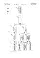
- FIG. 1 is a block diagram illustrating the overall configuration of an obstacle sensing apparatus for vehicles according to a preferred example of the present invention
- FIG. 2 is a flowchart illustrating an example of selection of a traveling path by selecting means
- FIG. 3 is a flowchart illustrating an example of identification of the nearest obstacle by identifying means
- FIG. 4 is a flowchart illustrating an example in which the distance between an automotive vehicle and the nearest obstacle is calculated by identifying means
- FIG. 5 is a schematic view showing the positional relationship between an automotive vehicle and a path of travel.
- FIG. 6 is a flowchart illustrating an example of a modification of this embodiment of selecting traveling path by selecting means.
- FIG. 1 is a block diagram illustrating the overall configuration of an obstacle sensing apparatus for a vehicle according to a preferred embodiment of the invention.
- the obstacle sensing apparatus in this embodiment is installed in an automotive vehicle along with an automatic braking system for automatically braking the wheels of the vehicle, and the sensing apparatus is so adapted that information representing obstacles sensed thereby is supplied for use in controlling the automatic braking system.
- a radar head unit 1 provided on the front of the vehicle body transmits a pulsed laser beam in the forward direction of the vehicle from a transmitter.
- the laser pulses serve as radar waves.
- the radar head 1 also has a receiver for receiving waves reflected back upon striking an obstacle such as a vehicle located ahead.
- the radar head unit 1 is of the scanning type, in which the pulsed laser beam transmitted by the transmitter is caused to scan across a comparatively wide angle in the horizontal direction.
- a signal from the radar head unit 1 enters an arithmetic unit 3 through a signal processor 2.
- the arithmetic unit 3 calculates the distance between the vehicle and each obstacle present within the scanned region as well as the direction to the each obstacle as seen from the vehicle.
- the laser head unit 1, signal processor 2 and arithmetic unit 3 construct a scanning-type radar unit 4 for sensing obstacles present ahead of the automotive vehicle.
- a steering angle sensor 5 serves as steering-angle sensing means for sensing the steering angle of a steering wheel.
- a vehicle velocity sensor 6 senses the velocity of the automotive vehicle.
- a yaw rate sensor 7 serves as yaw rate sensing means for sensing the yaw rate produced by the vehicle.
- the detection signal from the steering angle sensor 5 enters first traveling-path predicting means 8, the detection signal from the vehicle velocity sensor 6 enters the first traveling-path predicting means 8 and second traveling-path predicting means 9, and the detection signal from the yaw rate sensor enters the second traveling-path predicting means 9.
- the first traveling-path predicting means 8 predicts the path of travel of the vehicle based upon a steering angle ⁇ H and vehicle velocity V 0 . More specifically, the first traveling path predicting means 8 calculates radius of curvature R 1 of the traveling path (see the radius of curvature R in FIG. 5). Further, the first traveling-path predicting means 8 calculates a lateral slip angle ⁇ 1 of the vehicle. The radius of curvature R 1 and lateral slip angle ⁇ 1 are calculated in accordance with Equations (1) below.
- the second traveling-path predicting means 9 predicts the path of travel of the vehicle based upon a yaw rate ⁇ and vehicle velocity V 0 . More specifically, the predicting means 9 calculates radius of curvature R 2 of the traveling path (see the radius of curvature R in FIG. 5). Further, the second traveling-path predicting means 9 calculates a lateral slip angle ⁇ 2 of the vehicle. The radius of curvature R 2 and lateral slip angle ⁇ 2 are calculated in accordance with Equations (2) below. ##EQU1## where R 1 , ⁇ 1 are values calculated in accordance with Equations (1) and K f represents cornering power per front wheel.
- selecting unit 10 is adapted to select, in dependence upon the magnitude of the steering angle ⁇ H sensed by the steering angle sensor 5, either the path of travel predicted by the first traveling-path predicting means 8 or the path of travel predicted by the second traveling-path predicting means 9.
- Identifying unit 11 identifies the obstacle nearest the vehicle (this obstacle shall be referred to as the "nearest obstacle” below) from among the obstacles sensed by the radar unit 4 within a region along the path of travel selected by the selecting unit 10.
- the identification of the nearest obstacle by the identifying unit 11 is the same as sensing an obstacle by the radar unit 4 upon limiting detection to a region along the traveling path selected by the selecting unit 10.
- the identifying unit 11 possesses the function of control means for performing control in such a manner that detection of obstacles by the radar unit 4 is carried out upon being limited to a region along the traveling path selected by the selecting unit 10.
- the information representing the nearest obstacle identified by the identifying unit 11 enters a controller 21 of an automatic braking system so as to be utilized in, say, a judgment for determining the danger of collision between the vehicle and an obstacle.
- FIG. 2 is a flowchart illustrating a method of selecting a traveling path by the selecting unit 10
- FIG. 3 is a flowchart illustrating a method of identifying the nearest obstacle by the identifying unit 11
- FIG. 4 is a flowchart illustrating a method of calculating the distance between and an automotive vehicle and the nearest obstacle by the identifying unit 11.
- the selection of the path of travel by the selecting unit 10 is carried out in accordance with the flowchart of FIG. 2.
- the identification of the nearest obstacle by the identifying unit 11 is performed in accordance with the flowcharts of FIGS. 3 and 4.
- the steering angle ⁇ H sensed by the steering angle sensor 5, and the radii of curvature R 1 , R 2 of the traveling paths and the lateral slip angles ⁇ 1 , ⁇ 2 predicted by the traveling-path predicting means 8, 9, respectively, are read in first after the system is started. It is determined at step S2 whether the absolute value of the steering angle ⁇ H is less than a predetermined angle ⁇ c . When the steering angle ⁇ H is less than the predetermined angle ⁇ c (when a YES decision is rendered at step S2), the program proceeds to step S3.
- the path of travel predicted by the second traveling-path predicting means 9 is selected, R 2 is set as the radius of curvature of the path of travel and ⁇ 2 is set as the lateral slip angle ⁇ of the vehicle, after which the program returns.
- step S4 the program proceeds to step S4.
- the absolute value of the radius of curvature R 1 of the traveling path predicted by the first traveling-path predicting means 8 is compared with the absolute value of the radius of curvature R 2 of the traveling path predicted by the second traveling-path predicting means 9 to determine which is smaller.
- the program proceeds to step S5.
- R 1 is set as the radius of curvature R of the path of travel and ⁇ 1 is set as the lateral slip angle ⁇ of the vehicle, after which the program returns.
- R 2 of the traveling path predicted by the second traveling-path predicting means 9 is smaller (i.e., when a NO decision is rendered at step S4)
- the program proceeds to step S3.
- R 2 is set as the radius of curvature R of the path of travel and ⁇ 2 is set as the lateral slip angle ⁇ of the vehicle.
- R1 and R2 are compared at step S4 and the smaller radius of curvature is selected as the path of travel.
- step S11 calls for the data from the selecting unit 10, namely the turning (curvature) radius R and lateral slip angle ⁇ , to be acquired immediately after the system is started.
- step S12 at which the data from the arithmetic unit 3 of the radar unit 4 is acquired.
- the data from the radar unit 4 comprises data representing M-number of obstacles.
- step S13 where l n is made infinitely large, t n is made 0 and i is made 0 as initial settings.
- l n signifies the distance between the vehicle and the obstacle nearest to the vehicle from among the obstacles present in the path of travel.
- step S14 the program proceeds to step S14, at which i is counted up by one count.
- step S15 it is determined whether i is equal to or less than M.
- i is equal to or less than M (i.e., when a YES decision is rendered at step S15)
- step S16 the program proceeds to step S16, at which ⁇ 0 , ⁇ min , ⁇ max are calculated in accordance with Equations (3) below. ##EQU2##
- an included angle ⁇ 0 is an angle which a straight line a 2 connecting an automotive vehicle A and a center line CL of a traveling path B a distance L i ahead makes with a center line (the center line of the radar unit 4) a 1 of the vehicle A.
- a road width W represents distance laterally of the traveling path B.
- Included angles ⁇ min and ⁇ max are angles which straight lines connecting the vehicle A and left and right edges of the traveling path the distance L i ahead make with the center line (the center line of the radar unit 4) a 1 of the vehicle A.
- sign is taken as being positive in the clockwise direction.
- the radius of curvature R in FIG. 5 is the radius of curvature of the traveling path B. This is the turning radius of the vehicle.
- the lateral slip angle ⁇ is the included angle between the traveling direction of the vehicle A (which direction has a velocity vector of V 0 ) and the center line a 1 .
- step S17 at which the no-echo count C i is added to t 0 and the sum is set anew as t 0 .
- step S18 at which it is determined whether the horizontal angle ⁇ i of the obstacle is a value between ⁇ min and ⁇ max , i.e., whether the obstacle is on the traveling path B or not.
- step S19 at which it is determined whether the distance L i between the obstacle and the vehicle is less than l n .
- step S19 When L i if found to be smaller than ln at step S19 (i.e., when a YES decision is rendered at this step), the program proceeds to step S20, where the distance L i is set to l n and t 0 is set to t n . The program then returns to step S14.
- the horizontal angle ⁇ i of the obstacle is not a value between ⁇ min and ⁇ max , or when L i is equal to or greater than l n (i.e., when a NO decision is rendered at step S18 or S19)
- the program returns to step S14.
- the obstacle nearest the vehicle A on the traveling path B of the vehicle A is identified from among the M-number of obstacles sensed by the radar unit 4, and the distance between the nearest obstacle and the vehicle is set as l n .
- T is the time needed for one frame of scanning of the radar unit 4
- t 0 at step S21 is the time from the moment the nearest obstacle is sensed to the end of one frame of scanning of the radar unit 4.
- step S22 it is determined whether l n is infinitely large, namely whether the initially set value is still in effect. If the initially set value is still in effect (i.e., if a YES decision is rendered), then ln is set to 0 at step S23 and the program then proceeds to step S31. If ln is a finite value (i.e., if a NO decision is rendered), then the program proceeds directly to step S31 (FIG. 4).
- FIG. 4 is a flowchart from step S31 onward. It is determined at step S31 whether there is an obstacle (the nearest obstacle) in the path of travel. When the nearest article is present (i.e., when a YES decision is rendered), the n count is set to 0 at step S32 and various substitutions for measuring relative velocity are carried out at step S33. This is followed by step S34, at which the distance l 0 between the vehicle at the present time and the nearest obstacle is calculated by an interpolation method such as the law of least squares and the relative velocity V between the vehicle at the present time and the nearest obstacle is calculated using the distance l 0 . The program then returns.
- an obstacle the nearest obstacle
- the distance l 0 between the obstacle and the vehicle at the present time is calculated at step S37 by extrapolation using the data that prevailed previously.
- the relative velocity V between the vehicle at the present time and the nearest obstacle is calculated using the distance l 0 . The program then returns.
- the n count is set to 0 at step S38, after which l j , t j are set to 0 at step S39.
- the distance l 0 and the relative velocity V between the vehicle and the nearest obstacle are then set to 0 at step S40, after which the program returns.
- the vehicle When an automotive vehicle travels while negotiating a curve on a curved road that is canted (inclined), the vehicle undergoes turning motion owing to the cant even if the steering wheel is not turned a large amount.
- the radius of curvature R 2 of the traveling path predicted by the second traveling-path predicting means 9 based upon the yaw rate ⁇ becomes smaller than the radius of curvature R 1 of the traveling path predicted by the first traveling-path predicting means 8 based upon the steering angle ⁇ H .
- the second traveling path predicted by the second traveling-path predicting means 9 based upon the yaw rate ⁇ is selected and the radius of curvature R 2 of this traveling path is utilized in the identification of the nearest obstacle by the identifying unit 11.
- the identification of the nearest obstacle can be performed accurately by predicting the traveling path appropriately without being influence by the cant of the road.
- the first traveling-path predicting means 9 predicts that the traveling path will have the smaller radius of curvature R 1 in conformity with the steering angle ⁇ H , which will now have a larger value.
- This traveling path is selected by the selecting unit 10 and is utilized in the identification of the nearest obstacle by the identifying means 11. As a result, the prediction of the traveling path can be performed appropriately in full conformity with the sharp turning operation of the vehicle, thereby making it possible to improve reliability.
- the selecting unit 10 selects the traveling path predicted by the second traveling-path predicting means 9 based upon the yaw rate ⁇ , and the radius of curvature R 2 of this traveling path is utilized in the identification of the nearest obstacle by the identifying unit 11.
- the yaw rate ⁇ is not produced and, hence, the predicted traveling path is a straight path extending linearly in the traveling direction (straight ahead) of the vehicle. Accordingly, the prediction of the traveling path can be performed appropriately without any unnecessary follow-up of steering wheel operation.
- FIG. 6 is a flowchart illustrating a modification of a method of selecting a traveling path by the selecting unit 10 (see FIG. 1) according to this embodiment.
- the steering angle ⁇ H sensed by the steering angle sensor 5 and a steering-angle frequency (amount of change) F H are read in first after the system is started.
- the steering-angle frequency (amount of change) F H is calculated by differentiating the steering angle ⁇ H a single time or is sensed directly by a sensor.
- step S52 it is determined at step S52 whether the absolute value of the steering angle ⁇ H is less than the predetermined angle ⁇ c , and it is determined at step S53 whether the steering-angle frequency (amount of change) F H is greater than a predetermined value F c .
- the absolute value of the steering angle ⁇ H is less than the predetermined angle ⁇ c and the steering-angle frequency (amount of change) F H is greater than the predetermined value F c (i.e., when YES decisions are rendered at both steps S52 and S53)
- the radius of curvature R of the traveling path is set to infinity and the lateral slip angle ⁇ of the vehicle is set to 0 at step S54, after which the program returns.
- the values calculated in accordance with Equations (1) set forth earlier namely the radius of curvature R 1 of the traveling path and the lateral slip angle ⁇ 1 of the vehicle predicted by the first traveling-path predicting means 8 based upon the steering angle ⁇ H , are set respectively as the radius of curvature R of the traveling path and the lateral slip angle ⁇ of the vehicle, after which the program returns.
- this modification is equivalent to the second traveling-path predicting means 9 predicting unconditionally that the traveling path of the vehicle is a straight road lying directly in front of the vehicle and making the radius of curvature infinitely large.
- the traveling path predicted based upon the steering angle ⁇ H is selected and is utilized in the identification of the nearest obstacle by the identifying unit 11.
- the steering angle ⁇ H is smaller than the predetermined angle ⁇ c and the steering-angle frequency (amount of change) F H is greater than the predetermined value F c , that is, when the vehicle is traveling straight ahead while the steering wheel is being turned slightly back and forth, a straight path directed immediately ahead of the vehicle is selected and the infinite radius of curvature R is utilized in the identification of the nearest obstacle by the identifying unit 11. Accordingly, it is as if a dead zone were provided with regard to the prediction of the traveling bath based upon the steering angle. As a result, the prediction of a traveling path that unnecessarily follows up the steering angle ⁇ H can be prevented, and it is possible to predict the traveling path and, hence, detect obstacles, in an appropriate manner.
- an arrangement is set forth in which detection of obstacles is performed over a comparatively large angle in the horizontal direction by the radar unit 4, and only obstacles present in the path of travels are picked out from among the sensed obstacles while detection is in progress, thereby limiting, by software means, the detection of obstacles by the radar unit 4 to a region along the path of travel.
- the present invention can be similarly applied to an arrangement in which a radar unit having a narrow detection angle is provided so as to be capable of turning in the horizontal direction, and a radar detection area is provided in the direction of the traveling path of the vehicle, thereby limiting, by hardware means, the detection of obstacles by the radar unit to a region along the path of travel.
- a first traveling path is predicted based upon the steering angle of an automotive vehicle
- a second traveling path is predicted based upon a yaw rate produced by the vehicle
- either of the two traveling paths is selected in dependence upon the operating state of the vehicle so detection of obstacles by a radar unit is performed upon being limited to a region along the traveling path selected.
- prediction of traveling path can be performed appropriately in conformity with the operating state of the vehicle and detection of obstacles can be performed in an efficient manner.
- the second traveling path is selected when the steering angle is smaller than a predetermined value.
- the traveling path of the vehicle can be predicted appropriately as being a curved road close to reality in conformity also with the conditions of a road having a cant.
- a first traveling path of the vehicle is predicted based upon the steering angle of the vehicle, and what is directly ahead of the vehicle is predicted as being a traveling path.
- One of these traveling paths is selected in dependence upon the operating state of the vehicle so detection of obstacles by the radar unit is performed upon being limited to a region along the traveling path selected.
- prediction of traveling path can be performed appropriately in conformity with the operating state of the vehicle and detection of obstacles can be performed in an efficient manner.
- the second traveling path is selected, whereas the first traveling path is selected at all other times.
- a so-called dead zone is provided with regard to the prediction of the traveling bath based upon the steering angle.
- the prediction of a traveling path that unnecessarily follows up the steering angle can be prevented.
Abstract
Description
R.sub.1 =(1+A·V.sub.0.sup.2)·l·N/θ.sub.H
β.sub.1 =[-1+{m/(2·l)}·{l.sub.f /(l.sub.r ·K.sub.r)}·V.sub.0.sup.2 ]/(1+A·V.sub.0.sup.2)·(l.sub.r /l)·(θ.sub.H /N) (Eq. 1)
Claims (14)
Applications Claiming Priority (2)
| Application Number | Priority Date | Filing Date | Title |
|---|---|---|---|
| JP4-282724 | 1992-10-21 | ||
| JP28272492A JP3164439B2 (en) | 1992-10-21 | 1992-10-21 | Obstacle detection device for vehicles |
Publications (1)
| Publication Number | Publication Date |
|---|---|
| US5467283A true US5467283A (en) | 1995-11-14 |
Family
ID=17656222
Family Applications (1)
| Application Number | Title | Priority Date | Filing Date |
|---|---|---|---|
| US08/138,022 Expired - Fee Related US5467283A (en) | 1992-10-21 | 1993-10-19 | Obstacle sensing apparatus for vehicles |
Country Status (3)
| Country | Link |
|---|---|
| US (1) | US5467283A (en) |
| JP (1) | JP3164439B2 (en) |
| DE (1) | DE4335801B4 (en) |
Cited By (80)
| Publication number | Priority date | Publication date | Assignee | Title |
|---|---|---|---|---|
| US5648905A (en) * | 1993-12-07 | 1997-07-15 | Mazda Motor Corporation | Traveling control system for motor vehicle |
| US5709281A (en) * | 1995-09-14 | 1998-01-20 | Trw Inc. | Method and apparatus for adjusting steering feel |
| US5745870A (en) * | 1994-09-14 | 1998-04-28 | Mazda Motor Corporation | Traveling-path prediction apparatus and method for vehicles |
| US5754099A (en) * | 1994-03-25 | 1998-05-19 | Nippondenso Co., Ltd. | Obstacle warning system for a vehicle |
| US5761629A (en) * | 1994-12-13 | 1998-06-02 | Lucas Industries Public Limited Company | Method and apparatus for cruise control |
| GB2320326A (en) * | 1996-12-12 | 1998-06-17 | Samsung Electronics Co Ltd | Collision warning by path prediction of a vehicle |
| WO1999019745A1 (en) * | 1997-10-09 | 1999-04-22 | Eaton Vorad Technologies, L.L.C. | Method and apparatus for in-path target determination for an automotive vehicle using a gyroscopic device |
| US5926126A (en) * | 1997-09-08 | 1999-07-20 | Ford Global Technologies, Inc. | Method and system for detecting an in-path target obstacle in front of a vehicle |
| US5930739A (en) * | 1995-04-07 | 1999-07-27 | Regie Nationale Des Usines Renault | Method for measuring the yaw velocity of a vehicle |
| US5964822A (en) * | 1997-08-27 | 1999-10-12 | Delco Electronics Corp. | Automatic sensor azimuth alignment |
| US6157892A (en) * | 1998-06-11 | 2000-12-05 | Honda Giken Kogyo Kabushiki Kaisha | Obstacle avoidance control system for vehicle |
| EP1065520A2 (en) * | 1999-06-28 | 2001-01-03 | Hitachi, Ltd. | Vehicle control method and vehicle warning method |
| US6212465B1 (en) * | 1999-12-22 | 2001-04-03 | Visteon Global Technologies Inc. | Method and system for controlling vehicle speed based on vehicle yaw rate and yaw acceleration |
| US6226571B1 (en) * | 1998-06-03 | 2001-05-01 | Mitsubishi Denki Kabushiki Kaisha | Surroundings monitoring apparatus for an automotive vehicle |
| US6230093B1 (en) * | 1997-05-31 | 2001-05-08 | Robert Bosch Gmbh | Method and device for determining the probable path to be covered by a vehicle |
| US6269307B1 (en) * | 1998-08-06 | 2001-07-31 | Honda Giken Kogyo Kabushiki Kaisha | Travel safety system for vehicle |
| US6272418B1 (en) * | 1997-12-12 | 2001-08-07 | Honda Giken Kogyo Kabushiki Kaisha | Integrated control system of vehicle |
| US6289281B1 (en) * | 1997-12-12 | 2001-09-11 | Honda Giken Kogyo Kabushiki Kaisha | Integrated control system of vehicle |
| EP1060937A3 (en) * | 1999-06-15 | 2001-09-12 | Nissan Motor Company, Limited | Vehicular velocity controlling apparatus and method to follow up a preceding vehicle on curves |
| WO2001079013A1 (en) * | 2000-04-14 | 2001-10-25 | Robert Bosch Gmbh | Distance-related method for controlling the speed of a vehicle |
| US20020038176A1 (en) * | 1999-12-22 | 2002-03-28 | Visteon Global Technologies, Inc. | Method and system for controlling vehicle deceleration in an adaptive speed control system based on vehicle speed |
| US6369700B1 (en) * | 1998-08-27 | 2002-04-09 | Toyota Jidosha Kabushiki Kaisha | On-vehicle DBF radar apparatus |
| US20020044082A1 (en) * | 2000-08-16 | 2002-04-18 | Woodington Walter Gordon | Radar detection method and apparatus |
| US20020049539A1 (en) * | 2000-09-08 | 2002-04-25 | Russell Mark E. | Path prediction system and method |
| US20020067287A1 (en) * | 2000-08-16 | 2002-06-06 | Delcheccolo Michael Joseph | Near object detection system |
| US20020072843A1 (en) * | 2000-08-16 | 2002-06-13 | Russell Mark E. | Safe distance algorithm for adaptive cruise control |
| US6408241B1 (en) * | 2001-02-05 | 2002-06-18 | Visteon Global Technologies, Inc. | Method and system for controlling vehicle speed based on vehicle yaw rate and yaw acceleration |
| US20020075138A1 (en) * | 2000-08-16 | 2002-06-20 | Van Rees H. Barteld | Portable object detection system |
| EP1223093A2 (en) * | 2001-01-09 | 2002-07-17 | Nissan Motor Company, Limited | Braking control system with object detection system interaction |
| US20020163478A1 (en) * | 2000-08-16 | 2002-11-07 | Pleva Joseph S. | Switched beam antenna architecture |
| US6498972B1 (en) | 2002-02-13 | 2002-12-24 | Ford Global Technologies, Inc. | Method for operating a pre-crash sensing system in a vehicle having a countermeasure system |
| US20030004633A1 (en) * | 2001-03-14 | 2003-01-02 | Russell Mark E. | Safe distance algorithm for adaptive cruise control |
| US6519519B1 (en) | 2002-02-01 | 2003-02-11 | Ford Global Technologies, Inc. | Passive countermeasure methods |
| US6542807B2 (en) * | 1998-12-22 | 2003-04-01 | Mannesmann Vdo Ag | Device for representing a control situation determined by a motor vehicle distance control device |
| US6573859B2 (en) | 2000-02-07 | 2003-06-03 | Toyota Jidosha Kabushiki Kaisha | Radar apparatus |
| US6611227B1 (en) | 2002-08-08 | 2003-08-26 | Raytheon Company | Automotive side object detection sensor blockage detection system and related techniques |
| US6621448B1 (en) | 2002-04-05 | 2003-09-16 | The Regents Of The University Of California | Non-contact radar system for reconstruction of scenes obscured under snow and similar material |
| US20030210182A1 (en) * | 2000-08-16 | 2003-11-13 | Hanson James T. | Video amplifier for a radar receiver |
| US20030210172A1 (en) * | 2000-08-16 | 2003-11-13 | Pleva Joseph S. | Technique for changing a range gate and radar coverage |
| US6679702B1 (en) | 2001-12-18 | 2004-01-20 | Paul S. Rau | Vehicle-based headway distance training system |
| US20040024498A1 (en) * | 2000-11-29 | 2004-02-05 | Mitsubishi Denki Kabushiki Kaisha | Vehicle surroundings monitoring apparatus |
| US20040064241A1 (en) * | 2002-09-18 | 2004-04-01 | Fuji Jukogyo Kabushiki Kaisha | Vehicle surroundings monitoring apparatus and traveling control system incorporating the apparatus |
| US6721659B2 (en) | 2002-02-01 | 2004-04-13 | Ford Global Technologies, Llc | Collision warning and safety countermeasure system |
| US20040111200A1 (en) * | 2001-11-29 | 2004-06-10 | Rao Manoharprasad K. | Vehicle sensing based pre-crash threat assessment system |
| US6753804B2 (en) | 2002-05-21 | 2004-06-22 | Visteon Global Technologies, Inc. | Target vehicle identification based on the theoretical relationship between the azimuth angle and relative velocity |
| US6763904B2 (en) * | 2000-04-14 | 2004-07-20 | Robert Bosch Gmbh | Method for adjusting the speed of a motor vehicle |
| US20040143416A1 (en) * | 2003-01-17 | 2004-07-22 | Toyota Jidosha Kabushiki Kaisha | Curve's radius estimation device |
| US6772062B2 (en) | 2001-05-31 | 2004-08-03 | The Regents Of The University Of California | Intelligent ultra high speed distributed sensing system and method for sensing roadway markers for intelligent vehicle guidance and control |
| US6775605B2 (en) | 2001-11-29 | 2004-08-10 | Ford Global Technologies, Llc | Remote sensing based pre-crash threat assessment system |
| US6795765B2 (en) * | 2001-03-22 | 2004-09-21 | Visteon Global Technologies, Inc. | Tracking of a target vehicle using adaptive cruise control |
| US6831572B2 (en) | 2002-01-29 | 2004-12-14 | Ford Global Technologies, Llc | Rear collision warning system |
| US6853906B1 (en) * | 1998-12-01 | 2005-02-08 | Robert Bosch Gmbh | Method and device for determining a future travel-path area of a vehicle |
| WO2005017554A1 (en) * | 2003-08-18 | 2005-02-24 | Fico Mirrors, Sa | System and method for monitoring the external environment of a motor vehicle |
| US20050209766A1 (en) * | 2004-03-19 | 2005-09-22 | Perisho Robert A Jr | Automatic lateral acceleration limiting and non threat target rejection |
| WO2005093686A1 (en) * | 2004-02-20 | 2005-10-06 | Fico Mirrors, Sa | System for controlling the operation of presence-detection devices and implementation method thereof |
| US20050228580A1 (en) * | 2002-04-27 | 2005-10-13 | Hermann Winner | Method and device for predicting the course of motor vehicles |
| GB2413449A (en) * | 2004-02-12 | 2005-10-26 | Neil Sim | Vehicular based forward scanning device for collision avoidance |
| US6970142B1 (en) | 2001-08-16 | 2005-11-29 | Raytheon Company | Antenna configurations for reduced radar complexity |
| US6995730B2 (en) | 2001-08-16 | 2006-02-07 | Raytheon Company | Antenna configurations for reduced radar complexity |
| US7009500B2 (en) | 2002-02-13 | 2006-03-07 | Ford Global Technologies, Llc | Method for operating a pre-crash sensing system in a vehicle having a countermeasure system using stereo cameras |
| US20060109168A1 (en) * | 2002-07-05 | 2006-05-25 | Motoi Nakanishi | Radar |
| EP1714108A2 (en) * | 2003-12-24 | 2006-10-25 | Automotive Systems Laboratory Inc. | Road curvature estimation system |
| US7158870B2 (en) | 2002-01-24 | 2007-01-02 | Ford Global Technologies, Llc | Post collision restraints control module |
| US20070030131A1 (en) * | 2005-08-02 | 2007-02-08 | Nissan Motor Co., Ltd. | Vehicle obstacle verification system |
| US7183995B2 (en) | 2001-08-16 | 2007-02-27 | Raytheon Company | Antenna configurations for reduced radar complexity |
| US20070129891A1 (en) * | 2005-11-28 | 2007-06-07 | Mitsubishi Denki Kabushiki Kaisha | Automatic vehicle braking device |
| US20090038873A1 (en) * | 2004-12-06 | 2009-02-12 | Bernhard Lucas | Method And Device For Controlling Automatic Emergency Braking |
| US20090210114A1 (en) * | 2004-11-29 | 2009-08-20 | Daimlerchrysler Ag | Method for a Safety System in a Vehicle |
| US20090326752A1 (en) * | 2005-08-18 | 2009-12-31 | Martin Staempfle | Method for detecting a traffic zone |
| US20100094541A1 (en) * | 2007-06-16 | 2010-04-15 | Bayerische Motoren Werke Aktiengesellschaft | Method for Assisting a Motor Vehicle Driver When Driving Through a Narrow Passage and/or for Maintaining a Safe Distance from a Vehicle in Front |
| US20100250064A1 (en) * | 2009-03-24 | 2010-09-30 | Hitachi Automotive Systems, Ltd. | Control apparatus for vehicle in which traveling environment recognition apparatus is installed |
| US20110153139A1 (en) * | 2009-12-17 | 2011-06-23 | Sick Ag | Optoelectronic sensor |
| US7973701B2 (en) | 2008-03-31 | 2011-07-05 | Valeo Radar Systems, Inc. | Automotive radar sensor blockage detection system and related techniques |
| CN101612930B (en) * | 2008-06-26 | 2011-08-17 | 比亚迪股份有限公司 | Automotive guard and alarm device and automotive guard and alarm method |
| US20110264302A1 (en) * | 2008-12-26 | 2011-10-27 | Toyota Jidosha Kabushiki Kaisha | Travel route estimation device and travel route estimation method used in the same device |
| US20130120161A1 (en) * | 2010-09-28 | 2013-05-16 | Aisin Seiki Kabushiki Kaisha | Parking assistance device |
| CN103503045A (en) * | 2011-04-27 | 2014-01-08 | 丰田自动车株式会社 | Neighboring vehicle detecting apparatus |
| GB2510167A (en) * | 2013-01-28 | 2014-07-30 | Jaguar Land Rover Ltd | Vehicle path prediction and obstacle indication system |
| WO2020131385A1 (en) * | 2018-12-20 | 2020-06-25 | Trimble Inc. | Automated assessment of collision risk based on computer vision |
| USRE49387E1 (en) * | 1991-12-23 | 2023-01-24 | Blanding Hovenweep, Llc | Ergonomic man-machine interface incorporating adaptive pattern recognition based control system |
Families Citing this family (17)
| Publication number | Priority date | Publication date | Assignee | Title |
|---|---|---|---|---|
| DE4407757A1 (en) * | 1993-03-08 | 1994-09-15 | Mazda Motor | Device for detecting obstacles for a vehicle |
| JP2788189B2 (en) * | 1994-05-20 | 1998-08-20 | 富士通テン株式会社 | Inter-vehicle distance measuring device |
| DE4437365C2 (en) * | 1994-10-19 | 2001-05-10 | Telefunken Microelectron | Method for determining the traffic area in front of a motor vehicle |
| DE19655360B4 (en) * | 1996-11-04 | 2010-12-09 | Valeo Schalter Und Sensoren Gmbh | Method and distance measuring device for the distance measurement of obstacles dependent on the vehicle data |
| DE19729952A1 (en) * | 1997-07-12 | 1999-01-14 | Opel Adam Ag | Vehicle with distance warning device |
| JP2002537542A (en) * | 1997-08-25 | 2002-11-05 | マンネスマン ファウ デー オー アクチエンゲゼルシャフト | Method and apparatus for locating a control object |
| DE10141037C1 (en) * | 2001-08-20 | 2003-04-03 | Siemens Ag | Obstacle detection device |
| DE10221900A1 (en) * | 2002-05-16 | 2003-11-27 | Volkswagen Ag | Determination of the radius of curvature of a road uses vehicle speed and yaw measurements in mathematical models to generate output for vehicle control |
| JP2004101481A (en) * | 2002-09-12 | 2004-04-02 | Matsushita Electric Works Ltd | Radar apparatus |
| DE10351883A1 (en) * | 2003-10-30 | 2005-06-02 | Valeo Schalter Und Sensoren Gmbh | Motor vehicle employs computer program procedure to represent detection area around vehicle |
| JP4754856B2 (en) * | 2005-03-31 | 2011-08-24 | 株式会社デンソーアイティーラボラトリ | Automotive radar equipment |
| JP4046742B2 (en) * | 2005-07-14 | 2008-02-13 | 三菱電機株式会社 | Road shape estimation device |
| JP2009041981A (en) * | 2007-08-07 | 2009-02-26 | Nissan Motor Co Ltd | Object detection system and vehicle equipped with object detection system |
| DE102007053705B4 (en) * | 2007-11-10 | 2021-12-02 | Volkswagen Ag | Trajectory estimation for turning maneuvers |
| JP2009217728A (en) * | 2008-03-12 | 2009-09-24 | Mazda Motor Corp | Obstacle detector for vehicle |
| JP2009258775A (en) * | 2008-04-11 | 2009-11-05 | Mazda Motor Corp | Lane deviation alarm device for vehicle |
| US10137893B2 (en) * | 2016-09-26 | 2018-11-27 | Keith J. Hanna | Combining driver alertness with advanced driver assistance systems (ADAS) |
Citations (6)
| Publication number | Priority date | Publication date | Assignee | Title |
|---|---|---|---|---|
| JPS517892A (en) * | 1973-10-26 | 1976-01-22 | Tokyo Shibaura Electric Co | |
| US4519469A (en) * | 1981-09-07 | 1985-05-28 | Toyota Jidosha Kabushiki Kaisha | Method and apparatus for automatic control of driving speed |
| US4670845A (en) * | 1983-12-06 | 1987-06-02 | Nissan Motor Company, Limited | System and method for automatically controlling vehicle speed |
| US5233527A (en) * | 1990-03-19 | 1993-08-03 | Honda Giken Kogyo Kabushiki Kaisha | Automatic travelling apparatus |
| US5249128A (en) * | 1990-11-16 | 1993-09-28 | Texas Instruments Incorporated | System and method for determining the distance to an energy emitting object |
| US5314037A (en) * | 1993-01-22 | 1994-05-24 | Shaw David C H | Automobile collision avoidance system |
Family Cites Families (5)
| Publication number | Priority date | Publication date | Assignee | Title |
|---|---|---|---|---|
| JPS517892B1 (en) * | 1970-11-07 | 1976-03-11 | ||
| DE3034199A1 (en) * | 1979-01-08 | 1982-04-22 | Robert Bosch Gmbh, 7000 Stuttgart | Automobile speed regulating device maintaining correct vehicle spacing - monitors steering wheel movement to disconnect spacing control around bends |
| JPS5766028A (en) * | 1980-10-06 | 1982-04-22 | Nissan Motor Co Ltd | Alarming device for vehicle |
| DE4029426C2 (en) * | 1989-09-27 | 2000-02-24 | Volkswagen Ag | Method and device for determining the change in direction or curvature of a roadway |
| IT1240974B (en) * | 1990-07-05 | 1993-12-27 | Fiat Ricerche | METHOD AND EQUIPMENT TO AVOID THE COLLISION OF A VEHICLE AGAINST OBSTACLES. |
-
1992
- 1992-10-21 JP JP28272492A patent/JP3164439B2/en not_active Expired - Fee Related
-
1993
- 1993-10-19 US US08/138,022 patent/US5467283A/en not_active Expired - Fee Related
- 1993-10-20 DE DE4335801A patent/DE4335801B4/en not_active Expired - Fee Related
Patent Citations (6)
| Publication number | Priority date | Publication date | Assignee | Title |
|---|---|---|---|---|
| JPS517892A (en) * | 1973-10-26 | 1976-01-22 | Tokyo Shibaura Electric Co | |
| US4519469A (en) * | 1981-09-07 | 1985-05-28 | Toyota Jidosha Kabushiki Kaisha | Method and apparatus for automatic control of driving speed |
| US4670845A (en) * | 1983-12-06 | 1987-06-02 | Nissan Motor Company, Limited | System and method for automatically controlling vehicle speed |
| US5233527A (en) * | 1990-03-19 | 1993-08-03 | Honda Giken Kogyo Kabushiki Kaisha | Automatic travelling apparatus |
| US5249128A (en) * | 1990-11-16 | 1993-09-28 | Texas Instruments Incorporated | System and method for determining the distance to an energy emitting object |
| US5314037A (en) * | 1993-01-22 | 1994-05-24 | Shaw David C H | Automobile collision avoidance system |
Cited By (132)
| Publication number | Priority date | Publication date | Assignee | Title |
|---|---|---|---|---|
| USRE49387E1 (en) * | 1991-12-23 | 2023-01-24 | Blanding Hovenweep, Llc | Ergonomic man-machine interface incorporating adaptive pattern recognition based control system |
| US5648905A (en) * | 1993-12-07 | 1997-07-15 | Mazda Motor Corporation | Traveling control system for motor vehicle |
| US5754099A (en) * | 1994-03-25 | 1998-05-19 | Nippondenso Co., Ltd. | Obstacle warning system for a vehicle |
| US5745870A (en) * | 1994-09-14 | 1998-04-28 | Mazda Motor Corporation | Traveling-path prediction apparatus and method for vehicles |
| US5761629A (en) * | 1994-12-13 | 1998-06-02 | Lucas Industries Public Limited Company | Method and apparatus for cruise control |
| US5930739A (en) * | 1995-04-07 | 1999-07-27 | Regie Nationale Des Usines Renault | Method for measuring the yaw velocity of a vehicle |
| US5709281A (en) * | 1995-09-14 | 1998-01-20 | Trw Inc. | Method and apparatus for adjusting steering feel |
| GB2320326B (en) * | 1996-12-12 | 2000-05-31 | Samsung Electronics Co Ltd | Method for guiding a driver by predicting the progress path of a car |
| GB2320326A (en) * | 1996-12-12 | 1998-06-17 | Samsung Electronics Co Ltd | Collision warning by path prediction of a vehicle |
| US6230093B1 (en) * | 1997-05-31 | 2001-05-08 | Robert Bosch Gmbh | Method and device for determining the probable path to be covered by a vehicle |
| US5964822A (en) * | 1997-08-27 | 1999-10-12 | Delco Electronics Corp. | Automatic sensor azimuth alignment |
| US5926126A (en) * | 1997-09-08 | 1999-07-20 | Ford Global Technologies, Inc. | Method and system for detecting an in-path target obstacle in front of a vehicle |
| US5959569A (en) * | 1997-10-09 | 1999-09-28 | Eaton Vorad Technologies, L.L.C. | Method and apparatus for in path target determination for an automotive vehicle using a gyroscopic device |
| WO1999019745A1 (en) * | 1997-10-09 | 1999-04-22 | Eaton Vorad Technologies, L.L.C. | Method and apparatus for in-path target determination for an automotive vehicle using a gyroscopic device |
| AU743214B2 (en) * | 1997-10-09 | 2002-01-24 | Eaton Vorad Technologies, L.L.C. | Method and apparatus for in-path target determination for an automotive vehicule using a gyroscopic device |
| US6272418B1 (en) * | 1997-12-12 | 2001-08-07 | Honda Giken Kogyo Kabushiki Kaisha | Integrated control system of vehicle |
| US6289281B1 (en) * | 1997-12-12 | 2001-09-11 | Honda Giken Kogyo Kabushiki Kaisha | Integrated control system of vehicle |
| US6226571B1 (en) * | 1998-06-03 | 2001-05-01 | Mitsubishi Denki Kabushiki Kaisha | Surroundings monitoring apparatus for an automotive vehicle |
| US6157892A (en) * | 1998-06-11 | 2000-12-05 | Honda Giken Kogyo Kabushiki Kaisha | Obstacle avoidance control system for vehicle |
| US6269307B1 (en) * | 1998-08-06 | 2001-07-31 | Honda Giken Kogyo Kabushiki Kaisha | Travel safety system for vehicle |
| US6369700B1 (en) * | 1998-08-27 | 2002-04-09 | Toyota Jidosha Kabushiki Kaisha | On-vehicle DBF radar apparatus |
| US6853906B1 (en) * | 1998-12-01 | 2005-02-08 | Robert Bosch Gmbh | Method and device for determining a future travel-path area of a vehicle |
| US6542807B2 (en) * | 1998-12-22 | 2003-04-01 | Mannesmann Vdo Ag | Device for representing a control situation determined by a motor vehicle distance control device |
| EP1060937A3 (en) * | 1999-06-15 | 2001-09-12 | Nissan Motor Company, Limited | Vehicular velocity controlling apparatus and method to follow up a preceding vehicle on curves |
| US6567737B2 (en) | 1999-06-28 | 2003-05-20 | Hitachi, Ltd. | Vehicle control method and vehicle warning method |
| US6311123B1 (en) | 1999-06-28 | 2001-10-30 | Hitachi, Ltd. | Vehicle control method and vehicle warning method |
| EP1065520A3 (en) * | 1999-06-28 | 2001-05-02 | Hitachi, Ltd. | Vehicle control method and vehicle warning method |
| EP1065520A2 (en) * | 1999-06-28 | 2001-01-03 | Hitachi, Ltd. | Vehicle control method and vehicle warning method |
| EP1720036A1 (en) * | 1999-06-28 | 2006-11-08 | Hitachi, Ltd. | Vehicle control method and vehicle warning method |
| US6317679B2 (en) | 1999-12-22 | 2001-11-13 | Visteon Global Technologies, Inc. | Method and system for controlling vehicle speed based on vehicle yaw rate and yaw acceleration |
| US6393352B2 (en) * | 1999-12-22 | 2002-05-21 | Visteon Global Technologies, Inc. | Method and system for controlling vehicle deceleration in an adaptive speed control system based on vehicle speed |
| US6212465B1 (en) * | 1999-12-22 | 2001-04-03 | Visteon Global Technologies Inc. | Method and system for controlling vehicle speed based on vehicle yaw rate and yaw acceleration |
| US20020038176A1 (en) * | 1999-12-22 | 2002-03-28 | Visteon Global Technologies, Inc. | Method and system for controlling vehicle deceleration in an adaptive speed control system based on vehicle speed |
| US6604043B2 (en) | 1999-12-22 | 2003-08-05 | Visteon Global Technologies, Inc. | Method and system for controlling vehicle deceleration in an adaptive speed control system based on vehicle speed |
| US6573859B2 (en) | 2000-02-07 | 2003-06-03 | Toyota Jidosha Kabushiki Kaisha | Radar apparatus |
| US6763904B2 (en) * | 2000-04-14 | 2004-07-20 | Robert Bosch Gmbh | Method for adjusting the speed of a motor vehicle |
| US6721645B2 (en) | 2000-04-14 | 2004-04-13 | Robert Bosch Gmbh | Distance-related method for controlling the speed of a vehicle |
| WO2001079013A1 (en) * | 2000-04-14 | 2001-10-25 | Robert Bosch Gmbh | Distance-related method for controlling the speed of a vehicle |
| US20030001772A1 (en) * | 2000-08-16 | 2003-01-02 | Woodington Walter Gordon | Radar detection method and apparatus |
| US6977609B2 (en) | 2000-08-16 | 2005-12-20 | Raytheon Company | Technique for changing a range gate and radar coverage |
| US7071868B2 (en) | 2000-08-16 | 2006-07-04 | Raytheon Company | Radar detection method and apparatus |
| US20020044082A1 (en) * | 2000-08-16 | 2002-04-18 | Woodington Walter Gordon | Radar detection method and apparatus |
| US6903679B2 (en) | 2000-08-16 | 2005-06-07 | Raytheon Company | Video amplifier for a radar receiver |
| US20020163478A1 (en) * | 2000-08-16 | 2002-11-07 | Pleva Joseph S. | Switched beam antenna architecture |
| US20020147534A1 (en) * | 2000-08-16 | 2002-10-10 | Delcheccolo Michael Joseph | Near object detection system |
| US6864831B2 (en) | 2000-08-16 | 2005-03-08 | Raytheon Company | Radar detection method and apparatus |
| US6577269B2 (en) | 2000-08-16 | 2003-06-10 | Raytheon Company | Radar detection method and apparatus |
| US20020075178A1 (en) * | 2000-08-16 | 2002-06-20 | Woodington Walter Gordon | Radar transmitter circuitry and techniques |
| US6784828B2 (en) | 2000-08-16 | 2004-08-31 | Raytheon Company | Near object detection system |
| US20020075138A1 (en) * | 2000-08-16 | 2002-06-20 | Van Rees H. Barteld | Portable object detection system |
| US6707419B2 (en) | 2000-08-16 | 2004-03-16 | Raytheon Company | Radar transmitter circuitry and techniques |
| US6642908B2 (en) | 2000-08-16 | 2003-11-04 | Raytheon Company | Switched beam antenna architecture |
| US20030210182A1 (en) * | 2000-08-16 | 2003-11-13 | Hanson James T. | Video amplifier for a radar receiver |
| US20030210172A1 (en) * | 2000-08-16 | 2003-11-13 | Pleva Joseph S. | Technique for changing a range gate and radar coverage |
| US6670910B2 (en) | 2000-08-16 | 2003-12-30 | Raytheon Company | Near object detection system |
| US20020067287A1 (en) * | 2000-08-16 | 2002-06-06 | Delcheccolo Michael Joseph | Near object detection system |
| US20020072843A1 (en) * | 2000-08-16 | 2002-06-13 | Russell Mark E. | Safe distance algorithm for adaptive cruise control |
| US6683557B2 (en) | 2000-08-16 | 2004-01-27 | Raytheon Company | Technique for changing a range gate and radar for coverage |
| US20020049539A1 (en) * | 2000-09-08 | 2002-04-25 | Russell Mark E. | Path prediction system and method |
| US6675094B2 (en) | 2000-09-08 | 2004-01-06 | Raytheon Company | Path prediction system and method |
| US20040024498A1 (en) * | 2000-11-29 | 2004-02-05 | Mitsubishi Denki Kabushiki Kaisha | Vehicle surroundings monitoring apparatus |
| US6862527B2 (en) * | 2000-11-29 | 2005-03-01 | Mitsubishi Denki Kabushiki Kaisha | Vehicle surroundings monitoring apparatus |
| EP1223093A2 (en) * | 2001-01-09 | 2002-07-17 | Nissan Motor Company, Limited | Braking control system with object detection system interaction |
| EP1223093A3 (en) * | 2001-01-09 | 2003-08-20 | Nissan Motor Company, Limited | Braking control system with object detection system interaction |
| US6408241B1 (en) * | 2001-02-05 | 2002-06-18 | Visteon Global Technologies, Inc. | Method and system for controlling vehicle speed based on vehicle yaw rate and yaw acceleration |
| US20030004633A1 (en) * | 2001-03-14 | 2003-01-02 | Russell Mark E. | Safe distance algorithm for adaptive cruise control |
| US6708100B2 (en) | 2001-03-14 | 2004-03-16 | Raytheon Company | Safe distance algorithm for adaptive cruise control |
| US6795765B2 (en) * | 2001-03-22 | 2004-09-21 | Visteon Global Technologies, Inc. | Tracking of a target vehicle using adaptive cruise control |
| US6772062B2 (en) | 2001-05-31 | 2004-08-03 | The Regents Of The University Of California | Intelligent ultra high speed distributed sensing system and method for sensing roadway markers for intelligent vehicle guidance and control |
| US7183995B2 (en) | 2001-08-16 | 2007-02-27 | Raytheon Company | Antenna configurations for reduced radar complexity |
| US6995730B2 (en) | 2001-08-16 | 2006-02-07 | Raytheon Company | Antenna configurations for reduced radar complexity |
| US6970142B1 (en) | 2001-08-16 | 2005-11-29 | Raytheon Company | Antenna configurations for reduced radar complexity |
| US20040111200A1 (en) * | 2001-11-29 | 2004-06-10 | Rao Manoharprasad K. | Vehicle sensing based pre-crash threat assessment system |
| US6819991B2 (en) | 2001-11-29 | 2004-11-16 | Ford Global Technologies, Llc | Vehicle sensing based pre-crash threat assessment system |
| US6775605B2 (en) | 2001-11-29 | 2004-08-10 | Ford Global Technologies, Llc | Remote sensing based pre-crash threat assessment system |
| US6679702B1 (en) | 2001-12-18 | 2004-01-20 | Paul S. Rau | Vehicle-based headway distance training system |
| US7158870B2 (en) | 2002-01-24 | 2007-01-02 | Ford Global Technologies, Llc | Post collision restraints control module |
| US6831572B2 (en) | 2002-01-29 | 2004-12-14 | Ford Global Technologies, Llc | Rear collision warning system |
| US6721659B2 (en) | 2002-02-01 | 2004-04-13 | Ford Global Technologies, Llc | Collision warning and safety countermeasure system |
| US6519519B1 (en) | 2002-02-01 | 2003-02-11 | Ford Global Technologies, Inc. | Passive countermeasure methods |
| US6498972B1 (en) | 2002-02-13 | 2002-12-24 | Ford Global Technologies, Inc. | Method for operating a pre-crash sensing system in a vehicle having a countermeasure system |
| US7009500B2 (en) | 2002-02-13 | 2006-03-07 | Ford Global Technologies, Llc | Method for operating a pre-crash sensing system in a vehicle having a countermeasure system using stereo cameras |
| US6621448B1 (en) | 2002-04-05 | 2003-09-16 | The Regents Of The University Of California | Non-contact radar system for reconstruction of scenes obscured under snow and similar material |
| US20050228580A1 (en) * | 2002-04-27 | 2005-10-13 | Hermann Winner | Method and device for predicting the course of motor vehicles |
| US8126640B2 (en) * | 2002-04-27 | 2012-02-28 | Robert Bosch Gmbh | Method and device for predicting the course of motor vehicles |
| US6753804B2 (en) | 2002-05-21 | 2004-06-22 | Visteon Global Technologies, Inc. | Target vehicle identification based on the theoretical relationship between the azimuth angle and relative velocity |
| US20060109168A1 (en) * | 2002-07-05 | 2006-05-25 | Motoi Nakanishi | Radar |
| US7230565B2 (en) * | 2002-07-05 | 2007-06-12 | Murata Manufacturing Co., Ltd. | Radar |
| US6611227B1 (en) | 2002-08-08 | 2003-08-26 | Raytheon Company | Automotive side object detection sensor blockage detection system and related techniques |
| US20040064241A1 (en) * | 2002-09-18 | 2004-04-01 | Fuji Jukogyo Kabushiki Kaisha | Vehicle surroundings monitoring apparatus and traveling control system incorporating the apparatus |
| US6961661B2 (en) * | 2002-09-18 | 2005-11-01 | Fuji Jukogyo Kabushiki Kaisha | Vehicle surroundings monitoring apparatus and traveling control system incorporating the apparatus |
| US7447577B2 (en) * | 2003-01-17 | 2008-11-04 | Toyota Jidosha Kabushiki Kaisha | Curve's radius estimation device |
| US20040143416A1 (en) * | 2003-01-17 | 2004-07-22 | Toyota Jidosha Kabushiki Kaisha | Curve's radius estimation device |
| WO2005017554A1 (en) * | 2003-08-18 | 2005-02-24 | Fico Mirrors, Sa | System and method for monitoring the external environment of a motor vehicle |
| US7392118B2 (en) | 2003-08-18 | 2008-06-24 | Fico Mirrors, Sa | System and method for monitoring the external environment of a motor vehicle |
| US20060111819A1 (en) * | 2003-08-18 | 2006-05-25 | Llorenc Servera Serapio | System and method for monitoring the external environment of a motor vehicle |
| EP1714108A4 (en) * | 2003-12-24 | 2010-01-13 | Automotive Systems Lab | Road curvature estimation system |
| EP1714108A2 (en) * | 2003-12-24 | 2006-10-25 | Automotive Systems Laboratory Inc. | Road curvature estimation system |
| GB2413449A (en) * | 2004-02-12 | 2005-10-26 | Neil Sim | Vehicular based forward scanning device for collision avoidance |
| WO2005093686A1 (en) * | 2004-02-20 | 2005-10-06 | Fico Mirrors, Sa | System for controlling the operation of presence-detection devices and implementation method thereof |
| US20080012696A1 (en) * | 2004-02-20 | 2008-01-17 | Carlos Segura Gordillo | Control System for the Operation of Presence Detection Devices and Method Therefor |
| US7463166B2 (en) | 2004-02-20 | 2008-12-09 | Fico Mirrors, S.A. | Control system for the operation of presence detection devices and method therefor |
| US7512475B2 (en) * | 2004-03-19 | 2009-03-31 | Delphi Technologies, Inc. | Automatic lateral acceleration limiting and non threat target rejection |
| US20050209766A1 (en) * | 2004-03-19 | 2005-09-22 | Perisho Robert A Jr | Automatic lateral acceleration limiting and non threat target rejection |
| US8146703B2 (en) * | 2004-11-29 | 2012-04-03 | Daimler Ag | Method for a safety system in a vehicle |
| US20090210114A1 (en) * | 2004-11-29 | 2009-08-20 | Daimlerchrysler Ag | Method for a Safety System in a Vehicle |
| US20090038873A1 (en) * | 2004-12-06 | 2009-02-12 | Bernhard Lucas | Method And Device For Controlling Automatic Emergency Braking |
| US7975798B2 (en) * | 2004-12-06 | 2011-07-12 | Robert Bosch Gmbh | Method and device for controlling automatic emergency braking |
| US7532109B2 (en) * | 2005-08-02 | 2009-05-12 | Nissan Motor Co., Ltd. | Vehicle obstacle verification system |
| US20070030131A1 (en) * | 2005-08-02 | 2007-02-08 | Nissan Motor Co., Ltd. | Vehicle obstacle verification system |
| US20090326752A1 (en) * | 2005-08-18 | 2009-12-31 | Martin Staempfle | Method for detecting a traffic zone |
| US8818694B2 (en) * | 2005-08-18 | 2014-08-26 | Robert Bosch Gmbh | Method for detecting a traffic zone |
| US7734416B2 (en) * | 2005-11-28 | 2010-06-08 | Mitsubishi Denki Kabushiki Kaisha | Automatic vehicle braking device |
| US20070129891A1 (en) * | 2005-11-28 | 2007-06-07 | Mitsubishi Denki Kabushiki Kaisha | Automatic vehicle braking device |
| US20100094541A1 (en) * | 2007-06-16 | 2010-04-15 | Bayerische Motoren Werke Aktiengesellschaft | Method for Assisting a Motor Vehicle Driver When Driving Through a Narrow Passage and/or for Maintaining a Safe Distance from a Vehicle in Front |
| US10214143B2 (en) | 2007-06-16 | 2019-02-26 | Bayerische Motoren Werke Aktiengesellschaft | Method for assisting a motor vehicle driver when driving through a narrow passage and/or for maintaining a safe distance from a vehicle in front |
| US7973701B2 (en) | 2008-03-31 | 2011-07-05 | Valeo Radar Systems, Inc. | Automotive radar sensor blockage detection system and related techniques |
| CN101612930B (en) * | 2008-06-26 | 2011-08-17 | 比亚迪股份有限公司 | Automotive guard and alarm device and automotive guard and alarm method |
| US20110264302A1 (en) * | 2008-12-26 | 2011-10-27 | Toyota Jidosha Kabushiki Kaisha | Travel route estimation device and travel route estimation method used in the same device |
| US8989913B2 (en) * | 2008-12-26 | 2015-03-24 | Toyota Jidosha Kabushiki Kaisha | Travel route estimation device and travel route estimation method used in the same device |
| US20100250064A1 (en) * | 2009-03-24 | 2010-09-30 | Hitachi Automotive Systems, Ltd. | Control apparatus for vehicle in which traveling environment recognition apparatus is installed |
| US20110153139A1 (en) * | 2009-12-17 | 2011-06-23 | Sick Ag | Optoelectronic sensor |
| US8406950B2 (en) * | 2009-12-17 | 2013-03-26 | Sick Ag | Optoelectronic sensor |
| US20130120161A1 (en) * | 2010-09-28 | 2013-05-16 | Aisin Seiki Kabushiki Kaisha | Parking assistance device |
| CN103503045A (en) * | 2011-04-27 | 2014-01-08 | 丰田自动车株式会社 | Neighboring vehicle detecting apparatus |
| WO2014114813A1 (en) * | 2013-01-28 | 2014-07-31 | Jaguar Land Rover Limited | Motor vehicle system and method |
| CN104955714A (en) * | 2013-01-28 | 2015-09-30 | 捷豹路虎有限公司 | Motor vehicle system and method |
| GB2510167B (en) * | 2013-01-28 | 2017-04-19 | Jaguar Land Rover Ltd | Vehicle path prediction and obstacle indication system and method |
| US9944319B2 (en) | 2013-01-28 | 2018-04-17 | Jaguar Land Rover Limited | Motor vehicle system and method |
| GB2510167A (en) * | 2013-01-28 | 2014-07-30 | Jaguar Land Rover Ltd | Vehicle path prediction and obstacle indication system |
| WO2020131385A1 (en) * | 2018-12-20 | 2020-06-25 | Trimble Inc. | Automated assessment of collision risk based on computer vision |
| US10817732B2 (en) | 2018-12-20 | 2020-10-27 | Trimble Inc. | Automated assessment of collision risk based on computer vision |
Also Published As
| Publication number | Publication date |
|---|---|
| DE4335801A1 (en) | 1994-04-28 |
| JPH06131596A (en) | 1994-05-13 |
| DE4335801B4 (en) | 2007-04-05 |
| JP3164439B2 (en) | 2001-05-08 |
Similar Documents
| Publication | Publication Date | Title |
|---|---|---|
| US5467283A (en) | Obstacle sensing apparatus for vehicles | |
| US5479173A (en) | Obstacle sensing apparatus for vehicles | |
| US5995037A (en) | Obstacle detection system for a vehicle | |
| JP3045401B2 (en) | How to check the roadway ahead of a car | |
| US5467284A (en) | Obstacle detection system for motor vehicle | |
| US6166628A (en) | Arrangement and method for detecting objects from a motor vehicle | |
| JP2910377B2 (en) | Radar equipment for vehicles | |
| JP3913911B2 (en) | Vehicle obstacle detection device | |
| JPH076291A (en) | Obstacle sensor for automobile | |
| JP2765314B2 (en) | Automotive radar equipment | |
| JP4082286B2 (en) | Front object position detection device | |
| JP3400088B2 (en) | Vehicle travel path estimation device | |
| JP3135722B2 (en) | Vehicle safety devices | |
| JPH05159199A (en) | Device for detecting approach | |
| JPH11144198A (en) | Object identifying device for vehicle | |
| JPH05223933A (en) | Obstacle detection apparatus | |
| JP2859928B2 (en) | Rear monitoring device for vehicles | |
| JP3209671B2 (en) | Curved road judgment device | |
| JPH1062532A (en) | Radar for vehicle | |
| JPH05342500A (en) | Car to car distance detecting device | |
| JP3582217B2 (en) | Obstacle detection device | |
| JPH07295633A (en) | Travel path estimation device for automobile | |
| JP3400093B2 (en) | Vehicle travel path estimation device | |
| JPH1123706A (en) | Obstacle detecting device for vehicle | |
| JPH07306996A (en) | Estimating device for traveling course for automobile |
Legal Events
| Date | Code | Title | Description |
|---|---|---|---|
| AS | Assignment |
Owner name: MAZDA MOTOR CORPORATION, JAPAN Free format text: ASSIGNMENT OF ASSIGNORS INTEREST;ASSIGNORS:BUTSUEN, TETSURO;YOSHIOKA, TOHRU;UEMURA, HIROKI;AND OTHERS;REEL/FRAME:006736/0042 Effective date: 19931013 |
|
| CC | Certificate of correction | ||
| FEPP | Fee payment procedure |
Free format text: PAYOR NUMBER ASSIGNED (ORIGINAL EVENT CODE: ASPN); ENTITY STATUS OF PATENT OWNER: LARGE ENTITY |
|
| FPAY | Fee payment |
Year of fee payment: 4 |
|
| FPAY | Fee payment |
Year of fee payment: 8 |
|
| REMI | Maintenance fee reminder mailed | ||
| LAPS | Lapse for failure to pay maintenance fees | ||
| STCH | Information on status: patent discontinuation |
Free format text: PATENT EXPIRED DUE TO NONPAYMENT OF MAINTENANCE FEES UNDER 37 CFR 1.362 |
|
| FP | Lapsed due to failure to pay maintenance fee |
Effective date: 20071114 |