US5471395A - Control of CNC machine tools - Google Patents
Control of CNC machine tools Download PDFInfo
- Publication number
- US5471395A US5471395A US08/157,091 US15709193A US5471395A US 5471395 A US5471395 A US 5471395A US 15709193 A US15709193 A US 15709193A US 5471395 A US5471395 A US 5471395A
- Authority
- US
- United States
- Prior art keywords
- axis
- axes
- programmable
- machine
- joint
- Prior art date
- Legal status (The legal status is an assumption and is not a legal conclusion. Google has not performed a legal analysis and makes no representation as to the accuracy of the status listed.)
- Expired - Lifetime
Links
Images


Classifications
-
- G—PHYSICS
- G05—CONTROLLING; REGULATING
- G05B—CONTROL OR REGULATING SYSTEMS IN GENERAL; FUNCTIONAL ELEMENTS OF SUCH SYSTEMS; MONITORING OR TESTING ARRANGEMENTS FOR SUCH SYSTEMS OR ELEMENTS
- G05B19/00—Programme-control systems
- G05B19/02—Programme-control systems electric
- G05B19/18—Numerical control [NC], i.e. automatically operating machines, in particular machine tools, e.g. in a manufacturing environment, so as to execute positioning, movement or co-ordinated operations by means of programme data in numerical form
- G05B19/41—Numerical control [NC], i.e. automatically operating machines, in particular machine tools, e.g. in a manufacturing environment, so as to execute positioning, movement or co-ordinated operations by means of programme data in numerical form characterised by interpolation, e.g. the computation of intermediate points between programmed end points to define the path to be followed and the rate of travel along that path
- G05B19/4103—Digital interpolation
-
- G—PHYSICS
- G05—CONTROLLING; REGULATING
- G05B—CONTROL OR REGULATING SYSTEMS IN GENERAL; FUNCTIONAL ELEMENTS OF SUCH SYSTEMS; MONITORING OR TESTING ARRANGEMENTS FOR SUCH SYSTEMS OR ELEMENTS
- G05B19/00—Programme-control systems
- G05B19/02—Programme-control systems electric
- G05B19/18—Numerical control [NC], i.e. automatically operating machines, in particular machine tools, e.g. in a manufacturing environment, so as to execute positioning, movement or co-ordinated operations by means of programme data in numerical form
- G05B19/406—Numerical control [NC], i.e. automatically operating machines, in particular machine tools, e.g. in a manufacturing environment, so as to execute positioning, movement or co-ordinated operations by means of programme data in numerical form characterised by monitoring or safety
- G05B19/4068—Verifying part programme on screen, by drawing or other means
-
- G—PHYSICS
- G05—CONTROLLING; REGULATING
- G05B—CONTROL OR REGULATING SYSTEMS IN GENERAL; FUNCTIONAL ELEMENTS OF SUCH SYSTEMS; MONITORING OR TESTING ARRANGEMENTS FOR SUCH SYSTEMS OR ELEMENTS
- G05B19/00—Programme-control systems
- G05B19/02—Programme-control systems electric
- G05B19/18—Numerical control [NC], i.e. automatically operating machines, in particular machine tools, e.g. in a manufacturing environment, so as to execute positioning, movement or co-ordinated operations by means of programme data in numerical form
- G05B19/408—Numerical control [NC], i.e. automatically operating machines, in particular machine tools, e.g. in a manufacturing environment, so as to execute positioning, movement or co-ordinated operations by means of programme data in numerical form characterised by data handling or data format, e.g. reading, buffering or conversion of data
- G05B19/4086—Coordinate conversions; Other special calculations
-
- G—PHYSICS
- G05—CONTROLLING; REGULATING
- G05B—CONTROL OR REGULATING SYSTEMS IN GENERAL; FUNCTIONAL ELEMENTS OF SUCH SYSTEMS; MONITORING OR TESTING ARRANGEMENTS FOR SUCH SYSTEMS OR ELEMENTS
- G05B2219/00—Program-control systems
- G05B2219/30—Nc systems
- G05B2219/33—Director till display
- G05B2219/33131—Synthesize programmable axis, to simulate a non existing, virtual axis
-
- G—PHYSICS
- G05—CONTROLLING; REGULATING
- G05B—CONTROL OR REGULATING SYSTEMS IN GENERAL; FUNCTIONAL ELEMENTS OF SUCH SYSTEMS; MONITORING OR TESTING ARRANGEMENTS FOR SUCH SYSTEMS OR ELEMENTS
- G05B2219/00—Program-control systems
- G05B2219/30—Nc systems
- G05B2219/34—Director, elements to supervisory
- G05B2219/34164—Superposition manual control pulses on motion control pulses
-
- G—PHYSICS
- G05—CONTROLLING; REGULATING
- G05B—CONTROL OR REGULATING SYSTEMS IN GENERAL; FUNCTIONAL ELEMENTS OF SUCH SYSTEMS; MONITORING OR TESTING ARRANGEMENTS FOR SUCH SYSTEMS OR ELEMENTS
- G05B2219/00—Program-control systems
- G05B2219/30—Nc systems
- G05B2219/35—Nc in input of data, input till input file format
- G05B2219/35373—Data storage, buffer
-
- G—PHYSICS
- G05—CONTROLLING; REGULATING
- G05B—CONTROL OR REGULATING SYSTEMS IN GENERAL; FUNCTIONAL ELEMENTS OF SUCH SYSTEMS; MONITORING OR TESTING ARRANGEMENTS FOR SUCH SYSTEMS OR ELEMENTS
- G05B2219/00—Program-control systems
- G05B2219/30—Nc systems
- G05B2219/35—Nc in input of data, input till input file format
- G05B2219/35459—Knob, handle, handwheel delivers pulses, electronic handwheel, digipot
-
- G—PHYSICS
- G05—CONTROLLING; REGULATING
- G05B—CONTROL OR REGULATING SYSTEMS IN GENERAL; FUNCTIONAL ELEMENTS OF SUCH SYSTEMS; MONITORING OR TESTING ARRANGEMENTS FOR SUCH SYSTEMS OR ELEMENTS
- G05B2219/00—Program-control systems
- G05B2219/30—Nc systems
- G05B2219/43—Speed, acceleration, deceleration control ADC
- G05B2219/43158—Feedrate override
-
- G—PHYSICS
- G05—CONTROLLING; REGULATING
- G05B—CONTROL OR REGULATING SYSTEMS IN GENERAL; FUNCTIONAL ELEMENTS OF SUCH SYSTEMS; MONITORING OR TESTING ARRANGEMENTS FOR SUCH SYSTEMS OR ELEMENTS
- G05B2219/00—Program-control systems
- G05B2219/30—Nc systems
- G05B2219/50—Machine tool, machine tool null till machine tool work handling
- G05B2219/50157—Universal swivel spindle head, swivel in all directions
-
- G—PHYSICS
- G05—CONTROLLING; REGULATING
- G05B—CONTROL OR REGULATING SYSTEMS IN GENERAL; FUNCTIONAL ELEMENTS OF SUCH SYSTEMS; MONITORING OR TESTING ARRANGEMENTS FOR SUCH SYSTEMS OR ELEMENTS
- G05B2219/00—Program-control systems
- G05B2219/30—Nc systems
- G05B2219/50—Machine tool, machine tool null till machine tool work handling
- G05B2219/50208—Retrace, remachine portion of path, locus to remove start discontinuities
Definitions
- This invention relates to multi-axis computer numerically controlled (CNC) machine tools in which a cutting tool is movable relative to a workpiece under the control of programmable control means including a computer program known as a "part program”.
- CNC computer numerically controlled
- cutting tool refers to the portion of the machine that is designed to act upon the workpiece to perform the desired task.
- the cutting tool is not restricted to standard turning or milling cutters, but also includes all mechanical, electronic and/or electro-mechanical devices used to modify the shape and/or properties of the workpiece.
- cutting tools include: end-mills, turning tools, grinding wheels, laser cutting beams, plasma beams and punch tools.
- Multi-axis CNC machine tools conventionally include a plurality of movable machine members and a plurality of controllable joints movable to cause the cutting tool to move relative to a fixed frame of reference (eg. the machine base).
- the workpiece may be mounted on workpiece mounting means which is fixed relative to the machine base.
- the workpiece may be mounted on workpiece mounting means connected to the machine base by further movable machine members and controllable joints.
- the joints of a multi-axis machine tool may include prismatic (linear) joints which enable a machine part to be moved in a linear direction and rotary joints which enable a machine part to be rotated about a rotary axis.
- the programmable control means of a multi-axis CNC machine tool is conventionally programmed to control the position and orientation of the joints to cause the cutting tool to occupy a desired position and orientation relative to the workpiece mounting means.
- multi- or multiple axis control when used in the context of CNC machine tools, conventionally refers to a form of CNC control in which the machine may be programmed to control one or more joints concurrently.
- the development of multi-axis and multifunction machine tools in conjunction with the development of sophisticated computer controlled operations has facilitated the emergence of a generation of very high speed precision machine tools capable of complex multi-step operations from one machine.
- a plurality of programmable positioning directions or "axes" are chosen which constitute the minimum number of axes required to position the cutting tool relative to the workpiece.
- These programmable axes referred to herein as principal programmable axes may include up to three linear orthogonal axes and one or more rotary axes.
- a CNC machine tool has a number of programmable axes and is controlled by part program which serially instructs the machine to perform a sequential series of discrete operations in a predetermined or programmed sequence.
- a four axis machine tool may have three orthogonal linear or prismatic joints providing control of movement in three orthogonal directions (X, Y and Z), and one rotary joint providing rotation about a rotary axis A.
- the directions X, Y and Z may conveniently be chosen as programmable linear axes and the axis A chosen as a programmable rotary axis.
- U.S. Pat. No. 4,591,771 discloses a numerical control system for a five axis CNC machine tool of the type having three linear or prismatic joints controlled by servo motors which provide relative movement between the tool and the workpiece in the directions of the X, Y and Z axes of an orthogonal co-ordinate system and two rotary joints controlled by servo motors which provide rotary movement in the directions of B and C axes of a spherical co-ordinate system.
- the orthogonal axes X, Y and Z and the rotary axes B and C may be conveniently chosen as programmable axes.
- the five axis CNC machine of U.S. Pat. No. 4,591,771 also includes a manual pulse generator which allows the machine tool to be moved manually in the axial direction A of the machine tool relative to the workpiece to increase or decrease the cutting amount.
- a method of operating a multi-axis CNC machine tool having workpiece mounting means for mounting a workpiece, a cutting tool operable upon said workpiece, a plurality of machine members and a plurality of controllable joint means movable under the control of a program to cause relative movement between the cutting tool and the workpiece mounting means,
- said method comprising the steps of programming the machine with a plurality of principal programmable positioning directions or axes which axes constitute the minimum number of axes required to position the cutting tool relative to the workpiece mounting means, and programming the machine to control movement of the joint means in accordance with a part program so as to cause the cutting tool to move along a programmed path relative to the workpiece mounting means,
- the method being characterized by the step of programming the machine to synthesize at least one additional programmable axis whereby relative movement of said cutting tool and said workpiece mounting means is automatically controllable in relation to said additional programmable axis in accordance with said part program without physical location of said additional programmable axis by joint means.
- a multi-axis CNC machine tool comprising:
- controllable joint means movable to cause the relative movement between said cutting tool and said workpiece mounting means
- programmable control means programmed to control automatically the position and orientation of said plurality of joint means in accordance with a part program
- the machine tool having a plurality of principal programmable positioning directions or axes which constitute the minimum number of programmable axes required to position and orientate the cutting tool relative to the workpiece mounting means;
- the machine is programmed to synthesize at least one additional programmable axis, whereby movement of said cutting tool or said workpiece mounting means in relation to said at least one additional programmable axis is automatically controllable in accordance with said part program without physical location of said at least one synthesized additional programmable axis by joint means.
- the CNC machine may be programmed to synthesize more than one additional programmable axis, allowing movement of the cutting tool or the workpiece in relation to each one of the additional programmable axes to be controlled without physical location of said synthesized additional programmable axes.
- the or each synthesized additional programmable axis may be hereinafter referred to as a "soft axis", with the principal programmable axes being referred to as "principal hard axes”.
- At least one of said synthesized additional programmable axes or "soft" axes is non-collinear with the principal programmable axes.
- non-collinear axes would be regarded as partially redundant axes since it is possible to describe any required position or orientation of the cutting tool relative to the workpiece in terms of co-ordinates of the principal "hard" axes.
- a soft axis which is collinear with one of the other soft axes may be regarded as a fully redundant axis, although it will be appreciated that the present invention in its broadest form includes the synthesis by electronic or computational means of any "soft" axis, whether it is partially redundant or fully redundant.
- Soft axes are fully programmable axes capable of simulating normal axis operations such as: interpolation, contouring, splicing, offsetting, jogging, manual positioning and live offset positioning.
- At least one of said synthesized additional programmable axes or soft axes is arranged to pass through a part of the cutting tool and to remain fixed relative to the cutting tool.
- the synthesis of such a soft axis enables the machine to be programmed to control linear movement of a rotatable cutting tool either along a soft axis coinciding with the axis of rotation of the cutting tool or to control the cutting tool to contour around a soft rotary axis, for instance an axis passing through a grinding point at the edge of the cutting tool.
- FIG. 1 is a schematic diagram of a simple prior art CNC machine tool having four "hard” axes and four joints;
- FIG. 2 is a schematic diagram of a simple CNC machine tool in accordance with the invention having three principal "hard” axes, a partly redundant “soft” axis and three joints;
- FIG. 3 is a block diagram of a co-ordinate transform module for a CNC machine tool in accordance with the invention having five principal "hard” axes, two “soft” axes and five joints;
- FIG. 4 is a perspective view of the workpiece and grinding wheel of a CNC tool grinder having five principal "hard” axes, two “soft” axes and five joints;
- FIG. 5 is a perspective view showing the joint layout for the CNC tool grinder of FIG. 4;
- FIG. 6 is a perspective view of the workpiece and grinding wheel of a CNC cylindrical grinder having four principal "hard” axes, two “soft” axes and four joints;
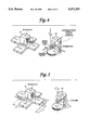
- FIG. 7 is a perspective view of the laser cutter of a CNC laser cutting machine tool having five principal "hard” axes, three “soft” axes and five joints.
- FIG. 8 is a perspective view of the workpiece and cutting tool of a CNC milling machine having five principal "hard” axes, three “soft” axes and five joints.
- the CNC machine tool illustrated schematically in FIG. 1 is a simple, conventional machine tool comprising a programmable control unit or PCU 1, a trajectory interpolator 2, a position controller 4, a machine base 5 having mounting means 8 for mounting a workpiece 6 thereon, a rotatable cutting tool 7, a plurality of movable machine members L 1 to L 3 , a plurality of joints J 1 -J 4 and a respective actuator 11 to 14 associated with each joint J 1 -J 4 .
- the first joint J 1 is a linear or prismatic joint forming a telescopic linkage between a part of the machine base 5 and the first machine member L 1 and providing movement of machine member L 1 relative to the base 5 in a horizontal direction X
- the second joint J 2 is a linear or prismatic joint forming a telescopic linkage between the first machine member L 1 and the second machine member L 2 , and providing relative linear movement between the first and second machine members L 1 and L 2 in a vertical direction Z
- the third joint J 3 is a rotary joint between the second and third machine members L 2 and L 3 and providing angular movement of the third machine member L 3 relative to the second machine member L 2 about a rotary axis B
- the fourth joint J 4 is a linear or prismatic joint forming a telescopic linkage between the third machine member L 3 and the head of the cutting tool 7 providing linear movement of the cutting tool 7 relative to the third machine member L 3 in a direction V coinciding with the axis of rotation
- a machine tool such as that of FIG. 1 is often referred to as a "four axis machine” because it has four joints J 1 to J 4 .
- the machine is also considered to have four machine degrees of freedom (MDOF) because it has four non-collinear joint axes or directions in which relative movement between adjacent machine members or between the cutting tool and the third machine member may take place, ie: linear axes X, Z and V and rotary axis B.
- MDOF machine degrees of freedom
- the CNC machine tool of FIG. 1 is considered to have three principal axes, known as principal "hard” axes, ie: orthogonal linear axes X and Z and rotary axis B.
- Linear axis V is known as a partially redundant "hard” axis, since any change in linear position of the cutting tool 7 in the V direction relative to the workpiece 6 could be expressed in terms of the change in co-ordinates of the X and Z axes.
- the program would define the relative positions of the joints J 1 to J 4 and the movable machine members M 1 to M 3 relative to a point of reference on the fixed workpiece known as the workpiece reference point in terms of coordinates from the X, Z and B principal "hard” axes and the partially redundant "hard axis" V.
- the number of programming degrees of freedom (PDOF) in the machine of FIG. 1 is four, equal to the number of machine degrees of freedom (MDOF), ie. the number of Joints.
- the machine tool illustrated schematically in FIG. 2 is similar to that of FIG. 1 and corresponding reference numerals have been applied to corresponding parts.
- the machine tool of FIG. 2 differs physically from that of FIG. 1 in that the third machine member L 3 , the fourth joint J 4 and its associated actuator 14 have been omitted.
- the machine tool of FIG. 2 includes a co-ordinate transform module 3 and, by suitable programming of the PCU 1 and the co-ordinate transform module 3, is able to control movement of the cutting tool 7 relative to the workpiece reference point in the same linear directions X, Z and V and about the same rotary axes B and C as the machine tool of FIG. 1 despite the fact that there is no physical location of linear axis V by means of a joint since joint J 4 has been omitted.
- the three joint machine of FIG. 2 is able to position the cutting tool relative to the workpiece as effectively as the four joint machine of FIG. 1 because the co-ordinate transform module 3 is programmed to synthesize a partially redundant "soft" axis corresponding to linear axis V which passes through the cutting tool 7. It will be appreciated that linear movement of the cutting tool 7 in the direction V' is possible by appropriate actuation of prismatic joints J 1 and J 2 without physically locating the linear axis V by means of a corresponding joint J 4 .
- the machine Since the machine has only three joints, J 1 , J 2 , and J 3 it only has three machine degrees of freedom (MDOF) but because an additional partially redundant "soft" axis is synthesized, the machine has four programming degrees of freedom (PDOF). In this manner, the three joint or three axis machine of FIG. 2 can operate in the same way as the four joint machine of FIG. 1.
- MDOF machine degrees of freedom
- PDOF programming degrees of freedom
- FIG. 3 shows a co-ordinate transform module 3 of a machine having five joints J 1 to J 5 , five principal "hard” axes and two partially redundant "soft” axes.
- the cutting tool is the portion of the machine that is designed to act upon a workpiece to perform the desired task.
- the cutting tool is not restricted to standard turning or milling cutters, but also includes all mechanical, electronic and/or electro-mechanical devices used to modify the shape and/or properties of the workpiece.
- cutting tools include: end-mills, turning tools, grinding wheels, laser cutting beams, plasma beams and punch tools.
- the workpiece is the part upon which useful work is done by the machine tool.
- the principal job of the machine tool is to modify a workpiece's shape and/or properties.
- WRP Workpiece Reference Point
- the workpiece reference point is a point of reference, logically attached to the workpiece. It is located as a fixed position relative to the workpiece but this position may be programmed be means other than using axes.
- a machine member is an essentially rigid mechanical structure of the machine tool or a combination of mechanical structures that result in a mathematically constant link between 2 joints J n and J n+1 or between the base of the machine and joint J 1 or between joint J N and the cutting tool (where N is the number of joints in the machine tool).
- the last machine member is the machine member that attaches joint J N to the cutting tool where N is the number of joints in the machine tool.
- a joint is controlled by means of an actuator.
- the position of a joint describes the kinematic relationship between one machine member and another.
- each joint position maps directly and simply to the position of one actuator.
- a simple N to N mapping occurs between joint positions and actuator positions however, this is rare for most normal machine tools.
- Typical actuators are electrical servo motors, pneumatic and hydraulic pistons.
- TRP Tool Reference Point
- the tool reference point is a point of reference, logically attached to the last machine member of the machine tool. It is located as a fixed position relative to the last machine member but this position may be programmed be means other than using axes.
- a rotating cutting tool is a cutting tool designed to spin about a particular axis, whereby useful work is done by the swept volume of the cutting tool. This implies that the orientation of the cutting tool is limited to 2 degrees of freedom; the third degree of freedom (rotation about the spinning axis) has no meaning.
- SDOF Spacial Degrees of Freedom
- a machine tool can be defined as having SDOF spacial degrees of freedom and ODOF orientation degrees of freedom.
- the spacial degrees of freedom (SDOF) of a machine tool is an integral number that represents the fundamental space that the machine tool is designed to operate in. This space is called SDOF-Dimensional Euclidean Space which may be defined as a rectangular coordinate system with SDOF euclidean dimensions embedded in the workpiece at the workpiece reference point. This reference frame and its corresponding euclidean space are used herein as the base frame when referencing the position and orientation of the machine tool.
- the number of SDOF will be one of:
- SDOF is defined as the minimum number of Euclidean space dimensions required to fully describe the set of fundamental axis direction vectors for all linear axes and the set of fundamental axis direction vectors for all rotary axes for all axis vector values within the working envelope of the machine tool.
- ODOF Orientation Degrees of Freedom
- the orientation degrees of freedom (ODOF) of a machine tool is an integral number that represents the fundamental degrees of freedom that the orientation of the cutting tool may make with respect to the workpiece.
- ODOF is the number of different direction vectors D n (maximum of 3) (each of which is orthogonal to all other D m ) about which the cutting tool may be programmed to rotate (using the rotary axes and linear axes) for all axis vector values within the working envelope of the machine tool for which the tool reference point remains in contact with the workpiece reference point.
- This definition does not imply that the cutting tool cannot be rotated about more than ODOF direction axes over the entire working envelope. It refers to the number of degrees of rotary freedom given a fixed position of the tool reference point with respect to the workpiece reference point. At a different position (or in a different programmed configuration) the cutting tool may rotate about a different direction vector.
- the number of ODOF will be one of:
- a rotary axis designed to rotate the workpiece can not be used in the calculation of ODOF and SDOF. It is counted either as an axis used to effect principal positioning of the tool reference point with respect to the workpiece reference point (eg: theta in a cylindrical coordinate position system) or as an axis used to effect principal orientation of the tool reference point with respect to the workpiece reference point.
- an axis is a "programmable" positioning direction.
- the principal means of programming a CNC to position the machine tool to a particular position is to specify the destination point as a set of axis positions.
- Typical names for axes are: X, Y, Z, A, B, C, U, X1, X2, A3 etc.
- Axes may be either linear axes or rotary axes.
- axes are represented as A n where n represents the location of the axis in the axis vector.
- the axis position of an axis (say A n ) is the value that the axis has been programmed to reach after all programmed transformations have been accounted for.
- An axis vector (A) is a vectorial representation of the position of the machine tool expressed as a column matrix (M+1 ⁇ 1) where each element of the vector represents the axis position of one of the M axes of the machine tool. The last element in the vector is the value 1. This is used for homogeneity of the vector: ##EQU1## where: a i represents the position of axis i. NOTE: Whilst A is referred to as an axis vector, it bears no direct relationship to a normal 3-dimensional Euclidean space vector.
- the position matrix (P) is a representation that combines the position of the tool reference point (TRP) in SDOF-dimensional euclidean space (with respect to the workpiece reference point (WRP)) with the orientation of the cutting tool (with respect to SDOF-dimensional euclidean space).
- P can be represented as follows: ##EQU2## where: N is called the normal orientation vector (see below).
- O is called the orient orientation vector (see below).
- A is called the approach orientation vector (see below).
- P is called the position vector (see below).
- orientation vectors are called orientation vectors. They form an orthogonal set of unit vectors, whose values (in SDOF-dimensional euclidean space) represent the orientation of the cutting tool with respect to the workpiece. This set of vectors can encompass up to 3 orientation degrees of freedom (which is the maximum allowed). These vectors can be defined as follows: ##EQU3## where: N x is the i axis position of the vector N in SDOF-dimensional euclidean space.
- N y is the j axis position of the vector N in SDOF-dimensional euclidean space.
- N z is the k axis position of the vector N in SDOF-dimensional euclidean space.
- the axis matrix (A) is a symbolic 4 ⁇ 4 matrix that defines the kinematic relationship between the position matrix (P) and the axis position of each of the axes (a n ); which are the elements of the axis vector (A).
- the elements of A are expressed symbolically in terms of a n .sub.(for n-1 . . . N) where N is the number of axes in the machine tool.
- A is defined as: ##EQU4## where: f ij (A) is a function of the components of A (a x , a 2 . . . a N ) .
- An axis is a linear axis if, for all current axis vector (A') values within the working envelope of the machine tool, the following equations are true: ##EQU5## where: a n is the component direction of the axis vector corresponding to A n .
- ⁇ a n is a scalar representing the displacement of axis A n from the axis position at A'.
- A' is the current axis vector.
- A is the axis matrix.
- P is the position vector (see the definition of position matrix).
- N, O and A are the orientation vectors (see the definition of position matrix).
- K is a scalar constant
- a rotary axis is an axis that causes the orientation of the cutting tool (with respect to SDOF-dimensional euclidean space) to change.
- a rotary axis satisfies at least one of the following criteria: ##EQU6## where: a n is the component rotation of the axis vector corresponding to A n .
- A' is the current axis vector.
- A is the axis matrix.
- P is the position vector (see the definition of position matrix).
- N, O and A are the orientation vectors (see the definition of position matrix).
- Two or more linear axes are defined as being collinear if they satisfy the following criteria:
- the fundamental axis direction vectors (D n a (A') of the axes form a collinear set of vectors for all axis vector values within the working envelope of the machine tool. ie: A linear axis (say A n ) is collinear to another linear axis (A m ) if the direction of movement of A n always coincides with the direction of movement of A m regardless of the position of the machine tool. This is expressed in the following equation:
- K is a scalar constant.
- a third axis (A p ) is collinear to A n if it is collinear to A n . Note: This definition does not imply that the fundamental axis direction vectors of a collinear axis set are constant. It only relates to the relative linear dependence of the set.
- the current axis vector (A') is the value of the axis vector A at the current position of the machine tool.
- the fundamental axis direction vector (D a n (A')) for a linear axis A n is defined as the vector that relates the rate of change of the position of the tool reference point (with respect to the workpiece reference point) in SDOF-dimensional euclidean space to the rate of change in the position of A n at the current axis vector. It is represented by the solution of the partial differential equation at the current axis vector: ##EQU7## where: a n is the component direction of the axis vector corresponding to A n .
- A' is the current axis vector.
- A is the axis matrix.
- P is the position vector (see the definition of position matrix)
- N, O and A are the orientation vectors (see the definition of position matrix).
- Two or more rotary axes are defined as being collinear if they satisfy the following criteria:
- the fundamental axis rotation vectors (R a n (A')) of the axes form a collinear set of vectors for all axis vector values within the working envelope of the machine tool and the fundamental axis rotation origin vectors (V a n (A')) of the axes are identical for all axis vector values within the working envelope of the machine tool.
- a rotary axis (say A n ) is collinear to another rotary axis (A m ) if the direction of rotation of A n always coincides with the direction of rotation of A m and the origin of rotation of A n is always the same as the origin of rotation of A m regardless of the position of the machine tool. This is expressed in the following equations:
- K is the scalar constant 1 or -1.
- a third axis (A p ) is collinear to A m if it is collinear to A n , Note: This definition does not imply that the fundamental axis rotation vectors or fundamental axis rotation origin vectors of a collinear axis set are constant, It only relates to the relative linear dependence and equality of the set.
- the fundamental axis rotation origin vector (V a n (A')) for the rotary axis A n defines the instantaneous location of the axis of rotation of A n in SDOF-dimensional euclidean space at the current axis vector (A'). It is defined by the following equation: ##EQU8## where: a n is the component rotation of the axis vector corresponding to A n ,
- A' is the current axis vector
- A is the axis matrix
- P is the position vector (see the definition of position matrix).
- N, O and A are the orientation vectors (see the definition of position matrix).
- R a n (A') is the axis rotation vector for A n .
- R a n (A') The fundamental axis rotation-vector (R a n (A')) for the rotary axis A n is defined as the unit vector that relates the rate of change in the orientation vectors (N, O and A) (see the definition of position matrix) to the rate of change of the axis position of A n at the current axis vector. It defines the instantaneous direction of rotation of A n about which, a change in the axis position a n will cause the cutting tool to rotate.
- R a n (A') is defined by following equation set: ##EQU9## where: a n is the component rotation of the axis vector corresponding to A n .
- A' is the current axis vector.
- A is the axis matrix.
- P is the position vector (see the definition of position matrix).
- N, O and A are the orientation vectors (see the definition of position matrix).
- K i are scalar constants.
- a set of axes each of which is collinear to every other axis in the set. There may be multiple collinear axis sets for a particular machine tool.
- a non-collinear axis is an axis that cannot be placed in any collinear sets of axes.
- the programming degrees of freedom (PDOF) of a machine tool is an integral number that represents the number of non-collinear axes plus the number of collinear axis sets.
- the working envelope is defined as the complete family of values that the position matrix (P) is able to acquire for the machine tool. This family of values will be dependent on the spacial degrees of freedom and the orientation degrees of freedom and any limits applied to axis positions and joint positions.
- the joint position (j n ) is expressed as a linear displacement in units of millimetres.
- the joint position (j n ) is expressed as an angular position in units of radians.
- a joint vector (J) is a vectorial representation of the position of the machine tool expressed as a column matrix (N+1 ⁇ 1) where each element of the vector represents the joint position of one of the N joints of the machine tool. The last element in the vector is the value 1. This is used for homogeneity of the vector: ##EQU10## where: j 1 represents the position of joint i.
- the current joint vector (J') is the value of the joint vector J at the current position of the machine tool.
- the joint matrix (J) is a symbolic 4 ⁇ 4 matrix that defines the kinematic relationship between the position matrix (P) and the joint position of each of the joints (j n ); which are the elements of the joint vector (J).
- the elements of J are expressed symbolically in terms of j n .sub.(for n-1 . . . N) where N is the number of joints in the machine tool.
- J is defined as: ##EQU11## where: f ij (J) is a function of the components of J (j 1 , j 2 . . . j N ).
- a joint is a prismatic joint if, for all current joint vector (J') values within the working envelope of the machine tool, the following equations are true: ##EQU12## where: j n is the component direction of the joint vector corresponding to J n .
- ⁇ j n is a scalar representing the displacement of joint J n from the joint position at J'.
- J' is the current joint vector.
- J is the joint matrix
- P is the position vector (see the definition of position matrix).
- N, O and A are the orientation vectors (see the definition of position matrix).
- K is a scalar constant.
- the joint displacement vector (D n (J')) for the prismatic joint J n is defined as the vector that relates the rate of change of the position of the tool reference point in SDOF-dimensional euclidean space (with respect to the workpiece reference point) to the rate of change in the position of J n at the current joint vector. It is represented by the solution of the partial differential equation at the current joint vector: ##EQU13## where: j n is the component direction of J corresponding to J n .
- J' is the current joint vector.
- J is the joint matrix
- P is the position vector (see the definition of position matrix).
- N, O and A are the orientation vectors (see the definition of position matrix).
- a rotary joint is a joint that causes the orientation of the cutting tool (with respect to SDOF-dimensional euclidean space) to change.
- a rotary joint satisfies at least one of the following criteria: ##EQU14## where: j n is the component rotation of the joint vector corresponding to J n .
- J' is the current joint vector.
- J is the joint matrix
- P is the position vector (see the definition of position matrix).
- N, O and A are the orientation vectors (see the definition of position matrix).
- the joint rotation vector (R n (J')) for the rotary joint J n is defined as the unit vector that relates the rate of change in the orientation vectors (N, O and A) (see the definition of position matrix) to the rate of change of the joint position of J n at the current joint vector. It defines the instantaneous direction of rotation of J n about which, a change in the joint position j n will cause the cutting tool to rotate.
- R n (J') is defined by following equation set: ##EQU15## where: j n is the component rotation of J corresponding to J n .
- J' is the current joint vector.
- J is the joint matrix
- P is the position vector (see the definition of position matrix).
- N, O and A are the orientation vectors (see the definition of position matrix).
- the joint rotation origin vector (V n (J')) for the rotary joint J n defines the instantaneous location of the axis of rotation of J n in SDOF-dimensional euclidean space at the current joint vector (J'). It is defined by the following equation: ##EQU16## where: j n is the component rotation of J corresponding to J n .
- J is the joint matrix
- N, O and A are the orientation vectors (see the definition of position matrix).
- R n (J') is the joint rotation vector for J n .
- Two or more prismatic joints are defined as being collinear if they satisfy the following criteria:
- the joint displacement vectors (D n (J')) of the joints form a collinear set of vectors for all joint vector values within the working envelope of the machine tool. ie: A prismatic joint (say J n ) is collinear to another prismatic joint (J m ) if the direction of movement of J n always coincides with the direction of movement of J m regardless of the position of the machine tool. This is expressed in the following equation:
- K is a scalar constant. for all current joint vector values J' within the working envelope of the machine tool.
- a third joint (J P ) is collinear to J m if it is collinear to J n . Note: This definition does not imply that the joint displacement vectors of a collinear joint set are constant. It only relates to the relative linear dependence of the set.
- Two or more rotary joints are defined as being collinear if they satisfy the following criteria:
- the joint rotation vectors (R n (J')) of the joints form a collinear set of vectors for all joint vector values within the working envelope of the machine tool and the joint rotation origin vectors (V n (J')) of the joints are identical for all joint vector values within the working envelope of the machine tool.
- a rotary joint (say J n ) is collinear to another rotary joint (J m ) if the direction of rotation of J n always coincides with the direction of rotation of J n and the origin of rotation of J n is always the same as the origin of rotation of J n regardless of the position of the machine tool. This is expressed in the following equations:
- K is the scalar constant 1 or -1. for all current joint vector values J' within the working envelope of the machine tool.
- a third joint (J P ) is collinear to J m if it is collinear to J n . Note: This definition does not imply that the joint rotation vectors or joint rotation origin vectors of a collinear joint set are constant. It only relates to the relative linear dependence and equality of the set.
- a set of joints each of which is collinear to every other joint in the set. There may be multiple collinear joint sets for a particular machine tool.
- a non-collinear joint is a joint that cannot be placed in any collinear sets of joints.
- a fully redundant joint is a joint that can be included in a collinear set of joints.
- the inclusion of a fully redundant joint in a CNC does not add to the machine degrees of freedom (MDOF).
- the machine degrees of freedom (MDOF) of a machine tool is an integral number that represents the number of non-collinear joints plus the number of collinear joint sets.
- a CNC machine tool will have at least (SDOF+ODOF) axes. These axes can be classified as follows:
- a selection of the machine tool's axes is made such that this set of axes constitutes the minimum number of axes required to position the tool reference point with respect to the workpiece reference point to any position defined within SDOF-dimensional euclidean space and thereafter to rotate the cutting tool about the tool reference point in ODOF orthogonal directions.
- the axes in this set are called "principal hard axes". There may be multiple sets of axes that satisfy this criterion, however one of these sets must be chosen in order to differentiate between hard axes and soft axes. The selection of this set will have no bearing on the number of soft axes of a machine tool.
- a linear axis (say A n ) is a partially redundant axis if it is a non-collinear axis and satisfies all of the following criteria:
- a n is not classified as a principal hard axis under the axis classification rules.
- the fundamental axis direction vector of A n can be define in SDOF-dimensional euclidean space for all axis vector values within the working envelope of the machine tool.
- a rotary axis (say A n ) is a partially redundant axis if it is a non-collinear axis, is not classified as a principal hard axis under the axis classification rules and satisfies one of the following criteria:
- the fundamental axis rotation vector of A n is collinear to the fundamental axis rotation vector of one of the rotary axes A m classified as a principal hard axis for all axis vector values within the working envelope of the machine tool but the fundamental axis rotation origin vectors for A n and A m are not identical for all axis vector values within the working envelope or the machine tool.
- the fundamental axis rotation vector of A n is collinear to the axis of rotation of a rotating cutting tool for all axis vector values within the working envelope of the machine tool.
- a partially redundant axis does not add to the spacial degrees of freedom or the orientation degrees of freedom of the machine tool. ie: the position of the tool reference point with respect to the workpiece reference point or the orientation of the cutting tool cannot be modified be means of a partially redundant axis in a way that could not otherwise be done by utilizing the machine's other axes. Note: this definition does not concern the axis vector or the joint vector. It only concerns the relative position and orientation of the cutting tool with respect to the workpiece.
- a fully redundant axis is an axis that can be included in a collinear set of axes.
- the inclusion of a fully redundant axis in a CNC does not add to the programming degrees of freedom (PDOF).
- An axis of the machine tool that is a fully redundant axes and is a collinear axis to one or more principal hard axes but is not a principal hard axes is called a "fully redundant hard axis".
- a selection of the machine tool's axes (called the set of "partially redundant hard axes") that are neither principal hard axes nor fully redundant hard axes is made such that the set of hard axes (if no other axes were provided) would cause the programmed degrees of freedom (PDOF) to equal the machine degrees of freedom (MDOF) and that the number of axes in the set of partially redundant hard axes is the maximum possible.
- PDOF programmed degrees of freedom
- MDOF machine degrees of freedom
- An axis of the machine tool that is not a hard axis is called a "soft axis".
- the set of soft axes may include partially redundant axes and fully redundant axes. If an axis A n is a fully redundant axis and is a collinear axes to A n and A n is a soft axis, then A n is also a soft axis. Soft axes increase PDOF to a number that is greater than MDOF.
- Hard axes are thus defined as the set of axes that includes all of the axes classified as either; principal hard axes, fully redundant hard axes or partially redundant hard axes via the axis classification rules.
- the programmable control unit (PCU) 1 contains a part program which determines the programmed path along which the cutting tool 7 is programmed to move when the machine tool is operating in automatic mode.
- the PCU 1 interprets the part program and passes high level motion command signals to the trajectory interpolator 2.
- the trajectory interpolator 2 processes the high level motion commands to produce axis vector values A at a rate of one axis vector value every machine update period (on average).
- the trajectory interpolator 2 may also process, in known manner, feedrate specification signals representing an automatic feedrate for the speed of movement of the cutting tool along the programmed path.
- trajectory interpolator which also processes an MPG feed specification from a manual pulse generator (MPG) in automatic mode is described in our co-pending International Application, PCT/AU92/00259 corresponding to U.S. Ser. No. 08/157,033 entitled "Improvements in or relating to Computer Numerically Controlled Machines", the disclosure of which is incorporated herein by reference.
- the axis vector values from the trajectory interpolator 2 are input sequentially to the co-ordinate transform module 3 as current axis vector values A'.
- the co-ordinate transform module 3 performs calculations based on the current axis vector, the machine's axis matrix A and the machine's joint matrix J in order to produce a joint vector J'.
- This joint vector J' (called the current joint vector) is then output as a signal from the co-ordinate transform module 3 and input to the position controller 4.
- the position controller 4 then controls the actuators 11, 12 and 13 to move the joints J 1 to J 3 , machine members L 1 and L 2 to cause the cutting tool 7 to occupy the desired position on the programmed path.
- FIG. 3 of the drawings there is shown a co-ordinate transform module 3 for a CNC machine tool having five principal "hard” axes, two partially redundant “soft” axes, and five joints.
- the co-ordinate transform module shown in FIG. 3 comprises a programmable module 3 and includes a driver preparation module 15, a kinematic driver module 16 and a driver debriefing module 17.
- the driver preparation module 15 sequentially receives signals representing the current axis vector A' and prepares and passes each signal to the kinematic driver module in the form of component axis positions a 1 to a 7 , where a 1 to a 5 represent component axis positions of the five principal "hard” axes, and a 6 and a 7 represent component axis positions of the two "soft" axes.
- the "soft" axes are partially redundant axes or fully redundant axes that have been synthesized by electronic or computational means of the CPU, with the kinematic driver module 16 also being programmed with encoded mathematical kinematic equations of the particular machine tool in terms of both "hard” and “soft” axis positions. This module can be replaced for different machine tools so that the kinematics can be customized for each type of machine tool.
- the kinematic driver module 16 may perform the transformation from a current axis vector value A' to a joint vector value J' by means of two procedural sections.
- the first section calculates a numerical value for the position matrix P(A') at the current axis vector based on the axis matrix A:
- the second section uses equations of the form:
- J is the joint matrix and P is the position matrix, to calculate the joint positions j n from the numerical value for P calculated from the first section.
- A is the axis vector and f n (A) is a function of the components of A (a 1 , a 2 . . . a M ) where M is the number of axes of the machine tool.
- the kinematic driver module 16 transforms the current axis vector A' with seven component axis positions a 1 to a 7 into a current joint vector J' having five component joint positions j 1 to j 5 each of which corresponds to one of the five joints J 1 to J 5 of the machine tool.
- the current joint vector J' then passes through the driver debriefing module 17 before being passed to the actuators for the respective joints J 1 to J 5 of the machine.
- the present invention introduces a coordinate transform module which completely detaches the coordinate system(s) that the programmer uses from the joint space coordinate system that the position controller uses.
- This allows greater flexibility in the equations that map the programming coordinates (axes) to joints.
- the kinematic driver module allows the value of soft axes to be included in the axis vector value passed to the coordinate transform module.
- joint matrix and position matrix value allows the correct joint vector to be calculated that satisfies the axis vector, even though the axis vector contains redundant information (the soft axis position values).
- the present invention also provides the significant advantage that a CNC machine in accordance with the invention requires less joints than a conventional machine to perform the same function as the conventional machine.
- this invention is not limited to a CNC machine having a particular number of joints and soft axes
- preferred embodiments of this invention include a 7 axis CNC tool grinder which contains 5 joints; a 6 axis CNC cylindrical grinder which contains 4 joints; an 8 axis CNC laser cutter that contains 5 joints and an 8 axis CNC milling machine that contains 5 joints.
- FIGS. 4 and 5 there is shown the workhead 18 and wheelhead 19 of a CNC tool grinder having 5 hard axes and 2 soft axes to provide the programmability and flexibility of a full 7 axis machine with the added advantage of full contouring facilities on all axes whist requiring only 5 joints.
- the workpiece 6 is rotatably carried by the workhead 18 which itself is linearly movable in the directions of axes X and Y by means of prismatic joints J 1 and J 2 which connect the workhead 18 to the base of the machine (not shown).
- the wheelhead 19 carries on one end a rotating cutting tool 7 in the form of a grinding wheel, and the other end of the wheelhead 19 is connected to a column 20 by a prismatic joint J 3 which permits vertical movement of the wheelhead 19 relative to the column 20 in the direction of axis Z.
- the machine also includes two rotary joints J 4 and J 5 .
- Rotary joint J 4 permits rotation of the workpiece about a horizontal rotary axis A and rotary joint J 5 permits rotation of the column about a vertical rotary axis C.
- the axis layout in FIG. 4 of the machine may be chosen according to the axis selection rules as:
- FIG. 5 The joint layout for this machine is depicted in FIG. 5:
- the spacial degrees of freedom of this machine SDOF 3.
- the orientation degrees of freedom ODOF 2. Since this machine contains a rotating cutting tool, ODOF cannot equal 3.
- Axes X, Y and Z are 3 orthogonal linear axes, selected as principal hard axes under the axis classification rules to provide the SDOF positional degrees of freedom. None of the axes are collinear axes, so we are free to select 2 of the 3 rotary axes as principal hard axes.
- a and C are arbitrarily chosen to be principal hard axes under the axis classification rules to provide the ODOF orientation degrees of freedom. The remaining 2 axes B and V, thus are classified as soft axes.
- the machine tool can be programmed to control relative movement between the workpiece and cutting tool either in the direction of linear axis V or about rotary axis B.
- This movement would conventionally require a 7-axis machine with specific joints to control movement in the direction of linear axis V or about rotary axis B.
- FIG. 6 of the drawings there is shown a CNC cylindrical grinder having 4 hard axes and 2 soft axes.
- a grinding wheel 27 is carried by a wheelhead 29 which is linearly movable in the X and Z directions by prismatic joints J 2 and J 1 respectively.
- the wheelhead 29 is rotatable about vertical rotary axis B by means of rotary joint J 3 and the workhead 28 is rotatable about horizontal rotary axis C by means of rotary joint J 4 .
- the axis layout may be chosen according to the axis selection rules as:
- the machine tool of FIG. 6 can be programmed to control movement of the grinding wheel in the direction of linear axis V or linear axis W. To provide this movement in conventional machine tools would require specific joints.
- FIG. 7 there is shown a CNC laser cutting machine tool having 5 hard axes and 3 soft axes.
- the laser cutting machine of FIG. 7 has a laser cutting tool 37 carried by a toolhead 38 which is movable in the directions of three orthogonal axes X, Y and Z by means of prismatic joints J 1 , J 2 and J 3 respectively.
- the laser cutting tool 37 is rotatable about a horizontal rotary axis B by means of rotary joint J 4 and rotatable about a vertical rotary axis C by means of rotary joint J 5 .
- the axis layout may be chosen according to the axis selection rules as:
- the laser cutting machine tool can be programmed to control movement of the laser cutting tool 37 in the direction of linear axes U, V and W without requiring specific joints for that purpose.
- FIG. 8 there is shown a CNC milling machine having 5 hard axes and 3 soft axes.
- the milling machine of FIG. 8 has a cutting tool 47 carried by a toolhead 49 which is movable in the direction of a vertical axis Z by means of prismatic joint J 3 .
- the workpiece 46 is mounted on a workpiece holder 48 which is movable in the directions of horizontal axes X and Y by means of prismatic joints J 1 and J 2 respectively.
- the cutting tool is rotatable about a horizontal rotary axis B by means of rotary joint J 5 and rotatable about a vertical rotary axis C by means of rotary joint J 4 .
- the axis layout may be chosen according to the axis selection rules as:
- the cutting tool 47 of the milling machine can be programmed to control movement of the cutting tool 47 in the direction of linear axes U, V and W without requiring specific joints for that purpose.
Abstract
A multi-axis computer numerically controlled (CNC) machine tool is provided in which a cutting tool (7) is movable relative to a workpiece (6) by means of a number of linear and rotary joints (J1 to J3) under the control of a programmable control unit (1). The machine is programmed with a plurality of principal programmable axes, called "hard" axes (X, Z and B), and with at least one synthesized additional programmable axis or "soft" axis (V) which enables the cutting tool (7) to be moved linearly in the direction of the soft axis (V) without requiring a specific joint for that purpose. The synthesized "soft" axis is a non-collinear, partially redundant axis which increases the number of programmable degrees of freedom to a greater number than the machine degrees of freedom ie: the number of non-collinear joints. The principle of synthesizing "soft" axes may be extended to CNC machine tools having four or more principal hard axes, for instance, to produce a 5-joint CNC machine tool which has the flexibility of a conventional 7- or 8-joint machine tool.
Description
This invention relates to multi-axis computer numerically controlled (CNC) machine tools in which a cutting tool is movable relative to a workpiece under the control of programmable control means including a computer program known as a "part program".
As used herein the term "cutting tool" refers to the portion of the machine that is designed to act upon the workpiece to perform the desired task. In the context of this invention, the cutting tool is not restricted to standard turning or milling cutters, but also includes all mechanical, electronic and/or electro-mechanical devices used to modify the shape and/or properties of the workpiece. Examples of cutting tools include: end-mills, turning tools, grinding wheels, laser cutting beams, plasma beams and punch tools.
Multi-axis CNC machine tools conventionally include a plurality of movable machine members and a plurality of controllable joints movable to cause the cutting tool to move relative to a fixed frame of reference (eg. the machine base). The workpiece may be mounted on workpiece mounting means which is fixed relative to the machine base. Alternatively, the workpiece may be mounted on workpiece mounting means connected to the machine base by further movable machine members and controllable joints.
The joints of a multi-axis machine tool may include prismatic (linear) joints which enable a machine part to be moved in a linear direction and rotary joints which enable a machine part to be rotated about a rotary axis. The programmable control means of a multi-axis CNC machine tool is conventionally programmed to control the position and orientation of the joints to cause the cutting tool to occupy a desired position and orientation relative to the workpiece mounting means.
The term multi- or multiple axis control, when used in the context of CNC machine tools, conventionally refers to a form of CNC control in which the machine may be programmed to control one or more joints concurrently. The development of multi-axis and multifunction machine tools in conjunction with the development of sophisticated computer controlled operations has facilitated the emergence of a generation of very high speed precision machine tools capable of complex multi-step operations from one machine.
In programming a CNC machine tool with multi-axis control a plurality of programmable positioning directions or "axes" are chosen which constitute the minimum number of axes required to position the cutting tool relative to the workpiece. These programmable axes, referred to herein as principal programmable axes may include up to three linear orthogonal axes and one or more rotary axes.
Conventionally, a CNC machine tool has a number of programmable axes and is controlled by part program which serially instructs the machine to perform a sequential series of discrete operations in a predetermined or programmed sequence.
In simple CNC machine tools, the number of joints of the machine is often equal to the number of programmable axes. For instance, a four axis machine tool may have three orthogonal linear or prismatic joints providing control of movement in three orthogonal directions (X, Y and Z), and one rotary joint providing rotation about a rotary axis A. In programming such a four axis machine, the directions X, Y and Z may conveniently be chosen as programmable linear axes and the axis A chosen as a programmable rotary axis.
U.S. Pat. No. 4,591,771 discloses a numerical control system for a five axis CNC machine tool of the type having three linear or prismatic joints controlled by servo motors which provide relative movement between the tool and the workpiece in the directions of the X, Y and Z axes of an orthogonal co-ordinate system and two rotary joints controlled by servo motors which provide rotary movement in the directions of B and C axes of a spherical co-ordinate system. In programming the five axis machine of U.S. Pat. No. 4,591,771 the orthogonal axes X, Y and Z and the rotary axes B and C may be conveniently chosen as programmable axes.
The five axis CNC machine of U.S. Pat. No. 4,591,771 also includes a manual pulse generator which allows the machine tool to be moved manually in the axial direction A of the machine tool relative to the workpiece to increase or decrease the cutting amount.
Conventional four or five axis CNC machines, such as the five axis machine of U.S. Pat. No. 4,591,771, can thus be programmed to carry out simple linear movements of the machine tools using the programmable linear axes (X, Y and Z) and to carry out rotary movements in the directions of the programmable rotary axes (eg. B and C) which are located by rotary joints. However, such conventional CNC machine tools cannot automatically move along or contour around axes other than the four or five programmable axes without more complicated programming using a combination of the programmable axes or unless the other axes are located by means of further prismatic or rotary joints under the control of the part program.
It is therefore desirable to provide a method of operating a multi-axis CNC machine tool wherein the cutting tool can move automatically along or contour around an axis without requiring physical location of that axis by means of a prismatic or rotary joint.
It is also desirable to provide a multi-axis CNC tool having a certain number of joints and which is able to control movement of a cutting tool automatically relative to a workpiece in a plurality of linear axis directions and around at least one rotary axis direction without requiring at least as many joints as the number of linear and rotary axis directions.
In accordance with one aspect of the present invention there is provided a method of operating a multi-axis CNC machine tool having workpiece mounting means for mounting a workpiece, a cutting tool operable upon said workpiece, a plurality of machine members and a plurality of controllable joint means movable under the control of a program to cause relative movement between the cutting tool and the workpiece mounting means,
said method comprising the steps of programming the machine with a plurality of principal programmable positioning directions or axes which axes constitute the minimum number of axes required to position the cutting tool relative to the workpiece mounting means, and programming the machine to control movement of the joint means in accordance with a part program so as to cause the cutting tool to move along a programmed path relative to the workpiece mounting means,
the method being characterized by the step of programming the machine to synthesize at least one additional programmable axis whereby relative movement of said cutting tool and said workpiece mounting means is automatically controllable in relation to said additional programmable axis in accordance with said part program without physical location of said additional programmable axis by joint means.
In accordance with another aspect of the invention there is provided a multi-axis CNC machine tool comprising:
workpiece mounting means for mounting a workpiece thereon;
a cutting tool movable relative to the workpiece mounting means;
a plurality of machine members; and
a plurality of controllable joint means movable to cause the relative movement between said cutting tool and said workpiece mounting means; and
programmable control means programmed to control automatically the position and orientation of said plurality of joint means in accordance with a part program;
the machine tool having a plurality of principal programmable positioning directions or axes which constitute the minimum number of programmable axes required to position and orientate the cutting tool relative to the workpiece mounting means;
characterized in that the machine is programmed to synthesize at least one additional programmable axis, whereby movement of said cutting tool or said workpiece mounting means in relation to said at least one additional programmable axis is automatically controllable in accordance with said part program without physical location of said at least one synthesized additional programmable axis by joint means.
The CNC machine may be programmed to synthesize more than one additional programmable axis, allowing movement of the cutting tool or the workpiece in relation to each one of the additional programmable axes to be controlled without physical location of said synthesized additional programmable axes. The or each synthesized additional programmable axis may be hereinafter referred to as a "soft axis", with the principal programmable axes being referred to as "principal hard axes".
Preferably, at least one of said synthesized additional programmable axes or "soft" axes is non-collinear with the principal programmable axes. Hitherto, in programming conventional multi-axis machine tools, such non-collinear axes would be regarded as partially redundant axes since it is possible to describe any required position or orientation of the cutting tool relative to the workpiece in terms of co-ordinates of the principal "hard" axes. A soft axis which is collinear with one of the other soft axes may be regarded as a fully redundant axis, although it will be appreciated that the present invention in its broadest form includes the synthesis by electronic or computational means of any "soft" axis, whether it is partially redundant or fully redundant.
Soft axes are fully programmable axes capable of simulating normal axis operations such as: interpolation, contouring, splicing, offsetting, jogging, manual positioning and live offset positioning.
Conventionally, at least one of said synthesized additional programmable axes or soft axes is arranged to pass through a part of the cutting tool and to remain fixed relative to the cutting tool. The synthesis of such a soft axis enables the machine to be programmed to control linear movement of a rotatable cutting tool either along a soft axis coinciding with the axis of rotation of the cutting tool or to control the cutting tool to contour around a soft rotary axis, for instance an axis passing through a grinding point at the edge of the cutting tool.
It will be appreciated that the synthesis of soft axes can increase the number of programmable axes to exceed the total number of joints in a multi-axis CNC machine. In this case it is possible, for instance, to provide a four or five axis machine tool having four or five joints which can function as effectively as conventional machine tools having six or more joints.
Some preferred embodiments of the present invention will now be described, by way of example only, with reference to the accompanying drawings in which:
FIG. 1 is a schematic diagram of a simple prior art CNC machine tool having four "hard" axes and four joints;
FIG. 2 is a schematic diagram of a simple CNC machine tool in accordance with the invention having three principal "hard" axes, a partly redundant "soft" axis and three joints;
FIG. 3 is a block diagram of a co-ordinate transform module for a CNC machine tool in accordance with the invention having five principal "hard" axes, two "soft" axes and five joints;
FIG. 4 is a perspective view of the workpiece and grinding wheel of a CNC tool grinder having five principal "hard" axes, two "soft" axes and five joints;
FIG. 5 is a perspective view showing the joint layout for the CNC tool grinder of FIG. 4;
FIG. 6 is a perspective view of the workpiece and grinding wheel of a CNC cylindrical grinder having four principal "hard" axes, two "soft" axes and four joints;
FIG. 7 is a perspective view of the laser cutter of a CNC laser cutting machine tool having five principal "hard" axes, three "soft" axes and five joints.
FIG. 8 is a perspective view of the workpiece and cutting tool of a CNC milling machine having five principal "hard" axes, three "soft" axes and five joints.
The principle of using synthesized partially redundant axes in a CNC machine tool to reduce the number of joints required to move a cutting tool may be described with reference to FIGS. 1 and 2 of the drawings.
The CNC machine tool illustrated schematically in FIG. 1 is a simple, conventional machine tool comprising a programmable control unit or PCU 1, a trajectory interpolator 2, a position controller 4, a machine base 5 having mounting means 8 for mounting a workpiece 6 thereon, a rotatable cutting tool 7, a plurality of movable machine members L1 to L3, a plurality of joints J1 -J4 and a respective actuator 11 to 14 associated with each joint J1 -J4.
As shown schematically in FIG. 1, the first joint J1 is a linear or prismatic joint forming a telescopic linkage between a part of the machine base 5 and the first machine member L1 and providing movement of machine member L1 relative to the base 5 in a horizontal direction X, the second joint J2 is a linear or prismatic joint forming a telescopic linkage between the first machine member L1 and the second machine member L2, and providing relative linear movement between the first and second machine members L1 and L2 in a vertical direction Z, the third joint J3 is a rotary joint between the second and third machine members L2 and L3 and providing angular movement of the third machine member L3 relative to the second machine member L2 about a rotary axis B, and the fourth joint J4 is a linear or prismatic joint forming a telescopic linkage between the third machine member L3 and the head of the cutting tool 7 providing linear movement of the cutting tool 7 relative to the third machine member L3 in a direction V coinciding with the axis of rotation of the rotatable cutting tool 7.
In conventional terms a machine tool such as that of FIG. 1 is often referred to as a "four axis machine" because it has four joints J1 to J4. The machine is also considered to have four machine degrees of freedom (MDOF) because it has four non-collinear joint axes or directions in which relative movement between adjacent machine members or between the cutting tool and the third machine member may take place, ie: linear axes X, Z and V and rotary axis B. However, in the context of the present invention, the CNC machine tool of FIG. 1 is considered to have three principal axes, known as principal "hard" axes, ie: orthogonal linear axes X and Z and rotary axis B. Linear axis V is known as a partially redundant "hard" axis, since any change in linear position of the cutting tool 7 in the V direction relative to the workpiece 6 could be expressed in terms of the change in co-ordinates of the X and Z axes. Conventionally, in programming the CNC machine of FIG. 1 to control movement of the cutting tool 7 in accordance with a programmed path, the program would define the relative positions of the joints J1 to J4 and the movable machine members M1 to M3 relative to a point of reference on the fixed workpiece known as the workpiece reference point in terms of coordinates from the X, Z and B principal "hard" axes and the partially redundant "hard axis" V. Thus, the number of programming degrees of freedom (PDOF) in the machine of FIG. 1 is four, equal to the number of machine degrees of freedom (MDOF), ie. the number of Joints.
The machine tool illustrated schematically in FIG. 2 is similar to that of FIG. 1 and corresponding reference numerals have been applied to corresponding parts. The machine tool of FIG. 2, however, differs physically from that of FIG. 1 in that the third machine member L3, the fourth joint J4 and its associated actuator 14 have been omitted. Also, in contrast to FIG. 1, the machine tool of FIG. 2 includes a co-ordinate transform module 3 and, by suitable programming of the PCU 1 and the co-ordinate transform module 3, is able to control movement of the cutting tool 7 relative to the workpiece reference point in the same linear directions X, Z and V and about the same rotary axes B and C as the machine tool of FIG. 1 despite the fact that there is no physical location of linear axis V by means of a joint since joint J4 has been omitted.
In accordance with the present invention, the three joint machine of FIG. 2 is able to position the cutting tool relative to the workpiece as effectively as the four joint machine of FIG. 1 because the co-ordinate transform module 3 is programmed to synthesize a partially redundant "soft" axis corresponding to linear axis V which passes through the cutting tool 7. It will be appreciated that linear movement of the cutting tool 7 in the direction V' is possible by appropriate actuation of prismatic joints J1 and J2 without physically locating the linear axis V by means of a corresponding joint J4. Since the machine has only three joints, J1, J2, and J3 it only has three machine degrees of freedom (MDOF) but because an additional partially redundant "soft" axis is synthesized, the machine has four programming degrees of freedom (PDOF). In this manner, the three joint or three axis machine of FIG. 2 can operate in the same way as the four joint machine of FIG. 1.
The manner in which a CNC machine tool is programmed to synthesize one or more "soft" axes will be described with particular reference to FIG. 3 which shows a co-ordinate transform module 3 of a machine having five joints J1 to J5, five principal "hard" axes and two partially redundant "soft" axes. First, however, it is necessary to define various terms and some axis classification rules as follows:
Cutting Tool
The cutting tool is the portion of the machine that is designed to act upon a workpiece to perform the desired task. In the context of this patent, the cutting tool is not restricted to standard turning or milling cutters, but also includes all mechanical, electronic and/or electro-mechanical devices used to modify the shape and/or properties of the workpiece. Examples of cutting tools include: end-mills, turning tools, grinding wheels, laser cutting beams, plasma beams and punch tools.
Workpiece
The workpiece is the part upon which useful work is done by the machine tool. The principal job of the machine tool is to modify a workpiece's shape and/or properties.
Workpiece Reference Point (WRP)
The workpiece reference point (WRP) is a point of reference, logically attached to the workpiece. It is located as a fixed position relative to the workpiece but this position may be programmed be means other than using axes.
Machine Member
A machine member is an essentially rigid mechanical structure of the machine tool or a combination of mechanical structures that result in a mathematically constant link between 2 joints Jn and Jn+1 or between the base of the machine and joint J1 or between joint JN and the cutting tool (where N is the number of joints in the machine tool).
Last Machine Member
The last machine member is the machine member that attaches joint JN to the cutting tool where N is the number of joints in the machine tool.
Joint
A mechanical linkage between two machine members. A joint is controlled by means of an actuator. The position of a joint describes the kinematic relationship between one machine member and another. In most implementations, each joint position maps directly and simply to the position of one actuator. In some implementations, a simple N to N mapping occurs between joint positions and actuator positions however, this is rare for most normal machine tools.
Actuator
Active mechanism used to power a joint. Typical actuators are electrical servo motors, pneumatic and hydraulic pistons.
Tool Reference Point (TRP)
The tool reference point (TRP) is a point of reference, logically attached to the last machine member of the machine tool. It is located as a fixed position relative to the last machine member but this position may be programmed be means other than using axes.
Rotating Cutting Tool
A rotating cutting tool is a cutting tool designed to spin about a particular axis, whereby useful work is done by the swept volume of the cutting tool. This implies that the orientation of the cutting tool is limited to 2 degrees of freedom; the third degree of freedom (rotation about the spinning axis) has no meaning.
Spacial Degrees of Freedom (SDOF)
A machine tool can be defined as having SDOF spacial degrees of freedom and ODOF orientation degrees of freedom. The spacial degrees of freedom (SDOF) of a machine tool is an integral number that represents the fundamental space that the machine tool is designed to operate in. This space is called SDOF-Dimensional Euclidean Space which may be defined as a rectangular coordinate system with SDOF euclidean dimensions embedded in the workpiece at the workpiece reference point. This reference frame and its corresponding euclidean space are used herein as the base frame when referencing the position and orientation of the machine tool.
The number of SDOF will be one of:
0. For a purely rotational machine (eg: carousal).
1. For a fundamentally 1 dimensional machine (eg: conveyor belt).
2. For a fundamentally 2 dimensional machine (eg: conventional lathe).
3. For a fundamentally 3 dimensional machine conventional knee mill).
This value must be viewed with reference to the orientation degrees of freedom (ODOF).
SDOF is defined as the minimum number of Euclidean space dimensions required to fully describe the set of fundamental axis direction vectors for all linear axes and the set of fundamental axis direction vectors for all rotary axes for all axis vector values within the working envelope of the machine tool.
ie: If the position of the tool reference point relative to the workpiece reference point is always constrained in 1 dimension then SDOF=1; in 2 dimensions then SDOF=2; in 3 dimensions SDOF=3.
Orientation Degrees of Freedom (ODOF)
The orientation degrees of freedom (ODOF) of a machine tool is an integral number that represents the fundamental degrees of freedom that the orientation of the cutting tool may make with respect to the workpiece.
More specifically, given that the tool reference point is in contact with the workpiece reference point, ODOF is the number of different direction vectors Dn (maximum of 3) (each of which is orthogonal to all other Dm) about which the cutting tool may be programmed to rotate (using the rotary axes and linear axes) for all axis vector values within the working envelope of the machine tool for which the tool reference point remains in contact with the workpiece reference point.
This definition does not imply that the cutting tool cannot be rotated about more than ODOF direction axes over the entire working envelope. It refers to the number of degrees of rotary freedom given a fixed position of the tool reference point with respect to the workpiece reference point. At a different position (or in a different programmed configuration) the cutting tool may rotate about a different direction vector.
The number of ODOF will be one of:
0. For machines where the cutting tool cannot be pivoted with respect to the workpiece.
1. For machines where the cutting tool can be pivoted about only one direction vector with respect to the workpiece (eg: a 4 axis knee mill; with rotary workpiece axis).
2. For machines where the cutting tool can be pivoted about two direction vectors with respect to the workpiece (eg: a conventional 5 axis mill).
3. For machines where the cutting tool can be pivoted about three direction vectors with respect to the workpiece (eg: a conventional 6 axis robot). Note: a 5 axis mill has ODOF=2 even if it is fitted with a rotary workpiece axis as this axis is not orthogonal to the 2 tool pivoting axes. To create a mill with ODOF=3, a rotary axis parallel to the normal tool spindle rotation direction would need to be provided (which is capable of performing useful work with normal tooling).
1. A rotary axis designed to rotate the workpiece can not be used in the calculation of ODOF and SDOF. It is counted either as an axis used to effect principal positioning of the tool reference point with respect to the workpiece reference point (eg: theta in a cylindrical coordinate position system) or as an axis used to effect principal orientation of the tool reference point with respect to the workpiece reference point.
2. A machine with a rotating tool may have a maximum ODOF=2 since there can be no distinction of tool orientation along the axis of tool rotation.
Axis
In the context of this patent, an axis is a "programmable" positioning direction. The principal means of programming a CNC to position the machine tool to a particular position is to specify the destination point as a set of axis positions, Typical names for axes are: X, Y, Z, A, B, C, U, X1, X2, A3 etc. Axes may be either linear axes or rotary axes. For descriptive purposes in this patent, axes are represented as An where n represents the location of the axis in the axis vector.
Axis Position
The axis position of an axis (say An) is the value that the axis has been programmed to reach after all programmed transformations have been accounted for.
Axis Vector
An axis vector (A) is a vectorial representation of the position of the machine tool expressed as a column matrix (M+1×1) where each element of the vector represents the axis position of one of the M axes of the machine tool. The last element in the vector is the value 1. This is used for homogeneity of the vector: ##EQU1## where: ai represents the position of axis i. NOTE: Whilst A is referred to as an axis vector, it bears no direct relationship to a normal 3-dimensional Euclidean space vector.
Position Matrix
The position matrix (P) is a representation that combines the position of the tool reference point (TRP) in SDOF-dimensional euclidean space (with respect to the workpiece reference point (WRP)) with the orientation of the cutting tool (with respect to SDOF-dimensional euclidean space). P can be represented as follows: ##EQU2## where: N is called the normal orientation vector (see below).
O is called the orient orientation vector (see below).
A is called the approach orientation vector (see below).
P is called the position vector (see below).
The vectors N, O and A described above are called orientation vectors. They form an orthogonal set of unit vectors, whose values (in SDOF-dimensional euclidean space) represent the orientation of the cutting tool with respect to the workpiece. This set of vectors can encompass up to 3 orientation degrees of freedom (which is the maximum allowed). These vectors can be defined as follows: ##EQU3## where: Nx is the i axis position of the vector N in SDOF-dimensional euclidean space.
Ny is the j axis position of the vector N in SDOF-dimensional euclidean space.
Nz is the k axis position of the vector N in SDOF-dimensional euclidean space.
similarly for Ox, Oy, Oz, Ax, Ay and Az.
Axis Matrix
The axis matrix (A) is a symbolic 4×4 matrix that defines the kinematic relationship between the position matrix (P) and the axis position of each of the axes (an); which are the elements of the axis vector (A). The elements of A are expressed symbolically in terms of an.sub.(for n-1 . . . N) where N is the number of axes in the machine tool. A is defined as: ##EQU4## where: fij (A) is a function of the components of A (ax, a2 . . . aN) .
A satisfies the following equation:
P(A)-A(A)
for all values of A within the working envelope of the machine tool.
Linear Axis
An axis is a linear axis if, for all current axis vector (A') values within the working envelope of the machine tool, the following equations are true: ##EQU5## where: an is the component direction of the axis vector corresponding to An.
Δan is a scalar representing the displacement of axis An from the axis position at A'.
A' is the current axis vector.
A is the axis matrix.
P is the position matrix.
P is the position vector (see the definition of position matrix).
N, O and A are the orientation vectors (see the definition of position matrix).
K is a scalar constant
for all A' and all Δan.
Rotary Axis
A rotary axis is an axis that causes the orientation of the cutting tool (with respect to SDOF-dimensional euclidean space) to change. A rotary axis satisfies at least one of the following criteria: ##EQU6## where: an is the component rotation of the axis vector corresponding to An.
A' is the current axis vector.
A is the axis matrix.
P is the position matrix.
P is the position vector (see the definition of position matrix).
N, O and A are the orientation vectors (see the definition of position matrix).
for all A' within the working envelope of the machine tool.
Collinear Axes (linear)
Two or more linear axes are defined as being collinear if they satisfy the following criteria:
The fundamental axis direction vectors (Dn a (A') of the axes form a collinear set of vectors for all axis vector values within the working envelope of the machine tool. ie: A linear axis (say An) is collinear to another linear axis (Am) if the direction of movement of An always coincides with the direction of movement of Am regardless of the position of the machine tool. This is expressed in the following equation:
D.sub.a.sup.n (A.sup.l)=K.D.sub.a.sup.m (A.sup.l)
where:
K is a scalar constant.
for all current axis vector values A' within the working envelope of the machine tool.
A third axis (Ap) is collinear to An if it is collinear to An. Note: This definition does not imply that the fundamental axis direction vectors of a collinear axis set are constant. It only relates to the relative linear dependence of the set.
Current Axis Vector
The current axis vector (A') is the value of the axis vector A at the current position of the machine tool.
Fundamental Axis Direction Vector
The fundamental axis direction vector (Da n (A')) for a linear axis An is defined as the vector that relates the rate of change of the position of the tool reference point (with respect to the workpiece reference point) in SDOF-dimensional euclidean space to the rate of change in the position of An at the current axis vector. It is represented by the solution of the partial differential equation at the current axis vector: ##EQU7## where: an is the component direction of the axis vector corresponding to An.
A' is the current axis vector.
A is the axis matrix.
P is the position matrix.
P is the position vector (see the definition of position matrix)
N, O and A are the orientation vectors (see the definition of position matrix).
Collinear Axes (rotary)
Two or more rotary axes are defined as being collinear if they satisfy the following criteria:
The fundamental axis rotation vectors (Ra n (A')) of the axes form a collinear set of vectors for all axis vector values within the working envelope of the machine tool and the fundamental axis rotation origin vectors (Va n (A')) of the axes are identical for all axis vector values within the working envelope of the machine tool. ie: A rotary axis (say An) is collinear to another rotary axis (Am) if the direction of rotation of An always coincides with the direction of rotation of Am and the origin of rotation of An is always the same as the origin of rotation of Am regardless of the position of the machine tool. This is expressed in the following equations:
R.sub.a.sup.n (A.sup.l)=K.R.sub.a.sup.m (A.sup.l)
V.sub.a.sup.n (A.sup.l)=V.sub.a.sup.m (A.sup.l)
where:
K is the scalar constant 1 or -1.
for all current axis vector values A' within the working envelope of the machine tool,
A third axis (Ap) is collinear to Am if it is collinear to An, Note: This definition does not imply that the fundamental axis rotation vectors or fundamental axis rotation origin vectors of a collinear axis set are constant, It only relates to the relative linear dependence and equality of the set.
Fundamental Axis Rotation Origin Vector
The fundamental axis rotation origin vector (Va n (A')) for the rotary axis An defines the instantaneous location of the axis of rotation of An in SDOF-dimensional euclidean space at the current axis vector (A'). It is defined by the following equation: ##EQU8## where: an is the component rotation of the axis vector corresponding to An,
A' is the current axis vector,
A is the axis matrix,
P is the position matrix,
P is the position vector (see the definition of position matrix).
N, O and A are the orientation vectors (see the definition of position matrix).
Ra n (A') is the axis rotation vector for An.
Fundamental Axis Rotation Vector The fundamental axis rotation-vector (Ra n (A')) for the rotary axis An is defined as the unit vector that relates the rate of change in the orientation vectors (N, O and A) (see the definition of position matrix) to the rate of change of the axis position of An at the current axis vector. It defines the instantaneous direction of rotation of An about which, a change in the axis position an will cause the cutting tool to rotate. Ra n (A') is defined by following equation set: ##EQU9## where: an is the component rotation of the axis vector corresponding to An.
A' is the current axis vector.
A is the axis matrix.
P is the position matrix.
P is the position vector (see the definition of position matrix).
N, O and A are the orientation vectors (see the definition of position matrix).
Ki are scalar constants.
Collinear Axis Set
A set of axes, each of which is collinear to every other axis in the set. There may be multiple collinear axis sets for a particular machine tool.
Non-Collinear Axis
A non-collinear axis is an axis that cannot be placed in any collinear sets of axes.
Programming Degrees of Freedom
In the context of this patent, the programming degrees of freedom (PDOF) of a machine tool is an integral number that represents the number of non-collinear axes plus the number of collinear axis sets.
Working Envelope
The working envelope is defined as the complete family of values that the position matrix (P) is able to acquire for the machine tool. This family of values will be dependent on the spacial degrees of freedom and the orientation degrees of freedom and any limits applied to axis positions and joint positions.
Joint Position
For prismatic joints, the joint position (jn) is expressed as a linear displacement in units of millimetres. For rotary joints, the joint position (jn) is expressed as an angular position in units of radians.
The units expressed above are for definition to correspond to the equations stated. Real applications may have units different to these (eg: encoder counts). Appropriate scaling of the equations is then in order.
Joint Vector
A joint vector (J) is a vectorial representation of the position of the machine tool expressed as a column matrix (N+1×1) where each element of the vector represents the joint position of one of the N joints of the machine tool. The last element in the vector is the value 1. This is used for homogeneity of the vector: ##EQU10## where: j1 represents the position of joint i.
NOTE: Whilst J is referred to as a joint vector, it bears no direct relationship to a normal 3-dimensional Euclidean space vector.
Current Joint Vector
The current joint vector (J') is the value of the joint vector J at the current position of the machine tool.
Joint Matrix
The joint matrix (J) is a symbolic 4×4 matrix that defines the kinematic relationship between the position matrix (P) and the joint position of each of the joints (jn); which are the elements of the joint vector (J). The elements of J are expressed symbolically in terms of jn.sub.(for n-1 . . . N) where N is the number of joints in the machine tool. J is defined as: ##EQU11## where: fij (J) is a function of the components of J (j1, j2 . . . jN).
J satisfies the following equation:
P(J)=J(J)
for all values of J within the working envelope of the machine tool.
Prismatic Joint
A joint is a prismatic joint if, for all current joint vector (J') values within the working envelope of the machine tool, the following equations are true: ##EQU12## where: jn is the component direction of the joint vector corresponding to Jn.
Δjn is a scalar representing the displacement of joint Jn from the joint position at J'.
J' is the current joint vector.
J is the joint matrix.
P is the position matrix.
P is the position vector (see the definition of position matrix).
N, O and A are the orientation vectors (see the definition of position matrix).
K is a scalar constant.
for all J' and all Δjn.
Joint Displacement Vector
The joint displacement vector (Dn (J')) for the prismatic joint Jn is defined as the vector that relates the rate of change of the position of the tool reference point in SDOF-dimensional euclidean space (with respect to the workpiece reference point) to the rate of change in the position of Jn at the current joint vector. It is represented by the solution of the partial differential equation at the current joint vector: ##EQU13## where: jn is the component direction of J corresponding to Jn.
J' is the current joint vector.
J is the joint matrix.
P is the position matrix.
P is the position vector (see the definition of position matrix).
N, O and A are the orientation vectors (see the definition of position matrix).
Rotary Joint
A rotary joint is a joint that causes the orientation of the cutting tool (with respect to SDOF-dimensional euclidean space) to change. A rotary joint satisfies at least one of the following criteria: ##EQU14## where: jn is the component rotation of the joint vector corresponding to Jn.
J' is the current joint vector.
J is the joint matrix.
P is the position matrix.
P is the position vector (see the definition of position matrix).
N, O and A are the orientation vectors (see the definition of position matrix).
for all J' within the working envelope of the machine tool.
Joint Rotation Vector
The joint rotation vector (Rn (J')) for the rotary joint Jn is defined as the unit vector that relates the rate of change in the orientation vectors (N, O and A) (see the definition of position matrix) to the rate of change of the joint position of Jn at the current joint vector. It defines the instantaneous direction of rotation of Jn about which, a change in the joint position jn will cause the cutting tool to rotate. Rn (J') is defined by following equation set: ##EQU15## where: jn is the component rotation of J corresponding to Jn.
J' is the current joint vector.
J is the joint matrix.
P is the position matrix.
P is the position vector (see the definition of position matrix).
N, O and A are the orientation vectors (see the definition of position matrix).
Ki are scalar constants.
Joint Rotation Origin Vector
The joint rotation origin vector (Vn (J')) for the rotary joint Jn defines the instantaneous location of the axis of rotation of Jn in SDOF-dimensional euclidean space at the current joint vector (J'). It is defined by the following equation: ##EQU16## where: jn is the component rotation of J corresponding to Jn.
J' is the current joint vector.
J is the joint matrix.
P is the position matrix.
P the position vector (see the definition of position matrix).
N, O and A are the orientation vectors (see the definition of position matrix).
Rn (J') is the joint rotation vector for Jn.
Collinear Joints (prismatic)
Two or more prismatic joints are defined as being collinear if they satisfy the following criteria:
The joint displacement vectors (Dn (J')) of the joints form a collinear set of vectors for all joint vector values within the working envelope of the machine tool. ie: A prismatic joint (say Jn) is collinear to another prismatic joint (Jm) if the direction of movement of Jn always coincides with the direction of movement of Jm regardless of the position of the machine tool. This is expressed in the following equation:
D.sup.n (J.sup.l)=K.D.sup.m (J.sup.l)
where: K is a scalar constant. for all current joint vector values J' within the working envelope of the machine tool.
A third joint (JP) is collinear to Jm if it is collinear to Jn. Note: This definition does not imply that the joint displacement vectors of a collinear joint set are constant. It only relates to the relative linear dependence of the set.
Collinear Joints (rotary)
Two or more rotary joints are defined as being collinear if they satisfy the following criteria:
The joint rotation vectors (Rn (J')) of the joints form a collinear set of vectors for all joint vector values within the working envelope of the machine tool and the joint rotation origin vectors (Vn (J')) of the joints are identical for all joint vector values within the working envelope of the machine tool. ie: A rotary joint (say Jn) is collinear to another rotary joint (Jm) if the direction of rotation of Jn always coincides with the direction of rotation of Jn and the origin of rotation of Jn is always the same as the origin of rotation of Jn regardless of the position of the machine tool. This is expressed in the following equations:
R.sup.n (J.sup.l)=K.R.sup.m (J.sup.l)
V.sup.n (J.sup.l)=V.sup.m (J.sup.l)
where: K is the scalar constant 1 or -1. for all current joint vector values J' within the working envelope of the machine tool.
A third joint (JP) is collinear to Jm if it is collinear to Jn. Note: This definition does not imply that the joint rotation vectors or joint rotation origin vectors of a collinear joint set are constant. It only relates to the relative linear dependence and equality of the set.
Collinear Joint Set
A set of joints, each of which is collinear to every other joint in the set. There may be multiple collinear joint sets for a particular machine tool.
Non-Collinear Joint
A non-collinear joint is a joint that cannot be placed in any collinear sets of joints.
Fully Redundant Joint
A fully redundant joint is a joint that can be included in a collinear set of joints. The inclusion of a fully redundant joint in a CNC does not add to the machine degrees of freedom (MDOF).
Machine Degrees of Freedom
In the context of this patent, the machine degrees of freedom (MDOF) of a machine tool is an integral number that represents the number of non-collinear joints plus the number of collinear joint sets.
Axis Classification Rules
A CNC machine tool will have at least (SDOF+ODOF) axes. These axes can be classified as follows:
Principal Hard Axes
A selection of the machine tool's axes is made such that this set of axes constitutes the minimum number of axes required to position the tool reference point with respect to the workpiece reference point to any position defined within SDOF-dimensional euclidean space and thereafter to rotate the cutting tool about the tool reference point in ODOF orthogonal directions. The axes in this set are called "principal hard axes". There may be multiple sets of axes that satisfy this criterion, however one of these sets must be chosen in order to differentiate between hard axes and soft axes. The selection of this set will have no bearing on the number of soft axes of a machine tool.
Partially Redundant Axis
A linear axis (say An) is a partially redundant axis if it is a non-collinear axis and satisfies all of the following criteria:
1. An is not classified as a principal hard axis under the axis classification rules.
2. The fundamental axis direction vector of An can be define in SDOF-dimensional euclidean space for all axis vector values within the working envelope of the machine tool.
A rotary axis (say An) is a partially redundant axis if it is a non-collinear axis, is not classified as a principal hard axis under the axis classification rules and satisfies one of the following criteria:
1. The fundamental axis rotation vector of An is collinear to the fundamental axis rotation vector of one of the rotary axes Am classified as a principal hard axis for all axis vector values within the working envelope of the machine tool but the fundamental axis rotation origin vectors for An and Am are not identical for all axis vector values within the working envelope or the machine tool.
2. The fundamental axis rotation vector of An is collinear to the axis of rotation of a rotating cutting tool for all axis vector values within the working envelope of the machine tool.
A partially redundant axis does not add to the spacial degrees of freedom or the orientation degrees of freedom of the machine tool. ie: the position of the tool reference point with respect to the workpiece reference point or the orientation of the cutting tool cannot be modified be means of a partially redundant axis in a way that could not otherwise be done by utilizing the machine's other axes. Note: this definition does not concern the axis vector or the joint vector. It only concerns the relative position and orientation of the cutting tool with respect to the workpiece.
Fully Redundant Axis
A fully redundant axis is an axis that can be included in a collinear set of axes. The inclusion of a fully redundant axis in a CNC does not add to the programming degrees of freedom (PDOF).
Fully Redundant Hard Axes
An axis of the machine tool that is a fully redundant axes and is a collinear axis to one or more principal hard axes but is not a principal hard axes is called a "fully redundant hard axis".
Partially Redundant Hard Axes
A selection of the machine tool's axes (called the set of "partially redundant hard axes") that are neither principal hard axes nor fully redundant hard axes is made such that the set of hard axes (if no other axes were provided) would cause the programmed degrees of freedom (PDOF) to equal the machine degrees of freedom (MDOF) and that the number of axes in the set of partially redundant hard axes is the maximum possible. This implies that if axis An is a collinear axis to An and Am is included in this set, then An is also included in this set. There may be multiple sets of axes that satisfy these criteria, however one of these sets must be chosen in order to differentiate between partially redundant hard axes and soft axes. The selection of this set will have no bearing on the number of soft axes of a machine tool.
Soft Axes
An axis of the machine tool that is not a hard axis is called a "soft axis". The set of soft axes may include partially redundant axes and fully redundant axes. If an axis An is a fully redundant axis and is a collinear axes to An and An is a soft axis, then An is also a soft axis. Soft axes increase PDOF to a number that is greater than MDOF. Given a machine tool with N axes, if the number of hard axes is H and the number of soft axes is S (S=N-H), the values of S, N and H do not change, regardless of how the axes are classified according to the above rules even though the actual axes that are assigned the classification "soft axis" may be different depending on how the classification sets are chosen.
Hard Axes
Hard axes are thus defined as the set of axes that includes all of the axes classified as either; principal hard axes, fully redundant hard axes or partially redundant hard axes via the axis classification rules.
NOTES:
1. In this specification, the machine tool, its axes, joints, geometry and kinematics are Considered as being precisely mathematically modelled: Misalignments and nonlinearities inherent in any "real world" implementation do not effect the fundamental definitions and claims of this patent.
2. Axes and joints are considered within this specification as having unlimited travel.
3. Definitions relating to spacial and orientation degrees of freedom must be considered at axis vector and joint vector values that result in the maximum possible values of these. The fact that some axis vector or joint vector values correspond to a reduction in spacial or orientation degrees of freedom due to the instantaneous alignment of 2 or more axes (or joints) that are not part of the same collinear set or because 1 or more axes (or joints) is restricted due to physical, electrical or computer imposed limits is not relevant.
4. The definitions herein consider machine tools with axes and joints designed to have one workpiece reference point and one tool reference point. For machines designed to have multiple concurrent workpiece reference points and/or multiple tool reference points, these definitions should be considered for each logical pair of workpiece reference point and tool reference point.
5. The descriptions herein of axis and joint positions and orientations do not consider any clearance or other constraints that may be imposed by the practical application of a machine tool to a specific job.
Referring to FIG. 2, the programmable control unit (PCU) 1 contains a part program which determines the programmed path along which the cutting tool 7 is programmed to move when the machine tool is operating in automatic mode. The PCU 1 interprets the part program and passes high level motion command signals to the trajectory interpolator 2. The trajectory interpolator 2 processes the high level motion commands to produce axis vector values A at a rate of one axis vector value every machine update period (on average). The trajectory interpolator 2 may also process, in known manner, feedrate specification signals representing an automatic feedrate for the speed of movement of the cutting tool along the programmed path. A novel form of trajectory interpolator which also processes an MPG feed specification from a manual pulse generator (MPG) in automatic mode is described in our co-pending International Application, PCT/AU92/00259 corresponding to U.S. Ser. No. 08/157,033 entitled "Improvements in or relating to Computer Numerically Controlled Machines", the disclosure of which is incorporated herein by reference.
The axis vector values from the trajectory interpolator 2 are input sequentially to the co-ordinate transform module 3 as current axis vector values A'. The co-ordinate transform module 3 performs calculations based on the current axis vector, the machine's axis matrix A and the machine's joint matrix J in order to produce a joint vector J'. This joint vector J' (called the current joint vector) is then output as a signal from the co-ordinate transform module 3 and input to the position controller 4. The position controller 4 then controls the actuators 11, 12 and 13 to move the joints J1 to J3, machine members L1 and L2 to cause the cutting tool 7 to occupy the desired position on the programmed path.
Referring to FIG. 3 of the drawings, there is shown a co-ordinate transform module 3 for a CNC machine tool having five principal "hard" axes, two partially redundant "soft" axes, and five joints.
The co-ordinate transform module shown in FIG. 3 comprises a programmable module 3 and includes a driver preparation module 15, a kinematic driver module 16 and a driver debriefing module 17. The driver preparation module 15 sequentially receives signals representing the current axis vector A' and prepares and passes each signal to the kinematic driver module in the form of component axis positions a1 to a7, where a1 to a5 represent component axis positions of the five principal "hard" axes, and a6 and a7 represent component axis positions of the two "soft" axes. The "soft" axes, as defined above, are partially redundant axes or fully redundant axes that have been synthesized by electronic or computational means of the CPU, with the kinematic driver module 16 also being programmed with encoded mathematical kinematic equations of the particular machine tool in terms of both "hard" and "soft" axis positions. This module can be replaced for different machine tools so that the kinematics can be customized for each type of machine tool.
The kinematic driver module 16 may perform the transformation from a current axis vector value A' to a joint vector value J' by means of two procedural sections. The first section calculates a numerical value for the position matrix P(A') at the current axis vector based on the axis matrix A: The second section uses equations of the form:
j.sup.n =f.sub.n (P)
where:
fn (P) is a function of the components of the position matrix P,
for each component joint position jn, derived from the equation:
P=J
where: J is the joint matrix and P is the position matrix, to calculate the joint positions jn from the numerical value for P calculated from the first section. These two sections may be combined into one stage (in simple kinematic machines) where the equations can be represented as:
j.sup.n =f.sub.n (A)
where: A is the axis vector and fn (A) is a function of the components of A (a1, a2 . . . aM) where M is the number of axes of the machine tool.
In the co-ordinate transform module illustrated in FIG. 3, the kinematic driver module 16 transforms the current axis vector A' with seven component axis positions a1 to a7 into a current joint vector J' having five component joint positions j1 to j5 each of which corresponds to one of the five joints J1 to J5 of the machine tool.
The current joint vector J' then passes through the driver debriefing module 17 before being passed to the actuators for the respective joints J1 to J5 of the machine.
It will thus be appreciated that the present invention introduces a coordinate transform module which completely detaches the coordinate system(s) that the programmer uses from the joint space coordinate system that the position controller uses. This allows greater flexibility in the equations that map the programming coordinates (axes) to joints. In particular, the kinematic driver module allows the value of soft axes to be included in the axis vector value passed to the coordinate transform module. Using the axis matrix, joint matrix and position matrix value allows the correct joint vector to be calculated that satisfies the axis vector, even though the axis vector contains redundant information (the soft axis position values).
The present invention also provides the significant advantage that a CNC machine in accordance with the invention requires less joints than a conventional machine to perform the same function as the conventional machine. For instance, whilst this invention is not limited to a CNC machine having a particular number of joints and soft axes, preferred embodiments of this invention include a 7 axis CNC tool grinder which contains 5 joints; a 6 axis CNC cylindrical grinder which contains 4 joints; an 8 axis CNC laser cutter that contains 5 joints and an 8 axis CNC milling machine that contains 5 joints. These preferred embodiments will be described with reference to FIGS. 4 to 8 of the drawings.
Referring to FIGS. 4 and 5, there is shown the workhead 18 and wheelhead 19 of a CNC tool grinder having 5 hard axes and 2 soft axes to provide the programmability and flexibility of a full 7 axis machine with the added advantage of full contouring facilities on all axes whist requiring only 5 joints.
In the embodiment of FIGS. 4 and 5, the workpiece 6 is rotatably carried by the workhead 18 which itself is linearly movable in the directions of axes X and Y by means of prismatic joints J1 and J2 which connect the workhead 18 to the base of the machine (not shown).
The wheelhead 19 carries on one end a rotating cutting tool 7 in the form of a grinding wheel, and the other end of the wheelhead 19 is connected to a column 20 by a prismatic joint J3 which permits vertical movement of the wheelhead 19 relative to the column 20 in the direction of axis Z. The machine also includes two rotary joints J4 and J5. Rotary joint J4 permits rotation of the workpiece about a horizontal rotary axis A and rotary joint J5 permits rotation of the column about a vertical rotary axis C.
The axis layout in FIG. 4 of the machine may be chosen according to the axis selection rules as:
______________________________________
Hard Axes
X       Linear axis (left/right).
Y       Linear axis (fore/aft).
Z       Linear axis (up/down).
A       Rotary axis (horizontal rotation of workhead)
C       Rotary axis (vertical rotation of wheelhead)
Soft Axes
B       Rotary axis (grind point (tool reference point: TRP)
        location on grinding wheel)
V       Linear axis (parallel to grinding wheel spindle axis
        of rotation).
______________________________________
The joint layout for this machine is depicted in FIG. 5:
______________________________________
J.sup.1  Prismatic joint (left/right linear slide)
J.sup.2  Prismatic joint (fore/aft linear slide)
J.sup.3  Prismatic joint (up/down linear slide)
J.sup.4  Roatary joint (horizontal rotation of workhead)
J.sup.5  Rotary joint (vertical rotation of column)
______________________________________
As can be seen from FIG. 3, the spacial degrees of freedom of this machine SDOF=3. The orientation degrees of freedom ODOF=2. Since this machine contains a rotating cutting tool, ODOF cannot equal 3. Axes X, Y and Z are 3 orthogonal linear axes, selected as principal hard axes under the axis classification rules to provide the SDOF positional degrees of freedom. None of the axes are collinear axes, so we are free to select 2 of the 3 rotary axes as principal hard axes. A and C are arbitrarily chosen to be principal hard axes under the axis classification rules to provide the ODOF orientation degrees of freedom. The remaining 2 axes B and V, thus are classified as soft axes. The programming degrees of freedom is thus PDOF=SDOF+ODOF+2=7. The machine degrees of freedom MDOF=number of non-collinear joints=5.
Therefore, by appropriate selection and synthesis of soft axes B and V, the machine tool can be programmed to control relative movement between the workpiece and cutting tool either in the direction of linear axis V or about rotary axis B. This movement would conventionally require a 7-axis machine with specific joints to control movement in the direction of linear axis V or about rotary axis B.
Referring to FIG. 6 of the drawings there is shown a CNC cylindrical grinder having 4 hard axes and 2 soft axes.
In FIG. 6, a grinding wheel 27 is carried by a wheelhead 29 which is linearly movable in the X and Z directions by prismatic joints J2 and J1 respectively. The wheelhead 29 is rotatable about vertical rotary axis B by means of rotary joint J3 and the workhead 28 is rotatable about horizontal rotary axis C by means of rotary joint J4.
The axis layout may be chosen according to the axis selection rules as:
______________________________________
Hard Axes
X        Linear axis (left/right).
Z        Linear axis (fore/aft).
B        Rotary axis (vertical rotation of wheelhead)
C        Roatary axis (horizontal rotation of workhead)
Soft Axes
V        Linear axis (perpendicular to grinding wheel
         spindle axis of rotation).
W        Linear axis (parallel to grinding wheel spindle axis
         of rotation).
______________________________________
By the selection and synthesis of soft axes V and W, the machine tool of FIG. 6 can be programmed to control movement of the grinding wheel in the direction of linear axis V or linear axis W. To provide this movement in conventional machine tools would require specific joints.
Referring to FIG. 7, there is shown a CNC laser cutting machine tool having 5 hard axes and 3 soft axes.
The laser cutting machine of FIG. 7 has a laser cutting tool 37 carried by a toolhead 38 which is movable in the directions of three orthogonal axes X, Y and Z by means of prismatic joints J1, J2 and J3 respectively. The laser cutting tool 37 is rotatable about a horizontal rotary axis B by means of rotary joint J4 and rotatable about a vertical rotary axis C by means of rotary joint J5.
The axis layout may be chosen according to the axis selection rules as:
______________________________________
Hard Axes
X       Linear axis (left/right).
Y       Linear axis (fore/aft).
Z       Linear axis (up/down).
B       Rotary axis (horizontal rotation of laser beam)
C       Rotary axis (vertical rotation of laser beam)
Soft Axes
U       Linear axis (perpendicular to laser beam direction
        and Z axis direction)
V       Linear axis (perpendicular to laser beam direction
        and U axis direction)
W       Linear axis (parallel to laser beam direction)
______________________________________
Thus, by the selection and synthesis of soft axes U, V and W, the laser cutting machine tool can be programmed to control movement of the laser cutting tool 37 in the direction of linear axes U, V and W without requiring specific joints for that purpose.
Referring to FIG. 8, there is shown a CNC milling machine having 5 hard axes and 3 soft axes.
The milling machine of FIG. 8 has a cutting tool 47 carried by a toolhead 49 which is movable in the direction of a vertical axis Z by means of prismatic joint J3. The workpiece 46 is mounted on a workpiece holder 48 which is movable in the directions of horizontal axes X and Y by means of prismatic joints J1 and J2 respectively. The cutting tool is rotatable about a horizontal rotary axis B by means of rotary joint J5 and rotatable about a vertical rotary axis C by means of rotary joint J4.
The axis layout may be chosen according to the axis selection rules as:
______________________________________
Hard Axes
X         Linear axis (left/right).
Y         Linear axis (fore/aft).
Z         Linear axis (up/down).
B         Rotary axis (horizontal rotation of cutting tool)
C         Rotary axis (vertical rotation of cutting tool)
Soft Axes
U         Linear axis (perpendicular to cutting tool spindle
          axis of rotation and Z axis direction)
V         Linear axis (perpendicular to cutting tool spindle
          axis of rotation and U axis direction)
W         Linear axis (parallel to cutting tool spindle axis
          of rotation)
______________________________________
Once again, by the selection and synthesis of soft axes U, V and W, the cutting tool 47 of the milling machine can be programmed to control movement of the cutting tool 47 in the direction of linear axes U, V and W without requiring specific joints for that purpose.
Claims (22)
1. A method of operating a multi-axis CNC machine having workpiece mounting means for mounting a workpiece, a cutting tool operable upon said workpiece, a plurality of machine members and a plurality of controllable joint means movable under the control of the machine to cause relative movement between the cutting tool and the workpiece mounting means,
said method comprising the steps of programming the machine with a plurality of principal programmable positioning axes which axes constitute the minimum number of axes required to position the cutting tool relative to the workpiece mounting moans, and programming the machine to control movement of the joint means in accordance with a part program so as to cause the cutting tool to move along a programmed path relative to the workpiece mounting
the method further comprising the step of programming the machine to synthesize at least one additional concurrently programmable axis whereby relative movement of said cutting tool and said workpiece mounting means is automatically controllable in relation to said additional concurrently programmable axis in accordance with said part program without physical location of said additional concurrently programmable axis by joint means.
2. A method according to claim 1 including the step of programming said at least one synthesized additional concurrently programmable axis to be non-collinear with said principal programmable axes
3. A method according to claim 1 including the step of programming said at least one additional concurrently programmable axis to pass through a part of the cutting tool and to be fixed relative to the cutting tool.
4. A method according to claim 1 including the step of programming the machine to synthesize a plurality of additional concurrently programmable axes, at least one of said synthesized additional concurrently programmable being axes non-collinear with said principal programmable axes.
5. A method according to claim 4 including the step of programming at least one of said synthesized additional concurrently programmable axes to pass through a part of the cutting tool and to be fixed relative to the cutting tool.
6. A method according to claim 1, including the step of programming the machine with a number of programmable axes greater than the number of joint means of the machine.
7. A method of operating of multi-axis CNC machine having workpiece mounting means for mounting a workpiece: a cutting tool operable upon said workpiece, a plurality of machine members and a plurality of controllable joint means movable under the control of the machine to cause relative movement between the cubing tool and the workpiece mounting means, wherein said plurality of joint means include a plurality of linear joints and at least one rotary joint, said method comprising the steps of:
programming the machine with a plurality of programmable linear axes and at least one programmable rotary axis;
programming the machine to control movement of said plurality of joint means relative to said programmable axes so as to cause the cutting tool to move along a programmed pall, said programmable linear and rotary axes including principal programmable axes constituting the minimum number of axes required to position the cutting tool relative to the workpiece mounting means and at least one additional concurrently programmable axis;
and programming the machine to control movement of at least one of said joint means relative to said additional concurrently programmable axis without physical location of said additional concurrently programmable axis by said joint means.
8. A multi-axis computer numerically controlled (CNC) machine tool comprising:
workpiece mounting means for mounting a workpiece thereon;
a cutting tool movable relative to the workpiece mounting means;
a plurality of machine members; and
a plurality of controllable joint means movable to cause the relative movement between said cutting tool and said workpiece mounting means; and
programmable control means programmed to control automatically the position and orientation of said plurality of joint means in accordance with a part program;
the machine tool having a plurality of principal programmable positioning directions or axes which constitute tho minimum number of programmable axes required to position and orientate the cutting tool relative to the workpiece mounting means;
wherein the machine tool has at least one synthesized additional concurrently programmable axis, and the programmable control means is programmed to control movement of said cutting tool or said workpiece mounting means in relation to said at least one additional concurrently programmable axis in accordance with said pan program without physical location of said at least one synthesized additional programmable axis by said joint means.
9. A multi-axis CNC machine tool according to claim 8 wherein said at least one synthesized additional concurrently programmable axis is non-collinear with said principal programmable axes.
10. A multi-axis machine tool according to claim 9 wherein said at least one synthesized additional programmable axis is arranged to pass through a part of the cutting tool and is fixed relative to the cutting tool.
11. A multi-axis machine tool according to claim 8 wherein the machine is programmed to synthesize a plurality of additional concurrently programmable axes, whereby movement of said cutting tool or said workpiece mounting means in relation to each one of said synthesized additional programmable axes is controllable without physical location of said synthesized additional programmable axes.
12. A multi-axis machine tool according to claim 11, wherein at least one of said plurality of synthesized additional programmable axes is non-collinear with said principal programmable axes.
13. A multi-axis machine tool according to claim 12, wherein at least one of said plurality of synthesized additional programmable axes is arranged to pass through a part of said cutting tool and is fixed relative to the cutting tool.
14. A multi-axis CNC machine tool according to claim 8, wherein the total number of programmable axes is greater than the total number of joint means of the machine.
15. A multi-axis CNC machine tool according to claim 14, wherein the programmable control means is programmed to generate axis position signals, each axis position signal representing a desired position for the cutting tool relative to the workpiece mounting means in terms of components and co-ordinates of the principal programmable axes and synthesized additional concurrent programmable axes, wherein the machine further includes a co-ordinate transform module programmed to transform said axis position signals into joint position signals for controlling the positions of the plurality of joint means so as to cause the cutting tool to occupy the desired position and orientation relative to the workpiece mounting means.
16. A multi-axis CNC machine tool according to claim 15, wherein said programmable axes include linear axis and rotary axes and said plurality of joint means include linear or prismatic joints and rotary joints.
17. A multi-axis CNC machine tool according to claim 16, wherein the machine has at least two prismatic joints providing movement in at least two orthogonal linear axes and at least one rotary joint providing relation about a rotary axis, the machine being programmed with principal programmable axes corresponding to said orthogonal linear axes and said at least one rotary axis, the machine also being programmed to synthesize at least one additional concurrently programmable axis.
18. A multi-axis CNC machine tool according to claim 17, wherein the machine has two prismatic joints providing movement in two orthogonal linear axes and two rotary joints providing rotation about two rotary axes, the machine being programmed with four principal programmable axes respectively corresponding to said orthogonal linear axes and said two rotary axes, the machine being programmed to synthesize two additional concurrently programmable linear axes.
19. A multi-axis CNC machine tool according to claim 18, wherein said two synthesized additional concurrently programmable linear axes are in the same plane as the two principal orthogonal linear axes, said additional concurrently programmable linear axes being non-collinear with said principal linear axes.
20. A multi-axis CNC machine tool according to claim 17, wherein the machine has three prismatic joints providing movement in three orthogonal linear axes and two rotary joints providing rotation about two rotary axes, the machine being programmed with five principal programmable axes respectively corresponding to said three orthogonal linear axes and said two rotary axes, the machine being programmed to synthesize an additional concurrently programmable linear axis and an additional concurrently programmable rotary axis.
21. A multi-axis CNC machine tool according to claim 17, wherein the machine has three prismatic joints providing movement in three orthogonal linear axes and two rotary joints providing rotation about two rotary axes, the machine being programmed with five principal programmable axes respectively corresponding to said orthogonal linear axes and said two rotary axes, the machine being programmed to synthesize three additional concurrently programmable linear axes.
22. A multi-axis CNC machine tool according to claim 21, wherein the three additional concurently programmable linear axes are orthogonal axes, each of which is non-collinear with respect to the principal orthogonal linear programmable axes.
Priority Applications (1)
| Application Number | Priority Date | Filing Date | Title |
|---|---|---|---|
| US08/481,950 US5604677A (en) | 1991-06-04 | 1995-06-07 | Control of CNC machine tools |
Applications Claiming Priority (3)
| Application Number | Priority Date | Filing Date | Title |
|---|---|---|---|
| AUPK6494 | 1991-06-04 | ||
| AUPK649491 | 1991-06-04 | ||
| PCT/AU1992/000260 WO1992022024A1 (en) | 1991-06-04 | 1992-06-04 | Improved control of cnc machine tools |
Related Child Applications (1)
| Application Number | Title | Priority Date | Filing Date |
|---|---|---|---|
| US08/481,950 Continuation US5604677A (en) | 1991-06-04 | 1995-06-07 | Control of CNC machine tools |
Publications (1)
| Publication Number | Publication Date |
|---|---|
| US5471395A true US5471395A (en) | 1995-11-28 |
Family
ID=3775448
Family Applications (2)
| Application Number | Title | Priority Date | Filing Date |
|---|---|---|---|
| US08/157,091 Expired - Lifetime US5471395A (en) | 1991-06-04 | 1992-06-04 | Control of CNC machine tools |
| US08/481,950 Expired - Lifetime US5604677A (en) | 1991-06-04 | 1995-06-07 | Control of CNC machine tools |
Family Applications After (1)
| Application Number | Title | Priority Date | Filing Date |
|---|---|---|---|
| US08/481,950 Expired - Lifetime US5604677A (en) | 1991-06-04 | 1995-06-07 | Control of CNC machine tools |
Country Status (4)
| Country | Link |
|---|---|
| US (2) | US5471395A (en) |
| AU (2) | AU664372B2 (en) |
| DE (4) | DE4291619T1 (en) |
| WO (2) | WO1992022023A1 (en) |
Cited By (24)
| Publication number | Priority date | Publication date | Assignee | Title |
|---|---|---|---|---|
| US5604677A (en) * | 1991-06-04 | 1997-02-18 | Anca Pty. Ltd. | Control of CNC machine tools |
| US6317646B1 (en) | 1997-03-19 | 2001-11-13 | Fadal Machining Centers, Inc. | CNC machine having interactive control of corner tolerance that is programmed to vary with the corner angle |
| US6643561B1 (en) | 1999-12-30 | 2003-11-04 | Abb Technology Ag | Parametric programming of laser cutting system |
| US6658316B1 (en) | 1999-12-30 | 2003-12-02 | Abb Technology Ag | Parametric programming of robots and automated machines for manufacturing electrical enclosures |
| US20040138779A1 (en) * | 2001-02-19 | 2004-07-15 | Kaoru Shibata | Setting method and setting apparatus for operation path for articulated robot |
| EP1517208A2 (en) * | 1998-07-09 | 2005-03-23 | Fanuc Ltd | Robot controller |
| EP1725850A1 (en) * | 2004-03-15 | 2006-11-29 | Anca Pty. Ltd. | Computation of imbalance in rotatably mounted object in a motion control system |
| US20070046677A1 (en) * | 2005-03-23 | 2007-03-01 | Hurco Companies, Inc. | Method of tolerance-based trajectory planning |
| US20090125142A1 (en) * | 2006-05-16 | 2009-05-14 | Siemens Aktiengesellschaft | Numerically controlled grinding machine and process for controlling same |
| US20090157218A1 (en) * | 2007-12-13 | 2009-06-18 | Fanuc Ltd | Numerical controller for controlling five-axis machining apparatus |
| US7684891B2 (en) | 2006-08-04 | 2010-03-23 | Hurco Companies, Inc. | System and method for tool use management |
| US20100292814A1 (en) * | 2009-05-12 | 2010-11-18 | Foxnum Technology Co., Ltd. | Cnc machine control apparatus |
| US7933677B2 (en) | 2006-08-04 | 2011-04-26 | Hurco Companies, Inc. | System and method for surface finish management |
| US8024068B2 (en) | 2006-08-04 | 2011-09-20 | Hurco Companies, Inc. | Machine tool control system |
| US20120016514A1 (en) * | 2009-06-03 | 2012-01-19 | Mitsubishi Electric Corporation | Numerical control apparatus and production system |
| EP2538292A1 (en) * | 2011-06-21 | 2012-12-26 | Tornos SA | Memorisation of kinematic constraints |
| US20130116817A1 (en) * | 2011-11-04 | 2013-05-09 | United Technologies Corporation | System and method for machining and inspecting a workpiece |
| US20130119027A1 (en) * | 2011-11-10 | 2013-05-16 | William S. Yerazunis | Laser Cutting Machine |
| US20130256278A1 (en) * | 2012-03-29 | 2013-10-03 | Frank Garza | Robotic weld gun orientation normalization |
| US8725283B2 (en) | 2006-08-04 | 2014-05-13 | Hurco Companies, Inc. | Generalized kinematics system |
| US20150227130A1 (en) * | 2012-09-04 | 2015-08-13 | Mitsubishi Electric Corporation | Numerical control device |
| US9981357B2 (en) | 2015-06-22 | 2018-05-29 | Electro Scientific Industries, Inc. | Systems and methods for enabling automated motion control of a tool in a multi-axis machine tool |
| CN110175372A (en) * | 2019-05-10 | 2019-08-27 | 黄冈师范学院 | A kind of enveloping surface characterizing method based on generatrix characteristic parameter |
| US20210114167A1 (en) * | 2017-05-11 | 2021-04-22 | Walter Maschinenbau Gmbh | Grinding and/or Eroding Machine, and Method for Measuring and/or Referencing the Machine |
Families Citing this family (33)
| Publication number | Priority date | Publication date | Assignee | Title |
|---|---|---|---|---|
| US5751586A (en) * | 1995-12-01 | 1998-05-12 | Grabovac; Bosko | CNC machine tool |
| DE19545083A1 (en) * | 1995-12-04 | 1997-06-05 | Grundig Emv | Method for controlling a multi-axis machine tool |
| US5789890A (en) * | 1996-03-22 | 1998-08-04 | Genmark Automation | Robot having multiple degrees of freedom |
| US6121743A (en) * | 1996-03-22 | 2000-09-19 | Genmark Automation, Inc. | Dual robotic arm end effectors having independent yaw motion |
| US6022132A (en) * | 1996-11-15 | 2000-02-08 | Thermwood Corporation | Method and apparatus for programming a CNC machine with a probe |
| US5956253A (en) * | 1997-09-09 | 1999-09-21 | Glassline Corporation | Camera controlled CNC apparatus for processing blanks |
| US6489741B1 (en) | 1998-08-25 | 2002-12-03 | Genmark Automation, Inc. | Robot motion compensation system |
| US6242880B1 (en) * | 1998-09-08 | 2001-06-05 | Cimplus, Inc. | Tolerance based motion control system |
| US7086584B2 (en) * | 1999-08-09 | 2006-08-08 | First Data Corporation | Systems and methods for configuring a point-of-sale system |
| DE10135158B4 (en) * | 2001-07-19 | 2006-12-14 | Audi Ag | Method for mounting bulkhead plates to longitudinal members of a vehicle, in particular of a motor vehicle |
| US20030170543A1 (en) * | 2002-02-26 | 2003-09-11 | Alltrista Zinc Products Company, L.P. | Zinc fibers, zinc anodes and methods of making zinc fibers |
| DE10251600A1 (en) * | 2002-11-06 | 2004-05-27 | Kuka Roboter Gmbh | Method and device for controlling movements in handling devices |
| SE526439C2 (en) * | 2003-03-10 | 2005-09-13 | Atlas Copco Secoroc Ab | Grinding machine for grinding pin drill bits |
| MXPA06003915A (en) * | 2003-10-17 | 2006-07-05 | Trinary Anlagenbau Gmbh | Neutral data computer control system for a machine tool used to produce workpieces with a threaded surface and associated machine tool. |
| EP1901147B1 (en) * | 2003-10-17 | 2011-09-07 | Trinary Anlagenbau GmbH | Computer program for executing a method for preventing accidental activation of a machine tool |
| US6988434B1 (en) | 2003-12-03 | 2006-01-24 | Elk Premium Building Products, Inc. | Multi-axis tool positioner and related methods |
| DE102004023848A1 (en) * | 2004-05-13 | 2005-12-08 | Siemens Ag | Data carrier with a control file stored on the data carrier for a control device for a machine and associated method and device |
| CN101361030B (en) * | 2006-01-14 | 2012-06-06 | 通快机床两合公司 | Shaft control method |
| DE102006028327B3 (en) | 2006-06-20 | 2008-01-31 | Siemens Ag | Robot-controlled recording apparatus, in particular for recording x-ray image data, and associated method |
| US20100203479A1 (en) * | 2009-02-06 | 2010-08-12 | Bulloch Scott E | Dental implant system and methods |
| US9039414B2 (en) * | 2009-02-06 | 2015-05-26 | Scott E. Bulloch | Drill guide pin, shank, cannulated drill bit, and driver for creating a hole in a bone |
| TWI535424B (en) * | 2009-03-13 | 2016-06-01 | 神農資訊股份有限公司 | System and method for manufacturing a dental implant surgical guide |
| DE102009056325A1 (en) * | 2009-12-01 | 2011-06-09 | Schunk Gmbh & Co. Kg | welder |
| US8972056B2 (en) | 2010-01-14 | 2015-03-03 | Syddansk Universitet | Method of finding feasible joint trajectories for an n-dof robot with rotation invariant process (n>5) |
| EP2345512A1 (en) | 2010-01-14 | 2011-07-20 | Syddansk Universitet | Method of finding feasible joint trajectories for an n-dof robot with rotation invariant process (N>5) |
| WO2014117226A1 (en) | 2013-02-04 | 2014-08-07 | Anca Pty Ltd | Pulse and gap control for electrical discharge machining equipment |
| JP5873070B2 (en) * | 2013-12-20 | 2016-03-01 | ファナック株式会社 | Numerical control device that can input the tool direction relative to the workpiece |
| WO2017008836A1 (en) | 2015-07-13 | 2017-01-19 | Rollomatic Sa | Grinding machine and method for machining a workpiece |
| DE102017001701A1 (en) | 2017-02-22 | 2018-08-23 | Grob-Werke Gmbh & Co. Kg | Control device and control method for controlling a machine tool |
| WO2018220645A1 (en) * | 2017-05-29 | 2018-12-06 | Srinivasan Viswesh | Tool post design for dragknife sheet cutting |
| DE102017008529B4 (en) * | 2017-09-12 | 2023-05-17 | Grob-Werke Gmbh & Co. Kg | Method and device for controlling a machine tool |
| EP3582043B1 (en) * | 2018-06-12 | 2022-07-20 | Siemens Aktiengesellschaft | Method, numerical control device and machine tool for machining a workpiece |
| CN111476152B (en) * | 2020-04-03 | 2023-03-21 | 甘肃省科学院 | Hub polishing track output method and system based on compliance rule |
Citations (12)
| Publication number | Priority date | Publication date | Assignee | Title |
|---|---|---|---|---|
| US3321072A (en) * | 1964-05-11 | 1967-05-23 | Tee Pak Inc | Dispensing carton of shirred sausage casings |
| US3909600A (en) * | 1972-06-26 | 1975-09-30 | Cincinnati Milacron Inc | Method and apparatus for controlling an automation along a predetermined path |
| US3920972A (en) * | 1974-07-16 | 1975-11-18 | Cincinnati Milacron Inc | Method and apparatus for programming a computer operated robot arm |
| US4381608A (en) * | 1980-09-03 | 1983-05-03 | Siemens Aktiengesellschaft | Method for interpolating between cartesian and rotary coordinates in machines |
| US4591771A (en) * | 1980-10-23 | 1986-05-27 | Fanuc Ltd. | Numerical control system |
| US4705451A (en) * | 1982-07-02 | 1987-11-10 | Mitsubishi Denki Kabushiki Kaisha | Robot control apparatus |
| US4811235A (en) * | 1986-01-14 | 1989-03-07 | Mitsubishi Denki Kabushiki Kaisha | Coordinate interpolation in numerical control apparatus |
| US4920500A (en) * | 1986-02-25 | 1990-04-24 | Trallfa Robot A/S | Method and robot installation for programmed control of a working tool |
| US5053976A (en) * | 1989-05-22 | 1991-10-01 | Honda Giken Kogyo Kabushiki Kaisha | Method of teaching a robot |
| US5053975A (en) * | 1988-06-10 | 1991-10-01 | Hitachi, Ltd. | Master-slave manipulator control |
| US5129044A (en) * | 1988-03-01 | 1992-07-07 | Hitachi Construction Machinery Co., Ltd. | Position/force controlling apparatus for working machine with multiple of degrees of freedom |
| US5129045A (en) * | 1990-03-30 | 1992-07-07 | Siemens Aktiengesellschaft | Method for the control of positioning systems |
Family Cites Families (6)
| Publication number | Priority date | Publication date | Assignee | Title |
|---|---|---|---|---|
| US3657525A (en) * | 1970-03-17 | 1972-04-18 | Gen Electric | Direct feed rate control circuit |
| GB1369193A (en) * | 1970-08-17 | 1974-10-02 | Doall Co | Numerical control system for machine tools |
| US3792333A (en) * | 1972-12-29 | 1974-02-12 | H Cutler | Feedrate control system for numerical control apparatus |
| JPS58171243A (en) * | 1982-03-29 | 1983-10-07 | Fanuc Ltd | Numerical control system |
| DE3321072A1 (en) * | 1983-06-10 | 1984-12-13 | Siemens AG, 1000 Berlin und 8000 München | Numerical control system for a lathe |
| AU664372B2 (en) * | 1991-06-04 | 1995-11-16 | Anca Pty Ltd | Improvements in or relating to computer numerically controlled machines |
-
1992
- 1992-06-04 AU AU19112/92A patent/AU664372B2/en not_active Expired
- 1992-06-04 US US08/157,091 patent/US5471395A/en not_active Expired - Lifetime
- 1992-06-04 WO PCT/AU1992/000259 patent/WO1992022023A1/en active Application Filing
- 1992-06-04 AU AU19075/92A patent/AU665000B2/en not_active Expired
- 1992-06-04 WO PCT/AU1992/000260 patent/WO1992022024A1/en active Application Filing
- 1992-06-04 DE DE4291619T patent/DE4291619T1/en active Pending
- 1992-06-04 DE DE4291619A patent/DE4291619C2/en not_active Expired - Lifetime
- 1992-06-04 DE DE4291618T patent/DE4291618T1/en active Granted
- 1992-06-04 DE DE4291618A patent/DE4291618C2/en not_active Expired - Lifetime
-
1995
- 1995-06-07 US US08/481,950 patent/US5604677A/en not_active Expired - Lifetime
Patent Citations (12)
| Publication number | Priority date | Publication date | Assignee | Title |
|---|---|---|---|---|
| US3321072A (en) * | 1964-05-11 | 1967-05-23 | Tee Pak Inc | Dispensing carton of shirred sausage casings |
| US3909600A (en) * | 1972-06-26 | 1975-09-30 | Cincinnati Milacron Inc | Method and apparatus for controlling an automation along a predetermined path |
| US3920972A (en) * | 1974-07-16 | 1975-11-18 | Cincinnati Milacron Inc | Method and apparatus for programming a computer operated robot arm |
| US4381608A (en) * | 1980-09-03 | 1983-05-03 | Siemens Aktiengesellschaft | Method for interpolating between cartesian and rotary coordinates in machines |
| US4591771A (en) * | 1980-10-23 | 1986-05-27 | Fanuc Ltd. | Numerical control system |
| US4705451A (en) * | 1982-07-02 | 1987-11-10 | Mitsubishi Denki Kabushiki Kaisha | Robot control apparatus |
| US4811235A (en) * | 1986-01-14 | 1989-03-07 | Mitsubishi Denki Kabushiki Kaisha | Coordinate interpolation in numerical control apparatus |
| US4920500A (en) * | 1986-02-25 | 1990-04-24 | Trallfa Robot A/S | Method and robot installation for programmed control of a working tool |
| US5129044A (en) * | 1988-03-01 | 1992-07-07 | Hitachi Construction Machinery Co., Ltd. | Position/force controlling apparatus for working machine with multiple of degrees of freedom |
| US5053975A (en) * | 1988-06-10 | 1991-10-01 | Hitachi, Ltd. | Master-slave manipulator control |
| US5053976A (en) * | 1989-05-22 | 1991-10-01 | Honda Giken Kogyo Kabushiki Kaisha | Method of teaching a robot |
| US5129045A (en) * | 1990-03-30 | 1992-07-07 | Siemens Aktiengesellschaft | Method for the control of positioning systems |
Cited By (41)
| Publication number | Priority date | Publication date | Assignee | Title |
|---|---|---|---|---|
| US5604677A (en) * | 1991-06-04 | 1997-02-18 | Anca Pty. Ltd. | Control of CNC machine tools |
| US6317646B1 (en) | 1997-03-19 | 2001-11-13 | Fadal Machining Centers, Inc. | CNC machine having interactive control of corner tolerance that is programmed to vary with the corner angle |
| EP1517208A2 (en) * | 1998-07-09 | 2005-03-23 | Fanuc Ltd | Robot controller |
| EP1517208A3 (en) * | 1998-07-09 | 2005-04-27 | Fanuc Ltd | Robot controller |
| US6643561B1 (en) | 1999-12-30 | 2003-11-04 | Abb Technology Ag | Parametric programming of laser cutting system |
| US6658316B1 (en) | 1999-12-30 | 2003-12-02 | Abb Technology Ag | Parametric programming of robots and automated machines for manufacturing electrical enclosures |
| US20040138779A1 (en) * | 2001-02-19 | 2004-07-15 | Kaoru Shibata | Setting method and setting apparatus for operation path for articulated robot |
| US7110859B2 (en) * | 2001-02-19 | 2006-09-19 | Honda Giken Kogyo Kabushiki Kaisha | Setting method and setting apparatus for operation path for articulated robot |
| EP1725850A1 (en) * | 2004-03-15 | 2006-11-29 | Anca Pty. Ltd. | Computation of imbalance in rotatably mounted object in a motion control system |
| EP1725850A4 (en) * | 2004-03-15 | 2011-01-05 | Anca Pty Ltd | Computation of imbalance in rotatably mounted object in a motion control system |
| US20070046677A1 (en) * | 2005-03-23 | 2007-03-01 | Hurco Companies, Inc. | Method of tolerance-based trajectory planning |
| US20070085850A1 (en) * | 2005-03-23 | 2007-04-19 | Hurco Companies, Inc. | Method of curvature controlled data smoothing |
| US20070091094A1 (en) * | 2005-03-23 | 2007-04-26 | Hurco Companies, Inc. | Method of performing additive lookahead for adaptive cutting feedrate control |
| US7450127B2 (en) | 2005-03-23 | 2008-11-11 | Hurco Companies Inc. | Method of tolerance-based trajectory planning |
| US7792604B2 (en) | 2005-03-23 | 2010-09-07 | Hurco Companies, Inc. | Method of performing additive lookahead for adaptive cutting feedrate control |
| US7693588B2 (en) | 2005-03-23 | 2010-04-06 | Hurco Companies, Inc. | Method of curvature controlled data smoothing |
| US20090125142A1 (en) * | 2006-05-16 | 2009-05-14 | Siemens Aktiengesellschaft | Numerically controlled grinding machine and process for controlling same |
| US7933677B2 (en) | 2006-08-04 | 2011-04-26 | Hurco Companies, Inc. | System and method for surface finish management |
| US8725283B2 (en) | 2006-08-04 | 2014-05-13 | Hurco Companies, Inc. | Generalized kinematics system |
| US7684891B2 (en) | 2006-08-04 | 2010-03-23 | Hurco Companies, Inc. | System and method for tool use management |
| US8024068B2 (en) | 2006-08-04 | 2011-09-20 | Hurco Companies, Inc. | Machine tool control system |
| US20090157218A1 (en) * | 2007-12-13 | 2009-06-18 | Fanuc Ltd | Numerical controller for controlling five-axis machining apparatus |
| US8260453B2 (en) * | 2007-12-13 | 2012-09-04 | Fanuc Ltd | Numerical controller for controlling five-axis machining apparatus |
| US20100292814A1 (en) * | 2009-05-12 | 2010-11-18 | Foxnum Technology Co., Ltd. | Cnc machine control apparatus |
| US8255064B2 (en) * | 2009-05-12 | 2012-08-28 | Foxnum Technology Co., Ltd. | Remote CNC machine control switch |
| US9377776B2 (en) * | 2009-06-03 | 2016-06-28 | Mitsubishi Electric Corporation | Numerical control apparatus and production system |
| US20120016514A1 (en) * | 2009-06-03 | 2012-01-19 | Mitsubishi Electric Corporation | Numerical control apparatus and production system |
| EP2538292A1 (en) * | 2011-06-21 | 2012-12-26 | Tornos SA | Memorisation of kinematic constraints |
| US20130116817A1 (en) * | 2011-11-04 | 2013-05-09 | United Technologies Corporation | System and method for machining and inspecting a workpiece |
| US20130119027A1 (en) * | 2011-11-10 | 2013-05-16 | William S. Yerazunis | Laser Cutting Machine |
| US8921734B2 (en) * | 2011-11-10 | 2014-12-30 | Mitsubishi Electric Research Laboratories, Inc. | Laser cutting machine |
| US9144860B2 (en) * | 2012-03-29 | 2015-09-29 | Fanuc Robotics America Corporation | Robotic weld gun orientation normalization |
| US20130256278A1 (en) * | 2012-03-29 | 2013-10-03 | Frank Garza | Robotic weld gun orientation normalization |
| US20150227130A1 (en) * | 2012-09-04 | 2015-08-13 | Mitsubishi Electric Corporation | Numerical control device |
| US9417620B2 (en) * | 2012-09-04 | 2016-08-16 | Mitsubishi Electric Corporation | Numerical control device |
| US9981357B2 (en) | 2015-06-22 | 2018-05-29 | Electro Scientific Industries, Inc. | Systems and methods for enabling automated motion control of a tool in a multi-axis machine tool |
| US10654141B2 (en) | 2015-06-22 | 2020-05-19 | Electro Scientific Industries, Inc | Multi-axis machine tool and methods of controlling the same |
| US11185957B2 (en) | 2015-06-22 | 2021-11-30 | Electro Scientific Industries, Inc | Multi-axis machine tool and methods of controlling the same |
| US20210114167A1 (en) * | 2017-05-11 | 2021-04-22 | Walter Maschinenbau Gmbh | Grinding and/or Eroding Machine, and Method for Measuring and/or Referencing the Machine |
| CN110175372A (en) * | 2019-05-10 | 2019-08-27 | 黄冈师范学院 | A kind of enveloping surface characterizing method based on generatrix characteristic parameter |
| CN110175372B (en) * | 2019-05-10 | 2023-04-07 | 黄冈师范学院 | Envelope surface characterization method based on mother surface characteristic parameters |
Also Published As
| Publication number | Publication date |
|---|---|
| DE4291619C2 (en) | 2001-06-28 |
| DE4291618T1 (en) | 1994-05-05 |
| AU1911292A (en) | 1993-01-08 |
| WO1992022023A1 (en) | 1992-12-10 |
| AU665000B2 (en) | 1995-12-14 |
| DE4291619T1 (en) | 1994-11-10 |
| US5604677A (en) | 1997-02-18 |
| AU1907592A (en) | 1993-01-08 |
| AU664372B2 (en) | 1995-11-16 |
| WO1992022024A1 (en) | 1992-12-10 |
| DE4291618C2 (en) | 2002-08-22 |
Similar Documents
| Publication | Publication Date | Title |
|---|---|---|
| US5471395A (en) | Control of CNC machine tools | |
| Koren et al. | Five-axis surface interpolators | |
| CA1233224A (en) | Method and apparatus for controlling manipulator and workpiece positioner | |
| US4788481A (en) | Numerical control apparatus | |
| US5020001A (en) | Robot controller | |
| DE112017000203B4 (en) | Numerical control and numerical control method | |
| US5828574A (en) | Adaptive feedrates from geometry modeling for NC machining | |
| US5075865A (en) | Method and apparatus for involute interpolation | |
| EP3101498A1 (en) | Machining method and machine-tool control device | |
| US5765976A (en) | Method of controlling the normal direction of the main shaft of the numerical control machine tool | |
| JPWO2004102290A1 (en) | Numerical controller | |
| Suh et al. | Multiaxis machining with additional-axis NC system: theory and development | |
| JP3959482B2 (en) | Numerical control method and apparatus | |
| EP0062683B1 (en) | Numerical control system | |
| CN110586960B (en) | Method for machining a workpiece, numerical control device and machine tool | |
| JP4531297B2 (en) | 6-axis control NC program generation method and generation apparatus, 6-axis control NC program generation program, and computer-readable recording medium storing the program | |
| Kruth et al. | NC-postprocessing and NC-simulation for five-axis milling operations with automatic collision avoidance | |
| Suh et al. | A prototype CAM system for four-axis NC machining of rotational-free-surfaces | |
| KR100254907B1 (en) | 5-axes free curve working method | |
| JPH05108134A (en) | Coordinates converting method for dividing correspondence of main axis | |
| JP3230886B2 (en) | Numerical control grinding machine | |
| JPS59200305A (en) | Method for setting working position of machine tool | |
| Cheng et al. | Studies on the combination of the forward and reverse postprocessor for multiaxis machine tools | |
| RU2169643C1 (en) | Method for working parts with curvilinear surfaces | |
| JPH0454604A (en) | Three-dimensional tool diameter correcting system |
Legal Events
| Date | Code | Title | Description |
|---|---|---|---|
| AS | Assignment |
Owner name: ANCA PTY. LTD., AUSTRALIA Free format text: ASSIGNMENT OF ASSIGNORS INTEREST;ASSIGNOR:BRIEN, GLENN CHARLES;REEL/FRAME:006908/0467 Effective date: 19931116 |
|
| STCF | Information on status: patent grant |
Free format text: PATENTED CASE |
|
| FEPP | Fee payment procedure |
Free format text: PAYOR NUMBER ASSIGNED (ORIGINAL EVENT CODE: ASPN); ENTITY STATUS OF PATENT OWNER: SMALL ENTITY |
|
| FPAY | Fee payment |
Year of fee payment: 4 |
|
| FPAY | Fee payment |
Year of fee payment: 8 |
|
| FPAY | Fee payment |
Year of fee payment: 12 |