US5485471A - System for testing of digital integrated circuits - Google Patents
System for testing of digital integrated circuits Download PDFInfo
- Publication number
- US5485471A US5485471A US08/138,135 US13813593A US5485471A US 5485471 A US5485471 A US 5485471A US 13813593 A US13813593 A US 13813593A US 5485471 A US5485471 A US 5485471A
- Authority
- US
- United States
- Prior art keywords
- vectors
- vector
- test
- subsets
- subset
- Prior art date
- Legal status (The legal status is an assumption and is not a legal conclusion. Google has not performed a legal analysis and makes no representation as to the accuracy of the status listed.)
- Expired - Lifetime
Links
Images
Classifications
-
- G—PHYSICS
- G01—MEASURING; TESTING
- G01R—MEASURING ELECTRIC VARIABLES; MEASURING MAGNETIC VARIABLES
- G01R31/00—Arrangements for testing electric properties; Arrangements for locating electric faults; Arrangements for electrical testing characterised by what is being tested not provided for elsewhere
- G01R31/28—Testing of electronic circuits, e.g. by signal tracer
- G01R31/317—Testing of digital circuits
- G01R31/3181—Functional testing
- G01R31/3183—Generation of test inputs, e.g. test vectors, patterns or sequences
- G01R31/318371—Methodologies therefor, e.g. algorithms, procedures
Definitions
- This invention relates to electronic circuit testing and more particularly to the testing of very large integrated circuit devices.
- test pattern consists of "1"s and "0"s, with the frequency of occurrence of the "1"s or "0"s on a given primary input being determined by a so-called weighting factor.
- weighting refers to controlling the relative frequency of "1s" and “0s” in a random sequence of logic signals used to test digital circuits. Thus, for purposes of the present discussion, weighting defines the frequency of the “1” values in this sequence compared to the frequency of the "0” values. A weighting of 9/10 means that 9 “1s” are produced to every “0” produced. When the frequency of "1s” equals the frequency of "0s", the sequence is called non-weighted or uniformly distributed.
- Weighting as applied to pseudo-random number generation is expressed in terms of the probability that in a given pattern a "1" or a "0" will be generated. This may be expressed in terms of a ratio or percentage.
- testing requires the delivery of certain values, "1"s or "0"s, to the circuit and detecting the response of the circuit.
- the values to be delivered to the circuit under test can be carefully calculated (manually or by using test generation programs) in such a way that any anticipated failure of the circuit could be detected by observing the response of the circuit to these values.
- vectors or patterns of input values are specifically tailored for detection of anticipated failures of a circuit. As used herein, these vectors are referred to as "tailored vectors".
- a more realistic approach to calculating multiple sets of weights for random testing of VLSI is based on the use of predefined tailored test vectors that are guaranteed to detect the anticipated failures.
- the set of tailored test vectors needs to be divided into subsets which will test different portions of the circuit under test.
- the division of the tailored vectors into subsets is done in such a way that for each subset one weight can be calculated for every circuit input in such a manner that a weighted random sequence of test signals called "patterns" will contain all tailored test vectors selected for this subset.
- the vectors selected to be placed into a subset have to be similar to each other in that the random weights generated from the selected vectors produce similar test signals.
- the distance from a candidate vector to a subset of already selected vectors is defined as the number of bit positions in the candidate vector where the candidate vector has one logic value, while at least one of the vectors that is already selected into the subset has the opposite logic value.
- the closest to this subset out of the remaining vectors is 011, with the distance equal to 2, while obviously 100 has more similarity to those selected vectors in a sense of the possibility of them being included into the same weighted random sequence.
- deterministic integrated circuit testing involves partitioning of tailored test vectors into subsets, and requires filling of the subsets with similar vectors starting with vectors close to the initially selected vector and continuing to add vectors farther away until an optimal number of vectors are in the subset.
- a system for selecting which test vectors go into a subset by first using a unique "distance” measure to measure how far away the candidate vector is from what is already in the subset.
- a unique "distance" measure to measure how far away the candidate vector is from what is already in the subset.
- the one with the shortest distances is chosen and then analyzed to ascertain if adding this vector to the subset would increase the number of useful vectors in a random test sequence.
- the system thus provides a unique procedure for adding new successively distant vectors to a subset until such time as adding another more distant vector would result in a decrease in the number of useable vectors, at which time no more vectors are added to the subset. Having closed a subset to further additions, a unique method is used to turn the vectors in the subset into weights for the random weight generator.
- a system for selecting a number of test vectors to go into a subset by using a unique "distance” measure to measure how far away the candidate vector is from what is already in the subset.
- Distance determination involves comparing the candidate vector with the weights generated from randomization of the previous vectors in the subset. Having provided a unique distance or "closeness” measure for each candidate vector, the distance of a number of candidate vectors is ascertained.
- the one with the smallest distance from those vectors already in the subset is selected for determination as to whether its inclusion in the subset results in more rapid and accurate fault detection. This determination is made based on a prediction algorithm which includes calculation of the mathematical expectation of the number of tailored vectors not appearing in a weighted random sequence.
- the distance of a vector from a subset of previous vectors is measured by the distance of this vector from the weights generated from this subset.
- This distance is estimated as a sum of elementary distances from each logic value in a vector to a corresponding weight.
- Elementary distance is defined as follows. If a logic value is 0, the distance is equal to the weight itself. If a logic value is 1, distance is equal to one minus the weight. If the logic value is X, then the distance is 0. The distance is also 0 if the weight was not previously defined, e.g. when all other vectors in a subset have an X in the corresponding position. In case two or more vectors have the same distance to a given weight set then the one selected is the one that turns less previously undefined weights into some exact number or weight.
- the system includes a prediction mechanism dependent upon the number of tailored vectors that could be expected to appear in a weighted random test sequence based on randomization of the subset of vectors including and excluding the candidate vector. If the prediction, P N , for the subset that includes candidate vector is better, then the new candidate vector is included into the subset, otherwise the candidate vector is dropped.
- New tailored vectors cease to be added to the subset and the subset is closed after the predicted number of tailored vectors to appear in a random sequence, P N , fails to increase as compared to the prediction made before the last candidate pattern was considered as part of the subset.
- the following algorithm which incorporates an importance factor calculates weights for each input to the circuit under test.
- an importance factor which is inversely proportional to the number of "don't care" values in a vector is calculated to be equal to the number of logic values in the vector that are not equal to a "don't care” value, X.
- all importance factors for vectors that have value "1" are added and noted beside the input.
- the importance factor for each vector is ascertained assuming its value at this column is not X. Then all of these last-mentioned importance factors are added.
- the first sum is divided by the second sum to obtain the weight for the corresponding input.
- an original set of tailored vectors is provided to be used in the various subsets.
- a set of input weights is created that controls the random sequence of test vectors generated for the subset in such a way that the tailored vectors appear in a subset within as short testing time as possible.
- an iterative procedure is employed in which candidate vectors for inclusion into the partitioned subset are extracted one by one from the remaining set of original tailored vectors. The selection of a candidate vector is done based on the least distance, or difference of this candidate, first from an initially selected tailored vector, and then from those vectors subsequently included into the subset.
- the decision is made of whether or not the inclusion of this vector into the subset would actually decrease the overall testing time. If the decision is positive, this vector is included into the subset and the system proceeds to select the next candidate in an iterative fashion. If the decision is negative the candidate vector is rejected and the processes is stopped, with the current composition of the subset then becoming final. Based on this composition, the set of input weights for the random number generation is computed using a procedure known as randomization.
- the quality of such partitioning and therefore the overall test time depends fundamentally upon three factors such as how well the selection of the next candidate vector is performed or in other words, how the distance, or difference, between the vectors is evaluated numerically; how well the decision-making is performed as to whether or not the selected vector should be included into the current subset; and how well the randomization is done of a given subset of tailored vectors in order to produce the set of input weights for a random test sequence which would be expected to include those tailored vectors which compose the subset.
- the distance definition takes into account the relative frequency of contradictory values in the selected subset.
- the distance of a vector from a subset of other vectors is measured by the distance of this vector from the weights set generated from this same subset.
- this distance is estimated as a sum of elementary distances from each logic value in a vector to a corresponding weight. For example, let tailored vectors 0x11 and 1x1x be already included into the subset. As shown in Table I, the weights computed by randomization of these vectors will be 1/2, ?, 1, 1 where "?” denotes an undefined value that corresponds to the position in which all selected vectors have "x".
- the first candidate will be selected because it leaves one position ("?") of the resulting weight set undefined.
- the present system includes an importance factor equal to the number of logic values in the vector that are not equal to X. Then to calculate weights for any given input of the circuit the system adds all importance factors for patterns that have a value "1" for this input. Then it adds all importance factors for patterns that have a value for this input not equal to X. Finally it divides the first number by the second to yield the optimal weight.
- FIG. 1 is a diagrammatic representations of the insertion of candidate vectors in subsets of vectors, in which vectors are added to the subset until such time as they are sufficiently far from the initial vector that they are no longer useful in testing a particular portion of the circuit under test;
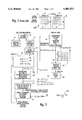
- FIG. 2 is a block diagram of the subject invention in which the subset is filled with candidate vectors in accordance with the subject distance determining formula and in accordance with a prediction algorithm which improves the performance of the testing procedure, and in which random number generation is improved through the utilization of random vector weight generation utilizing an importance factor;
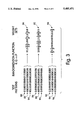
- FIG. 3 is a chart illustrating the main principle of weight calculation by test vector randomization
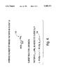
- FIG. 4 is a chart illustrating the algorithm of vector set partitioning
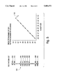
- FIG. 5 is a chart showing an example of vector or pattern coverage prediction and its use for vector set partitioning.
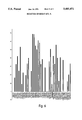
- FIG. 6 is a graph describing experimental results showing the advantage of presented system over the prior art.
- a set of tailored vectors suitable for the circuit is identified. These tailored vectors are subdivided into subsets 10 and 12, with each set including an initial vector 14 and subsequently added vectors 16 to fill up the subset. It is the purpose of the subsets to provide vectors appropriate for checking circuits having testing characteristics which require similar test signals. In order to do this, and as illustrated in FIG. 1, in the past vectors further and further from the initial vector were added until such time as the added vectors were too far away from the initial vector.
- the purpose of providing this subset of vectors is to calculate weights which go from an ideal set of weights for checking a particular fault to less and less ideal weights, until the process of adding vectors is stopped as illustrated by dotted line 18 when the added vectors are so far away from the initial vector, they are no longer useful.
- tailored vectors 20 are provided, with the tailored vectors being those which are appropriate for the particular circuit under test. Thereafter as illustrated at 21 for a given subset, S, a tailored vector is initially selected. Thereafter candidate vectors are extracted from the vector list, with the candidate vectors being entered as illustrated at 24 into a subset 26.
- the initial vector is 0 x 1 1.
- another vector, 1 x 1 x is added to this subset.
- V C here illustrated at 32 is appropriate to be added to this subset.
- the previous vectors are randomized as illustrated at 34 and weights are generated for these prior vectors in subset S.
- the rules for randomization and weight generation are as follows:
- the importance factor w i is calculated equal to the number of logic values in the vector that are not equal to a "don't care" value X. Then the weight for a given primary input j is equal to ##EQU2## where t ij is a logic value in position j of test vector i.
- the rule for determining distance is given as follows ##EQU3## where M is the number of bits in each test vector.
- Elementary distance d j is calculated as ##EQU4## where t j is a logical value in position j of the candidate vector d and w j is a weight calculated for i input j.
- the vector selected via unit 36 is that vector which has the smallest distance to the priorly entered vectors in the subset.
- these vectors are utilized in the generation of signals to be applied to a circuit under test.
- the vectors in the subset are randomized at 50 in accordance with the same formula used in 34.
- the calculated weights are to be applied to a random number generator 54 which then generates input signals and applies them to the circuit under test 56 so that it can be adequately tested.
- an importance factor is calculated for each vector or horizontal row of numbers.
- the rules for providing the importance factor, IF are as follows:
- Importance factor is calculated as a number of logical values in a horizontal row which are not equal to "X".
- the importance factor for the first vector 62 is "5" as calculated above.
- the importance factor for subsequent vectors 64, 66, 68, 70 and 72 are respectively "1".
- the Importance Factor for vector 62 at position 1 is 5
- the Importance Factor for vector 64 at position 0 is 1, yielding a weight 5/6. This is the weight to be applied to random generator 54 so that the generator will couple the appropriate signals to input #1 of the circuit under test.
- the result of a weight calculation for series of test patterns or vectors involves vectors 80, 82 and 84, which when combined, provides the weight set 86 generated in accordance with the above rules.
- the weight set corresponding to this set of vectors is illustrated at 92.
- vectors 92, 94 and 96 result in weights 98 as illustrated.
- M Q is defined as illustrated in FIG. 2 by equation 102.
- a pattern will be added to the subset Q in accordance with equation 104 of FIG. 4 which corresponds to equation 100 of FIG. 2.
- the number P N is in fact the predicted number of test patterns in the random sequence such that for a test pattern set 120 it can be seen that the subset is limited after the 33rd introduction of a candidate vector because the predicted number of test patterns in the random sequence decreases as illustrated at 122.
- the abscisa of this graph refers to the number of patterns or vectors in a given subset or partition, whereas the ordinate relates to the expected number of generated vectors appearing in a weighted random sequence.
- test pattern set is obtained through deterministic test vector generation.
- Each vector contains a logic value for each primary input of the circuit under test.
- Each value can be 1, 0, or X which indicates "don't care”.
- An example of a test pattern set is:
- Each weight set contains a weight for each primary input of the circuit under test.
- the weight is a probability of value "1" being applied at this input.
- subset selection one can start with an empty subset. Then one adds one pattern at a time to the subset, each time taking the "closest" one to those already selected.
- the ultimate goal is to have such a subset of test vectors that when represented with a set of weights and a corresponding random sequence in general, it will contain largest number of test patterns.
- patterns are added to the subset as long as the expected number of them in random sequence grows. The process is stopped as soon as the number starts falling.
- the distance of a pattern from a subset of other patterns is measured by the distance of this pattern from the weights set generated from this same subset.
- the importance factor is calculated for each pattern in a subset.
- This factor, IF is equal to the number of the logic values in this pattern that are not equal to X. Then to calculate weight for any given input of the circuit one adds all importance factors for patterns that have value "1" for this input. Then one adds all importance factors for patterns that have a value for this input not equal to X. Then one divides the first sum by the second.
- testing of digital circuits with randomly generated patterns of "1s" and "0s” for random testing purposes is considered to be an attractive alternative to deterministic methods using stored test patterns, each of which are used to detect a fault in the circuit such as a line stuck at either "0" or "1" regardless of the input signals to the corresponding device.
- Studies of such methods both in the external and the built-in test environment show several major advantages of random testing. Firstly, it allows significant compaction of test data which is especially important for built-in self-test. Secondly, random testing provides cost-effective means of increasing the coverage of faults not explicitly targeted during deterministic test generation.
- T (T 1 , T 2 , . . . T N ) be a set of N test vectors for a given circuit.
- Each vector T i consists of M values t ij ⁇ 0, 1, x ⁇ where x represents a "don't care" value.
- the set T has to be partitioned into the minimal number of subsets as shown in FIG. 1 such that with a given high probability, every member of each subset Q i ⁇ T will appear at least once in a sequence of no more than K patterns produced by a weighted random pattern generator with weights set P i calculated for each subset Q i .
- Q ⁇ T is a subset of test patterns.
- a fast partitioning procedure can be defined by a sequence of steps, each adding one pattern to the partition being formed as shown in FIG. 2.
- a randomization function P(Q) that calculates weights set P given a selected subset of test patterns Q.
- distance function D(Q,t) that calculates a measure of difference between test pattern t and a set of test patternsQ.
- distance function D(Q,t) is defined as a number of positions in which vector t has 1 (0) and at least one of the patterns in Q has 0 (1).
- Randomization function of above-mentioned article by F. Brglez et al. defines each individual weight P i ⁇ P as a ratio between the number of vectors in Q for which the value of bit i is 1 to the number of vectors for which this value is not x (a special "don't care" probability value X could be used in case when all patterns in Q have value x of bit i).
- Improved randomization and distance functions will be introduced below. However at this point only general meanings of randomization and distance are important for the definition of the partitioning algorithm.
- This function not only considers the values in D that contradict some of the values in Q but it also takes into account relative frequency of contradictions. In addition, if for two vectors distances calculated based on the contradictions with Q (left column of the Table VII) are the same, this function will give preference to the vector that turns fewer "don't care” components of P(Q) into the defined values (right column of the Table VII). This measure also defines the vector with the largest number of "don't care" values as a natural choice for the first iteration. To ensure this it is only necessary to define Q.sup.(0) as an empty set and p(Q.sup.(0)) as a vector consisting of values x.
- Randomization function P(Q) defined in J. Waicukauski, E. Lindbloom, E. Eichelberger, O. Forlenza. A Method for Generating Weighted Random Test Patterns. IBM Journal of Research and Development, vol. 33, No. 2, March 1989, pp. 149-161. provides a good approximation to the optimal distribution when vectors in the set Q contain few "don't care" values as is the case for vectors in Table VI. However, in practice, test vectors for scan circuits contain a significant number of "don't cares". Table VIII shows a somewhat extreme example of a test pattern set for which this randomization function of the WRP method J. Waicukauski. E. Lindbloom, E. Eichelberger, O. Forlenza. A Method for Generating Weighted Random Test Patterns. IBM Journal of Research and Development, vol. 33, No. 2, March 1989, pp. 149-161. produces results that are very far from optimal.
- a random binary signal with given probability p was calculated by arithmetic comparison of the state of LFSR with the value p*2 31 . After generating each random signal the state of LFSR was shifted 31 times in order to prevent dependency between consecutive random values. The same seed value of LFSR was used throughout all experiments, no reseeding was performed. In order to emulate possible hardware implementation more closely, values of weights were rounded to the nearest of the values 0, 2 -15 , 2 -14 , . . . , 1/2, . . . , 1-2 -15 , 1 (totalling 31 values so that a weight can be encoded by 5 bits). However this approximation did not alter the results significantly comparing to the non-rounded 31-bit binary representation of weights. Fault coverage was evaluated using a pattern-parallel fault simulator for combinational circuits.
- Table IX presents the results of experiments with weights calculation algorithm based on test pattern set randomization. Experiments were performed in the following way. Each circuit was first simulated with uniformly distributed random test patterns. Three runs were made for each circuit. During the first run uniform random test generation was stopped after 64 consecutive patterns did not detect any new fault. Then this number was increased to 512 and to 8192. After that tests for the remaining undetected faults were generated by a deterministic test pattern generator that was modified in order to prevent random specification of "don't care" input values.
- the procedure defined herein was used in order to produce new set of weights which in turn was simulated until the same number of unsuccessful trials as originally used in uniform random test generation (64, 512 or 8192) were reached. After that the deterministic test pattern set was simulated with the new reduced list of undetected faults, and unnecessary patterns were dropped. Then the next set of weights was calculated and the process repeated until no more test patterns were left. For comparison the weights calculation procedure of the WRP method J. Waieukauski, E. Lindbloom, E. Eichelberger, O. Forlenza. A Method for Generating Weighted Random Test Patterns. IBM Journal of Research and Development, vol. 33, No. 2, March 1989, pp. 149-161.
- Table IX correspond to circuit names, numbers of test patterns in original sets computed by deterministic test generator, and the resulting numbers of weight sets and random patterns obtained by proposed method and by the WRP method J. Waicukauski, E. Lindbloom, E. Eichelberger, O. Forlenza. A Method for Generating Weighted Random Test Patterns. IBM Journal of Research and Development, vol. 33, No. 2, March 1989, pp. 149-161.
Abstract
Description
              TABLE I
______________________________________
           0    x     1     1
           1    x     1     1
           1/2  ?     1     1
______________________________________
              TABLE II
______________________________________
          0    x     1     1
          1    x     1     1
          0    x     1     0
          1/3  ?     1     2/3
______________________________________
              TABLE III
______________________________________
          0    x     1     1
          1    x     1     1
          1    1     x     0
          2/3  1     1     2/3
______________________________________
              TABLE IV
______________________________________
1111111111111111
0111111111111111
1011111111111111
1101111111111111
100000xxxxxxx111
. . .
______________________________________
              TABLE V
______________________________________
1111111111111111
0000000000000000
______________________________________
j-R.sub.Q.spsb.(j) <j+1-R{Q.sup.(j), t.sub.k } (Equ. 6)
                                  TABLE VI
__________________________________________________________________________
Test Patterns for ANDOR Circuit
i  t.sub.i           i  t.sub.i           i  t.sub.i
__________________________________________________________________________
 1 11111111111111110111111111111111
                     23 00000000000000000000000000010000
                                          45 00000000000000001000000000000
                                             000
 2 00000000000000000000000010000000
                     24 11111111111111111111110111111111
                                          46 00000000000000000000000000001
                                             000
 3 00000000000100000000000000000000
                     25 00000000000010000000000000000000
                                          47 00000000000000000100000000000
                                             000
 4 11111111111111111111111111111111
                     26 11111111111110111111111111111111
                                          48 11111111111111111111110111111
                                             111
 5 11101111111111111111111111111111
                     27 11111111111111111111111111011111
                                          49 00000000100000000000000000000
                                             000
 6 00000000010000000000000000000000
                     28 00000000000000000000000100000000
                                          50 11111111111111111011111111111
                                             111
 7 00000000000000000000000000000000
                     29 11111111111101111111111111111111
                                          51 11111111111111111111111111110
                                             111
 8 00000000001000000000000000000000
                     30 00000000000000000000001000000000
                                          52 00000000000000000010000000000
                                             000
 9 00000000000000000000000000000001
                     31 01000000000000000000000000000000
                                          53 00000000000000000000000000000
                                             100
10 10000000000000000000000000000000
                     32 11111111111111111111101111111111
                                          54 00000000000000000001000000000
                                             000
11 11111111111111101111111111111111
                     33 00000000000001000000000000000000
                                          55 01111111111111111111111111111
                                             111
12 11111111111111111111111011111111
                     34 11111111111111111111011111111111
                                          56 11111111111111111101111111111
                                             111
13 11111111111111110111111111111111
                     35 10111111111111111111111111111111
                                          57 00000100000000000000000000000
                                             000
14 00000000000000000000000001000000
                     36 11111101111111111111111111111111
                                          58 11111111111111111110111111111
                                             111
15 11111111111111111111111111111011
                     37 00000000000000010000000000000000
                                          59 00000001000000000000000000000
                                             000
16 00001000000000000000000000000000
                     38 11011111111011111111111111111111
                                          60 00000000000000000000000000000
                                             010
17 00000000000000000000000000100000
                     39 11111011111111111111111111111111
                                          61 00000000000000000000100000000
                                             000
18 11111111111111111111111110111111
                     40 00100000000000000000000000000000
                                          62 11111111111111111111111111111
                                             110
19 00000010000000000000000000000000
                     41 00010000000000000000000000000000
                                          63 11111111111111111111111111101
                                             111
20 11110111111111111111111111111111
                     42 11111111110111111111111111111111
                                          64 11111111011111111111111111111
                                             111
21 11111111111111111111111111111101
                     43 00000000000000010000000000000000
                                          65 11111111101111111111111111111
                                             111
22 11111111111111111111111101111111
                     44 00000000000000000000010000000000
                                          66 11111111110111111111111111111
                                             111
__________________________________________________________________________
 Then formula (5) gives R.sub.Q(32) =0.83 and pattern t.sub.6 is the next
 candidate with distance 31 from Q.sup.(32). This pattern selection is a
 clear failure of the distance measure used here because even according to
 common sense t.sub.66 is a better choice. And in fact for Q.sup.(33)
 ={Q.sup.(32), t.sub.6 } R.sub.Q(32) ≈2.91 and according to (6)
 t.sub.6 should not be included into partition as the average number of
 generated test patterns goes down by 1.08. On the other hand for
 Q.sup.(33) ={Q.sup.(32), t.sub.66 } R.sub.Q(33) ≈0.96 and the
 average number of generated test patterns goes up by 0.87. After that
 whatever pattern than can be selected for the 34th iteration would not
 satisfy criterion (6) and partitioning would be stopped exactly where one
 would expect it to. In FIG. 5, the expected number of generated
 deterministic test patterns is plotted against the number of patterns
 included into the partition. The curve has a clear maximum when 33
 patterns are selected.
              TABLE VII
______________________________________
Distance Component Definition
            d.sub.j
t.sub.j       p.sub.j ε [0,1]
                        p.sub.j = X
______________________________________
0             M*p.sub.j 1
1             M*(1 - p.sub.j)
                        1
x             0         0
______________________________________
                                  TABLE VIII
__________________________________________________________________________
Example of Test Pattern Set with "Don't Care" Values
i  t.sub.i           i  t.sub.i           i  t.sub.i
__________________________________________________________________________
1  11111111111111111111111111111111
                     12 xxxxxxxxxx0xxxxxxxxxxxxxxxxxxxxx
                                          23 xxxxxxxxxxxxxxxxxxxxx0xxxxxxx
                                             xxx
2  0xxxxxxxxxxxxxxxxxxxxxxxxxxxxxxx
                     13 xxxxxxxxxxx0xxxxxxxxxxxxxxxxxxxx
                                          24 xxxxxxxxxxxxxxxxxxxxxx0xxxxxx
                                             xxx
3  x0xxxxxxxxxxxxxxxxxxxxxxxxxxxxxx
                     14 xxxxxxxxxxxx0xxxxxxxxxxxxxxxxxxx
                                          25 xxxxxxxxxxxxxxxxxxxxxxx0xxxxx
                                             xxx
4  xx0xxxxxxxxxxxxxxxxxxxxxxxxxxxxx
                     15 xxxxxxxxxxxxx0xxxxxxxxxxxxxxxxxx
                                          26 xxxxxxxxxxxxxxxxxxxxxxxx0xxxx
                                             xxx
5  xxx0xxxxxxxxxxxxxxxxxxxxxxxxxxxx
                     16 xxxxxxxxxxxxxx0xxxxxxxxxxxxxxxxx
                                          27 xxxxxxxxxxxxxxxxxxxxxxxxx0xxx
                                             xxx
6  xxxx0xxxxxxxxxxxxxxxxxxxxxxxxxxx
                     17 xxxxxxxxxxxxxxx0xxxxxxxxxxxxxxxx
                                          28 xxxxxxxxxxxxxxxxxxxxxxxxxx0xx
                                             xxx
7  xxxxx0xxxxxxxxxxxxxxxxxxxxxxxxxx
                     18 xxxxxxxxxxxxxxxx0xxxxxxxxxxxxxxx
                                          29 xxxxxxxxxxxxxxxxxxxxxxxxxxx0x
                                             xxx
8  xxxxxx0xxxxxxxxxxxxxxxxxxxxxxxxx
                     19 xxxxxxxxxxxxxxxxxx0xxxxxxxxxxxxx
                                          30 xxxxxxxxxxxxxxxxxxxxxxxxxxxx0
                                             xxx
9  xxxxxxx0xxxxxxxxxxxxxxxxxxxxxxxx
                     20 xxxxxxxxxxxxxxxxxxx0xxxxxxxxxxxx
                                          31 xxxxxxxxxxxxxxxxxxxxxxxxxxxxx
                                             0xx
10 xxxxxxxx0xxxxxxxxxxxxxxxxxxxxxxx
                     21 xxxxxxxxxxxxxxxxxxxx0xxxxxxxxxxx
                                          32 xxxxxxxxxxxxxxxxxxxxxxxxxxxxx
                                             x0x
11 xxxxxxxxx0xxxxxxxxxxxxxxxxxxxxxx
                     22 xxxxxxxxxxxxxxxxxxxxx0xxxxxxxxxx
                                          33 xxxxxxxxxxxxxxxxxxxxxxxxxxxxx
                                             xx0
__________________________________________________________________________
                                  TABLE IX
__________________________________________________________________________
Experimental Results of Weights Calculation Method
Based on Test Patterns Randomization
         Proposed Method
                  WRP Method [5]    Proposed Method
                                             WRP Method [5]
    DTG  Weight
              Test
                  Weight
                       Test    DTG  Weight
                                         Test
                                             Weight
                                                  Test
Circuit
    Patterns
         Sets Length
                  Sets Length
                           Circuit
                               Patterns
                                    Sets Length
                                             Sets Length
__________________________________________________________________________
c880
    31   3    465 3    563 s1196c
                               64   10   2002
                                             13   1972
c1908
    41   10   1253
                  12   1430
                           s1196c
                               20   5    6424
                                             7    6051
c2670
    91   9    1360
                  12   1979
                           s1238c
                               67   9    2460
                                             14   2110
c2670
    85   4    4034
                  7    7886
                           s1238c
                               18   5    8559
                                             6    7692
c2670
    81   3    12593
                  4    42437
                           s1423c
                               33   5    620 5    725
c3540
    95   5    1298
                  7    1673
                           s5378c
                               175  7    2270
                                             11   2692
c7552
    151  12   2072
                  12   2451
                           s5378c
                               30   4    11005
                                             6    10760
c7552
    137  8    4885
                  9    11012
                           s9234c
                               637  11   3368
                                             17   4589
c7552
    78   5    69495
                  5    79086
                           s9234c
                               365  8    16391
                                             13   20720
s420c
    46   4    532 5    782 s9234c
                               96   4    160977
                                             6    169169
s420c
    28   2    1825
                  3    3065
                           s13207c
                               838  7    3430
                                             9    4935
s526c
    26   3    643 5    781 s13207c
                               290  4    15781
                                             5    19429
s641c
    29   3    593 3    697 s15850c
                               438  6    3051
                                             8    3771
s713c
    26   3    576 4    545 s15850c
                               217  4    14767
                                             5    16273
s820c
    52   5    1287
                  6    1503
                           s15850c
                               110  3    141181
                                             3    146548
s832c
    52   4    1271
                  6    1499
                           s38417c
                               1489 8    4972
                                             11   8584
s838c
    86   5    893 9    1341
                           s38417c
                               783  6    30663
                                             6    41063
s838c
    70   3    3916
                  6    5089
                           s38417c
                               273  3    277109
                                             4    304265
s838c
    64   2    17484
                  5    28917
                           s38584c
                               596  7    5381
                                             9    6135
s953c
    81   4    973 7    1061
                           s38584c
                               186  5    19973
                                             5    22354
s953c
    21   2    3870
                  3    4227
                           s38584c
                               33   2    107208
                                             3    118245
__________________________________________________________________________
Claims (9)
w=(ΣIF.sub.1)/(ΣIF.sub.1,0)
Priority Applications (1)
| Application Number | Priority Date | Filing Date | Title |
|---|---|---|---|
| US08/138,135 US5485471A (en) | 1993-10-15 | 1993-10-15 | System for testing of digital integrated circuits |
Applications Claiming Priority (1)
| Application Number | Priority Date | Filing Date | Title |
|---|---|---|---|
| US08/138,135 US5485471A (en) | 1993-10-15 | 1993-10-15 | System for testing of digital integrated circuits |
Publications (1)
| Publication Number | Publication Date |
|---|---|
| US5485471A true US5485471A (en) | 1996-01-16 |
Family
ID=22480577
Family Applications (1)
| Application Number | Title | Priority Date | Filing Date |
|---|---|---|---|
| US08/138,135 Expired - Lifetime US5485471A (en) | 1993-10-15 | 1993-10-15 | System for testing of digital integrated circuits |
Country Status (1)
| Country | Link |
|---|---|
| US (1) | US5485471A (en) |
Cited By (33)
| Publication number | Priority date | Publication date | Assignee | Title |
|---|---|---|---|---|
| US5649165A (en) * | 1995-01-31 | 1997-07-15 | Fujitsu Limited | Topology-based computer-aided design system for digital circuits and method thereof |
| US5680518A (en) * | 1994-08-26 | 1997-10-21 | Hangartner; Ricky D. | Probabilistic computing methods and apparatus |
| WO1998044357A1 (en) * | 1997-03-31 | 1998-10-08 | Intel Corporation | A method for application of weighted random patterns to partial scan designs |
| US5831998A (en) * | 1996-12-13 | 1998-11-03 | Northern Telecom Limited | Method of testcase optimization |
| US5835891A (en) * | 1997-02-06 | 1998-11-10 | Hewlett-Packard Company | Device modeling using non-parametric statistical determination of boundary data vectors |
| US5859962A (en) * | 1995-12-21 | 1999-01-12 | Ncr Corporation | Automated verification of digital design |
| US5922079A (en) * | 1996-03-08 | 1999-07-13 | Hewlett-Packard Company | Automated analysis of a model based diagnostic system |
| US5930149A (en) * | 1994-09-30 | 1999-07-27 | Ricoh Company, Ltd. | Test-vector editing system and method |
| US5983380A (en) * | 1997-09-16 | 1999-11-09 | International Business Machines Corporation | Weighted random pattern built-in self-test |
| US6061818A (en) * | 1997-05-08 | 2000-05-09 | The Board Of Trustees Of The Leland Stanford Junior University | Altering bit sequences to contain predetermined patterns |
| US6212669B1 (en) | 1997-11-05 | 2001-04-03 | Fujitsu Limited | Method for verifying and representing hardware by decomposition and partitioning |
| US6223316B1 (en) * | 1998-05-27 | 2001-04-24 | Nec Usa, Inc. | Vector restoration using accelerated validation and refinement |
| US6314540B1 (en) * | 1999-04-12 | 2001-11-06 | International Business Machines Corporation | Partitioned pseudo-random logic test for improved manufacturability of semiconductor chips |
| US20020062462A1 (en) * | 2000-09-22 | 2002-05-23 | Fujitsu Limited | Processor |
| US20020120897A1 (en) * | 2001-02-28 | 2002-08-29 | Eby David H. | Test generator having a poisson distribution error signal |
| US20030188273A1 (en) * | 2002-03-28 | 2003-10-02 | Intel Corporation | Simulation-based technique for contention avoidance in automatic test pattern generation |
| US20030229834A1 (en) * | 2002-06-11 | 2003-12-11 | On-Chip Technologies, Inc. | Variable clocked scan test circuitry and method |
| US6678853B1 (en) * | 1999-12-17 | 2004-01-13 | Hewlett-Packard Development Company, L.P. | Method and apparatus for generating random code |
| US20040009616A1 (en) * | 2002-07-09 | 2004-01-15 | International Business Machines Corporation | Method to detect systematic defects in VLSI manufacturing |
| US20040078677A1 (en) * | 2002-10-21 | 2004-04-22 | Sun Microsystems, Inc. | Method for microprocessor test insertion reduction |
| US6865706B1 (en) * | 2000-06-07 | 2005-03-08 | Agilent Technologies, Inc. | Apparatus and method for generating a set of test vectors using nonrandom filling |
| US20050235177A1 (en) * | 2004-04-20 | 2005-10-20 | Matsushita Electric Industrial Co., Ltd. | Path delay test method |
| KR100520629B1 (en) * | 1997-06-26 | 2005-12-21 | 애질런트 테크놀로지스, 인크. | Model-based diagnostic system with automated procedures for text test selection |
| US20060005094A1 (en) * | 2004-06-22 | 2006-01-05 | Yasuyuki Nozuyama | Test pattern generating apparatus, method for automatically generating test patterns and computer program product for executing an application for a test pattern generating apparatus |
| US7103816B2 (en) * | 2001-01-23 | 2006-09-05 | Cadence Design Systems, Inc. | Method and system for reducing test data volume in the testing of logic products |
| US20070055665A1 (en) * | 2005-08-01 | 2007-03-08 | Youichi Kitahara | Sequential pattern extracting apparatus |
| US20080010531A1 (en) * | 2006-06-12 | 2008-01-10 | Mks Instruments, Inc. | Classifying faults associated with a manufacturing process |
| US20090037013A1 (en) * | 2007-05-02 | 2009-02-05 | Mks Instruments, Inc. | Automated Model Building and Model Updating |
| US20100057237A1 (en) * | 2008-09-02 | 2010-03-04 | Mks Instruments, Inc. | Automated model building and batch model building for a manufacturing process, process monitoring, and fault detection |
| US20100191361A1 (en) * | 2009-01-23 | 2010-07-29 | Mks Instruments, Inc. | Controlling a Manufacturing Process with a Multivariate Model |
| CN103344907A (en) * | 2013-07-02 | 2013-10-09 | 上海大学 | Pseudorandom low-power dissipation test method based on distances between test codes |
| CN110058133A (en) * | 2019-04-15 | 2019-07-26 | 杭州拓深科技有限公司 | A kind of electrical circuit fault electric arc wrong report optimization method based on feedback mechanism |
| US20190318135A1 (en) * | 2018-04-11 | 2019-10-17 | Nxp B.V. | Method for triggering and detecting a malicious circuit in an integrated circuit device |
Citations (5)
| Publication number | Priority date | Publication date | Assignee | Title |
|---|---|---|---|---|
| US4688223A (en) * | 1985-06-24 | 1987-08-18 | International Business Machines Corporation | Weighted random pattern testing apparatus and method |
| US5027353A (en) * | 1989-04-17 | 1991-06-25 | At&T Bell Laboratories | Method for testing interconnections |
| US5187712A (en) * | 1990-02-26 | 1993-02-16 | At&T Bell Laboratories | Pseudo-exhaustive self-test technique |
| US5323400A (en) * | 1991-09-09 | 1994-06-21 | Northern Telecom Limited | Scan cell for weighted random pattern generation and method for its operation |
| US5414716A (en) * | 1993-09-22 | 1995-05-09 | Mitsubishi Electronic Research Laboratories, Inc. | Weighting system for testing of circuits utilizing determination of undetected faults |
-
1993
- 1993-10-15 US US08/138,135 patent/US5485471A/en not_active Expired - Lifetime
Patent Citations (5)
| Publication number | Priority date | Publication date | Assignee | Title |
|---|---|---|---|---|
| US4688223A (en) * | 1985-06-24 | 1987-08-18 | International Business Machines Corporation | Weighted random pattern testing apparatus and method |
| US5027353A (en) * | 1989-04-17 | 1991-06-25 | At&T Bell Laboratories | Method for testing interconnections |
| US5187712A (en) * | 1990-02-26 | 1993-02-16 | At&T Bell Laboratories | Pseudo-exhaustive self-test technique |
| US5323400A (en) * | 1991-09-09 | 1994-06-21 | Northern Telecom Limited | Scan cell for weighted random pattern generation and method for its operation |
| US5414716A (en) * | 1993-09-22 | 1995-05-09 | Mitsubishi Electronic Research Laboratories, Inc. | Weighting system for testing of circuits utilizing determination of undetected faults |
Cited By (53)
| Publication number | Priority date | Publication date | Assignee | Title |
|---|---|---|---|---|
| US5680518A (en) * | 1994-08-26 | 1997-10-21 | Hangartner; Ricky D. | Probabilistic computing methods and apparatus |
| US5930149A (en) * | 1994-09-30 | 1999-07-27 | Ricoh Company, Ltd. | Test-vector editing system and method |
| US5649165A (en) * | 1995-01-31 | 1997-07-15 | Fujitsu Limited | Topology-based computer-aided design system for digital circuits and method thereof |
| US5859962A (en) * | 1995-12-21 | 1999-01-12 | Ncr Corporation | Automated verification of digital design |
| US5922079A (en) * | 1996-03-08 | 1999-07-13 | Hewlett-Packard Company | Automated analysis of a model based diagnostic system |
| US5831998A (en) * | 1996-12-13 | 1998-11-03 | Northern Telecom Limited | Method of testcase optimization |
| US5835891A (en) * | 1997-02-06 | 1998-11-10 | Hewlett-Packard Company | Device modeling using non-parametric statistical determination of boundary data vectors |
| EP1015899A4 (en) * | 1997-03-31 | 2002-11-13 | Intel Corp | A method for application of weighted random patterns to partial scan designs |
| US5968194A (en) * | 1997-03-31 | 1999-10-19 | Intel Corporation | Method for application of weighted random patterns to partial scan designs |
| EP1015899A1 (en) * | 1997-03-31 | 2000-07-05 | Intel Corporation | A method for application of weighted random patterns to partial scan designs |
| WO1998044357A1 (en) * | 1997-03-31 | 1998-10-08 | Intel Corporation | A method for application of weighted random patterns to partial scan designs |
| US6061818A (en) * | 1997-05-08 | 2000-05-09 | The Board Of Trustees Of The Leland Stanford Junior University | Altering bit sequences to contain predetermined patterns |
| KR100520629B1 (en) * | 1997-06-26 | 2005-12-21 | 애질런트 테크놀로지스, 인크. | Model-based diagnostic system with automated procedures for text test selection |
| US5983380A (en) * | 1997-09-16 | 1999-11-09 | International Business Machines Corporation | Weighted random pattern built-in self-test |
| US6212669B1 (en) | 1997-11-05 | 2001-04-03 | Fujitsu Limited | Method for verifying and representing hardware by decomposition and partitioning |
| US7673263B2 (en) | 1997-11-05 | 2010-03-02 | Fujitsu Limited | Method for verifying and representing hardware by decomposition and partitioning |
| US6560758B1 (en) | 1997-11-05 | 2003-05-06 | Fujitsu Limited | Method for verifying and representing hardware by decomposition and partitioning |
| US7028278B2 (en) | 1997-11-05 | 2006-04-11 | Fujitsu Limited | Method of verifying and representing hardware by decomposition and partitioning |
| US20040015799A1 (en) * | 1997-11-05 | 2004-01-22 | Fujitsu Limited | Method of verifying and representing hardware by decomposition and partitioning |
| US6223316B1 (en) * | 1998-05-27 | 2001-04-24 | Nec Usa, Inc. | Vector restoration using accelerated validation and refinement |
| US6314540B1 (en) * | 1999-04-12 | 2001-11-06 | International Business Machines Corporation | Partitioned pseudo-random logic test for improved manufacturability of semiconductor chips |
| US6678853B1 (en) * | 1999-12-17 | 2004-01-13 | Hewlett-Packard Development Company, L.P. | Method and apparatus for generating random code |
| US6865706B1 (en) * | 2000-06-07 | 2005-03-08 | Agilent Technologies, Inc. | Apparatus and method for generating a set of test vectors using nonrandom filling |
| US20020062462A1 (en) * | 2000-09-22 | 2002-05-23 | Fujitsu Limited | Processor |
| US6721905B2 (en) * | 2000-09-22 | 2004-04-13 | Fujitsu Limited | Processor |
| US7103816B2 (en) * | 2001-01-23 | 2006-09-05 | Cadence Design Systems, Inc. | Method and system for reducing test data volume in the testing of logic products |
| US6816992B2 (en) * | 2001-02-28 | 2004-11-09 | Tektronix, Inc. | Test generator having a poisson distribution error signal |
| US20020120897A1 (en) * | 2001-02-28 | 2002-08-29 | Eby David H. | Test generator having a poisson distribution error signal |
| US20030188273A1 (en) * | 2002-03-28 | 2003-10-02 | Intel Corporation | Simulation-based technique for contention avoidance in automatic test pattern generation |
| US20030229834A1 (en) * | 2002-06-11 | 2003-12-11 | On-Chip Technologies, Inc. | Variable clocked scan test circuitry and method |
| USRE41187E1 (en) * | 2002-06-11 | 2010-03-30 | Cooke Laurence H | Variable clocked scan test circuitry and method |
| US7234092B2 (en) * | 2002-06-11 | 2007-06-19 | On-Chip Technologies, Inc. | Variable clocked scan test circuitry and method |
| US6880136B2 (en) | 2002-07-09 | 2005-04-12 | International Business Machines Corporation | Method to detect systematic defects in VLSI manufacturing |
| US20040009616A1 (en) * | 2002-07-09 | 2004-01-15 | International Business Machines Corporation | Method to detect systematic defects in VLSI manufacturing |
| US20040078677A1 (en) * | 2002-10-21 | 2004-04-22 | Sun Microsystems, Inc. | Method for microprocessor test insertion reduction |
| US7010734B2 (en) * | 2002-10-21 | 2006-03-07 | Sun Microsystems, Inc. | Method for microprocessor test insertion reduction |
| US20050235177A1 (en) * | 2004-04-20 | 2005-10-20 | Matsushita Electric Industrial Co., Ltd. | Path delay test method |
| US20060005094A1 (en) * | 2004-06-22 | 2006-01-05 | Yasuyuki Nozuyama | Test pattern generating apparatus, method for automatically generating test patterns and computer program product for executing an application for a test pattern generating apparatus |
| US7406645B2 (en) * | 2004-06-22 | 2008-07-29 | Kabushiki Kaisha Toshiba | Test pattern generating apparatus, method for automatically generating test patterns and computer program product for executing an application for a test pattern generating apparatus |
| US7458001B2 (en) * | 2005-08-01 | 2008-11-25 | Kabushiki Kaisha Toshiba | Sequential pattern extracting apparatus |
| US20070055665A1 (en) * | 2005-08-01 | 2007-03-08 | Youichi Kitahara | Sequential pattern extracting apparatus |
| US20090132531A1 (en) * | 2005-08-01 | 2009-05-21 | Kabushiki Kaisha Toshiba | Sequential pattern extracting apparatus |
| US20080010531A1 (en) * | 2006-06-12 | 2008-01-10 | Mks Instruments, Inc. | Classifying faults associated with a manufacturing process |
| US20090037013A1 (en) * | 2007-05-02 | 2009-02-05 | Mks Instruments, Inc. | Automated Model Building and Model Updating |
| US8494798B2 (en) | 2008-09-02 | 2013-07-23 | Mks Instruments, Inc. | Automated model building and batch model building for a manufacturing process, process monitoring, and fault detection |
| US20100057237A1 (en) * | 2008-09-02 | 2010-03-04 | Mks Instruments, Inc. | Automated model building and batch model building for a manufacturing process, process monitoring, and fault detection |
| US20100191361A1 (en) * | 2009-01-23 | 2010-07-29 | Mks Instruments, Inc. | Controlling a Manufacturing Process with a Multivariate Model |
| US9069345B2 (en) | 2009-01-23 | 2015-06-30 | Mks Instruments, Inc. | Controlling a manufacturing process with a multivariate model |
| CN103344907A (en) * | 2013-07-02 | 2013-10-09 | 上海大学 | Pseudorandom low-power dissipation test method based on distances between test codes |
| US20190318135A1 (en) * | 2018-04-11 | 2019-10-17 | Nxp B.V. | Method for triggering and detecting a malicious circuit in an integrated circuit device |
| US11023623B2 (en) * | 2018-04-11 | 2021-06-01 | Nxp B.V. | Method for triggering and detecting a malicious circuit in an integrated circuit device |
| CN110058133A (en) * | 2019-04-15 | 2019-07-26 | 杭州拓深科技有限公司 | A kind of electrical circuit fault electric arc wrong report optimization method based on feedback mechanism |
| CN110058133B (en) * | 2019-04-15 | 2021-03-02 | 杭州拓深科技有限公司 | Feedback mechanism-based electric circuit fault arc false alarm optimization method |
Similar Documents
| Publication | Publication Date | Title |
|---|---|---|
| US5485471A (en) | System for testing of digital integrated circuits | |
| US5414716A (en) | Weighting system for testing of circuits utilizing determination of undetected faults | |
| US7610539B2 (en) | Method and apparatus for testing logic circuit designs | |
| JP2554410B2 (en) | Test pattern bit sequence generation circuit and method for testing digital circuit device | |
| US6070261A (en) | Multi-phase test point insertion for built-in self test of integrated circuits | |
| Tamarapalli et al. | Constructive multi-phase test point insertion for scan-based BIST | |
| Bershteyn | Calculation of multiple sets of weights for weighted random testing | |
| Touba et al. | Bit-fixing in pseudorandom sequences for scan BIST | |
| US5377197A (en) | Method for automatically generating test vectors for digital integrated circuits | |
| Rudnick et al. | A genetic algorithm framework for test generation | |
| US6256759B1 (en) | Hybrid algorithm for test point selection for scan-based BIST | |
| Snethen | Simulator-oriented fault test generator | |
| US5479414A (en) | Look ahead pattern generation and simulation including support for parallel fault simulation in LSSD/VLSI logic circuit testing | |
| US5726996A (en) | Process for dynamic composition and test cycles reduction | |
| Jas et al. | Weighted pseudorandom hybrid BIST | |
| US20060236186A1 (en) | Test Output Compaction with Improved Blocking of Unknown Values | |
| Kundu et al. | A small test generator for large designs | |
| Chatterjee et al. | A BIST pattern generator design for near-perfect fault coverage | |
| Corno et al. | GARDA: A diagnostic ATPG for large synchronous sequential circuits | |
| Ashaibi et al. | Fixed-biased pseudorandom built-in self-test for random pattern resistant circuits | |
| Fagot et al. | On using machine learning for logic BIST | |
| Li et al. | On test generation for transition faults with minimized peak power dissipation | |
| US20040088626A1 (en) | Method and apparatus for determining optimum initial value for test pattern generator | |
| Neebel et al. | Inhomogeneous cellular automata for weighted random pattern generation | |
| Kalligeros et al. | Reseeding-based test set embedding with reduced test sequences |
Legal Events
| Date | Code | Title | Description |
|---|---|---|---|
| AS | Assignment |
Owner name: MITSUBISHI ELECTRIC RESEARCH LABORATORIES, INC., M Free format text: ASSIGNMENT OF ASSIGNORS INTEREST;ASSIGNOR:BERSHTEYN, MIKHAIL;REEL/FRAME:006739/0687 Effective date: 19931013 |
|
| STCF | Information on status: patent grant |
Free format text: PATENTED CASE |
|
| AS | Assignment |
Owner name: MITSUBISHI ELECTRIC INFORMATION TECHNOLOGY CENTER Free format text: CHANGE OF NAME;ASSIGNOR:MITSUBISHI ELECTRIC RESEARCH LABORATORIES, INC.;REEL/FRAME:008186/0570 Effective date: 19960424 |
|
| FPAY | Fee payment |
Year of fee payment: 4 |
|
| AS | Assignment |
Owner name: MITSUBISHI ELECTRIC RESEARCH LABORATORIES, INC., M Free format text: CHANGE OF NAME;ASSIGNOR:MITSUBISHI ELECTRIC INFORMATION TECHNOLOGY CENTER AMERICA, INC.;REEL/FRAME:011564/0329 Effective date: 20000828 |
|
| FPAY | Fee payment |
Year of fee payment: 8 |
|
| FPAY | Fee payment |
Year of fee payment: 12 |