US5488419A - Video compression coding and decoding with automatic sub-pixel frame/field motion compensation - Google Patents
Video compression coding and decoding with automatic sub-pixel frame/field motion compensation Download PDFInfo
- Publication number
- US5488419A US5488419A US08/031,495 US3149593A US5488419A US 5488419 A US5488419 A US 5488419A US 3149593 A US3149593 A US 3149593A US 5488419 A US5488419 A US 5488419A
- Authority
- US
- United States
- Prior art keywords
- block
- frame
- interpolation process
- coded
- based interpolation
- Prior art date
- Legal status (The legal status is an assumption and is not a legal conclusion. Google has not performed a legal analysis and makes no representation as to the accuracy of the status listed.)
- Expired - Fee Related
Links
- 230000033001 locomotion Effects 0.000 title claims abstract description 173
- 230000006835 compression Effects 0.000 title claims description 11
- 238000007906 compression Methods 0.000 title claims description 11
- 239000013598 vector Substances 0.000 claims abstract description 99
- 238000000034 method Methods 0.000 claims description 99
- 230000008569 process Effects 0.000 claims description 64
- 238000001514 detection method Methods 0.000 claims description 13
- 238000005070 sampling Methods 0.000 claims description 9
- 230000001131 transforming effect Effects 0.000 claims 8
- 238000000638 solvent extraction Methods 0.000 claims 4
- 238000013139 quantization Methods 0.000 description 21
- 238000010586 diagram Methods 0.000 description 5
- 230000000694 effects Effects 0.000 description 3
- 230000002441 reversible effect Effects 0.000 description 3
- 230000002123 temporal effect Effects 0.000 description 3
- 230000009466 transformation Effects 0.000 description 3
- 230000006978 adaptation Effects 0.000 description 2
- 239000011159 matrix material Substances 0.000 description 2
- 230000000750 progressive effect Effects 0.000 description 2
- 230000009467 reduction Effects 0.000 description 2
- 238000004088 simulation Methods 0.000 description 2
- 230000003044 adaptive effect Effects 0.000 description 1
- 230000005540 biological transmission Effects 0.000 description 1
- 230000006870 function Effects 0.000 description 1
- 230000008520 organization Effects 0.000 description 1
- 238000005192 partition Methods 0.000 description 1
Images


Classifications
-
- H—ELECTRICITY
- H04—ELECTRIC COMMUNICATION TECHNIQUE
- H04N—PICTORIAL COMMUNICATION, e.g. TELEVISION
- H04N5/00—Details of television systems
- H04N5/14—Picture signal circuitry for video frequency region
- H04N5/144—Movement detection
- H04N5/145—Movement estimation
-
- H—ELECTRICITY
- H04—ELECTRIC COMMUNICATION TECHNIQUE
- H04N—PICTORIAL COMMUNICATION, e.g. TELEVISION
- H04N19/00—Methods or arrangements for coding, decoding, compressing or decompressing digital video signals
- H04N19/10—Methods or arrangements for coding, decoding, compressing or decompressing digital video signals using adaptive coding
- H04N19/102—Methods or arrangements for coding, decoding, compressing or decompressing digital video signals using adaptive coding characterised by the element, parameter or selection affected or controlled by the adaptive coding
- H04N19/103—Selection of coding mode or of prediction mode
- H04N19/105—Selection of the reference unit for prediction within a chosen coding or prediction mode, e.g. adaptive choice of position and number of pixels used for prediction
-
- H—ELECTRICITY
- H04—ELECTRIC COMMUNICATION TECHNIQUE
- H04N—PICTORIAL COMMUNICATION, e.g. TELEVISION
- H04N19/00—Methods or arrangements for coding, decoding, compressing or decompressing digital video signals
- H04N19/10—Methods or arrangements for coding, decoding, compressing or decompressing digital video signals using adaptive coding
- H04N19/102—Methods or arrangements for coding, decoding, compressing or decompressing digital video signals using adaptive coding characterised by the element, parameter or selection affected or controlled by the adaptive coding
- H04N19/103—Selection of coding mode or of prediction mode
- H04N19/112—Selection of coding mode or of prediction mode according to a given display mode, e.g. for interlaced or progressive display mode
-
- H—ELECTRICITY
- H04—ELECTRIC COMMUNICATION TECHNIQUE
- H04N—PICTORIAL COMMUNICATION, e.g. TELEVISION
- H04N19/00—Methods or arrangements for coding, decoding, compressing or decompressing digital video signals
- H04N19/10—Methods or arrangements for coding, decoding, compressing or decompressing digital video signals using adaptive coding
- H04N19/134—Methods or arrangements for coding, decoding, compressing or decompressing digital video signals using adaptive coding characterised by the element, parameter or criterion affecting or controlling the adaptive coding
- H04N19/136—Incoming video signal characteristics or properties
- H04N19/137—Motion inside a coding unit, e.g. average field, frame or block difference
-
- H—ELECTRICITY
- H04—ELECTRIC COMMUNICATION TECHNIQUE
- H04N—PICTORIAL COMMUNICATION, e.g. TELEVISION
- H04N19/00—Methods or arrangements for coding, decoding, compressing or decompressing digital video signals
- H04N19/10—Methods or arrangements for coding, decoding, compressing or decompressing digital video signals using adaptive coding
- H04N19/134—Methods or arrangements for coding, decoding, compressing or decompressing digital video signals using adaptive coding characterised by the element, parameter or criterion affecting or controlling the adaptive coding
- H04N19/157—Assigned coding mode, i.e. the coding mode being predefined or preselected to be further used for selection of another element or parameter
- H04N19/16—Assigned coding mode, i.e. the coding mode being predefined or preselected to be further used for selection of another element or parameter for a given display mode, e.g. for interlaced or progressive display mode
-
- H—ELECTRICITY
- H04—ELECTRIC COMMUNICATION TECHNIQUE
- H04N—PICTORIAL COMMUNICATION, e.g. TELEVISION
- H04N19/00—Methods or arrangements for coding, decoding, compressing or decompressing digital video signals
- H04N19/50—Methods or arrangements for coding, decoding, compressing or decompressing digital video signals using predictive coding
- H04N19/503—Methods or arrangements for coding, decoding, compressing or decompressing digital video signals using predictive coding involving temporal prediction
- H04N19/51—Motion estimation or motion compensation
- H04N19/523—Motion estimation or motion compensation with sub-pixel accuracy
-
- H—ELECTRICITY
- H04—ELECTRIC COMMUNICATION TECHNIQUE
- H04N—PICTORIAL COMMUNICATION, e.g. TELEVISION
- H04N19/00—Methods or arrangements for coding, decoding, compressing or decompressing digital video signals
- H04N19/50—Methods or arrangements for coding, decoding, compressing or decompressing digital video signals using predictive coding
- H04N19/503—Methods or arrangements for coding, decoding, compressing or decompressing digital video signals using predictive coding involving temporal prediction
- H04N19/51—Motion estimation or motion compensation
- H04N19/577—Motion compensation with bidirectional frame interpolation, i.e. using B-pictures
-
- H—ELECTRICITY
- H04—ELECTRIC COMMUNICATION TECHNIQUE
- H04N—PICTORIAL COMMUNICATION, e.g. TELEVISION
- H04N19/00—Methods or arrangements for coding, decoding, compressing or decompressing digital video signals
- H04N19/60—Methods or arrangements for coding, decoding, compressing or decompressing digital video signals using transform coding
- H04N19/61—Methods or arrangements for coding, decoding, compressing or decompressing digital video signals using transform coding in combination with predictive coding
Definitions
- This invention relates to compression coding and decoding of high quality interlaced scan video signals for digital storage and transmission media.
- video sequences can be classified into two types: the progressive scan video sequence and the interlaced scan video sequence.
- a progressive scan video sequence a frame in the sequence is captured and refreshed sequentially line by line from the top to bottom of the frame.
- an interlaced scan video sequence a frame consists of two fields, the even field made up of the even lines of the frame and the odd field made up of the odd lines of the frame. Capturing and refreshing are performed first on the even field, sequentially from the top to bottom of the field, and followed by the odd field in the same manner. Since a large number of the present sequence sources are in the interlaced scan format (e.g. NTSC, PAL), an increasing number of research efforts have been directed towards the efficient coding of the interlaced scan video sequence.
- the interlaced scan format e.g. NTSC, PAL
- Video bandwidth compression is done by reducing the temporal, spatial and statistical redundancy in a video sequence.
- motion estimation and compensation is used.
- the frames which can also be referred to as pictures, in an interlaced scan video sequence can be classified into two types: (1) intra-coded frames in which each frame is coded using information only from itself; (2) predictive-coded frames in which each frame is coded using motion compensated prediction from a past intra-coded or predictive-coded frame or/and a future intra-coded or predictive-coded frame.
- Each frame in the sequence is first partitioned into blocks of pixel data which are then processed by a block coding method such as discrete cosine transform (DCT) with or without motion compensation.
- a block coding method such as discrete cosine transform (DCT) with or without motion compensation.
- the blocks are coded with motion compensation using information from an adjacent frame by block matching motion estimation and compensation to predict the contents of the coded frame.
- the block matching algorithm used consists of determining the direction of translatory motion of the blocks of pixels from one frame to the next by finding the best matching block based on some pre-determined criteria. The differences between the best matching block and the actual block of pixels are then subjected to transformation (e.g.
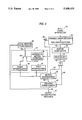
- FIG. 1 is a block diagram describing the method proposed by MPEG. Detailed description of the method can be found in the document "MPEG Video Simulation Model Three (SM3)", ISO-IEC/JTC1/SC2/WG8, MPEG 90/041, 1990.
- SM3 MPEG Video Simulation Model Three
- each block of pixels has an associated motion vector to indicate the location of the best matching block in the adjacent frame.
- the motion vector is a pair of numbers indicating the x and y offset of the block's location in the adjacent frame, with reference to the current block's location. For example, a motion vector of (3, 2) means that the best match for the current block can be found in the adjacent frames at the location +3 pixel to the right and +2 pixel below the current block's location. If all the motion vectors used for motion compensation are integer values, the motion vectors are called full-pixel resolution motion vectors, and the searching process for these full-pixel resolution motion vectors is called full-pixel search.
- a sub-pixel resolution motion vector may be obtained.
- the sub-pixel resolution motion vector has non-integer values and points to a location in between the full-pixel location.
- the block to be used for compensation is then interpolated by using the pixels around it.
- One common example of the sub-pixel resolution motion vector is the half-pixel resolution motion vector.
- the half-pixel resolution motion vector may have values ⁇ 0.5, ⁇ 1.5, ⁇ 2.5, . . .
- the search for the half-pixel resolution motion vector usually follows after the full-pixel search such that the half-pixel is searched around the location indicated by the full-pixel resolution motion vector.
- the half-pixel resolution motion vector indicates that the best matching block of the adjacent frame comes from a half-pixel resolution block.
- This half-pixel resolution block can be obtained from the adjacent frame in two different ways, considering the interlace structure of the sequence, resulting in a frame-based interpolation mode and a field-based interpolation mode.
- FIG. 2a illustrates the method of obtaining the half-pixel resolution motion vector in the frame-based interpolation mode.
- FIG. 2a In FIG. 2a:
- H1 to H8 pixel value in half pixel position
- H1 (P0+P1+P2+P4)/4
- H6 (P0+P4+P6+P7)/4
- H8 (P0+P5+P7+P8)/4.
- P0 to P8 are pixels of the adjacent frame in the full-pixel positions, i.e., they are the original non-interlaced pixels. In the frame-based interpolation mode, these pixels are treated without taking into account which field they come from.
- P0 is assumed to be the location pointed to by the full-pixel resolution motion vector (the full-pixel resolution vector is shown by the arrow formed of a solid line), and H1 to H8 the top left corners of the half-pixel resolution blocks (the corresponding half-pixel resolution vectors are shown by the arrows formed of a dashed line). One of these will give the best matching half-pixel resolution block.
- the best matching half-pixel resolution block is then compared with the block obtained using the full-pixel resolution motion vector (i.e., block with top left corner at P0), and the one that gives the best performance will be chosen as the block for motion compensation.
- the half-pixel values are obtained by taking the average of the two adjacent pixels or the average of the four adjacent pixels.
- FIG. 2b shows the field-based interpolation mode.
- E0 to E8 pixel value in full pixel position (from even field)
- O0 to O8 pixel value in full pixel position (from odd field)
- HE1 to HE8 pixel value in half pixel position (for even field)
- HO1 to HO8 pixel value in half pixel position (for odd field)
- HE1 (E0+E1+E2+E4))/4
- HO8 (O0+O5+O7+O8)/4.
- E0 to E8 are pixels of the adjacent frame coming from the even field. If the full-pixel resolution motion vector points to the even field, for example E0, the half-pixel resolution motion vector will be obtained from one of the positions HE1 to HE8. Similar to the frame-based interpolation mode, HE1 to HE8 are also the top left corners of the half-pixel resolution blocks. Each half-pixel resolution block is formed with reference to the field pixel positions by taking the average of the two or four pixel values from the same field.
- the best matching half-pixel resolution block is then compared with the block obtained using the full-pixel resolution motion vector (i.e., block with top left corner at E0), and the one that gives the best performance will be chosen as the block for motion compensation.
- the full-pixel resolution motion vector points to the odd field, O0.
- the field-based interpolation mode will give a better motion estimation with half pixel accuracy compared with the frame-based interpolation mode.
- both the frame-based and field-based interpolations need to be performed to obtain all half-pixel resolution blocks, and followed by a comparison based on some pre-defined criteria, such as mean absolute error, to determine which mode and which half-pixel position would give a minimum error for the coded block.
- some pre-defined criteria such as mean absolute error
- An object of the present invention is to provide a video compression coding/decoding method which provides an effect of better reconstructed picture quality.
- Another object of the present invention is to provide a video compression coding/decoding method efficiently performing motion estimation and compensation.
- Still another object of the present invention is to provide an automatic adaptation of field-based and frame-based methods to different regions in an input frame.
- a further object of the present invention is to provide a video compression coding/decoding method in which no extra information needs to be transmitted from an encoder to a decoder and hence a reduction of bit-rate can be achieved.
- a still further object of the present invention is to provide a video compression coding/decoding method in which computation time for the search of the half-pixel resolution motion vector can be reduced.
- Yet another object of the present invention is to provide a video compression coding/decoding method which provides a better prediction for the block to be coded.
- a method automatically selects the frame-based or field-based mode to form the sub-pixel resolution block for motion estimation and compensation.
- This method is based on the fact that stationary regions in a frame have high spatial correlation between adjacent lines and that regions corresponding to the moving objects have higher correlation within each field compared to that of the adjacent lines.
- an input frame to be motion compensated is partitioned into smaller blocks of pixel data.
- motion estimation is performed on each block in the full-pixel resolution using a reference frame.
- the detected full-pixel resolution motion vector is then refined to half-pixel accuracy by further searching the surrounding half-pixel resolution blocks in the vertical and horizontal position with respect to the full-pixel resolution motion vector using the reference frame.
- the absolute magnitude of a horizontal component of the full-pixel resolution motion vector is examined to see if it is greater or less than a predetermined threshold to detect any significant movement. If the horizontal component absolute magnitude is less than the threshold, the frame-based interpolation mode will be used for forming the sub-pixel resolution block. Whereas if the horizontal component absolute magnitude is greater than the threshold, the field-based interpolation mode will be used instead.
- blocks with high motion detected by the magnitude of the horizontal component of its motion vector, will be estimated and then compensated using the field-based method of forming the half-pixel resolution blocks.
- Blocks with little motion will be estimated and then compensated using the frame-based method of forming the half-pixel resolution blocks.
- the difference between the block to be coded and the predicted block is then processed using the conventional block coding techniques such as the DCT followed by quantization and run-length and variable length coding.
- the present invention provides a method of more efficiently adapted to these two different scenes during the motion estimation and compensation process.
- the present invention provides an effect of better reconstructed picture quality.
- FIG. 1 is a block diagram illustrating the SM3 coding algorithm of the prior art.
- FIG. 2a is an illustration of frame-based half-pixel interpolation.
- FIG. 2b is an illustration of field-based half-pixel interpolation.
- FIG. 3 is a block diagram of an encoder with automatic sub-pixel frame/field motion compensation which is a preferred embodiment of the present invention.
- FIG. 4 is a block diagram of a decoder embodying the present invention.
- FIG. 3 shows a block diagram of an encoder as a preferred embodiment of the present invention.
- An input interlaced video signal 17 contains pixel data of two fields for each picture.
- the two field data are merged in a field merger 1 to form pixel data of a frame.
- the frame data are stored in a current frame memory 1.
- the frame data stored in the current frame memory 1 are then passed through a line 59 to a reference frame memory 10 to be stored therein.
- the frame data stored in the reference frame memory 10 will be used as reference data in the later described motion estimation process.
- Intra-coded mode in which each frame is coded using information only from itself
- a predictive-coded mode in which each frame is coded using motion compensation prediction from a past intra-coded or predictive-coded frame or/and a future intra-coded or predictive-coded frame.
- Most of the frames will be coded using the predictive-coded mode to reduce the temporal redundancy.
- Intra-coded frames are used periodically in the video sequence to support some other functions of video play like fast forward, fast reverse, random access and to give error robustness. The decision whether a frame is to be intracoded or predictive-coded is made according to the number (or position) of the frame in the sequence of the video signal.
- a block sampling circuit 2 receives the data stored in the current frame memory 1 through a line 27 and partitions the frame data into spatially non-overlapping blocks of pixel data. To provide a reasonable level of adaptiveness, a block size of 8 ⁇ 8 pixels may be used.
- the frame number of the frame is also stored in the current frame memory 61 and passed through the block sampling circuit 2 to a switch (S1) 58. Based on the frame number, the switch 58 selectively delivers the output blocks of pixel data from the block sampling circuit 2 to a line 19 for a process in the intra-coded mode or to a line 20 for a process in the predictive-coded mode.
- the output of the block sampling circuit 2 is passed through the line 19 to a discrete cosine transform (DCT) circuit 6.
- the DCT circuit 6 performs discrete cosine transform, which is a popular mathematical transformation for converting image data to data in the frequency domain.
- the transformed data i.e., DCT coefficients, are then subjected to the process of quantization in a quantization circuit 7 using a quantizer matrix and a quantizer step size which is given by a rate controller 9 through a line 22.
- the quantized data are passed, together with the quantizer step as side information, through a line 33 to a run-length coding & variable length coding circuit 8.
- the run-length coding & variable length coding circuit 8 performs run-length coding of the quantized data and the associated side information followed by variable length coding of the run-length coded result.
- the output of the run-length coding & variable length coding circuit 8 is a coded bit stream 29 ready to be transmitted to the decoder.
- This bit stream is also passed through a line 23 to the rate controller 9.
- the rate controller 9 Based on the number of bits already used at the time of encoding the block, the rate controller 9 adjusts the quantizer step so that the output bit stream 29 satisfies the bit rate requirement of the encoder system.
- the quantized values obtained by the quantization circuit 7 are passed also through a line 24 to an inverse quantization circuit 16 and an inverse discrete cosine transform (inverse DCT) circuit 15.
- the inverse quantization circuit 16 performs the reverse process of quantization performed by the quantization circuit 7, and the inverse DCT circuit 15 performs the reverse process of the discrete cosine transform performed by the DCT circuit 6 to obtain reconstructed data.
- the reconstructed data is stored in a local decoded frame memory 14 through a line 30, and will be used for the motion compensation process of the next input frame.
- the output of the block sampling circuit 2 is passed through the line 20 to a full-pixel motion vector (MV) estimation circuit 3.
- MV motion vector
- the full-pixel MV estimation circuit 3 finds the closest match by, for example, determining the direction of translatory motion of the blocks of pixels from one frame to the next by finding the best matching block based on some predetermined criteria, such as mean square error.
- the full-pixel MV estimation circuit 3 outputs the obtained full-pixel resolution motion vectors together with the blocks of pixels to be coded which have been supplied from the block sampling circuit 2 through the line 20.
- Each full-pixel resolution motion vector outputted from the full-pixel MV estimation circuit 3 is passed through a line 31 to a horizontal motion detection circuit 11.
- the horizontal motion detection circuit 11 examines to see if the absolute value of the horizontal component of the full-pixel resolution motion vector (horizontal motion vector) is greater or less than a pre-defined threshold to detect any significant movement.
- a horizontal motion vector having an absolute value greater than the pre-defined threshold means a significant movement for the block of data. The result of this is used to control a switch (S2) 25 to select a frame-based interpolation or a field-based interpolation.
- the switch 25 selects a frame-based interpolation circuit 12 which performs the frame-based interpolation to form a half-pixel resolution block. Whereas if the absolute value of the horizontal motion vector is greater than the pre-defined threshold, the switch 25 selects a field-based interpolation circuit 13 which performs the field-based interpolation to form a half-pixel resolution block.
- the reference block data used for the interpolation in each of the interpolation circuits 12 and 13 is obtained from the reference frame memory 10 through a line 26.
- a half-pixel motion vector (MV) estimation circuit 4 receives the half-pixel resolution blocks outputted from the frame-based interpolation circuit 12 or the field-based interpolation circuit 13 and the full-pixel resolution motion vectors and the blocks to be coded which are outputted from the full-pixel MV estimation circuit 3.
- the half-pixel MV estimation circuit 4 performs motion vector estimation in the half-pixel resolution by using the full-pixel resolution motion vectors and the half-pixel resolution blocks to determine half-pixel resolution motion vectors.
- Half-pixel resolution motion vectors surrounding a full-pixel resolution motion vector are examined to see which one can give the best match to a block to be coded.
- half-pixel resolution motion vectors surrounding this full-pixel resolution motion vector i.e., (2.5, 5), (3.5, 5), (2.5, 4.5), (3, 4.5), (3.5, 4.5), (2.5, 5.5), (3, 5.5) and (3.5, 5.5) are examined to see which one can give the best match to a block to be coded. If the best match of a half-pixel resolution motion vector is better than that given by the full-pixel resolution motion vector, the half-pixel resolution motion vector is outputted from the half-pixel MV estimation circuit 4 together with the block to be coded. Otherwise, the full-pixel resolution motion vector is outputted from the half-pixel MV estimation circuit 4 together with the block to be coded.
- the motion vectors (full-pixel or half-pixel resolution motion vectors) obtained in the motion vector estimation process are passed, together with the blocks to be coded, through a line 56 to a motion compensation circuit 5 which performs motion compensation using the blocks stored in the local decoded frame memory 14 as reference blocks. If the motion vector is the half-pixel resolution motion vector, frame-based or field-based interpolation process is performed depending on whether or not the absolute magnitude of the horizontal component of the half-pixel resolution motion vector is greater than a pre-defined threshold, similar to the process in the interpolation unit 21, by using the reference block read from the local decoded frame memory 14 to obtain a predicted block.
- the motion compensation circuit 5 determines whether the block to be coded should be motion compensated or not by comparing the activity of the block to be coded and the differential block using some pre-defined criteria, such as standard deviation of the blocks. If the block to be coded is decided to be motion compensated, its differential block is passed through a line 32 to the DCT circuit 6.
- the block itself i.e., the original block outputted from the block sampling circuit 2
- the DCT circuit 6 which is the same as the block of the intra-coded frame.
- the motion compensation circuit 5 produces an information bit indicating whether a block is coded with motion compensation or not, and passes the information bit together with the motion vector to the DCT circuit 6. That is, the data outputted from the motion compensation circuit 5 through the line 32 to the DCT circuit 6 are either the differential block (coded with motion compensation) or the original block (coded without motion compensation), the information bit indicating whether or not the block is coded with motion compensation, and either the full-pixel resolution motion vector or the half-pixel resolution motion vector.
- the block data from the motion compensation circuit 5 are transformed to DCT coefficients in the DCT circuit 6, and the DCT coefficients are quantized in the quantization circuit 7 to be quantized DCT coefficients.
- the information bits each indicating whether or not a block is coded with motion compensation and the motion vectors are passed through the DCT circuit 6 and the quantization circuit 7 to the line 33.
- the quantized data (quantized DCT coefficients), together with side information including the quantization step, the motion vectors and the information bits each indicating whether or not motion compensation is done to a block, are passed through the line 33 to the run-length coding & variable length coding circuit 8 to be subjected to run-length coding and variable length coding to become the output coded bit stream 29.
- the bit stream is also passed through the line 23 to the rate controller 9.
- the quantized data from the quantization circuit 7 is also passed through the line 24 to be subjected to inverse quantization in the inverse quantization circuit 16, inverse DCT in the inverse DCT circuit 15 and stored in the local decoded frame memory 14 for the encoding of the next frame.
- FIG. 4 A video signal decoding apparatus embodying the present invention is shown in FIG. 4.
- input coded information 34 which is the encoded video bit stream transmitted from the encoder, is inputted to a variable length decoding & run-length decoding circuit 35 which demultiplexes and decodes the variable length codes to produce the quantized coefficients of each block of the coded frame and the side information of the block, i.e., the motion vector, quantization step and the information bit indicating whether the block is motion compensated or not.
- the variable length decoding & run-length decoding circuit 35 also checks the frame number of the frame to be decoded to see whether the frame is intra-coded or predictive-coded.
- the decoded quantized coefficient block is passed through a line 53 to an inverse quantization circuit 36 to be subjected to an inverse quantization process and then to an inverse discrete cosine transform (inverse DCT) circuit 37 to be subjected to an inverse discrete cosine transformation (inverse DCT) process.
- inverse DCT inverse discrete cosine transform
- inverse DCT inverse discrete cosine transformation
- the output of the inverse DCT circuit which is a sequence of blocks of pixel data, is passed through a line 55 to a switch (S1) 54.
- the side information obtained in the variable length decoding & run-length decoding circuit 35 is passed through the line 53, the inverse quantization circuit 36, the inverse DCT circuit 37 and the line 55 to the switch 54.
- the switch 54 checks the frame number and, if the frame to be decoded is an intra-coded frame, sends the output of the inverse DCT circuit 37 directly to a decoded frame memory 48 through a line 46.
- the data stored in the decoded frame memory 48 is then outputted as an output reconstructed sequence 51 through an output line 63.
- the output reconstructed sequence is sent also to a local decoded frame memory 40 through a line 50 for motion compensation of the next frame.
- the switch 54 checks the information bit indicating whether a block is coded with motion compensation or not and, if the block outputted from the inverse DCT circuit 37 is coded without motion compensation, sends the block directly to the decoded frame memory 48.
- the data stored in the decoded frame memory 48 is then outputted as an output reconstructed sequence 51 through the output line 63, and is sent also to the local decoded frame memory 40 through the line 50 for motion compensation of the next frame.
- the block outputted from the inverse DCT circuit 37 is coded with motion compensation, it is the differential block and a predicted block has to be obtained through a frame or field interpolation process performed in an interpolation unit 41 and a motion compensation performed in a motion compensation circuit 38.
- the switch 54 sends the output of the inverse DCT circuit 37 to the motion compensation circuit 38.
- the motion vector obtained in the variable length decoding & run-length decoding circuit 35 is sent through a line 45 to a horizontal motion detection circuit 39 in the interpolation unit 41.
- the horizontal motion detection circuit 39 examines the magnitude of the horizontal vector to see whether it is greater or less than the pre-defined threshold.
- the horizontal motion detection circuit 39 controls a switch 43 to select a frame interpolation process or a field interpolation process. If the magnitude of the horizontal motion vector is greater than the pre-defined threshold, the switch 43 sends the data stored in the local decoded frame memory 40 to a frame interpolation circuit 42. Otherwise, the switch 43 sends the data stored in the local decoded frame memory 40 to a field interpolation circuit 44.
- the frame interpolation circuit 42 performs a frame interpolation process using the data from the local decoded frame memory 40 to obtain the predicted block.
- the field interpolation circuit 44 performs a field interpolation process using the data from the local decoded frame memory 40 to obtain the predicted block.
- the motion compensation circuit 38 adds the difference block to the predicted block outputted from the interpolation circuit 42 or 44 to produce a reconstructed block.
- This reconstructed block is passed through a line 49 to the decoded frame memory 40.
- the reconstructed blocks of the frame stored in the decoded frame memory are outputted as the output reconstructed sequence 51 and also sent to the local decoded frame memory 40 for motion compensation of the next frame.
Abstract
Description
Claims (16)
Applications Claiming Priority (2)
| Application Number | Priority Date | Filing Date | Title |
|---|---|---|---|
| JP5493592A JP2636622B2 (en) | 1992-03-13 | 1992-03-13 | Video signal encoding method and decoding method, and video signal encoding apparatus and decoding apparatus |
| JP4-054935 | 1992-03-13 |
Publications (1)
| Publication Number | Publication Date |
|---|---|
| US5488419A true US5488419A (en) | 1996-01-30 |
Family
ID=12984495
Family Applications (1)
| Application Number | Title | Priority Date | Filing Date |
|---|---|---|---|
| US08/031,495 Expired - Fee Related US5488419A (en) | 1992-03-13 | 1993-03-15 | Video compression coding and decoding with automatic sub-pixel frame/field motion compensation |
Country Status (4)
| Country | Link |
|---|---|
| US (1) | US5488419A (en) |
| EP (1) | EP0560577B1 (en) |
| JP (1) | JP2636622B2 (en) |
| DE (1) | DE69313692T2 (en) |
Cited By (67)
| Publication number | Priority date | Publication date | Assignee | Title |
|---|---|---|---|---|
| US5550591A (en) * | 1993-10-28 | 1996-08-27 | Goldstar Co., Ltd. | Motion compensator for digital image restoration |
| US5585862A (en) * | 1994-09-19 | 1996-12-17 | Graphics Communication Laboratories | Motion estimation apparatus |
| US5608656A (en) * | 1993-08-09 | 1997-03-04 | C-Cube Microsystems, Inc. | Motion vector encoding circuit and method thereof |
| US5623313A (en) * | 1995-09-22 | 1997-04-22 | Tektronix, Inc. | Fractional pixel motion estimation of video signals |
| US5721595A (en) * | 1996-06-19 | 1998-02-24 | United Microelectronics Corporation | Motion estimation block matching process and apparatus for video image processing |
| US5761398A (en) * | 1995-12-26 | 1998-06-02 | C-Cube Microsystems Inc. | Three stage hierarchal motion vector determination |
| US5774600A (en) * | 1995-04-18 | 1998-06-30 | Advanced Micro Devices, Inc. | Method of pixel averaging in a video processing apparatus |
| US5801778A (en) * | 1996-05-23 | 1998-09-01 | C-Cube Microsystems, Inc. | Video encoding with multi-stage projection motion estimation |
| US5805227A (en) * | 1994-09-23 | 1998-09-08 | Lg Electronics Inc. | Half-pixel motion compensation controller accepting MPEG2 |
| US5815602A (en) * | 1994-09-02 | 1998-09-29 | Texas Instruments Incorporated | DCT image compression and motion compensation using the hadamard transform |
| US5825418A (en) * | 1993-09-14 | 1998-10-20 | Goldstar, Co., Ltd. | B-frame processing apparatus including a motion compensation apparatus in the unit of a half pixel for an image decoder |
| US5859672A (en) * | 1996-03-18 | 1999-01-12 | Sharp Kabushiki Kaisha | Image motion detection device |
| US5903313A (en) * | 1995-04-18 | 1999-05-11 | Advanced Micro Devices, Inc. | Method and apparatus for adaptively performing motion compensation in a video processing apparatus |
| US5910909A (en) * | 1995-08-28 | 1999-06-08 | C-Cube Microsystems, Inc. | Non-linear digital filters for interlaced video signals and method thereof |
| US5936672A (en) * | 1996-03-22 | 1999-08-10 | Daewoo Electronics Co., Ltd. | Half pixel motion estimator |
| US5940539A (en) * | 1996-02-05 | 1999-08-17 | Sony Corporation | Motion vector detecting apparatus and method |
| US6061397A (en) * | 1994-04-19 | 2000-05-09 | Sony Corporation | Motion vector detecting device |
| US6067322A (en) * | 1997-06-04 | 2000-05-23 | Microsoft Corporation | Half pixel motion estimation in motion video signal encoding |
| US6128341A (en) * | 1997-08-13 | 2000-10-03 | Daewoo Electronics Co., Ltd. | Motion estimation method and apparatus employing sub-sampling technique |
| US6154491A (en) * | 1997-08-27 | 2000-11-28 | Kabushiki Kaisha Toshiba | Motion vector detecting method and apparatus |
| US6160584A (en) * | 1997-05-21 | 2000-12-12 | Sony Corporation | Motion detection and motion compensative prediction circuit |
| US6167155A (en) * | 1997-07-28 | 2000-12-26 | Physical Optics Corporation | Method of isomorphic singular manifold projection and still/video imagery compression |
| US6226406B1 (en) * | 1997-12-31 | 2001-05-01 | Sun Microsystems, Inc. | Method and apparatus for hybrid sampling image verification |
| US6269484B1 (en) * | 1997-06-24 | 2001-07-31 | Ati Technologies | Method and apparatus for de-interlacing interlaced content using motion vectors in compressed video streams |
| US20010021303A1 (en) * | 2000-02-01 | 2001-09-13 | Bruls Wilhelmus Hendrikus Alfonsus | Video encoding and decoding |
| US20020057740A1 (en) * | 2000-11-13 | 2002-05-16 | Nec Corporation | Method and apparatus for decoding compressed video signals |
| US6430223B1 (en) * | 1997-11-01 | 2002-08-06 | Lg Electronics Inc. | Motion prediction apparatus and method |
| US6449312B1 (en) * | 2000-06-08 | 2002-09-10 | Motorola, Inc. | Method of estimating motion in interlaced video |
| US20020150159A1 (en) * | 2001-04-11 | 2002-10-17 | Koninklijke Philips Electronics N.V. | Decoding system and method for proper interpolation for motion compensation |
| US20030053542A1 (en) * | 2001-08-29 | 2003-03-20 | Jinwuk Seok | Motion estimation method by employing a stochastic sampling technique |
| US20030189981A1 (en) * | 2002-04-08 | 2003-10-09 | Lg Electronics Inc. | Method and apparatus for determining motion vector using predictive techniques |
| US20040120401A1 (en) * | 2002-12-20 | 2004-06-24 | Lsi Logic Corporation | Motion estimation engine with parallel interpolation and search hardware |
| US20040146107A1 (en) * | 1997-02-13 | 2004-07-29 | Mitsubishi Denki Kabushiki Kaisha | Moving picture prediction system |
| US20040165664A1 (en) * | 1999-08-11 | 2004-08-26 | Marta Karczewicz | Apparatus, and associated method, for forming a compressed motion vector field utilizing predictive motion coding |
| US20040213470A1 (en) * | 2002-04-25 | 2004-10-28 | Sony Corporation | Image processing apparatus and method |
| US20050013367A1 (en) * | 2003-07-15 | 2005-01-20 | Lsi Logic Corporation | Low complexity block size decision for variable block size motion estimation |
| US20050078215A1 (en) * | 1997-10-10 | 2005-04-14 | Swartz Peter D. | Interlaced video field motion detection |
| US6898244B1 (en) * | 1998-03-20 | 2005-05-24 | Pioneer Electronic Corporation | Movement vector generating apparatus and method and image encoding apparatus and method |
| US20050169547A1 (en) * | 1998-09-18 | 2005-08-04 | Kanji Mihara | Encoding apparatus and method |
| US20050220353A1 (en) * | 2001-09-17 | 2005-10-06 | Marta Karczewicz | Method for sub-pixel value interpolation |
| US20050220364A1 (en) * | 2004-04-01 | 2005-10-06 | Yuan-Chung Lee | Directional interpolation method using dct information and related device |
| US20050286635A1 (en) * | 2004-06-27 | 2005-12-29 | Roger Kumar | Pruning during video encoding |
| US20050286777A1 (en) * | 2004-06-27 | 2005-12-29 | Roger Kumar | Encoding and decoding images |
| US20050286630A1 (en) * | 2004-06-27 | 2005-12-29 | Xin Tong | Selecting encoding types and predictive modes for encoding video data |
| US20060104352A1 (en) * | 2004-11-17 | 2006-05-18 | Princeton Technology Corporation | Block matching in frequency domain for motion estimation |
| US20060239348A1 (en) * | 2005-04-25 | 2006-10-26 | Bo Zhang | Method and system for encoding video data |
| US7239721B1 (en) | 2002-07-14 | 2007-07-03 | Apple Inc. | Adaptive motion estimation |
| US20080063067A1 (en) * | 2006-09-08 | 2008-03-13 | Kabushiki Kaisha Toshiba | Frame interpolating circuit, frame interpolating method, and display apparatus |
| US20080089409A1 (en) * | 2006-10-17 | 2008-04-17 | Microsoft Corporation | Directional And Motion-Compensated Discrete Cosine Transformation |
| US20080198934A1 (en) * | 2007-02-20 | 2008-08-21 | Edward Hong | Motion refinement engine for use in video encoding in accordance with a plurality of sub-pixel resolutions and methods for use therewith |
| US20080212684A1 (en) * | 2005-06-03 | 2008-09-04 | Nxp B.V. | Video Decoder with Hybrid Reference Texture |
| US20090051819A1 (en) * | 2007-08-20 | 2009-02-26 | Takao Hasegawa | Video display device, interpolated image generation circuit and interpolated image generation method |
| US20090087120A1 (en) * | 2007-09-28 | 2009-04-02 | Ati Technologies Ulc | Apparatus and method for generating a detail-enhanced upscaled image |
| US20090147133A1 (en) * | 2007-12-10 | 2009-06-11 | Ati Technologies Ulc | Method and apparatus for high quality video motion adaptive edge-directional deinterlacing |
| US20090167778A1 (en) * | 2007-12-28 | 2009-07-02 | Ati Technologies Ulc | Apparatus and method for single-pass, gradient-based motion compensated image rate conversion |
| US20090296822A1 (en) * | 2008-06-03 | 2009-12-03 | Broadcom Corporation | Reduced Memory Mode Video Decode |
| US20100074336A1 (en) * | 2008-09-25 | 2010-03-25 | Mina Goor | Fractional motion estimation engine |
| US7742525B1 (en) * | 2002-07-14 | 2010-06-22 | Apple Inc. | Adaptive motion estimation |
| US20110135002A1 (en) * | 2008-08-11 | 2011-06-09 | Sk Telecom Co., Ltd. | Moving image coding device and method |
| US20130010865A1 (en) * | 2011-07-01 | 2013-01-10 | Qualcomm Incorporated | Reduced resolution pixel interpolation |
| US20140126644A1 (en) * | 2011-06-30 | 2014-05-08 | Telefonaktiebolaget L M Ericsson (Publ) | A Method a Decoder and Encoder for Processing a Motion Vector |
| US8964117B2 (en) | 2007-09-28 | 2015-02-24 | Ati Technologies Ulc | Single-pass motion adaptive deinterlacer and method therefore |
| US20160037194A1 (en) * | 2008-11-18 | 2016-02-04 | Avigilon Corporation | Adaptive video streaming |
| US9270295B1 (en) * | 2015-05-06 | 2016-02-23 | The Boeing Company | Lossless compression of data based on a modified differential pulse code modulation (DPCM) scheme |
| US10499078B1 (en) | 2017-02-07 | 2019-12-03 | Google Llc | Implicit motion compensation filter selection |
| CN112154666A (en) * | 2019-09-24 | 2020-12-29 | 深圳市大疆创新科技有限公司 | Video coding and decoding method and device |
| USRE48845E1 (en) | 2002-04-01 | 2021-12-07 | Broadcom Corporation | Video decoding system supporting multiple standards |
Families Citing this family (6)
| Publication number | Priority date | Publication date | Assignee | Title |
|---|---|---|---|---|
| KR960010198B1 (en) * | 1993-07-21 | 1996-07-26 | 배순훈 | Motion estimation apparatus and method for moving image encoder |
| DE69535952D1 (en) * | 1994-03-30 | 2009-06-25 | Nxp Bv | Method and circuit for motion estimation between images with two interlaced fields, and device for digital signal coding with such a circuit |
| JP3191583B2 (en) * | 1994-12-12 | 2001-07-23 | ソニー株式会社 | Information decryption device |
| US5930403A (en) * | 1997-01-03 | 1999-07-27 | Zapex Technologies Inc. | Method and apparatus for half pixel SAD generation utilizing a FIFO based systolic processor |
| KR100580194B1 (en) * | 2004-06-11 | 2006-05-16 | 삼성전자주식회사 | Sub pixel motion estimation method and apparatus reducing a bit precision |
| JP4736456B2 (en) * | 2005-02-15 | 2011-07-27 | 株式会社日立製作所 | Scanning line interpolation device, video display device, video signal processing device |
Citations (11)
| Publication number | Priority date | Publication date | Assignee | Title |
|---|---|---|---|---|
| US3890462A (en) * | 1974-04-17 | 1975-06-17 | Bell Telephone Labor Inc | Speed and direction indicator for video systems |
| JPS58137379A (en) * | 1982-02-10 | 1983-08-15 | Nec Corp | Interframe/interfield encoding device with motion compensation |
| US4546386A (en) * | 1982-01-25 | 1985-10-08 | Kokusai Denshin Denwa Kabushiki Kaisha | Adaptive predictive coding system for television signals |
| US4661849A (en) * | 1985-06-03 | 1987-04-28 | Pictel Corporation | Method and apparatus for providing motion estimation signals for communicating image sequences |
| FR2604049A1 (en) * | 1986-09-12 | 1988-03-18 | Labo Electronique Physique | Method for converting interlaced video signals into non-interlaced video signals and video signal converter for implementing this method |
| US5005076A (en) * | 1989-05-12 | 1991-04-02 | Rai Radiotelevisione Italiana S.P.A. | DCT video signal compression device with intrafield/interfield switching and adjustable high frequency filter |
| GB2236449A (en) * | 1989-09-20 | 1991-04-03 | British Broadcasting Corp | Motion estimation for television signals |
| US5073820A (en) * | 1989-10-31 | 1991-12-17 | Olympus Optical Co., Ltd. | Image data coding apparatus and coding method |
| EP0472239A2 (en) * | 1990-08-22 | 1992-02-26 | Philips Patentverwaltung GmbH | Method for evaluating horizontal movements in picture content of a television signal |
| US5093720A (en) * | 1990-08-20 | 1992-03-03 | General Instrument Corporation | Motion compensation for interlaced digital television signals |
| US5150432A (en) * | 1990-03-26 | 1992-09-22 | Kabushiki Kaisha Toshiba | Apparatus for encoding/decoding video signals to improve quality of a specific region |
-
1992
- 1992-03-13 JP JP5493592A patent/JP2636622B2/en not_active Expired - Lifetime
-
1993
- 1993-03-09 DE DE1993613692 patent/DE69313692T2/en not_active Expired - Fee Related
- 1993-03-09 EP EP19930301778 patent/EP0560577B1/en not_active Expired - Lifetime
- 1993-03-15 US US08/031,495 patent/US5488419A/en not_active Expired - Fee Related
Patent Citations (11)
| Publication number | Priority date | Publication date | Assignee | Title |
|---|---|---|---|---|
| US3890462A (en) * | 1974-04-17 | 1975-06-17 | Bell Telephone Labor Inc | Speed and direction indicator for video systems |
| US4546386A (en) * | 1982-01-25 | 1985-10-08 | Kokusai Denshin Denwa Kabushiki Kaisha | Adaptive predictive coding system for television signals |
| JPS58137379A (en) * | 1982-02-10 | 1983-08-15 | Nec Corp | Interframe/interfield encoding device with motion compensation |
| US4661849A (en) * | 1985-06-03 | 1987-04-28 | Pictel Corporation | Method and apparatus for providing motion estimation signals for communicating image sequences |
| FR2604049A1 (en) * | 1986-09-12 | 1988-03-18 | Labo Electronique Physique | Method for converting interlaced video signals into non-interlaced video signals and video signal converter for implementing this method |
| US5005076A (en) * | 1989-05-12 | 1991-04-02 | Rai Radiotelevisione Italiana S.P.A. | DCT video signal compression device with intrafield/interfield switching and adjustable high frequency filter |
| GB2236449A (en) * | 1989-09-20 | 1991-04-03 | British Broadcasting Corp | Motion estimation for television signals |
| US5073820A (en) * | 1989-10-31 | 1991-12-17 | Olympus Optical Co., Ltd. | Image data coding apparatus and coding method |
| US5150432A (en) * | 1990-03-26 | 1992-09-22 | Kabushiki Kaisha Toshiba | Apparatus for encoding/decoding video signals to improve quality of a specific region |
| US5093720A (en) * | 1990-08-20 | 1992-03-03 | General Instrument Corporation | Motion compensation for interlaced digital television signals |
| EP0472239A2 (en) * | 1990-08-22 | 1992-02-26 | Philips Patentverwaltung GmbH | Method for evaluating horizontal movements in picture content of a television signal |
Non-Patent Citations (6)
| Title |
|---|
| "Proposal Package", ISO-IEC/JTC1/SC29/WG11, MPEG 91/228, 1991. |
| Fujitsu Scientific and Technical Journal, vol. 22, No. 4, 1986, Kawasaki JP pp. 335 366, Tsuda et al., Efficient Video Bandwidth Compression . * |
| Fujitsu-Scientific and Technical Journal, vol. 22, No. 4, 1986, Kawasaki JP pp. 335-366, Tsuda et al., "Efficient Video Bandwidth Compression". |
| Proposal Package , ISO IEC/JTC1/SC29/WG11, MPEG 91/228, 1991. * |
| Signal Processing of HDTV, II 1989, Turin, IT, pp. 131-137 XPOOO215234, Ziegler, "Hierarchical Motion Estimation Using The Phase Correlation Method In 140 MBIT/S HDTV-Coding". |
| Signal Processing of HDTV, II 1989, Turin, IT, pp. 131-137, XP000215234, Ziegler, Hierarchical Motion Estimation Using The Phase Correlation Method In 140 MBIT/S HDTV Coding * |
Cited By (124)
| Publication number | Priority date | Publication date | Assignee | Title |
|---|---|---|---|---|
| US6122442A (en) * | 1993-08-09 | 2000-09-19 | C-Cube Microsystems, Inc. | Structure and method for motion estimation of a digital image by matching derived scores |
| US6071004A (en) * | 1993-08-09 | 2000-06-06 | C-Cube Microsystems, Inc. | Non-linear digital filters for interlaced video signals and method thereof |
| US5608656A (en) * | 1993-08-09 | 1997-03-04 | C-Cube Microsystems, Inc. | Motion vector encoding circuit and method thereof |
| US5740340A (en) * | 1993-08-09 | 1998-04-14 | C-Cube Microsystems, Inc. | 2-dimensional memory allowing access both as rows of data words and columns of data words |
| US5825418A (en) * | 1993-09-14 | 1998-10-20 | Goldstar, Co., Ltd. | B-frame processing apparatus including a motion compensation apparatus in the unit of a half pixel for an image decoder |
| US5550591A (en) * | 1993-10-28 | 1996-08-27 | Goldstar Co., Ltd. | Motion compensator for digital image restoration |
| US6061397A (en) * | 1994-04-19 | 2000-05-09 | Sony Corporation | Motion vector detecting device |
| US5815602A (en) * | 1994-09-02 | 1998-09-29 | Texas Instruments Incorporated | DCT image compression and motion compensation using the hadamard transform |
| US5585862A (en) * | 1994-09-19 | 1996-12-17 | Graphics Communication Laboratories | Motion estimation apparatus |
| US5805227A (en) * | 1994-09-23 | 1998-09-08 | Lg Electronics Inc. | Half-pixel motion compensation controller accepting MPEG2 |
| US5774600A (en) * | 1995-04-18 | 1998-06-30 | Advanced Micro Devices, Inc. | Method of pixel averaging in a video processing apparatus |
| US5903313A (en) * | 1995-04-18 | 1999-05-11 | Advanced Micro Devices, Inc. | Method and apparatus for adaptively performing motion compensation in a video processing apparatus |
| US5910909A (en) * | 1995-08-28 | 1999-06-08 | C-Cube Microsystems, Inc. | Non-linear digital filters for interlaced video signals and method thereof |
| US5623313A (en) * | 1995-09-22 | 1997-04-22 | Tektronix, Inc. | Fractional pixel motion estimation of video signals |
| US5761398A (en) * | 1995-12-26 | 1998-06-02 | C-Cube Microsystems Inc. | Three stage hierarchal motion vector determination |
| US5940539A (en) * | 1996-02-05 | 1999-08-17 | Sony Corporation | Motion vector detecting apparatus and method |
| US5859672A (en) * | 1996-03-18 | 1999-01-12 | Sharp Kabushiki Kaisha | Image motion detection device |
| US5936672A (en) * | 1996-03-22 | 1999-08-10 | Daewoo Electronics Co., Ltd. | Half pixel motion estimator |
| US5801778A (en) * | 1996-05-23 | 1998-09-01 | C-Cube Microsystems, Inc. | Video encoding with multi-stage projection motion estimation |
| US5721595A (en) * | 1996-06-19 | 1998-02-24 | United Microelectronics Corporation | Motion estimation block matching process and apparatus for video image processing |
| US8553772B2 (en) | 1997-02-13 | 2013-10-08 | Mitsubishi Electric Corporation | Moving picture prediction system |
| US20040146107A1 (en) * | 1997-02-13 | 2004-07-29 | Mitsubishi Denki Kabushiki Kaisha | Moving picture prediction system |
| US20080063073A1 (en) * | 1997-02-13 | 2008-03-13 | Shunichi Sekiguchi | Moving picture prediction system |
| US20080144718A1 (en) * | 1997-02-13 | 2008-06-19 | Shunichi Sekiguchi | Moving picture prediction system |
| US20080152007A1 (en) * | 1997-02-13 | 2008-06-26 | Shunichi Sekiguchi | Moving picture prediction system |
| US20080144719A1 (en) * | 1997-02-13 | 2008-06-19 | Shunichi Sekiguchi | Moving picture prediction system |
| US9225945B2 (en) * | 1997-02-13 | 2015-12-29 | Mitsubishi Electric Corporation | Moving picture encoder and encoding method |
| US20050100092A1 (en) * | 1997-02-13 | 2005-05-12 | Mitsubishi Denki Kabushiki Kaisha | Moving picture prediction system |
| US9232198B2 (en) * | 1997-02-13 | 2016-01-05 | Mitsubishi Electric Corporation | Moving picture prediction system |
| US6160584A (en) * | 1997-05-21 | 2000-12-12 | Sony Corporation | Motion detection and motion compensative prediction circuit |
| US6473461B1 (en) * | 1997-06-04 | 2002-10-29 | Microsoft Corporation | Half-pixel motion estimation in motion video signal encoding |
| US6067322A (en) * | 1997-06-04 | 2000-05-23 | Microsoft Corporation | Half pixel motion estimation in motion video signal encoding |
| US6269484B1 (en) * | 1997-06-24 | 2001-07-31 | Ati Technologies | Method and apparatus for de-interlacing interlaced content using motion vectors in compressed video streams |
| US6167155A (en) * | 1997-07-28 | 2000-12-26 | Physical Optics Corporation | Method of isomorphic singular manifold projection and still/video imagery compression |
| KR100451942B1 (en) * | 1997-07-28 | 2004-10-08 | 피지컬 옵틱스 코포레이션 | Method of isomorphic singular manifold projection still/video imagery compression |
| US6128341A (en) * | 1997-08-13 | 2000-10-03 | Daewoo Electronics Co., Ltd. | Motion estimation method and apparatus employing sub-sampling technique |
| US6154491A (en) * | 1997-08-27 | 2000-11-28 | Kabushiki Kaisha Toshiba | Motion vector detecting method and apparatus |
| US20090161021A1 (en) * | 1997-10-10 | 2009-06-25 | Genesis Microchip Inc. | Interlaced video field motion detection |
| US8120710B2 (en) | 1997-10-10 | 2012-02-21 | Tamiras Per Pte. Ltd., Llc | Interlaced video field motion detection |
| US20050078215A1 (en) * | 1997-10-10 | 2005-04-14 | Swartz Peter D. | Interlaced video field motion detection |
| US7522221B2 (en) * | 1997-10-10 | 2009-04-21 | Genesis Microchip Inc. | Interlaced video field motion detection |
| US6430223B1 (en) * | 1997-11-01 | 2002-08-06 | Lg Electronics Inc. | Motion prediction apparatus and method |
| US6226406B1 (en) * | 1997-12-31 | 2001-05-01 | Sun Microsystems, Inc. | Method and apparatus for hybrid sampling image verification |
| US6898244B1 (en) * | 1998-03-20 | 2005-05-24 | Pioneer Electronic Corporation | Movement vector generating apparatus and method and image encoding apparatus and method |
| US7460597B2 (en) * | 1998-09-18 | 2008-12-02 | Sony Corporation | Encoding apparatus and method |
| US20050169547A1 (en) * | 1998-09-18 | 2005-08-04 | Kanji Mihara | Encoding apparatus and method |
| US20040165664A1 (en) * | 1999-08-11 | 2004-08-26 | Marta Karczewicz | Apparatus, and associated method, for forming a compressed motion vector field utilizing predictive motion coding |
| US8411757B2 (en) | 1999-08-11 | 2013-04-02 | Nokia Corporation | Apparatus, and associated method, for forming a compressed motion vector field utilizing predictive motion coding |
| US7149251B2 (en) * | 1999-08-11 | 2006-12-12 | Nokia Corporation | Apparatus, and associated method, for forming a compressed motion vector field utilizing predictive motion coding |
| US20070140342A1 (en) * | 1999-08-11 | 2007-06-21 | Nokia Corporation | Apparatus, and associated method, for forming a compressed motion vector field utilizing predictive motion coding |
| US20010021303A1 (en) * | 2000-02-01 | 2001-09-13 | Bruls Wilhelmus Hendrikus Alfonsus | Video encoding and decoding |
| US6449312B1 (en) * | 2000-06-08 | 2002-09-10 | Motorola, Inc. | Method of estimating motion in interlaced video |
| US20020057740A1 (en) * | 2000-11-13 | 2002-05-16 | Nec Corporation | Method and apparatus for decoding compressed video signals |
| US6839384B2 (en) * | 2000-11-13 | 2005-01-04 | Nec Corporation | Method and apparatus for decoding compressed video signals |
| US20020150159A1 (en) * | 2001-04-11 | 2002-10-17 | Koninklijke Philips Electronics N.V. | Decoding system and method for proper interpolation for motion compensation |
| US6931062B2 (en) * | 2001-04-11 | 2005-08-16 | Koninklijke Philips Electronics N.V. | Decoding system and method for proper interpolation for motion compensation |
| US6996181B2 (en) * | 2001-08-29 | 2006-02-07 | Electronics And Telecommunications Research Institute | Motion estimation method by employing a stochastic sampling technique |
| US20030053542A1 (en) * | 2001-08-29 | 2003-03-20 | Jinwuk Seok | Motion estimation method by employing a stochastic sampling technique |
| US20050220353A1 (en) * | 2001-09-17 | 2005-10-06 | Marta Karczewicz | Method for sub-pixel value interpolation |
| US7280599B2 (en) | 2001-09-17 | 2007-10-09 | Nokia Corporation | Method for sub-pixel value interpolation |
| US8036273B2 (en) | 2001-09-17 | 2011-10-11 | Nokia Corporation | Method for sub-pixel value interpolation |
| US20080069203A1 (en) * | 2001-09-17 | 2008-03-20 | Nokia Corporation | Method for sub-pixel value interpolation |
| USRE48845E1 (en) | 2002-04-01 | 2021-12-07 | Broadcom Corporation | Video decoding system supporting multiple standards |
| US20030189981A1 (en) * | 2002-04-08 | 2003-10-09 | Lg Electronics Inc. | Method and apparatus for determining motion vector using predictive techniques |
| US7555043B2 (en) * | 2002-04-25 | 2009-06-30 | Sony Corporation | Image processing apparatus and method |
| US20040213470A1 (en) * | 2002-04-25 | 2004-10-28 | Sony Corporation | Image processing apparatus and method |
| US8254459B2 (en) | 2002-07-14 | 2012-08-28 | Apple Inc. | Adaptive motion estimation |
| US20110019879A1 (en) * | 2002-07-14 | 2011-01-27 | Roger Kumar | Adaptive Motion Estimation |
| US7742525B1 (en) * | 2002-07-14 | 2010-06-22 | Apple Inc. | Adaptive motion estimation |
| US7239721B1 (en) | 2002-07-14 | 2007-07-03 | Apple Inc. | Adaptive motion estimation |
| US20070217514A1 (en) * | 2002-07-14 | 2007-09-20 | Roger Kumar | Adaptive Motion Estimation |
| US7412080B2 (en) | 2002-07-14 | 2008-08-12 | Apple Inc | Adaptive motion estimation |
| US7408988B2 (en) * | 2002-12-20 | 2008-08-05 | Lsi Corporation | Motion estimation engine with parallel interpolation and search hardware |
| US20040120401A1 (en) * | 2002-12-20 | 2004-06-24 | Lsi Logic Corporation | Motion estimation engine with parallel interpolation and search hardware |
| US7324596B2 (en) * | 2003-07-15 | 2008-01-29 | Lsi Logic Corporation | Low complexity block size decision for variable block size motion estimation |
| US20050013367A1 (en) * | 2003-07-15 | 2005-01-20 | Lsi Logic Corporation | Low complexity block size decision for variable block size motion estimation |
| US7447383B2 (en) | 2004-04-01 | 2008-11-04 | Mediatek Inc. | Directional interpolation method using frequency information and related device |
| US20080056597A1 (en) * | 2004-04-01 | 2008-03-06 | Yuan-Chung Lee | Directional interpolation method using frequency information and related device |
| US7315661B2 (en) * | 2004-04-01 | 2008-01-01 | Mediatek Inc. | Directional interpolation method using DCT information and related device |
| US20050220364A1 (en) * | 2004-04-01 | 2005-10-06 | Yuan-Chung Lee | Directional interpolation method using dct information and related device |
| US8018994B2 (en) | 2004-06-27 | 2011-09-13 | Apple Inc. | Selecting encoding types and predictive modes for encoding video data |
| US8737479B2 (en) | 2004-06-27 | 2014-05-27 | Apple Inc. | Encoding mode pruning during video encoding |
| US20050286635A1 (en) * | 2004-06-27 | 2005-12-29 | Roger Kumar | Pruning during video encoding |
| US20050286777A1 (en) * | 2004-06-27 | 2005-12-29 | Roger Kumar | Encoding and decoding images |
| US20050286630A1 (en) * | 2004-06-27 | 2005-12-29 | Xin Tong | Selecting encoding types and predictive modes for encoding video data |
| US7792188B2 (en) | 2004-06-27 | 2010-09-07 | Apple Inc. | Selecting encoding types and predictive modes for encoding video data |
| US20100290526A1 (en) * | 2004-06-27 | 2010-11-18 | Xin Tong | Selecting Encoding Types and Predictive Modes for Encoding Video Data |
| US8111752B2 (en) | 2004-06-27 | 2012-02-07 | Apple Inc. | Encoding mode pruning during video encoding |
| US20060104352A1 (en) * | 2004-11-17 | 2006-05-18 | Princeton Technology Corporation | Block matching in frequency domain for motion estimation |
| US20060239348A1 (en) * | 2005-04-25 | 2006-10-26 | Bo Zhang | Method and system for encoding video data |
| US9667999B2 (en) * | 2005-04-25 | 2017-05-30 | Avago Technologies General Ip (Singapore) Pte. Ltd. | Method and system for encoding video data |
| US20080212684A1 (en) * | 2005-06-03 | 2008-09-04 | Nxp B.V. | Video Decoder with Hybrid Reference Texture |
| US8520738B2 (en) * | 2005-06-03 | 2013-08-27 | Nxp, B.V. | Video decoder with hybrid reference texture |
| US20080063067A1 (en) * | 2006-09-08 | 2008-03-13 | Kabushiki Kaisha Toshiba | Frame interpolating circuit, frame interpolating method, and display apparatus |
| US20080089409A1 (en) * | 2006-10-17 | 2008-04-17 | Microsoft Corporation | Directional And Motion-Compensated Discrete Cosine Transformation |
| US8542726B2 (en) * | 2006-10-17 | 2013-09-24 | Microsoft Corporation | Directional and motion-compensated discrete cosine transformation |
| US8265136B2 (en) * | 2007-02-20 | 2012-09-11 | Vixs Systems, Inc. | Motion refinement engine for use in video encoding in accordance with a plurality of sub-pixel resolutions and methods for use therewith |
| US20080198934A1 (en) * | 2007-02-20 | 2008-08-21 | Edward Hong | Motion refinement engine for use in video encoding in accordance with a plurality of sub-pixel resolutions and methods for use therewith |
| US8798151B2 (en) * | 2007-08-20 | 2014-08-05 | Panasonic Corporation | Video display device, interpolated image generation circuit and interpolated image generation method |
| US20090051819A1 (en) * | 2007-08-20 | 2009-02-26 | Takao Hasegawa | Video display device, interpolated image generation circuit and interpolated image generation method |
| US20090087120A1 (en) * | 2007-09-28 | 2009-04-02 | Ati Technologies Ulc | Apparatus and method for generating a detail-enhanced upscaled image |
| US8300987B2 (en) | 2007-09-28 | 2012-10-30 | Ati Technologies Ulc | Apparatus and method for generating a detail-enhanced upscaled image |
| US8964117B2 (en) | 2007-09-28 | 2015-02-24 | Ati Technologies Ulc | Single-pass motion adaptive deinterlacer and method therefore |
| US8259228B2 (en) | 2007-12-10 | 2012-09-04 | Ati Technologies Ulc | Method and apparatus for high quality video motion adaptive edge-directional deinterlacing |
| US20090147133A1 (en) * | 2007-12-10 | 2009-06-11 | Ati Technologies Ulc | Method and apparatus for high quality video motion adaptive edge-directional deinterlacing |
| US8396129B2 (en) | 2007-12-28 | 2013-03-12 | Ati Technologies Ulc | Apparatus and method for single-pass, gradient-based motion compensated image rate conversion |
| US20090167778A1 (en) * | 2007-12-28 | 2009-07-02 | Ati Technologies Ulc | Apparatus and method for single-pass, gradient-based motion compensated image rate conversion |
| US20090296822A1 (en) * | 2008-06-03 | 2009-12-03 | Broadcom Corporation | Reduced Memory Mode Video Decode |
| US9326004B2 (en) * | 2008-06-03 | 2016-04-26 | Broadcom Corporation | Reduced memory mode video decode |
| USRE48451E1 (en) * | 2008-08-11 | 2021-02-23 | Sk Planet Co., Ltd. | Moving image coding device and method |
| USRE47004E1 (en) * | 2008-08-11 | 2018-08-21 | Sk Planet Co., Ltd. | Moving image coding device and method |
| US8705609B2 (en) * | 2008-08-11 | 2014-04-22 | Sk Planet Co., Ltd. | Moving image coding device and method |
| US20110135002A1 (en) * | 2008-08-11 | 2011-06-09 | Sk Telecom Co., Ltd. | Moving image coding device and method |
| US20100074336A1 (en) * | 2008-09-25 | 2010-03-25 | Mina Goor | Fractional motion estimation engine |
| US11107221B2 (en) | 2008-11-18 | 2021-08-31 | Avigilon Corporation | Adaptive video streaming |
| US20160037194A1 (en) * | 2008-11-18 | 2016-02-04 | Avigilon Corporation | Adaptive video streaming |
| US10223796B2 (en) * | 2008-11-18 | 2019-03-05 | Avigilon Corporation | Adaptive video streaming |
| US11521325B2 (en) | 2008-11-18 | 2022-12-06 | Motorola Solutions, Inc | Adaptive video streaming |
| US20140126644A1 (en) * | 2011-06-30 | 2014-05-08 | Telefonaktiebolaget L M Ericsson (Publ) | A Method a Decoder and Encoder for Processing a Motion Vector |
| US9055304B2 (en) * | 2011-07-01 | 2015-06-09 | Qualcomm Incorporated | Reduced resolution pixel interpolation |
| US20130010865A1 (en) * | 2011-07-01 | 2013-01-10 | Qualcomm Incorporated | Reduced resolution pixel interpolation |
| US9270295B1 (en) * | 2015-05-06 | 2016-02-23 | The Boeing Company | Lossless compression of data based on a modified differential pulse code modulation (DPCM) scheme |
| US10499078B1 (en) | 2017-02-07 | 2019-12-03 | Google Llc | Implicit motion compensation filter selection |
| CN112154666A (en) * | 2019-09-24 | 2020-12-29 | 深圳市大疆创新科技有限公司 | Video coding and decoding method and device |
Also Published As
| Publication number | Publication date |
|---|---|
| EP0560577A2 (en) | 1993-09-15 |
| JPH06292176A (en) | 1994-10-18 |
| JP2636622B2 (en) | 1997-07-30 |
| DE69313692T2 (en) | 1998-03-19 |
| DE69313692D1 (en) | 1997-10-16 |
| EP0560577A3 (en) | 1994-06-22 |
| EP0560577B1 (en) | 1997-09-10 |
Similar Documents
| Publication | Publication Date | Title |
|---|---|---|
| US5488419A (en) | Video compression coding and decoding with automatic sub-pixel frame/field motion compensation | |
| EP1119975B1 (en) | Motion vector detection with local motion estimator | |
| US5657087A (en) | Motion compensation encoding method and apparatus adaptive to motion amount | |
| US5532747A (en) | Method for effectuating half-pixel motion compensation in decoding an image signal | |
| US5731850A (en) | Hybrid hierarchial/full-search MPEG encoder motion estimation | |
| US6735345B2 (en) | Efficient macroblock header coding for video compression | |
| US5475435A (en) | Layer encoding apparatus and layer decoding apparatus for input non-interlace video signal | |
| EP0637894B1 (en) | Apparatus and method for detecting motion vectors to half-pixel accuracy | |
| JP2928708B2 (en) | MOTION VECTOR DETECTION METHOD AND DEVICE | |
| AU2003244627B2 (en) | Method and Apparatus for Padding Interlaced Macroblock Texture Information | |
| US5978048A (en) | Method and apparatus for encoding a motion vector based on the number of valid reference motion vectors | |
| JPH09224254A (en) | Device and method for estimating motion | |
| KR100415494B1 (en) | Image encoding method and apparatus, recording apparatus, video signal encoding apparatus, processing apparatus and method, video data processing apparatus and method | |
| KR19990036188A (en) | Method and apparatus for decoding encoded digital video signal | |
| US5689312A (en) | Block matching motion estimation method | |
| EP1386486B1 (en) | Detection and proper interpolation of interlaced moving areas for mpeg decoding with embedded resizing | |
| KR20040070490A (en) | Method and apparatus for encoding/decoding video signal in interlaced video | |
| US5790207A (en) | Motion compensation method for use in an image encoding system | |
| KR100266161B1 (en) | Method of predicting motion for digital image | |
| JP2001086508A (en) | Method and device for moving image decoding | |
| JP2883592B2 (en) | Moving picture decoding apparatus and moving picture decoding method | |
| JP2883585B2 (en) | Moving picture coding apparatus and moving picture coding method | |
| JP2758378B2 (en) | Moving picture decoding apparatus and moving picture decoding method | |
| KR100549926B1 (en) | Motion vector estimator for each area of image and motion compensation prediction encoding / decoding method for each area of image | |
| MXPA00008676A (en) | Method and apparatus for padding interlaced macroblock texture information |
Legal Events
| Date | Code | Title | Description |
|---|---|---|---|
| AS | Assignment |
Owner name: MATSUSHITA ELECTRIC INDUSTRIAL CO., LTD., JAPAN Free format text: ASSIGNMENT OF ASSIGNORS INTEREST;ASSIGNORS:HUI, LUCAS YAU WAI;CHONG, SIEW-TAN;REEL/FRAME:006605/0242 Effective date: 19930618 |
|
| FEPP | Fee payment procedure |
Free format text: PAYOR NUMBER ASSIGNED (ORIGINAL EVENT CODE: ASPN); ENTITY STATUS OF PATENT OWNER: LARGE ENTITY |
|
| FPAY | Fee payment |
Year of fee payment: 4 |
|
| FPAY | Fee payment |
Year of fee payment: 8 |
|
| REMI | Maintenance fee reminder mailed | ||
| LAPS | Lapse for failure to pay maintenance fees | ||
| STCH | Information on status: patent discontinuation |
Free format text: PATENT EXPIRED DUE TO NONPAYMENT OF MAINTENANCE FEES UNDER 37 CFR 1.362 |
|
| FP | Lapsed due to failure to pay maintenance fee |
Effective date: 20080130 |