US5491633A - Position sensor for electromechanical suspension - Google Patents
Position sensor for electromechanical suspension Download PDFInfo
- Publication number
- US5491633A US5491633A US08/390,916 US39091695A US5491633A US 5491633 A US5491633 A US 5491633A US 39091695 A US39091695 A US 39091695A US 5491633 A US5491633 A US 5491633A
- Authority
- US
- United States
- Prior art keywords
- sensor
- sensors
- linearly
- groove
- screw
- Prior art date
- Legal status (The legal status is an assumption and is not a legal conclusion. Google has not performed a legal analysis and makes no representation as to the accuracy of the status listed.)
- Expired - Fee Related
Links
Images


Classifications
-
- B—PERFORMING OPERATIONS; TRANSPORTING
- B60—VEHICLES IN GENERAL
- B60G—VEHICLE SUSPENSION ARRANGEMENTS
- B60G17/00—Resilient suspensions having means for adjusting the spring or vibration-damper characteristics, for regulating the distance between a supporting surface and a sprung part of vehicle or for locking suspension during use to meet varying vehicular or surface conditions, e.g. due to speed or load
- B60G17/015—Resilient suspensions having means for adjusting the spring or vibration-damper characteristics, for regulating the distance between a supporting surface and a sprung part of vehicle or for locking suspension during use to meet varying vehicular or surface conditions, e.g. due to speed or load the regulating means comprising electric or electronic elements
- B60G17/018—Resilient suspensions having means for adjusting the spring or vibration-damper characteristics, for regulating the distance between a supporting surface and a sprung part of vehicle or for locking suspension during use to meet varying vehicular or surface conditions, e.g. due to speed or load the regulating means comprising electric or electronic elements characterised by the use of a specific signal treatment or control method
- B60G17/0182—Resilient suspensions having means for adjusting the spring or vibration-damper characteristics, for regulating the distance between a supporting surface and a sprung part of vehicle or for locking suspension during use to meet varying vehicular or surface conditions, e.g. due to speed or load the regulating means comprising electric or electronic elements characterised by the use of a specific signal treatment or control method involving parameter estimation, e.g. observer, Kalman filter
-
- B—PERFORMING OPERATIONS; TRANSPORTING
- B60—VEHICLES IN GENERAL
- B60G—VEHICLE SUSPENSION ARRANGEMENTS
- B60G17/00—Resilient suspensions having means for adjusting the spring or vibration-damper characteristics, for regulating the distance between a supporting surface and a sprung part of vehicle or for locking suspension during use to meet varying vehicular or surface conditions, e.g. due to speed or load
- B60G17/015—Resilient suspensions having means for adjusting the spring or vibration-damper characteristics, for regulating the distance between a supporting surface and a sprung part of vehicle or for locking suspension during use to meet varying vehicular or surface conditions, e.g. due to speed or load the regulating means comprising electric or electronic elements
- B60G17/0152—Resilient suspensions having means for adjusting the spring or vibration-damper characteristics, for regulating the distance between a supporting surface and a sprung part of vehicle or for locking suspension during use to meet varying vehicular or surface conditions, e.g. due to speed or load the regulating means comprising electric or electronic elements characterised by the action on a particular type of suspension unit
- B60G17/0157—Resilient suspensions having means for adjusting the spring or vibration-damper characteristics, for regulating the distance between a supporting surface and a sprung part of vehicle or for locking suspension during use to meet varying vehicular or surface conditions, e.g. due to speed or load the regulating means comprising electric or electronic elements characterised by the action on a particular type of suspension unit non-fluid unit, e.g. electric motor
-
- B—PERFORMING OPERATIONS; TRANSPORTING
- B60—VEHICLES IN GENERAL
- B60G—VEHICLE SUSPENSION ARRANGEMENTS
- B60G2202/00—Indexing codes relating to the type of spring, damper or actuator
- B60G2202/40—Type of actuator
- B60G2202/42—Electric actuator
-
- B—PERFORMING OPERATIONS; TRANSPORTING
- B60—VEHICLES IN GENERAL
- B60G—VEHICLE SUSPENSION ARRANGEMENTS
- B60G2400/00—Indexing codes relating to detected, measured or calculated conditions or factors
- B60G2400/10—Acceleration; Deceleration
-
- B—PERFORMING OPERATIONS; TRANSPORTING
- B60—VEHICLES IN GENERAL
- B60G—VEHICLE SUSPENSION ARRANGEMENTS
- B60G2400/00—Indexing codes relating to detected, measured or calculated conditions or factors
- B60G2400/10—Acceleration; Deceleration
- B60G2400/104—Acceleration; Deceleration lateral or transversal with regard to vehicle
-
- B—PERFORMING OPERATIONS; TRANSPORTING
- B60—VEHICLES IN GENERAL
- B60G—VEHICLE SUSPENSION ARRANGEMENTS
- B60G2400/00—Indexing codes relating to detected, measured or calculated conditions or factors
- B60G2400/10—Acceleration; Deceleration
- B60G2400/106—Acceleration; Deceleration longitudinal with regard to vehicle, e.g. braking
-
- B—PERFORMING OPERATIONS; TRANSPORTING
- B60—VEHICLES IN GENERAL
- B60G—VEHICLE SUSPENSION ARRANGEMENTS
- B60G2400/00—Indexing codes relating to detected, measured or calculated conditions or factors
- B60G2400/25—Stroke; Height; Displacement
- B60G2400/252—Stroke; Height; Displacement vertical
-
- B—PERFORMING OPERATIONS; TRANSPORTING
- B60—VEHICLES IN GENERAL
- B60G—VEHICLE SUSPENSION ARRANGEMENTS
- B60G2400/00—Indexing codes relating to detected, measured or calculated conditions or factors
- B60G2400/40—Steering conditions
- B60G2400/41—Steering angle
-
- B—PERFORMING OPERATIONS; TRANSPORTING
- B60—VEHICLES IN GENERAL
- B60G—VEHICLE SUSPENSION ARRANGEMENTS
- B60G2400/00—Indexing codes relating to detected, measured or calculated conditions or factors
- B60G2400/90—Other conditions or factors
- B60G2400/95—Position of vehicle body elements
- B60G2400/952—Position of vehicle body elements of door or bonnet
-
- B—PERFORMING OPERATIONS; TRANSPORTING
- B60—VEHICLES IN GENERAL
- B60G—VEHICLE SUSPENSION ARRANGEMENTS
- B60G2401/00—Indexing codes relating to the type of sensors based on the principle of their operation
- B60G2401/17—Magnetic/Electromagnetic
- B60G2401/172—Hall effect
-
- B—PERFORMING OPERATIONS; TRANSPORTING
- B60—VEHICLES IN GENERAL
- B60G—VEHICLE SUSPENSION ARRANGEMENTS
- B60G2500/00—Indexing codes relating to the regulated action or device
- B60G2500/30—Height or ground clearance
-
- B—PERFORMING OPERATIONS; TRANSPORTING
- B60—VEHICLES IN GENERAL
- B60G—VEHICLE SUSPENSION ARRANGEMENTS
- B60G2800/00—Indexing codes relating to the type of movement or to the condition of the vehicle and to the end result to be achieved by the control action
- B60G2800/01—Attitude or posture control
- B60G2800/012—Rolling condition
-
- B—PERFORMING OPERATIONS; TRANSPORTING
- B60—VEHICLES IN GENERAL
- B60G—VEHICLE SUSPENSION ARRANGEMENTS
- B60G2800/00—Indexing codes relating to the type of movement or to the condition of the vehicle and to the end result to be achieved by the control action
- B60G2800/01—Attitude or posture control
- B60G2800/014—Pitch; Nose dive
-
- Y—GENERAL TAGGING OF NEW TECHNOLOGICAL DEVELOPMENTS; GENERAL TAGGING OF CROSS-SECTIONAL TECHNOLOGIES SPANNING OVER SEVERAL SECTIONS OF THE IPC; TECHNICAL SUBJECTS COVERED BY FORMER USPC CROSS-REFERENCE ART COLLECTIONS [XRACs] AND DIGESTS
- Y10—TECHNICAL SUBJECTS COVERED BY FORMER USPC
- Y10T—TECHNICAL SUBJECTS COVERED BY FORMER US CLASSIFICATION
- Y10T74/00—Machine element or mechanism
- Y10T74/18—Mechanical movements
- Y10T74/18056—Rotary to or from reciprocating or oscillating
-
- Y—GENERAL TAGGING OF NEW TECHNOLOGICAL DEVELOPMENTS; GENERAL TAGGING OF CROSS-SECTIONAL TECHNOLOGIES SPANNING OVER SEVERAL SECTIONS OF THE IPC; TECHNICAL SUBJECTS COVERED BY FORMER USPC CROSS-REFERENCE ART COLLECTIONS [XRACs] AND DIGESTS
- Y10—TECHNICAL SUBJECTS COVERED BY FORMER USPC
- Y10T—TECHNICAL SUBJECTS COVERED BY FORMER US CLASSIFICATION
- Y10T74/00—Machine element or mechanism
- Y10T74/18—Mechanical movements
- Y10T74/18568—Reciprocating or oscillating to or from alternating rotary
- Y10T74/18576—Reciprocating or oscillating to or from alternating rotary including screw and nut
- Y10T74/18664—Shaft moves through rotary drive means
-
- Y—GENERAL TAGGING OF NEW TECHNOLOGICAL DEVELOPMENTS; GENERAL TAGGING OF CROSS-SECTIONAL TECHNOLOGIES SPANNING OVER SEVERAL SECTIONS OF THE IPC; TECHNICAL SUBJECTS COVERED BY FORMER USPC CROSS-REFERENCE ART COLLECTIONS [XRACs] AND DIGESTS
- Y10—TECHNICAL SUBJECTS COVERED BY FORMER USPC
- Y10T—TECHNICAL SUBJECTS COVERED BY FORMER US CLASSIFICATION
- Y10T74/00—Machine element or mechanism
- Y10T74/18—Mechanical movements
- Y10T74/18568—Reciprocating or oscillating to or from alternating rotary
- Y10T74/18576—Reciprocating or oscillating to or from alternating rotary including screw and nut
- Y10T74/18688—Limit stop
-
- Y—GENERAL TAGGING OF NEW TECHNOLOGICAL DEVELOPMENTS; GENERAL TAGGING OF CROSS-SECTIONAL TECHNOLOGIES SPANNING OVER SEVERAL SECTIONS OF THE IPC; TECHNICAL SUBJECTS COVERED BY FORMER USPC CROSS-REFERENCE ART COLLECTIONS [XRACs] AND DIGESTS
- Y10—TECHNICAL SUBJECTS COVERED BY FORMER USPC
- Y10T—TECHNICAL SUBJECTS COVERED BY FORMER US CLASSIFICATION
- Y10T74/00—Machine element or mechanism
- Y10T74/18—Mechanical movements
- Y10T74/18888—Reciprocating to or from oscillating
- Y10T74/1892—Lever and slide
- Y10T74/18952—Lever and slide toggle transmissions
-
- Y—GENERAL TAGGING OF NEW TECHNOLOGICAL DEVELOPMENTS; GENERAL TAGGING OF CROSS-SECTIONAL TECHNOLOGIES SPANNING OVER SEVERAL SECTIONS OF THE IPC; TECHNICAL SUBJECTS COVERED BY FORMER USPC CROSS-REFERENCE ART COLLECTIONS [XRACs] AND DIGESTS
- Y10—TECHNICAL SUBJECTS COVERED BY FORMER USPC
- Y10T—TECHNICAL SUBJECTS COVERED BY FORMER US CLASSIFICATION
- Y10T74/00—Machine element or mechanism
- Y10T74/18—Mechanical movements
- Y10T74/18888—Reciprocating to or from oscillating
- Y10T74/1892—Lever and slide
- Y10T74/18968—Flexible connections
-
- Y—GENERAL TAGGING OF NEW TECHNOLOGICAL DEVELOPMENTS; GENERAL TAGGING OF CROSS-SECTIONAL TECHNOLOGIES SPANNING OVER SEVERAL SECTIONS OF THE IPC; TECHNICAL SUBJECTS COVERED BY FORMER USPC CROSS-REFERENCE ART COLLECTIONS [XRACs] AND DIGESTS
- Y10—TECHNICAL SUBJECTS COVERED BY FORMER USPC
- Y10T—TECHNICAL SUBJECTS COVERED BY FORMER US CLASSIFICATION
- Y10T74/00—Machine element or mechanism
- Y10T74/19—Gearing
- Y10T74/19181—Gearing toothed gear and recirculated unconnected elements
-
- Y—GENERAL TAGGING OF NEW TECHNOLOGICAL DEVELOPMENTS; GENERAL TAGGING OF CROSS-SECTIONAL TECHNOLOGIES SPANNING OVER SEVERAL SECTIONS OF THE IPC; TECHNICAL SUBJECTS COVERED BY FORMER USPC CROSS-REFERENCE ART COLLECTIONS [XRACs] AND DIGESTS
- Y10—TECHNICAL SUBJECTS COVERED BY FORMER USPC
- Y10T—TECHNICAL SUBJECTS COVERED BY FORMER US CLASSIFICATION
- Y10T74/00—Machine element or mechanism
- Y10T74/20—Control lever and linkage systems
- Y10T74/20576—Elements
- Y10T74/20582—Levers
- Y10T74/20588—Levers toggle
Definitions
- a position sensor In controlling active and semi-active automotive suspension systems, a position sensor is typically required to provide the controller with information regarding the position of the wheel with respect to the car body, which usually has a displacement range of several inches.
- the velocity of the relative displacement between the car body and the wheel is also typically required by the suspension controller, but can be obtained by differentiation of the position signal, or, preferably, by using an estimator.
- LVDT's which are an expensive option for mass production applications
- resistive potentiometers which are subject to wear because of their sliding contact surfaces
- optical sensors which are subject to contamination, are temperature limited and are relatively expensive.
- Magnetoresistive technology may be used to sense linear position but typically its application is avoided due to the requirement of temperature compensation.
- this invention provides a method and apparatus for sensing position of electromechanical automotive suspension system.
- This invention provides a sensor method and apparatus for use with actuators comprising a brushless motor or rotary alternator engaged with a rotary-to-linear converter, which consists of either a rotating nut and translating screw or a rotating screw and translating nut.
- the sensor according to this invention comprises an integral part of the suspension mechanism, facilitating assembly, reducing the number of external wires and providing a low cost high reliability option.
- the brushless motor includes a rotary encoder to provide an indication of motor rotation and therefore of linear travel. Since the rotary encoder cannot provide absolute position information because it cannot distinguish one motor revolution from another, it is limited to measuring relative displacement with respect to an initial point, which is subject to drift over time. Therefore, according to this invention, a sensor assembly providing at least one reference position is mounted across an air gap from the linearly translating portion of the suspension.
- the sensor assembly, the rotary encoder and the suspension actuator comprise an integral unit that provides a controllable variable damper/actuator, including a rotor position sensor for providing a relative movement signal and an absolute position sensor for providing an absolute position signal each time that the actuator is extended to a predetermined position.
- the rotary encoder provides relative movement signals that may be counted to update the relative displacement of the actuator, and the absolute position sensor provides a signal, that allows periodic correction of the relative displacement to correct for possible drift.
- FIG. 1 illustrates an electromechanical suspension actuator implementing the sensor system according to this invention.
- FIG. 2 is an illustration of the actuator screw according to this invention.
- FIGS. 3a and 3b illustrate the operation of the absolute position sensor according to this invention.
- FIG. 4 illustrates an example sensor and groove configuration according to this invention.
- FIG. 5 illustrates an example sensor according to this invention.
- FIG. 6 illustrates a second example sensor according to this invention.
- FIGS. 7a, 7b and 7c illustrate sensor and bridge circuit outputs according to this invention.
- FIG. 8 illustrates this invention schematically, including a sensor bridge circuit.
- FIGS. 9 and 10 illustrate a second example actuator according to this invention.
- a vehicle quarter car suspension has a "relative displacement,” which is representative of the distance between the sprung mass (vehicle body) and the unsprung mass (wheel).
- Each relative displacement position of the quarter car suspension corresponds to a position of extension (or retraction) of the variable force actuator.
- "Relative movement” of the actuator is determined based on counting pulses, ideally beginning with a known relative position of the actuator, and allows for tracking of the relative displacement based on counting of the relative movement signals.
- An “absolute position” of the actuator is determined by an absolute position signal and provides relative displacement information based on an absolute position signal.
- the electromechanical actuator includes wheel mount 12 attached to linearly translating screw 14, which is coupled through a ball nut transmission 22 to electric motor/alternator 24.
- the interaction of the ball nut 22 and screw 14 translates up and down movement of the actuator caused by forces applied to wheel mount 12 and chassis mount 34 into rotational movement of the motor/alternator 24.
- the chassis mount 34 is mounted to the vehicle body and the wheel mount 12 is mounted to the vehicle wheel
- normal suspension system movement causes the actuator to extend and retract in a linear movement (note, in the active suspension implementation, power supplied to the actuator may cause movement of the suspension).
- the linear movements are translated by the screw and ball nut into rotary movements of motor/alternator 24.
- Ball nut 22 is coupled to hollow motor shaft 36 so that as ball nut 22 turns, hollow motor shaft 36 also turns, causing the motor/alternator 24 to turn.
- the hollow shaft 36 is rotatably mounted into the upper housing via bearing assembly 26 and is rotatably mounted within the lower housing 42 via lower bearing assembly 28.
- the tubular shaft 36 has a hollow tubular opening that receives screw body 14 when the actuator is retracted.
- Hall effect sensors 32 provide pulses in response to the sensed rotational movement of rotary encoder 30.
- the pulses provided by Hall effect sensors 32 indicate relative rotary movement of motor/alternator 24 and are also representative of relative linear movement of the screw 14 with respect to motor/alternator 24. Because of the high gear ratio, a relatively low resolution of encoder 30 translates into a relatively high resolution of the position of screw 14 with respect to the motor/alternator 24.
- encoder 30 may also include in one single assembly several tracks designed to control the motor drive switching circuit.
- encoder 30 may be the type described in Research Disclosure 33824, published June, 1992, having a disclosure incorporated herein by reference.
- the rotary encoder 30 is then a four-track encoder wheel that provides commutation pulses and high resolution rotary position signals.
- the encoder may comprise four co-planar encoder discs, three commutation encoder discs and one high resolution encoder disc, all of them properly spaced and oriented with respect to each other and over-molded to form a solid rigid assembly that is attached to the motor shaft.
- more than one high resolution encoder disk may be included in encoder 30.
- the encoder of this type is intended for operation with a single package stationary sensor comprising four magnetic field sensitive devices, e.g., Hall effect sensors or magnetoresistors, spaced to match the spacing of the four co-planar encoder discs.
- the discs are made from a soft magnetic material, such as low carbon steel, using a precision blanking process and have a balanced peripheral shape to provide proper position information to the Hall effect sensors.
- an inverter circuit is easily controlled in a known manner of controlling brushless DC motors to control output force of the actuator in accordance with commands developed by the controller.
- Screw 14 has engraved thereon two small grooves 54 and 55 (see also FIG. 4) sensed by sensor head 18 including two magnetoresistive or Hall effect sensors 16 and 17.
- the sensor head 18 is mounted to support 20, which is rigidly attached to the upper housing 38 of the motor/alternator 24 through any suitable manner.
- FIGS. 2 and 4 a portion of the screw 14 is shown, comprising a spiral combination of lands 50 and bearing grooves 52, which together track a set of bearings (not shown) in the ball nut 22 in a known manner.
- small grooves 54 and 55 are made by removing a small amount of material in the screw land 50.
- Each of the small grooves may be detected by a magnetoresistive sensor 16, 17 including a magnet 56 and magnetoresistor 58, as shown, or by a Hall effect sensor.
- the magnetoresistive sensors 16, 17 are stationarily mounted facing the screw 14, as shown, to sense the vertical movement of the screw 14 and the passing of lands 50, bearing grooves 52, and the small grooves 54, 55 with vertical movement on the screw 14.
- a magnetoresistive sensor such as the sensor 17 shown, provides a low output when a bearing groove 52 passes the sensor 17 and a high output when a land 50 passes the sensor 17.
- the small groove 54 is also detected by the sensor 17 to bring the sensor output lower. Because the flux density from the magnet decreases rapidly with air gap depth, the small groove 54 (or 55) in the land 50 need not be very deep to provide a significant drop in signal strength. For this reason, the groove can be made deep and large enough to be useful for sensing purposes, yet small enough to be insignificant for the proper operation of the screw mechanism and insignificant to the structural integrity of the screw.
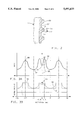
- FIG. 3 illustrates flux densities calculated via finite element analysis for an air gap between the magnetoresistive sensor 17 and the screw 14, including a small groove 54 within land 50 measuring 1 mm. deep by 2 mm. wide.
- the contour 61 illustrates the approximation of the screw 14 used for the model.
- the pattern of the flux density 60 in FIGS. 3a and 3b follows the surface pattern 61 of the approximated screw surface.
- High points 66 represent flux densities at lands
- low points 64 represent flux densities in the large grooves
- reference 70 represents the flux density at position 68, corresponding to the small groove 54.
- Reference 62 illustrates the mean flux density.
- the flux density drop across the small groove is significant, from 0.3 T down to 0.2 T, despite the small size of the groove.
- the plotted flux density is based on a magnetoresistive sensor comprising a hot pressed iron-neodymium-boron alloy permanent magnet of a known type (e.g., MQ2TM), 3 mm. thick and 6 mm. wide.
- one small groove at any position along the screw.
- the reference position would only be identified each time this groove passes the sensor, which may not happen for some time after start-up of the vehicle.
- placement of too many sensors and small grooves may become impractical from a cost standpoint.
- one small groove is sensed when the vehicle is in the static equilibrium position of the vehicle with an assumed average sized driver with no payload and the other small groove is sensed at the static equilibrium position of the vehicle fully loaded.
- This combination offers an appropriate compromise between obtaining absolute position information rapidly after power-up, on the one hand, and sensor proliferation, on the other hand.
- These two positions could be, for example, two inches apart and are denoted as the "zero position" and "two-inch position,” respectively.
- the two magnet sensor assemblies are connected according to this invention in a bridge configuration located at some angular distance 76 from one another, as shown in FIG. 4.
- FIG. 4 illustrates a portion of screw 14 and small grooves 54 and 55 in the helical land 50 of the screw.
- the grooves 54 and 55 are, in this example, axially two inches apart, placed in the lands 50 so that, at static equilibrium position for the vehicle with only a driver and no payload, groove 55 is nominally at sensor position 72.
- groove 54 is at sensor position 74, where the second sensor is located.
- the small grooves 54 and 55 are located at an angular distance 76 azimuthally.
- the sensors are mounted at the sensor positions 72 and 74, which may be chosen as follows.
- the azimuthal angle between the sensor positions is the same as the azimuthal angle between the grooves 54 and 55.
- the sensors are located along an imaginary helix having the same helix angle 77 as the helical lands 50 of the screw 14.
- the helix angle 77 is defined as the angle of the helix of the screw land 50 with respect to an imaginary plane perpendicular to the screw axis 61.
- the sensors may either be co-linear along the imaginary helix or may be spaced axially apart in increments equal to the pitch or distance between the centers of consecutive lands of the screw.
- the axial distance between the sensors is nX mm. where n is an integer including 0, 1, 2, 3, etc..
- the two sensors By placing the sensors either co-linearly along the helix or at multiples of the pitch distance apart helically, the two sensors have identical outputs as the screw moves past the sensors until groove 54 passes sensor position 74 or until groove 55 passes sensor position 72. Because, in this example, the screw 14 does not rotate about its axis, there is no chance of groove 54 triggering the sensor at position 72 nor of groove 55 triggering the sensor at position 74.
- the sensor assembly 18 includes sensors 16 and 17 comprising magnets 57 and 56 respectively and magnetoresistive elements 59 and 58, respectively, as shown. Leads 80 are provided to connect the sensor assembly to a control unit. When mounted facing the screw 14, sensor assembly 18 places the sensors 16 and 17 at their sensor positions 72 and 74 respectively.
- magnetoresistive elements 59' and 58' mounted thereon.
- This method simplifies assembly, allows the use of a common lead frame to support the magnet, leads and the two magnetoresistors and reduces the number of leads to a total of three.
- the total volume of the magnet is larger than the total volume of magnets 56 and 57 shown in FIG. 5.
- reference 88 represents the output signal of sensor 16
- reference 89 represents the output signal of sensor 17
- reference 90 represents the output signal of a bridge circuit (described in more detail below) including the two sensors 16 and 17.
- trace 88 dips. While the screw 14 is at displacement position x2, trace 89 dips. Otherwise, the outputs of the two sensors 16 and 17 are identical, as shown.
- the output trace 90 of the bridge circuit appears as shown.
- sensor 55 is triggered and the output of the bridge circuit goes high, as shown.
- sensor 56 is triggered and the output of the bridge circuit goes low, as shown.
- the bridge circuit can be used to provide two absolute position output signals.
- the output of the bridge and trigger circuit would then be as follows, when the actuator extends to a first predetermined position, the bridge circuit goes high and a first absolute position signals is provided. When the actuator extends to a second predetermined position, the bridge circuit goes low and a second absolute position signal is provided. When the actuator is extended to positions other than the first and second predetermined positions, the bridge circuit remains at its neutral value and no absolute position signal is provided.
- a bridge and trigger circuit 151 for use with sensors 16 and 17 is shown in the schematic diagram for a control system for implementation of this invention.
- the sensors 16 and 17 are connected in series between the vehicle supply voltage and ground.
- Line 153, coupled to the junction of sensors 16 and 17, is provided to the inverting input of amplifier 156 and the non-inverting input of amplifier 154.
- the other inputs of amplifiers 154 and 156 are biased by resistors 150, 152 and 159, coupled in series between the vehicle supply voltage and ground, as shown.
- the purpose of resistor 159 is to set a non-zero threshold, delta-v, as shown in FIG. 7.
- resistors 150, 152 and 159 control the trigger levels of amplifiers 154 and 156 so that when the value of line 153 goes high, above a first threshold, an output signal appears on line 155 indicating that the first reference position is sensed.
- line 153 falls below a second threshold, an output signal is triggered on line 157, indicating that the second reference position is sensed.
- an output signal appears on line 155.
- an output signal appears on line 157.
- no output signal appears on lines 155 or 157.
- control unit 158 of a known type that typically includes a microprocessor 160 and RAM and ROM.
- Sensors 140, 142, 144 and 146 each correspond to one of the discs in the rotary encoder 30 so that sensors 140, 142 and 144 provide commutation control pulses and so that the sensor 146 provides high resolution pulses from the high resolution encoder disc.
- the actuator is to be used only as a generator and not as a motor, i.e., in a semi-active suspension control implementation, then only sensor 146 is needed as the commutation control pulses by sensors 140, 142 and 144 are not necessary.
- the commutation control pulses provided by sensors 140, 142 and 144 are necessary in as long as the motor/alternator 24 is a brushless DC motor.
- the control unit receives the signals from bus 148 and from lines 155 and 157 and determines a relative displacement between the vehicle wheel and body as follows.
- a signal on line 155 indicates absolutely that the relative displacement between the body and wheel corresponds to the actuator being extended to the zero position.
- control unit 158 updates the relative displacement signal so that the relative displacement signal corresponds to the zero position, if it does not already correspond to the zero position.
- a signal on line 157 indicates absolutely that the relative displacement between the body and wheel corresponds to the actuator being extended to the two inch position.
- control unit 158 updates the relative displacement signal so that the relative displacement signal corresponds to the two inch position, if it does not already correspond to the two inch position.
- the control unit 158 counts pulses received from sensor 146 and adds or subtracts a proper increment to the position signal maintained in memory in control unit 158.
- the relative displacement may be determined with the customized circuitry dedicated to monitoring the signals on lines 155, 157 and bus 148 to determine a relative displacement signal.
- lines 155, 157 and bus 158 may be provided directly to microprocessor 160, which may be programmed to count the relative movement pulses from sensor 146, updating the relative displacement signal in response thereto, and resetting the relative displacement signal to the appropriate values each time an absolute position on lines 155 or 157 is provided.
- microprocessor 160 may be programmed to count the relative movement pulses from sensor 146, updating the relative displacement signal in response thereto, and resetting the relative displacement signal to the appropriate values each time an absolute position on lines 155 or 157 is provided.
- control for the suspension system can be implemented in the manner described in the above-described patent and co-pending applications or in any other suitable manner known to those skilled in the art.
- the control unit determines appropriate control commands and applies those control commands to the variable load 162, which applies a load across coils 164, 166, 168 when the actuator is used as a variable damper to control the damping force of the actuator.
- An example variable load is described in U.S. Pat. No. 4,815,575, assigned to assignee of this invention and having a disclosure incorporated herein by reference.
- the motor/alternator 24 includes a rotary encoder 112 for use with Hall effect/magnetoresistive sensors 114 to detect relative rotational movement of motor/alternator 24.
- Support 118 supporting sensor head 120 is mounted to the housing 111 of motor/alternator 24.
- Sensor head 120 includes sensors 122 (only one shown) of similar type and positioning as the sensors described above with reference to FIGS. 4, 5 and 6.
- the outer housing 125 of the ball nut 124 includes two grooves 130 and 132 (see also FIG. 10) having relative axial and radial distances apart similar to the grooves 54 and 55 illustrated in FIG. 4 (since the ball nut does not include a helical structure the limitations relating to the helix need not apply).
- FIG. 10 illustrates the grooves 130 and 132 and the outer housing 125 of ball nut 124.
- the absolute positions sensors can be implemented to provide absolute position signals anywhere along the range of linear travel of the linearly translating portion of the actuator. This provides an advantage over systems that must bottom or top out to obtain an absolute position reference.
- any number or location of the absolute position sensors may be used, as a system designer desires.
Abstract
An apparatus comprising a rotating element, a rotary to linear converter, a linearly moving element that linearly extends and retracts when the rotating element rotates in first and second directions, a rotary sensor assembly, integrally constructed with the rotating element, for determining relative movement of the rotating element and for thereby determining relative movement of the linearly moving element, a linear sensor assembly, integrally constructed with the linearly moving element, for providing an absolute position signal each time that the linearly moving element extends or retracts to a predetermined position.
Description
This is a continuation of application Ser. No. 08/115,610 filed on Sep. 3, 1993 now abandoned, which is a continuation-in-part of U.S. patent applications, Ser. Nos. 07/702,873 now U.S. Pat. No. 5,276,621, and 07/702,874, 07/702,875 both pending, all filed May 20, 1991 and assigned to the assignee of this invention and all having disclosures incorporated herein by reference. The subject of this application is related to the subject of copending application, U.S. Ser. No. 08/115,604, filed concurrently with this application, assigned to the assignee of this invention and the disclosure of which is incorporated herein by reference.
In controlling active and semi-active automotive suspension systems, a position sensor is typically required to provide the controller with information regarding the position of the wheel with respect to the car body, which usually has a displacement range of several inches. The velocity of the relative displacement between the car body and the wheel is also typically required by the suspension controller, but can be obtained by differentiation of the position signal, or, preferably, by using an estimator.
Currently available position sensors include (a) LVDT's, which are an expensive option for mass production applications, (b) resistive potentiometers, which are subject to wear because of their sliding contact surfaces and (c) optical sensors, which are subject to contamination, are temperature limited and are relatively expensive. Magnetoresistive technology may be used to sense linear position but typically its application is avoided due to the requirement of temperature compensation.
Advantageously, this invention provides a method and apparatus for sensing position of electromechanical automotive suspension system. This invention provides a sensor method and apparatus for use with actuators comprising a brushless motor or rotary alternator engaged with a rotary-to-linear converter, which consists of either a rotating nut and translating screw or a rotating screw and translating nut. Advantageously, the sensor according to this invention comprises an integral part of the suspension mechanism, facilitating assembly, reducing the number of external wires and providing a low cost high reliability option.
Advantageously, according to this invention, the brushless motor includes a rotary encoder to provide an indication of motor rotation and therefore of linear travel. Since the rotary encoder cannot provide absolute position information because it cannot distinguish one motor revolution from another, it is limited to measuring relative displacement with respect to an initial point, which is subject to drift over time. Therefore, according to this invention, a sensor assembly providing at least one reference position is mounted across an air gap from the linearly translating portion of the suspension. The sensor assembly, the rotary encoder and the suspension actuator comprise an integral unit that provides a controllable variable damper/actuator, including a rotor position sensor for providing a relative movement signal and an absolute position sensor for providing an absolute position signal each time that the actuator is extended to a predetermined position. Thus, the rotary encoder provides relative movement signals that may be counted to update the relative displacement of the actuator, and the absolute position sensor provides a signal, that allows periodic correction of the relative displacement to correct for possible drift.
In a preferred implementation, the sensor assembly includes two separate sensors mounted across an air-gap from the linearly translating portion of the suspension. The two sensors are electronically configured into a bridge circuit. Two specific locations of the translating members each include a small groove for triggering one of the sensors. One groove triggers one sensor each time that the actuator extends to a first reference position and the second groove triggers the second sensor each time that the actuator extends to a second reference position. The sensor system according to this invention is integrated into the electromechanical actuator itself, thus eliminating the need for externally mounted sensors. Thus, the sensor system for the suspension unit includes both a rotary sensor for sensing relative displacement and first and second absolute position sensors for sensing first and second absolute positions of the suspension system.
A more detailed description of this invention, along with various embodiments thereof, is set forth below.
FIG. 1 illustrates an electromechanical suspension actuator implementing the sensor system according to this invention.
FIG. 2 is an illustration of the actuator screw according to this invention.
FIGS. 3a and 3b illustrate the operation of the absolute position sensor according to this invention.
FIG. 4 illustrates an example sensor and groove configuration according to this invention.
FIG. 5 illustrates an example sensor according to this invention.
FIG. 6 illustrates a second example sensor according to this invention.
FIGS. 7a, 7b and 7c illustrate sensor and bridge circuit outputs according to this invention.
FIG. 8 illustrates this invention schematically, including a sensor bridge circuit.
FIGS. 9 and 10 illustrate a second example actuator according to this invention.
In the description below, the following nomenclature is used: A vehicle quarter car suspension has a "relative displacement," which is representative of the distance between the sprung mass (vehicle body) and the unsprung mass (wheel). Each relative displacement position of the quarter car suspension corresponds to a position of extension (or retraction) of the variable force actuator. "Relative movement" of the actuator is determined based on counting pulses, ideally beginning with a known relative position of the actuator, and allows for tracking of the relative displacement based on counting of the relative movement signals. An "absolute position" of the actuator is determined by an absolute position signal and provides relative displacement information based on an absolute position signal.
Referring to FIG. 1, the electromechanical actuator according to this invention includes wheel mount 12 attached to linearly translating screw 14, which is coupled through a ball nut transmission 22 to electric motor/alternator 24. The interaction of the ball nut 22 and screw 14 translates up and down movement of the actuator caused by forces applied to wheel mount 12 and chassis mount 34 into rotational movement of the motor/alternator 24. Thus, when the chassis mount 34 is mounted to the vehicle body and the wheel mount 12 is mounted to the vehicle wheel, normal suspension system movement causes the actuator to extend and retract in a linear movement (note, in the active suspension implementation, power supplied to the actuator may cause movement of the suspension). The linear movements are translated by the screw and ball nut into rotary movements of motor/alternator 24.
In the case where motor/alternator 24 is a brushless DC motor, encoder 30 may also include in one single assembly several tracks designed to control the motor drive switching circuit. For instance, encoder 30 may be the type described in Research Disclosure 33824, published June, 1992, having a disclosure incorporated herein by reference. Preferably the rotary encoder 30 is then a four-track encoder wheel that provides commutation pulses and high resolution rotary position signals. The encoder may comprise four co-planar encoder discs, three commutation encoder discs and one high resolution encoder disc, all of them properly spaced and oriented with respect to each other and over-molded to form a solid rigid assembly that is attached to the motor shaft. In some applications, particularly if very high resolution is required, more than one high resolution encoder disk may be included in encoder 30.
The encoder of this type is intended for operation with a single package stationary sensor comprising four magnetic field sensitive devices, e.g., Hall effect sensors or magnetoresistors, spaced to match the spacing of the four co-planar encoder discs. The discs are made from a soft magnetic material, such as low carbon steel, using a precision blanking process and have a balanced peripheral shape to provide proper position information to the Hall effect sensors. In response to the output signals from the sensors, an inverter circuit is easily controlled in a known manner of controlling brushless DC motors to control output force of the actuator in accordance with commands developed by the controller.
Referring now to FIGS. 2 and 4, a portion of the screw 14 is shown, comprising a spiral combination of lands 50 and bearing grooves 52, which together track a set of bearings (not shown) in the ball nut 22 in a known manner. In two positions along the screw 14, small grooves 54 and 55 are made by removing a small amount of material in the screw land 50. Each of the small grooves may be detected by a magnetoresistive sensor 16, 17 including a magnet 56 and magnetoresistor 58, as shown, or by a Hall effect sensor. The magnetoresistive sensors 16, 17 are stationarily mounted facing the screw 14, as shown, to sense the vertical movement of the screw 14 and the passing of lands 50, bearing grooves 52, and the small grooves 54, 55 with vertical movement on the screw 14.
A magnetoresistive sensor such as the sensor 17 shown, provides a low output when a bearing groove 52 passes the sensor 17 and a high output when a land 50 passes the sensor 17. The small groove 54 is also detected by the sensor 17 to bring the sensor output lower. Because the flux density from the magnet decreases rapidly with air gap depth, the small groove 54 (or 55) in the land 50 need not be very deep to provide a significant drop in signal strength. For this reason, the groove can be made deep and large enough to be useful for sensing purposes, yet small enough to be insignificant for the proper operation of the screw mechanism and insignificant to the structural integrity of the screw.
FIG. 3 illustrates flux densities calculated via finite element analysis for an air gap between the magnetoresistive sensor 17 and the screw 14, including a small groove 54 within land 50 measuring 1 mm. deep by 2 mm. wide. The contour 61 illustrates the approximation of the screw 14 used for the model.
As can be seen, the pattern of the flux density 60 in FIGS. 3a and 3b follows the surface pattern 61 of the approximated screw surface. High points 66 represent flux densities at lands, low points 64 represent flux densities in the large grooves and reference 70 represents the flux density at position 68, corresponding to the small groove 54. Reference 62 illustrates the mean flux density. The flux density drop across the small groove is significant, from 0.3 T down to 0.2 T, despite the small size of the groove. The plotted flux density is based on a magnetoresistive sensor comprising a hot pressed iron-neodymium-boron alloy permanent magnet of a known type (e.g., MQ2™), 3 mm. thick and 6 mm. wide.
In implementing this invention, it is possible to use one small groove at any position along the screw. However, the reference position would only be identified each time this groove passes the sensor, which may not happen for some time after start-up of the vehicle. On the other hand, placement of too many sensors and small grooves may become impractical from a cost standpoint. According to this invention, it is preferred that two sensors and two small grooves be used. In an example configuration, one small groove is sensed when the vehicle is in the static equilibrium position of the vehicle with an assumed average sized driver with no payload and the other small groove is sensed at the static equilibrium position of the vehicle fully loaded. This combination offers an appropriate compromise between obtaining absolute position information rapidly after power-up, on the one hand, and sensor proliferation, on the other hand. These two positions could be, for example, two inches apart and are denoted as the "zero position" and "two-inch position," respectively.
To eliminate difficulty in using each sensor singly and trying to distinguish between the large screw grooves and the small grooves in the lands, the two magnet sensor assemblies are connected according to this invention in a bridge configuration located at some angular distance 76 from one another, as shown in FIG. 4.
FIG. 4 illustrates a portion of screw 14 and small grooves 54 and 55 in the helical land 50 of the screw. The grooves 54 and 55 are, in this example, axially two inches apart, placed in the lands 50 so that, at static equilibrium position for the vehicle with only a driver and no payload, groove 55 is nominally at sensor position 72. At the static equilibrium position for the vehicle fully loaded, groove 54 is at sensor position 74, where the second sensor is located.
The small grooves 54 and 55 are located at an angular distance 76 azimuthally. The sensors are mounted at the sensor positions 72 and 74, which may be chosen as follows. The azimuthal angle between the sensor positions is the same as the azimuthal angle between the grooves 54 and 55. The sensors are located along an imaginary helix having the same helix angle 77 as the helical lands 50 of the screw 14. The helix angle 77 is defined as the angle of the helix of the screw land 50 with respect to an imaginary plane perpendicular to the screw axis 61. The sensors may either be co-linear along the imaginary helix or may be spaced axially apart in increments equal to the pitch or distance between the centers of consecutive lands of the screw. Thus, with a distance from center to center between consecutive lands of screw 14 equal to X mm., the axial distance between the sensors is nX mm. where n is an integer including 0, 1, 2, 3, etc..
By placing the sensors either co-linearly along the helix or at multiples of the pitch distance apart helically, the two sensors have identical outputs as the screw moves past the sensors until groove 54 passes sensor position 74 or until groove 55 passes sensor position 72. Because, in this example, the screw 14 does not rotate about its axis, there is no chance of groove 54 triggering the sensor at position 72 nor of groove 55 triggering the sensor at position 74.
Referring now to FIG. 5, a face view is shown of the portion of the sensor assembly 18 that faces the screw 14. The sensor assembly 18 includes sensors 16 and 17 comprising magnets 57 and 56 respectively and magnetoresistive elements 59 and 58, respectively, as shown. Leads 80 are provided to connect the sensor assembly to a control unit. When mounted facing the screw 14, sensor assembly 18 places the sensors 16 and 17 at their sensor positions 72 and 74 respectively.
Referring to FIG. 6, advantageously, only one magnet 256 may be used with magnetoresistive elements 59' and 58' mounted thereon. This method simplifies assembly, allows the use of a common lead frame to support the magnet, leads and the two magnetoresistors and reduces the number of leads to a total of three. However, the total volume of the magnet is larger than the total volume of magnets 56 and 57 shown in FIG. 5.
Referring to FIGS. 7a, 7b and 7c, reference 88 represents the output signal of sensor 16, reference 89 represents the output signal of sensor 17 and reference 90 represents the output signal of a bridge circuit (described in more detail below) including the two sensors 16 and 17. As shown, when the screw 14 is at displacement position x1 (the zero position), trace 88 dips. While the screw 14 is at displacement position x2, trace 89 dips. Otherwise, the outputs of the two sensors 16 and 17 are identical, as shown.
With the two sensors 16 and 17 connected in a bridge configuration, the output trace 90 of the bridge circuit appears as shown. When the screw reaches the zero position, sensor 55 is triggered and the output of the bridge circuit goes high, as shown. When the screw 14 reaches the two inch position, sensor 56 is triggered and the output of the bridge circuit goes low, as shown. By connecting the bridge circuit to a trigger having high and low thresholds 92 and 94, the bridge circuit can be used to provide two absolute position output signals. The output of the bridge and trigger circuit would then be as follows, when the actuator extends to a first predetermined position, the bridge circuit goes high and a first absolute position signals is provided. When the actuator extends to a second predetermined position, the bridge circuit goes low and a second absolute position signal is provided. When the actuator is extended to positions other than the first and second predetermined positions, the bridge circuit remains at its neutral value and no absolute position signal is provided.
Referring now to FIG. 8, a bridge and trigger circuit 151 for use with sensors 16 and 17 is shown in the schematic diagram for a control system for implementation of this invention. The sensors 16 and 17 are connected in series between the vehicle supply voltage and ground. Line 153, coupled to the junction of sensors 16 and 17, is provided to the inverting input of amplifier 156 and the non-inverting input of amplifier 154. The other inputs of amplifiers 154 and 156 are biased by resistors 150, 152 and 159, coupled in series between the vehicle supply voltage and ground, as shown. The purpose of resistor 159 is to set a non-zero threshold, delta-v, as shown in FIG. 7.
The value of resistors 150, 152 and 159 control the trigger levels of amplifiers 154 and 156 so that when the value of line 153 goes high, above a first threshold, an output signal appears on line 155 indicating that the first reference position is sensed. When line 153 falls below a second threshold, an output signal is triggered on line 157, indicating that the second reference position is sensed. Thus, each time that screw 14 is extended to the first reference position, an output signal appears on line 155. Each time that screw 14 is extended to the second reference position, an output signal appears on line 157. When the screw is not at either the first or second reference positions, no output signal appears on lines 155 or 157.
The signals on lines 155 and 157, along with the signals on bus 148 from sensors 140, 142, 144 and 146 proximate to encoder 30 are provided to control unit 158 of a known type that typically includes a microprocessor 160 and RAM and ROM. Sensors 140, 142, 144 and 146 each correspond to one of the discs in the rotary encoder 30 so that sensors 140, 142 and 144 provide commutation control pulses and so that the sensor 146 provides high resolution pulses from the high resolution encoder disc.
In the event that the actuator is to be used only as a generator and not as a motor, i.e., in a semi-active suspension control implementation, then only sensor 146 is needed as the commutation control pulses by sensors 140, 142 and 144 are not necessary. In the active suspension system case where the actuator is controlled as both a generator and a motor, then the commutation control pulses provided by sensors 140, 142 and 144 are necessary in as long as the motor/alternator 24 is a brushless DC motor.
The control unit receives the signals from bus 148 and from lines 155 and 157 and determines a relative displacement between the vehicle wheel and body as follows. A signal on line 155 indicates absolutely that the relative displacement between the body and wheel corresponds to the actuator being extended to the zero position. Thus control unit 158 updates the relative displacement signal so that the relative displacement signal corresponds to the zero position, if it does not already correspond to the zero position. A signal on line 157 indicates absolutely that the relative displacement between the body and wheel corresponds to the actuator being extended to the two inch position. Thus control unit 158 updates the relative displacement signal so that the relative displacement signal corresponds to the two inch position, if it does not already correspond to the two inch position. When the control unit 158 is not receiving signals on lines 155 or 157, the control unit 158 counts pulses received from sensor 146 and adds or subtracts a proper increment to the position signal maintained in memory in control unit 158.
Each time that screw 14 extends or retracts to the first predetermined position (i.e., the zero position), a pulse appears on line 155. Each time that screw 14 extends or retracts to the second predetermined position (i.e., the two inch position), a pulse appears on line 157. When the actuator screw is not extended or retracted to one of the predetermined positions, no absolute position signals are provided. Thus, with each pulse on lines 155 or 157, the position signal is reset to either the zero reference position or the two inch reference position and when pulses are not received on lines 155 or 157, the control unit 158 counts up or counts down with proper increments responsive to signals received from sensor 146.
Using the above information, one skilled in the art can easily determine relative displacement between the body and wheel using the actuator of this invention. The relative displacement may be determined with the customized circuitry dedicated to monitoring the signals on lines 155, 157 and bus 148 to determine a relative displacement signal. Alternatively, lines 155, 157 and bus 158 may be provided directly to microprocessor 160, which may be programmed to count the relative movement pulses from sensor 146, updating the relative displacement signal in response thereto, and resetting the relative displacement signal to the appropriate values each time an absolute position on lines 155 or 157 is provided. Those skilled in the art can implement either method and further detail need not be set forth herein.
Once the relative displacement signal is determined as described above, the control for the suspension system can be implemented in the manner described in the above-described patent and co-pending applications or in any other suitable manner known to those skilled in the art. The control unit determines appropriate control commands and applies those control commands to the variable load 162, which applies a load across coils 164, 166, 168 when the actuator is used as a variable damper to control the damping force of the actuator. An example variable load is described in U.S. Pat. No. 4,815,575, assigned to assignee of this invention and having a disclosure incorporated herein by reference.
Implementation of this invention into known control schemes allows elimination of the prior used position sensing device, such as the LVDT.
Referring now to FIG. 9, a second example actuator with position sensing according to this invention is shown. The actuator includes a wheel mount 128 coupled through a tubular support 126 to ball nut 124. The wheel mount 128 is mounted to the vehicle wheel and the chassis mount 116 is mounted to the vehicle chassis. The ball nut 124, tubular support 126 and wheel support 128 extend and retract linearly with respect to motor/alternator 24 in response to normal suspension system movements. The linear extension and retraction of the actuator translate into rotational motion of the screw 104 coupled to motor/alternator 24, which is mounted within bearings 108 and 110 in the housing 111 shown.
The motor/alternator 24 includes a rotary encoder 112 for use with Hall effect/magnetoresistive sensors 114 to detect relative rotational movement of motor/alternator 24. Support 118 supporting sensor head 120 is mounted to the housing 111 of motor/alternator 24. Sensor head 120 includes sensors 122 (only one shown) of similar type and positioning as the sensors described above with reference to FIGS. 4, 5 and 6.
The outer housing 125 of the ball nut 124 includes two grooves 130 and 132 (see also FIG. 10) having relative axial and radial distances apart similar to the grooves 54 and 55 illustrated in FIG. 4 (since the ball nut does not include a helical structure the limitations relating to the helix need not apply). Interaction of the grooves 127 and sensors 122, which are connected in a bridge circuit as described above, provides two absolute position reference signals for the actuator shown.
FIG. 10 illustrates the grooves 130 and 132 and the outer housing 125 of ball nut 124.
Advantageously, according to this invention, the absolute positions sensors can be implemented to provide absolute position signals anywhere along the range of linear travel of the linearly translating portion of the actuator. This provides an advantage over systems that must bottom or top out to obtain an absolute position reference.
In implementing this invention, any number or location of the absolute position sensors may be used, as a system designer desires.
The above-described implementations of this invention are example implementations. Various other improvements, modifications to this invention may occur to those skilled in the art and such improvements and modifications will fall within the scope of this invention as set forth below.
Claims (5)
1. An apparatus comprising:
a rotating element;
a linearly moving element;
a rotary to linear converter coupled to the rotating element and the linearly moving element, wherein the rotary to linear converter translates linear movement of the linearly moving element to rotary movement of the rotating element;
means for determining relative movement of the rotating element;
first and second grooves in the linearly moving element, the first and second grooves separated azimuthally by a predetermined angle greater than zero and vertically by a predetermined distance;
first and second sensors separated azimuthally by the predetermined angle wherein the first sensor responds to proximity of the first groove and the second sensor responds to proximity of the second groove, wherein the first and second sensors are coupled in a bridge comprising means for providing an output signal having (a) a first state when neither the first nor the second groove is proximate to either the first or the second sensor, (b) a second state when the first groove is proximate to the first sensor, and (c) a third state when the second groove is proximate to the second sensor.
2. The apparatus set forth in claim 1 wherein
the linearly moving element comprises a screw having a helical land at a fixed land angle;
the first and second grooves are located in the helical land; and
the first and second sensors are located co-linearly along a helical spiral facing the helical land.
3. The apparatus set forth in claim 1 wherein the linearly moving element comprises a screw having a helical land and wherein the first and second sensors have an axial distance apart equal to a whole integer multiple of a distance between consecutive centers of lands of the screw.
4. A suspension system actuator comprising:
a linearly translating element;
a rotary to linear converter mechanically connected to the linearly translating element;
a rotating element mechanically connected to the rotary to linear convertor so that extension and retraction of the linearly translating element translates to rotation of the rotating element, wherein the rotating element includes a brushless motor/alternator including a rotary encoder and a corresponding sensor device providing an indication of relative motor rotation and therefore of linear travel of the linearly translating element, wherein the indication of relative motor rotation is subject to driftover time;
a sensor assembly providing at least one reference signal indicative of a predetermined linear position of the linearly translating element, the sensor assembly mounted across an air gap from the linearly translating element, wherein the sensor assembly, rotary encoder, motor/alternator, and linearly translating element comprise an integral unit that provides a controllable variable force, continuous relative movement signals, and at least one absolute position signal when the linearly translating element reaches the predetermined position, wherein the absolute position signal is used to correct for drift of the relative movement signal.
5. The suspension system actuator set forth in claim 4, wherein the sensor assembly includes two separate sensors, mounted across an air-gap from the linearly translating element, the two sensors coupled to form a bridge circuit, wherein two locations of the translating members each include a small groove for triggering one of the sensors, one groove triggers one sensor at a first reference position and the other groove triggering the second sensor at a second reference position.
Priority Applications (1)
| Application Number | Priority Date | Filing Date | Title |
|---|---|---|---|
| US08/390,916 US5491633A (en) | 1991-05-20 | 1995-02-17 | Position sensor for electromechanical suspension |
Applications Claiming Priority (5)
| Application Number | Priority Date | Filing Date | Title |
|---|---|---|---|
| US07/702,874 US5475596A (en) | 1991-05-20 | 1991-05-20 | Full car semi-active suspension control based on quarter car control |
| US07/702,873 US5276621A (en) | 1991-05-20 | 1991-05-20 | Quarter car variable force suspension system control |
| US07/702,875 US5434782A (en) | 1991-05-20 | 1991-05-20 | Suspension system state observer |
| US11561093A | 1993-09-03 | 1993-09-03 | |
| US08/390,916 US5491633A (en) | 1991-05-20 | 1995-02-17 | Position sensor for electromechanical suspension |
Related Parent Applications (1)
| Application Number | Title | Priority Date | Filing Date |
|---|---|---|---|
| US11561093A Continuation | 1991-05-20 | 1993-09-03 |
Publications (1)
| Publication Number | Publication Date |
|---|---|
| US5491633A true US5491633A (en) | 1996-02-13 |
Family
ID=27494025
Family Applications (1)
| Application Number | Title | Priority Date | Filing Date |
|---|---|---|---|
| US08/390,916 Expired - Fee Related US5491633A (en) | 1991-05-20 | 1995-02-17 | Position sensor for electromechanical suspension |
Country Status (1)
| Country | Link |
|---|---|
| US (1) | US5491633A (en) |
Cited By (76)
| Publication number | Priority date | Publication date | Assignee | Title |
|---|---|---|---|---|
| US5725358A (en) * | 1995-08-30 | 1998-03-10 | Binks Manufacturing Company | Pressure regulated electric pump |
| US5963028A (en) * | 1997-08-19 | 1999-10-05 | Allegro Microsystems, Inc. | Package for a magnetic field sensing device |
| US6249300B1 (en) | 1999-07-15 | 2001-06-19 | Eastman Kodak Company | Method and apparatus for positioning a writing assembly of an image processing apparatus |
| US6404184B1 (en) * | 2000-08-07 | 2002-06-11 | Sohail Tabrizi | Simplified low backlash LVDT coupling |
| EP1219476A1 (en) * | 2000-12-29 | 2002-07-03 | Mando Corporation | Motor controlled suspension system for adjusting the height of a vehicle body and a damping force |
| KR20020067440A (en) * | 2002-04-17 | 2002-08-22 | 강성덕 | power free ball screw magnetorheological damper |
| US6450048B1 (en) * | 2000-02-11 | 2002-09-17 | Gomaco Corp | Hydraulic cylinder monitoring apparatus |
| US20030001346A1 (en) * | 1998-11-11 | 2003-01-02 | Hamilton James M. | Enhanced computer optimized adaptive suspension system and method |
| US6515471B1 (en) | 2000-10-11 | 2003-02-04 | The Torrington Company | Absolute position hall string sensor |
| US20030117037A1 (en) * | 2000-05-19 | 2003-06-26 | Jean-Francois Pfister | Linear or rotary actuator |
| US6595041B2 (en) * | 2000-06-28 | 2003-07-22 | Brian Nils Hansen | Method and apparatus for magnetic levitation |
| EP1464520A1 (en) * | 2003-04-01 | 2004-10-06 | Siemens SGP Verkehrstechnik GmbH | Levelling and inclination control of a railway body, with a gear transmission driven by an electric motor. |
| US20050173994A1 (en) * | 2004-02-09 | 2005-08-11 | Societe Industrielle De Sonceboz Sa | Linear actuator |
| US20050211516A1 (en) * | 2002-06-06 | 2005-09-29 | Takuhiro Kondo | Electromagnetic damper |
| US20050230201A1 (en) * | 2004-04-16 | 2005-10-20 | Takuhiro Kondou | Electromagnetic shock absorber for vehicle |
| US20060055398A1 (en) * | 2004-09-14 | 2006-03-16 | Denso Corporation | Rotation sensor |
| US20060113734A1 (en) * | 2004-12-01 | 2006-06-01 | Hyundai Mobis Co., Ltd. | Active roll control system using a motor |
| US20060163863A1 (en) * | 2002-11-28 | 2006-07-27 | Siegfried Ellmann | Vehicle chassis |
| US20070160438A1 (en) * | 2006-01-12 | 2007-07-12 | Larry Cope | Power transmission with bead drive |
| EP1958800A3 (en) * | 2007-02-14 | 2009-12-02 | Audi Ag | Electromechanical control device for the wheel suspension in motor vehicles |
| US20090317027A1 (en) * | 2008-06-24 | 2009-12-24 | Hr Textron, Inc. | Position sensing assembly |
| US20100007103A1 (en) * | 2008-07-10 | 2010-01-14 | Hyundai Motor Company | Actuator for Active Roll Control System |
| EP2145781A1 (en) | 2008-07-19 | 2010-01-20 | Audi Ag | Motor vehicle with active suspension |
| US20100059944A1 (en) * | 2008-09-08 | 2010-03-11 | Oteman David G | Counter-Rotating Motors with Linear Output |
| US20100141249A1 (en) * | 2008-12-05 | 2010-06-10 | Virgil Ararao | Magnetic Field Sensors and Methods for Fabricating the Magnetic Field Sensors |
| US20100188078A1 (en) * | 2009-01-28 | 2010-07-29 | Andrea Foletto | Magnetic sensor with concentrator for increased sensing range |
| US20100330708A1 (en) * | 2007-03-29 | 2010-12-30 | Allegro Microsystems, Inc. | Methods for multi-stage molding of integrated circuit package |
| US20120049480A1 (en) * | 2010-08-31 | 2012-03-01 | Hyundai Motor Company | Active Roll Control System for Vehicle |
| US8266743B2 (en) | 2010-08-23 | 2012-09-18 | Midmark Corporation | Examination table with motion tracking |
| US20130327168A1 (en) * | 2012-06-08 | 2013-12-12 | Timotion Technology Co., Ltd. | Gear motor having safety mechanism |
| US8629539B2 (en) | 2012-01-16 | 2014-01-14 | Allegro Microsystems, Llc | Methods and apparatus for magnetic sensor having non-conductive die paddle |
| US8844943B2 (en) * | 2012-12-17 | 2014-09-30 | Hyundai Motor Company | Electronic control suspension system for vehicles |
| US9411025B2 (en) | 2013-04-26 | 2016-08-09 | Allegro Microsystems, Llc | Integrated circuit package having a split lead frame and a magnet |
| US9494660B2 (en) | 2012-03-20 | 2016-11-15 | Allegro Microsystems, Llc | Integrated circuit package having a split lead frame |
| EP2645561A3 (en) * | 2012-03-27 | 2016-11-23 | Hamilton Sundstrand Corporation | Extended range absolute position sensing |
| US9666788B2 (en) | 2012-03-20 | 2017-05-30 | Allegro Microsystems, Llc | Integrated circuit package having a split lead frame |
| CN106969285A (en) * | 2015-10-19 | 2017-07-21 | 百奇股份有限公司 | Illuminating equipment and corresponding control methods |
| US9719806B2 (en) | 2014-10-31 | 2017-08-01 | Allegro Microsystems, Llc | Magnetic field sensor for sensing a movement of a ferromagnetic target object |
| US9720054B2 (en) | 2014-10-31 | 2017-08-01 | Allegro Microsystems, Llc | Magnetic field sensor and electronic circuit that pass amplifier current through a magnetoresistance element |
| US9810519B2 (en) | 2013-07-19 | 2017-11-07 | Allegro Microsystems, Llc | Arrangements for magnetic field sensors that act as tooth detectors |
| US9812588B2 (en) | 2012-03-20 | 2017-11-07 | Allegro Microsystems, Llc | Magnetic field sensor integrated circuit with integral ferromagnetic material |
| US9817078B2 (en) | 2012-05-10 | 2017-11-14 | Allegro Microsystems Llc | Methods and apparatus for magnetic sensor having integrated coil |
| US9823092B2 (en) | 2014-10-31 | 2017-11-21 | Allegro Microsystems, Llc | Magnetic field sensor providing a movement detector |
| US9823090B2 (en) | 2014-10-31 | 2017-11-21 | Allegro Microsystems, Llc | Magnetic field sensor for sensing a movement of a target object |
| US10012518B2 (en) | 2016-06-08 | 2018-07-03 | Allegro Microsystems, Llc | Magnetic field sensor for sensing a proximity of an object |
| US10041810B2 (en) | 2016-06-08 | 2018-08-07 | Allegro Microsystems, Llc | Arrangements for magnetic field sensors that act as movement detectors |
| US10145908B2 (en) | 2013-07-19 | 2018-12-04 | Allegro Microsystems, Llc | Method and apparatus for magnetic sensor producing a changing magnetic field |
| US10215550B2 (en) | 2012-05-01 | 2019-02-26 | Allegro Microsystems, Llc | Methods and apparatus for magnetic sensors having highly uniform magnetic fields |
| US10234513B2 (en) | 2012-03-20 | 2019-03-19 | Allegro Microsystems, Llc | Magnetic field sensor integrated circuit with integral ferromagnetic material |
| US10260905B2 (en) | 2016-06-08 | 2019-04-16 | Allegro Microsystems, Llc | Arrangements for magnetic field sensors to cancel offset variations |
| US10310028B2 (en) | 2017-05-26 | 2019-06-04 | Allegro Microsystems, Llc | Coil actuated pressure sensor |
| US10324141B2 (en) | 2017-05-26 | 2019-06-18 | Allegro Microsystems, Llc | Packages for coil actuated position sensors |
| US10495699B2 (en) | 2013-07-19 | 2019-12-03 | Allegro Microsystems, Llc | Methods and apparatus for magnetic sensor having an integrated coil or magnet to detect a non-ferromagnetic target |
| US10641842B2 (en) | 2017-05-26 | 2020-05-05 | Allegro Microsystems, Llc | Targets for coil actuated position sensors |
| US10712403B2 (en) | 2014-10-31 | 2020-07-14 | Allegro Microsystems, Llc | Magnetic field sensor and electronic circuit that pass amplifier current through a magnetoresistance element |
| US10725100B2 (en) | 2013-03-15 | 2020-07-28 | Allegro Microsystems, Llc | Methods and apparatus for magnetic sensor having an externally accessible coil |
| US10823586B2 (en) | 2018-12-26 | 2020-11-03 | Allegro Microsystems, Llc | Magnetic field sensor having unequally spaced magnetic field sensing elements |
| US10837943B2 (en) | 2017-05-26 | 2020-11-17 | Allegro Microsystems, Llc | Magnetic field sensor with error calculation |
| US10866117B2 (en) | 2018-03-01 | 2020-12-15 | Allegro Microsystems, Llc | Magnetic field influence during rotation movement of magnetic target |
| US10921391B2 (en) | 2018-08-06 | 2021-02-16 | Allegro Microsystems, Llc | Magnetic field sensor with spacer |
| US10955306B2 (en) | 2019-04-22 | 2021-03-23 | Allegro Microsystems, Llc | Coil actuated pressure sensor and deformable substrate |
| US10991644B2 (en) | 2019-08-22 | 2021-04-27 | Allegro Microsystems, Llc | Integrated circuit package having a low profile |
| US10996289B2 (en) | 2017-05-26 | 2021-05-04 | Allegro Microsystems, Llc | Coil actuated position sensor with reflected magnetic field |
| US11061084B2 (en) | 2019-03-07 | 2021-07-13 | Allegro Microsystems, Llc | Coil actuated pressure sensor and deflectable substrate |
| US11121612B2 (en) * | 2017-03-14 | 2021-09-14 | Arol S.P.A. | Rotary-linear actuation assembly |
| US11237020B2 (en) | 2019-11-14 | 2022-02-01 | Allegro Microsystems, Llc | Magnetic field sensor having two rows of magnetic field sensing elements for measuring an angle of rotation of a magnet |
| US11255700B2 (en) | 2018-08-06 | 2022-02-22 | Allegro Microsystems, Llc | Magnetic field sensor |
| US11262422B2 (en) | 2020-05-08 | 2022-03-01 | Allegro Microsystems, Llc | Stray-field-immune coil-activated position sensor |
| US11280637B2 (en) | 2019-11-14 | 2022-03-22 | Allegro Microsystems, Llc | High performance magnetic angle sensor |
| US11290290B2 (en) | 2019-03-22 | 2022-03-29 | Lexmark International, Inc. | Physical unclonable function variable read sensor |
| US11416193B2 (en) | 2019-03-22 | 2022-08-16 | Lexmark International, Inc. | Physical unclonable function (PUF) alters disk structure to encode region |
| US11428755B2 (en) | 2017-05-26 | 2022-08-30 | Allegro Microsystems, Llc | Coil actuated sensor with sensitivity detection |
| US11493361B2 (en) | 2021-02-26 | 2022-11-08 | Allegro Microsystems, Llc | Stray field immune coil-activated sensor |
| US11578997B1 (en) | 2021-08-24 | 2023-02-14 | Allegro Microsystems, Llc | Angle sensor using eddy currents |
| US20230202255A1 (en) * | 2020-05-29 | 2023-06-29 | Bayerische Motoren Werke Aktiengesellschaft | Device and Method for Operating a Roll Stabilization System |
| US11961920B2 (en) | 2023-04-26 | 2024-04-16 | Allegro Microsystems, Llc | Integrated circuit package with magnet having a channel |
Citations (24)
| Publication number | Priority date | Publication date | Assignee | Title |
|---|---|---|---|---|
| US3583202A (en) * | 1969-02-24 | 1971-06-08 | Marvin J Blakeway | Device for crimping weights on fishing lines |
| US3589202A (en) * | 1969-03-19 | 1971-06-29 | Richard B Stanley | Linear actuator |
| US3952604A (en) * | 1974-07-15 | 1976-04-27 | Baudler James P | Device for converting linear motion to rotary motion |
| US3998179A (en) * | 1973-12-17 | 1976-12-21 | Dover Corporation | Apparatus for operating a pressure gauge or the like |
| US4050319A (en) * | 1976-01-16 | 1977-09-27 | Stanley Richard B | Linear actuator |
| US4133215A (en) * | 1976-08-11 | 1979-01-09 | Worcester Controls Ag | Linear-rotary converter |
| US4134306A (en) * | 1976-09-20 | 1979-01-16 | Phd, Inc. | Rotary actuator |
| US4324148A (en) * | 1980-05-19 | 1982-04-13 | Teleflex Incorporated | Rotary/linear motion converter assembly (bowstring) |
| US4325535A (en) * | 1980-03-26 | 1982-04-20 | Baker Cac, Inc. | Actuator mechanism for a rotary valve or the like |
| US4387781A (en) * | 1981-02-02 | 1983-06-14 | Ezell Harry E | Electrical generating system for vehicles |
| EP0114757A1 (en) * | 1983-01-21 | 1984-08-01 | Group Lotus Plc | Vehicle suspension system |
| US4718291A (en) * | 1982-05-28 | 1988-01-12 | Rhp Group Plc | Devices for converting rotary movement into linear movement |
| US4726453A (en) * | 1983-04-11 | 1988-02-23 | F & O Elektronik Systems Gmbh & Co. | Self-adjusting single- or twin-tube shock absorber |
| US4745820A (en) * | 1987-01-05 | 1988-05-24 | Eaton Corporation | Auxiliary rotary actuator for a standard plunger operated device |
| WO1989000512A1 (en) * | 1988-01-20 | 1989-01-26 | Moog Inc. | Vehicle suspension system, and method of operating same |
| US4815575A (en) * | 1988-04-04 | 1989-03-28 | General Motors Corporation | Electric, variable damping vehicle suspension |
| US4892328A (en) * | 1988-05-27 | 1990-01-09 | Aura Systems, Inc. | Electromagnetic strut assembly |
| EP0363158A2 (en) * | 1988-10-05 | 1990-04-11 | Ford Motor Company Limited | Electrically powered active suspension for a vehicle |
| SU1636937A1 (en) * | 1988-07-07 | 1991-03-23 | Предприятие П/Я В-8670 | Back-and-forth electric drive |
| US5033033A (en) * | 1989-05-31 | 1991-07-16 | National Research Development Corporation | Ultrasonic systems |
| US5086861A (en) * | 1990-04-06 | 1992-02-11 | Peterson Donald W | Electric rear wheel steering actuator |
| US5091679A (en) * | 1990-06-20 | 1992-02-25 | General Motors Corporation | Active vehicle suspension with brushless dynamoelectric actuator |
| US5115406A (en) * | 1990-10-05 | 1992-05-19 | Gateshead Manufacturing Corporation | Rotating machinery diagnostic system |
| US5187992A (en) * | 1990-10-31 | 1993-02-23 | Gedib Ingenieurburo Und Innovations-Beratung Gmbh | Rotary to linear motion converter |
-
1995
- 1995-02-17 US US08/390,916 patent/US5491633A/en not_active Expired - Fee Related
Patent Citations (24)
| Publication number | Priority date | Publication date | Assignee | Title |
|---|---|---|---|---|
| US3583202A (en) * | 1969-02-24 | 1971-06-08 | Marvin J Blakeway | Device for crimping weights on fishing lines |
| US3589202A (en) * | 1969-03-19 | 1971-06-29 | Richard B Stanley | Linear actuator |
| US3998179A (en) * | 1973-12-17 | 1976-12-21 | Dover Corporation | Apparatus for operating a pressure gauge or the like |
| US3952604A (en) * | 1974-07-15 | 1976-04-27 | Baudler James P | Device for converting linear motion to rotary motion |
| US4050319A (en) * | 1976-01-16 | 1977-09-27 | Stanley Richard B | Linear actuator |
| US4133215A (en) * | 1976-08-11 | 1979-01-09 | Worcester Controls Ag | Linear-rotary converter |
| US4134306A (en) * | 1976-09-20 | 1979-01-16 | Phd, Inc. | Rotary actuator |
| US4325535A (en) * | 1980-03-26 | 1982-04-20 | Baker Cac, Inc. | Actuator mechanism for a rotary valve or the like |
| US4324148A (en) * | 1980-05-19 | 1982-04-13 | Teleflex Incorporated | Rotary/linear motion converter assembly (bowstring) |
| US4387781A (en) * | 1981-02-02 | 1983-06-14 | Ezell Harry E | Electrical generating system for vehicles |
| US4718291A (en) * | 1982-05-28 | 1988-01-12 | Rhp Group Plc | Devices for converting rotary movement into linear movement |
| EP0114757A1 (en) * | 1983-01-21 | 1984-08-01 | Group Lotus Plc | Vehicle suspension system |
| US4726453A (en) * | 1983-04-11 | 1988-02-23 | F & O Elektronik Systems Gmbh & Co. | Self-adjusting single- or twin-tube shock absorber |
| US4745820A (en) * | 1987-01-05 | 1988-05-24 | Eaton Corporation | Auxiliary rotary actuator for a standard plunger operated device |
| WO1989000512A1 (en) * | 1988-01-20 | 1989-01-26 | Moog Inc. | Vehicle suspension system, and method of operating same |
| US4815575A (en) * | 1988-04-04 | 1989-03-28 | General Motors Corporation | Electric, variable damping vehicle suspension |
| US4892328A (en) * | 1988-05-27 | 1990-01-09 | Aura Systems, Inc. | Electromagnetic strut assembly |
| SU1636937A1 (en) * | 1988-07-07 | 1991-03-23 | Предприятие П/Я В-8670 | Back-and-forth electric drive |
| EP0363158A2 (en) * | 1988-10-05 | 1990-04-11 | Ford Motor Company Limited | Electrically powered active suspension for a vehicle |
| US5033033A (en) * | 1989-05-31 | 1991-07-16 | National Research Development Corporation | Ultrasonic systems |
| US5086861A (en) * | 1990-04-06 | 1992-02-11 | Peterson Donald W | Electric rear wheel steering actuator |
| US5091679A (en) * | 1990-06-20 | 1992-02-25 | General Motors Corporation | Active vehicle suspension with brushless dynamoelectric actuator |
| US5115406A (en) * | 1990-10-05 | 1992-05-19 | Gateshead Manufacturing Corporation | Rotating machinery diagnostic system |
| US5187992A (en) * | 1990-10-31 | 1993-02-23 | Gedib Ingenieurburo Und Innovations-Beratung Gmbh | Rotary to linear motion converter |
Non-Patent Citations (2)
| Title |
|---|
| "Method of Manufacturing a Multi-Track Encoder Wheel For Brushless Motors," Research Disclosure, No. 33824, Jun. 1992, p. 442. |
| Method of Manufacturing a Multi Track Encoder Wheel For Brushless Motors, Research Disclosure, No. 33824, Jun. 1992, p. 442. * |
Cited By (122)
| Publication number | Priority date | Publication date | Assignee | Title |
|---|---|---|---|---|
| US6074170A (en) * | 1995-08-30 | 2000-06-13 | Bert; Jeffrey D. | Pressure regulated electric pump |
| US5725358A (en) * | 1995-08-30 | 1998-03-10 | Binks Manufacturing Company | Pressure regulated electric pump |
| US5963028A (en) * | 1997-08-19 | 1999-10-05 | Allegro Microsystems, Inc. | Package for a magnetic field sensing device |
| US6265865B1 (en) | 1997-08-19 | 2001-07-24 | Allegro Microsystems, Inc. | Single unitary plastic package for a magnetic field sensing device |
| US7076351B2 (en) * | 1998-11-11 | 2006-07-11 | Great Northern Technologies, Llc | Enhanced computer optimized adaptive suspension system and method |
| US20050098401A1 (en) * | 1998-11-11 | 2005-05-12 | Hamilton James M. | Enhanced computer optimized adaptive suspension system and method |
| US20030001346A1 (en) * | 1998-11-11 | 2003-01-02 | Hamilton James M. | Enhanced computer optimized adaptive suspension system and method |
| US6249300B1 (en) | 1999-07-15 | 2001-06-19 | Eastman Kodak Company | Method and apparatus for positioning a writing assembly of an image processing apparatus |
| US6450048B1 (en) * | 2000-02-11 | 2002-09-17 | Gomaco Corp | Hydraulic cylinder monitoring apparatus |
| US6857332B2 (en) * | 2000-05-19 | 2005-02-22 | Societe Industrielle De Sonceboz Sa | Linear or rotary actuator |
| US20030117037A1 (en) * | 2000-05-19 | 2003-06-26 | Jean-Francois Pfister | Linear or rotary actuator |
| US6595041B2 (en) * | 2000-06-28 | 2003-07-22 | Brian Nils Hansen | Method and apparatus for magnetic levitation |
| US6404184B1 (en) * | 2000-08-07 | 2002-06-11 | Sohail Tabrizi | Simplified low backlash LVDT coupling |
| US6515471B1 (en) | 2000-10-11 | 2003-02-04 | The Torrington Company | Absolute position hall string sensor |
| EP1219476A1 (en) * | 2000-12-29 | 2002-07-03 | Mando Corporation | Motor controlled suspension system for adjusting the height of a vehicle body and a damping force |
| KR20020067440A (en) * | 2002-04-17 | 2002-08-22 | 강성덕 | power free ball screw magnetorheological damper |
| US20050211516A1 (en) * | 2002-06-06 | 2005-09-29 | Takuhiro Kondo | Electromagnetic damper |
| US20060163863A1 (en) * | 2002-11-28 | 2006-07-27 | Siegfried Ellmann | Vehicle chassis |
| US20070228627A1 (en) * | 2002-12-18 | 2007-10-04 | Kayaba Industry Co., Ltd. | Electromagnetic shock absorber for vehicle |
| EP1464520A1 (en) * | 2003-04-01 | 2004-10-06 | Siemens SGP Verkehrstechnik GmbH | Levelling and inclination control of a railway body, with a gear transmission driven by an electric motor. |
| AT500702A1 (en) * | 2003-04-01 | 2006-03-15 | Siemens Sgp Verkehrstech Gmbh | LEVEL CONTROL AND TILT CONTROL OF A TRUCK BOX |
| US20050173994A1 (en) * | 2004-02-09 | 2005-08-11 | Societe Industrielle De Sonceboz Sa | Linear actuator |
| US7218022B2 (en) * | 2004-02-09 | 2007-05-15 | Société Industrielle de Sonceboz, S.A. | Linear actuator |
| US20050230201A1 (en) * | 2004-04-16 | 2005-10-20 | Takuhiro Kondou | Electromagnetic shock absorber for vehicle |
| US20060055398A1 (en) * | 2004-09-14 | 2006-03-16 | Denso Corporation | Rotation sensor |
| US7202660B2 (en) * | 2004-09-14 | 2007-04-10 | Denso Corporation | Rotational position sensor including a helical gear rotor and a magnetic resistance element |
| US20060113734A1 (en) * | 2004-12-01 | 2006-06-01 | Hyundai Mobis Co., Ltd. | Active roll control system using a motor |
| US7427073B2 (en) * | 2004-12-01 | 2008-09-23 | Hyundai Mobis Co., Ltd. | Active roll control system using a motor |
| US20070160438A1 (en) * | 2006-01-12 | 2007-07-12 | Larry Cope | Power transmission with bead drive |
| US7300234B2 (en) * | 2006-01-12 | 2007-11-27 | Copeasetic Engineering, Inc. | Power transmission with bead drive |
| US20080032839A1 (en) * | 2006-01-12 | 2008-02-07 | Copeasetic Engineering, Inc. | Power transmission with bead drive |
| EP1958800A3 (en) * | 2007-02-14 | 2009-12-02 | Audi Ag | Electromechanical control device for the wheel suspension in motor vehicles |
| US20100330708A1 (en) * | 2007-03-29 | 2010-12-30 | Allegro Microsystems, Inc. | Methods for multi-stage molding of integrated circuit package |
| US8143169B2 (en) | 2007-03-29 | 2012-03-27 | Allegro Microsystems, Inc. | Methods for multi-stage molding of integrated circuit package |
| US7956606B2 (en) * | 2008-06-24 | 2011-06-07 | Woodward Hrt, Inc. | Position sensing assembly |
| US20090317027A1 (en) * | 2008-06-24 | 2009-12-24 | Hr Textron, Inc. | Position sensing assembly |
| US20100007103A1 (en) * | 2008-07-10 | 2010-01-14 | Hyundai Motor Company | Actuator for Active Roll Control System |
| US8070169B2 (en) * | 2008-07-10 | 2011-12-06 | Hyundai Motor Company | Actuator for active roll control system |
| EP2145781A1 (en) | 2008-07-19 | 2010-01-20 | Audi Ag | Motor vehicle with active suspension |
| US8113522B2 (en) * | 2008-09-08 | 2012-02-14 | Bose Corporation | Counter-rotating motors with linear output |
| US20100059944A1 (en) * | 2008-09-08 | 2010-03-11 | Oteman David G | Counter-Rotating Motors with Linear Output |
| US7963529B2 (en) * | 2008-09-08 | 2011-06-21 | Bose Corporation | Counter-rotating motors with linear output |
| US20110193300A1 (en) * | 2008-09-08 | 2011-08-11 | Oteman David G | Counter-Rotating Motors with Linear Output |
| US8486755B2 (en) | 2008-12-05 | 2013-07-16 | Allegro Microsystems, Llc | Magnetic field sensors and methods for fabricating the magnetic field sensors |
| US20100141249A1 (en) * | 2008-12-05 | 2010-06-10 | Virgil Ararao | Magnetic Field Sensors and Methods for Fabricating the Magnetic Field Sensors |
| US8461677B2 (en) | 2008-12-05 | 2013-06-11 | Allegro Microsystems, Llc | Magnetic field sensors and methods for fabricating the magnetic field sensors |
| US20100188078A1 (en) * | 2009-01-28 | 2010-07-29 | Andrea Foletto | Magnetic sensor with concentrator for increased sensing range |
| US8266743B2 (en) | 2010-08-23 | 2012-09-18 | Midmark Corporation | Examination table with motion tracking |
| US20120049480A1 (en) * | 2010-08-31 | 2012-03-01 | Hyundai Motor Company | Active Roll Control System for Vehicle |
| US8398092B2 (en) * | 2010-08-31 | 2013-03-19 | Hyundai Motor Company | Active roll control system for vehicle |
| US9299915B2 (en) | 2012-01-16 | 2016-03-29 | Allegro Microsystems, Llc | Methods and apparatus for magnetic sensor having non-conductive die paddle |
| US9620705B2 (en) | 2012-01-16 | 2017-04-11 | Allegro Microsystems, Llc | Methods and apparatus for magnetic sensor having non-conductive die paddle |
| US10333055B2 (en) | 2012-01-16 | 2019-06-25 | Allegro Microsystems, Llc | Methods for magnetic sensor having non-conductive die paddle |
| US8629539B2 (en) | 2012-01-16 | 2014-01-14 | Allegro Microsystems, Llc | Methods and apparatus for magnetic sensor having non-conductive die paddle |
| US11828819B2 (en) | 2012-03-20 | 2023-11-28 | Allegro Microsystems, Llc | Magnetic field sensor integrated circuit with integral ferromagnetic material |
| US10916665B2 (en) | 2012-03-20 | 2021-02-09 | Allegro Microsystems, Llc | Magnetic field sensor integrated circuit with an integrated coil |
| US9494660B2 (en) | 2012-03-20 | 2016-11-15 | Allegro Microsystems, Llc | Integrated circuit package having a split lead frame |
| US10234513B2 (en) | 2012-03-20 | 2019-03-19 | Allegro Microsystems, Llc | Magnetic field sensor integrated circuit with integral ferromagnetic material |
| US9666788B2 (en) | 2012-03-20 | 2017-05-30 | Allegro Microsystems, Llc | Integrated circuit package having a split lead frame |
| US10230006B2 (en) | 2012-03-20 | 2019-03-12 | Allegro Microsystems, Llc | Magnetic field sensor integrated circuit with an electromagnetic suppressor |
| US11444209B2 (en) | 2012-03-20 | 2022-09-13 | Allegro Microsystems, Llc | Magnetic field sensor integrated circuit with an integrated coil enclosed with a semiconductor die by a mold material |
| US11677032B2 (en) | 2012-03-20 | 2023-06-13 | Allegro Microsystems, Llc | Sensor integrated circuit with integrated coil and element in central region of mold material |
| US9812588B2 (en) | 2012-03-20 | 2017-11-07 | Allegro Microsystems, Llc | Magnetic field sensor integrated circuit with integral ferromagnetic material |
| EP2645561A3 (en) * | 2012-03-27 | 2016-11-23 | Hamilton Sundstrand Corporation | Extended range absolute position sensing |
| US10215550B2 (en) | 2012-05-01 | 2019-02-26 | Allegro Microsystems, Llc | Methods and apparatus for magnetic sensors having highly uniform magnetic fields |
| US9817078B2 (en) | 2012-05-10 | 2017-11-14 | Allegro Microsystems Llc | Methods and apparatus for magnetic sensor having integrated coil |
| US11680996B2 (en) | 2012-05-10 | 2023-06-20 | Allegro Microsystems, Llc | Methods and apparatus for magnetic sensor having integrated coil |
| US8794087B2 (en) * | 2012-06-08 | 2014-08-05 | Timotion Technology Co., Ltd. | Gear motor having safety mechanism |
| US20130327168A1 (en) * | 2012-06-08 | 2013-12-12 | Timotion Technology Co., Ltd. | Gear motor having safety mechanism |
| US8844943B2 (en) * | 2012-12-17 | 2014-09-30 | Hyundai Motor Company | Electronic control suspension system for vehicles |
| US10725100B2 (en) | 2013-03-15 | 2020-07-28 | Allegro Microsystems, Llc | Methods and apparatus for magnetic sensor having an externally accessible coil |
| US9411025B2 (en) | 2013-04-26 | 2016-08-09 | Allegro Microsystems, Llc | Integrated circuit package having a split lead frame and a magnet |
| US9810519B2 (en) | 2013-07-19 | 2017-11-07 | Allegro Microsystems, Llc | Arrangements for magnetic field sensors that act as tooth detectors |
| US11313924B2 (en) | 2013-07-19 | 2022-04-26 | Allegro Microsystems, Llc | Method and apparatus for magnetic sensor producing a changing magnetic field |
| US10145908B2 (en) | 2013-07-19 | 2018-12-04 | Allegro Microsystems, Llc | Method and apparatus for magnetic sensor producing a changing magnetic field |
| US10254103B2 (en) | 2013-07-19 | 2019-04-09 | Allegro Microsystems, Llc | Arrangements for magnetic field sensors that act as tooth detectors |
| US10670672B2 (en) | 2013-07-19 | 2020-06-02 | Allegro Microsystems, Llc | Method and apparatus for magnetic sensor producing a changing magnetic field |
| US10495699B2 (en) | 2013-07-19 | 2019-12-03 | Allegro Microsystems, Llc | Methods and apparatus for magnetic sensor having an integrated coil or magnet to detect a non-ferromagnetic target |
| US9719806B2 (en) | 2014-10-31 | 2017-08-01 | Allegro Microsystems, Llc | Magnetic field sensor for sensing a movement of a ferromagnetic target object |
| US10753768B2 (en) | 2014-10-31 | 2020-08-25 | Allegro Microsystems, Llc | Magnetic field sensor providing a movement detector |
| US11307054B2 (en) | 2014-10-31 | 2022-04-19 | Allegro Microsystems, Llc | Magnetic field sensor providing a movement detector |
| US9720054B2 (en) | 2014-10-31 | 2017-08-01 | Allegro Microsystems, Llc | Magnetic field sensor and electronic circuit that pass amplifier current through a magnetoresistance element |
| US9823092B2 (en) | 2014-10-31 | 2017-11-21 | Allegro Microsystems, Llc | Magnetic field sensor providing a movement detector |
| US10712403B2 (en) | 2014-10-31 | 2020-07-14 | Allegro Microsystems, Llc | Magnetic field sensor and electronic circuit that pass amplifier current through a magnetoresistance element |
| US9823090B2 (en) | 2014-10-31 | 2017-11-21 | Allegro Microsystems, Llc | Magnetic field sensor for sensing a movement of a target object |
| US10753769B2 (en) | 2014-10-31 | 2020-08-25 | Allegro Microsystems, Llc | Magnetic field sensor providing a movement detector |
| CN106969285B (en) * | 2015-10-19 | 2020-11-06 | 百奇股份有限公司 | Lighting fixture and related control method |
| CN106969285A (en) * | 2015-10-19 | 2017-07-21 | 百奇股份有限公司 | Illuminating equipment and corresponding control methods |
| US10041810B2 (en) | 2016-06-08 | 2018-08-07 | Allegro Microsystems, Llc | Arrangements for magnetic field sensors that act as movement detectors |
| US10260905B2 (en) | 2016-06-08 | 2019-04-16 | Allegro Microsystems, Llc | Arrangements for magnetic field sensors to cancel offset variations |
| US10837800B2 (en) | 2016-06-08 | 2020-11-17 | Allegro Microsystems, Llc | Arrangements for magnetic field sensors that act as movement detectors |
| US10012518B2 (en) | 2016-06-08 | 2018-07-03 | Allegro Microsystems, Llc | Magnetic field sensor for sensing a proximity of an object |
| US11121612B2 (en) * | 2017-03-14 | 2021-09-14 | Arol S.P.A. | Rotary-linear actuation assembly |
| US11768256B2 (en) | 2017-05-26 | 2023-09-26 | Allegro Microsystems, Llc | Coil actuated sensor with sensitivity detection |
| US10641842B2 (en) | 2017-05-26 | 2020-05-05 | Allegro Microsystems, Llc | Targets for coil actuated position sensors |
| US10310028B2 (en) | 2017-05-26 | 2019-06-04 | Allegro Microsystems, Llc | Coil actuated pressure sensor |
| US10996289B2 (en) | 2017-05-26 | 2021-05-04 | Allegro Microsystems, Llc | Coil actuated position sensor with reflected magnetic field |
| US11320496B2 (en) | 2017-05-26 | 2022-05-03 | Allegro Microsystems, Llc | Targets for coil actuated position sensors |
| US11073573B2 (en) | 2017-05-26 | 2021-07-27 | Allegro Microsystems, Llc | Packages for coil actuated position sensors |
| US10324141B2 (en) | 2017-05-26 | 2019-06-18 | Allegro Microsystems, Llc | Packages for coil actuated position sensors |
| US10837943B2 (en) | 2017-05-26 | 2020-11-17 | Allegro Microsystems, Llc | Magnetic field sensor with error calculation |
| US10649042B2 (en) | 2017-05-26 | 2020-05-12 | Allegro Microsystems, Llc | Packages for coil actuated position sensors |
| US11428755B2 (en) | 2017-05-26 | 2022-08-30 | Allegro Microsystems, Llc | Coil actuated sensor with sensitivity detection |
| US10866117B2 (en) | 2018-03-01 | 2020-12-15 | Allegro Microsystems, Llc | Magnetic field influence during rotation movement of magnetic target |
| US11313700B2 (en) | 2018-03-01 | 2022-04-26 | Allegro Microsystems, Llc | Magnetic field influence during rotation movement of magnetic target |
| US11686599B2 (en) | 2018-08-06 | 2023-06-27 | Allegro Microsystems, Llc | Magnetic field sensor |
| US11255700B2 (en) | 2018-08-06 | 2022-02-22 | Allegro Microsystems, Llc | Magnetic field sensor |
| US10921391B2 (en) | 2018-08-06 | 2021-02-16 | Allegro Microsystems, Llc | Magnetic field sensor with spacer |
| US10823586B2 (en) | 2018-12-26 | 2020-11-03 | Allegro Microsystems, Llc | Magnetic field sensor having unequally spaced magnetic field sensing elements |
| US11061084B2 (en) | 2019-03-07 | 2021-07-13 | Allegro Microsystems, Llc | Coil actuated pressure sensor and deflectable substrate |
| US11416193B2 (en) | 2019-03-22 | 2022-08-16 | Lexmark International, Inc. | Physical unclonable function (PUF) alters disk structure to encode region |
| US20220271954A1 (en) * | 2019-03-22 | 2022-08-25 | Lexmark International, Inc. | Physical Unclonable Function Variable Read Sensor |
| US11290290B2 (en) | 2019-03-22 | 2022-03-29 | Lexmark International, Inc. | Physical unclonable function variable read sensor |
| US10955306B2 (en) | 2019-04-22 | 2021-03-23 | Allegro Microsystems, Llc | Coil actuated pressure sensor and deformable substrate |
| US10991644B2 (en) | 2019-08-22 | 2021-04-27 | Allegro Microsystems, Llc | Integrated circuit package having a low profile |
| US11237020B2 (en) | 2019-11-14 | 2022-02-01 | Allegro Microsystems, Llc | Magnetic field sensor having two rows of magnetic field sensing elements for measuring an angle of rotation of a magnet |
| US11280637B2 (en) | 2019-11-14 | 2022-03-22 | Allegro Microsystems, Llc | High performance magnetic angle sensor |
| US11262422B2 (en) | 2020-05-08 | 2022-03-01 | Allegro Microsystems, Llc | Stray-field-immune coil-activated position sensor |
| US20230202255A1 (en) * | 2020-05-29 | 2023-06-29 | Bayerische Motoren Werke Aktiengesellschaft | Device and Method for Operating a Roll Stabilization System |
| US11493361B2 (en) | 2021-02-26 | 2022-11-08 | Allegro Microsystems, Llc | Stray field immune coil-activated sensor |
| US11578997B1 (en) | 2021-08-24 | 2023-02-14 | Allegro Microsystems, Llc | Angle sensor using eddy currents |
| US11961920B2 (en) | 2023-04-26 | 2024-04-16 | Allegro Microsystems, Llc | Integrated circuit package with magnet having a channel |
Similar Documents
| Publication | Publication Date | Title |
|---|---|---|
| US5491633A (en) | Position sensor for electromechanical suspension | |
| US7116100B1 (en) | Position sensing for moveable mechanical systems and associated methods and apparatus | |
| US5097917A (en) | Steering system of vehicle | |
| JP6154401B2 (en) | High resolution absolute encoder | |
| JP3705809B2 (en) | Sensor that detects the angular position of the shaft | |
| US6479987B1 (en) | Angle encoder with four hall sensors and method for angle determination of output signals of the four hall sensors | |
| US7474090B2 (en) | Position sensor and assembly | |
| US7956606B2 (en) | Position sensing assembly | |
| KR20040030057A (en) | Gear drive unit with speed measurement | |
| US20010033160A1 (en) | Multi-turn, non-contacting rotary shaft position sensor | |
| US6492807B2 (en) | Absolute angle sensor for multi-turn shaft | |
| GB2108916A (en) | Electrical power steering system | |
| US6927566B2 (en) | Device for generating output voltages | |
| WO2001077622A2 (en) | Magnetic angle of attack sensor | |
| US6871554B2 (en) | Absolute angle sensor with a magnetic encoder having non-even spaced reference pulses | |
| EP0174914A2 (en) | Linear displacement-electrical signal transducer, particularly for automatic levelling devices for motor vehicle suspensions | |
| US6478436B1 (en) | Sensing mirror position in a powered mirror positioning system | |
| US20060170415A1 (en) | Device for recording a rotational movement in a vehicle steering system | |
| US20020050756A1 (en) | Absolute position detecting device for a linear actuator | |
| US20080030188A1 (en) | Non-contact position sensor | |
| US6084401A (en) | Rotational position sensor employing magneto resistors | |
| GB2050627A (en) | Improvements in mechanical assemblies employing sensing means for sensing motion or position | |
| US9356486B2 (en) | Position sensing techniques | |
| US6501263B1 (en) | Rotary position sensor | |
| US7119535B2 (en) | Angular displacement encoder with two magnetic tracks |
Legal Events
| Date | Code | Title | Description |
|---|---|---|---|
| FPAY | Fee payment |
Year of fee payment: 4 |
|
| REMI | Maintenance fee reminder mailed | ||
| LAPS | Lapse for failure to pay maintenance fees | ||
| FP | Lapsed due to failure to pay maintenance fee |
Effective date: 20040213 |
|
| STCH | Information on status: patent discontinuation |
Free format text: PATENT EXPIRED DUE TO NONPAYMENT OF MAINTENANCE FEES UNDER 37 CFR 1.362 |