US5493159A - Flex circuit for electric motor - Google Patents
Flex circuit for electric motor Download PDFInfo
- Publication number
- US5493159A US5493159A US08/277,203 US27720394A US5493159A US 5493159 A US5493159 A US 5493159A US 27720394 A US27720394 A US 27720394A US 5493159 A US5493159 A US 5493159A
- Authority
- US
- United States
- Prior art keywords
- circuit
- motor
- stator
- lead portion
- shaft
- Prior art date
- Legal status (The legal status is an assumption and is not a legal conclusion. Google has not performed a legal analysis and makes no representation as to the accuracy of the status listed.)
- Expired - Lifetime
Links
Images


Classifications
-
- H—ELECTRICITY
- H02—GENERATION; CONVERSION OR DISTRIBUTION OF ELECTRIC POWER
- H02K—DYNAMO-ELECTRIC MACHINES
- H02K5/00—Casings; Enclosures; Supports
- H02K5/04—Casings or enclosures characterised by the shape, form or construction thereof
- H02K5/22—Auxiliary parts of casings not covered by groups H02K5/06-H02K5/20, e.g. shaped to form connection boxes or terminal boxes
- H02K5/225—Terminal boxes or connection arrangements
-
- H—ELECTRICITY
- H02—GENERATION; CONVERSION OR DISTRIBUTION OF ELECTRIC POWER
- H02K—DYNAMO-ELECTRIC MACHINES
- H02K3/00—Details of windings
- H02K3/46—Fastening of windings on the stator or rotor structure
- H02K3/52—Fastening salient pole windings or connections thereto
- H02K3/521—Fastening salient pole windings or connections thereto applicable to stators only
- H02K3/522—Fastening salient pole windings or connections thereto applicable to stators only for generally annular cores with salient poles
-
- H—ELECTRICITY
- H02—GENERATION; CONVERSION OR DISTRIBUTION OF ELECTRIC POWER
- H02K—DYNAMO-ELECTRIC MACHINES
- H02K2203/00—Specific aspects not provided for in the other groups of this subclass relating to the windings
- H02K2203/03—Machines characterised by the wiring boards, i.e. printed circuit boards or similar structures for connecting the winding terminations
-
- H—ELECTRICITY
- H02—GENERATION; CONVERSION OR DISTRIBUTION OF ELECTRIC POWER
- H02K—DYNAMO-ELECTRIC MACHINES
- H02K2211/00—Specific aspects not provided for in the other groups of this subclass relating to measuring or protective devices or electric components
- H02K2211/03—Machines characterised by circuit boards, e.g. pcb
Definitions
- the following invention relates to a flex circuit for coupling the drive electronics, located outside of an electric motor, to the stator coils of an electric motor, and in particular relates to a one piece flex circuit for accomplishing this objective.
- Disk drive spindle motors are motors that are driven by energizing the stator coils of the motor with electric currents that are supplied to the coils from electronic drivers outboard of the motor.
- One problem in the design of such devices is that of providing a connection for coupling the drive electronics to the stator coils to supply the currents necessary to drive the motors. This is essentially a fabrication problem where the object is to provide this connection in a way that reduces the number of process steps needed to manufacture the motor.
- These connections which are usually made by running wires through the motor and by soldering those wires to the stator coils, are labor intensive and frequently prone to failure.
- Tanaka employs a flex circuit consisting of a flexible PC film bearing circuit runs which is threaded through the motor and includes a land portion and a lead portion.
- the land portion which extends through an opening in the housing to the outside (referred to in Tanaka et al. as the lead portion) is a thin, flat, belt-like strip which carries connectors from the region adjacent the stator coils to a location outside of the motor.
- the lead portion (referred to in Tanaka et al.
- the land portion includes a plurality of arms or the like encircling the spindle in which each arm provides a number of spaced-apart solder points for connection to wires leading to the stator coils.
- the land portion (Tanaka's lead portion) extends generally along the coils through a slot in the base of the motor to some point outside the motor.
- the problem with this design is the difficulty of soldering wires from the coils to the lead portions (Tanaka's land portions) of the flex circuit at spaced locations around the spindle.
- the lead portions (Tanaka's land portions) must be wrapped around the spindle which is difficult to automate.
- the arms of the lead portion (Tanaka's land portion) give the circuit a shape which cannot easily be threaded through the motor.
- FIGS. 1 and 1A Another type of prior art flex circuit is illustrated in FIGS. 1 and 1A.
- This design is manufactured by Seagate Technology. It overcomes the problem of the arm members of the aforementioned U.S. Pat. No. 5,256,922 by concentrating the solder leads adjacent one another on a narrow lead strip of PC material.
- a piece of base flex material 1 includes bond pads 2 which are connected to solder leads 3.
- the base flex portion of FIG. 1, however, must be connected to the shaft flex portion 4 as shown in FIG. 1A.
- the shaft flex portion 4 includes solder points 5 which are intended to be connected to solder pads 3 on the base flex material 1.
- solder winding leads are all located adjacent one another at the end of the flex circuit 4 so that the operation of soldering the stator coils to the winding leads on the flex circuit 4 is simplified.
- the problem with the construction of FIGS. 1 and 1A is that an additional soldering operation must be performed.
- the pads 5 on the shaft flex circuit must be soldered to the pads 3 on the base flex circuit. This is an additional manufacturing step which requires the use of solder points which are prone to breakage.
- the present invention provides an improvement for flex circuit connectors in-an electric motor.
- the motor comprises a plurality of metallic stator core teeth, each tooth wound with a stator coil and a hollow shaft supporting bearings coupled to a rotatable hub.
- a one piece flex circuit is used for connecting the stator coils to a set of terminals outside the motor.
- the circuit includes an elongate, thin narrow flexible lead portion supporting a set of parallel circuit runs, each of the circuit runs terminating on a solder pad.
- the solder pads are located adjacent one another at a tip of the elongate narrow flexible lead and the tip is in turn affixed to one of the stator core teeth atop its winding.
- the lead portion extends from the stator core through a slot milled in the outside of the shaft parallel to its axis to the base of the motor.
- a terminal portion of the flex circuit includes a set of contact pads, one for each of the circuit runs, respectively, affixed to the base of the motor.
- the drive electronics may then be connected to the terminals at the base of the motor in a conventional way. Wire leads from the stator cores are brought to the tip of the flexible lead portion and soldered to the solder pads. The tip may be affixed to the stator core by adhesive or the like to hold it in place.
- a one piece flex circuit is used to bring the drive circuit signals from outside the motor into the stator coils in an economical and efficient manner.
- a one piece flex circuit with the thin elongate narrow lead portion permits the use of a milled slot in the shaft to provide a simple and direct pathway for extending the lead portion into the motor to its location atop one of the stator windings.
- FIGS. 1 and 1A are top views respectively of a prior art flex circuit construction.
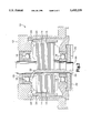
- FIG. 2 is a side cutaway view of an electric motor employing the flex circuit of the present invention.
- FIG. 3 is a top view of the flex circuit shown in FIG. 2.
- FIG. 4 is a bottom view of the flex circuit shown in FIG. 3 inserted into the motor construction of FIG. 2.
- an electric motor 10 includes a rotary hub 12 and wound stators 14 which each include a tooth 15 wrapped with a coil 14a.
- the rotary hub 12 is supported by upper bearings 16 and lower bearings 18.
- a hollow shaft 20 is coupled to the bearings 16 and 18 along their inner races.
- the hub 12 includes a single multiple pole ring magnet 24 which is held within a magnet sleeve 26. In actual operation the hub 12 and the associated magnet 24 rotates about the shaft 20 supported by the bearings 16 and 18.
- the shaft 20 includes an annular end cap 28 and an annular base portion 30.
- a one piece flex circuit 32 extends from underneath the base portion 30 through a slot or groove 34 milled into the shaft 20 in a direction generally parallel to its axis along the inside of a wound stator 14.
- the flex circuit 32 emerges from the slot 34 adjacent the coil 14a of one of the stator teeth 15.
- the end tip 40 (refer to FIG. 3) of the flex circuit 32 is affixed to the top of a stator coil 14a by adhesive or the like.
- the tip portion 40 includes three soldering points 42 which are available for connection to the stator coils 15 by wires or the like (not shown).
- the flex circuit 32 includes circuit runs 44 which are imprinted on a thin elongate narrow strip of PC material.
- a land portion 46 which includes three large contact pads 48 situated at the ends of generally radial arms 50 which reside in wells 49 milled into the base portion 30 which generally surround the shaft 20.
- the contact pads 48 are available for connection to the motor drive electronics (not shown) by any conventional means such as press fitting terminals into the wells 49.
- solder pads 48 are arranged with the contact pads facing downward in the wells 49 in the base portion 30. It is a relatively simple task to thread the lead portion of the flex circuit 32 through the milled slot 34 along the inside the wound stator 14 in order to position the tip 40 so that it may be affixed to the top of one of the coils 14a. This is a significant simplification of the motor fabrication process and provides a strong one-piece link between the motor's stator coils and the drive electronics.
Abstract
Description
Claims (7)
Priority Applications (1)
| Application Number | Priority Date | Filing Date | Title |
|---|---|---|---|
| US08/277,203 US5493159A (en) | 1994-07-19 | 1994-07-19 | Flex circuit for electric motor |
Applications Claiming Priority (1)
| Application Number | Priority Date | Filing Date | Title |
|---|---|---|---|
| US08/277,203 US5493159A (en) | 1994-07-19 | 1994-07-19 | Flex circuit for electric motor |
Publications (1)
| Publication Number | Publication Date |
|---|---|
| US5493159A true US5493159A (en) | 1996-02-20 |
Family
ID=23059847
Family Applications (1)
| Application Number | Title | Priority Date | Filing Date |
|---|---|---|---|
| US08/277,203 Expired - Lifetime US5493159A (en) | 1994-07-19 | 1994-07-19 | Flex circuit for electric motor |
Country Status (1)
| Country | Link |
|---|---|
| US (1) | US5493159A (en) |
Cited By (17)
| Publication number | Priority date | Publication date | Assignee | Title |
|---|---|---|---|---|
| US6121701A (en) * | 1997-06-02 | 2000-09-19 | Seagate Technology Llc | Snap on flexible printed circuit connector |
| US6215616B1 (en) * | 1999-01-04 | 2001-04-10 | Western Digital Corporation | Disk drive spindle motor with wire guide insert |
| US6300739B1 (en) | 1999-12-06 | 2001-10-09 | Hr Textron Inc. | Low cost limited angle torque DC brushless servomotor and method for fabricating thereof |
| SG84544A1 (en) * | 1998-09-02 | 2001-11-20 | Ibm | Cordless compression motor connector for a hard disk drive |
| US6497035B1 (en) | 1999-12-06 | 2002-12-24 | Hr Textron, Inc. | Hall position sensor |
| US20050018352A1 (en) * | 2003-07-24 | 2005-01-27 | Samsung Electronics Co., Ltd. | Flexible printed circuit for spindle motor and disk drive having the same |
| US20070046127A1 (en) * | 2005-08-23 | 2007-03-01 | Seagate Technology Llc | Motor assembly with an integrated flexible printed circuit |
| EP1793476A1 (en) * | 2005-12-01 | 2007-06-06 | Wilo Ag | Centrifugal pump with air-gap sleeve |
| US8466767B2 (en) | 2011-07-20 | 2013-06-18 | Honeywell International Inc. | Electromagnetic coil assemblies having tapered crimp joints and methods for the production thereof |
| US8572838B2 (en) | 2011-03-02 | 2013-11-05 | Honeywell International Inc. | Methods for fabricating high temperature electromagnetic coil assemblies |
| US8754735B2 (en) | 2012-04-30 | 2014-06-17 | Honeywell International Inc. | High temperature electromagnetic coil assemblies including braided lead wires and methods for the fabrication thereof |
| US8860541B2 (en) | 2011-10-18 | 2014-10-14 | Honeywell International Inc. | Electromagnetic coil assemblies having braided lead wires and methods for the manufacture thereof |
| US9027228B2 (en) | 2012-11-29 | 2015-05-12 | Honeywell International Inc. | Method for manufacturing electromagnetic coil assemblies |
| US9076581B2 (en) | 2012-04-30 | 2015-07-07 | Honeywell International Inc. | Method for manufacturing high temperature electromagnetic coil assemblies including brazed braided lead wires |
| US9722464B2 (en) | 2013-03-13 | 2017-08-01 | Honeywell International Inc. | Gas turbine engine actuation systems including high temperature actuators and methods for the manufacture thereof |
| US10724574B2 (en) * | 2018-05-31 | 2020-07-28 | Minebea Mitsumi Inc. | Bearing device |
| US11431210B2 (en) | 2018-08-02 | 2022-08-30 | Regal Beloit America, Inc. | Lamination, stator and electric motor having tip pairs for stator teeth |
Citations (5)
| Publication number | Priority date | Publication date | Assignee | Title |
|---|---|---|---|---|
| US4476404A (en) * | 1983-09-23 | 1984-10-09 | Tandon Corporation | Flexible conductor for supplying current to a pivotally movable electrical element |
| US5023498A (en) * | 1989-07-17 | 1991-06-11 | Teac Corporation | Flexible circuit board for motor position adjustment |
| US5138209A (en) * | 1990-03-01 | 1992-08-11 | Nippon Densan Corporation | Spindle motor |
| US5256922A (en) * | 1991-04-12 | 1993-10-26 | Nippon Densan Corporation | Spindle motor |
| US5313128A (en) * | 1993-02-03 | 1994-05-17 | Seagate Technology, Inc. | Lead wire elimination for enclosed spindle motor |
-
1994
- 1994-07-19 US US08/277,203 patent/US5493159A/en not_active Expired - Lifetime
Patent Citations (5)
| Publication number | Priority date | Publication date | Assignee | Title |
|---|---|---|---|---|
| US4476404A (en) * | 1983-09-23 | 1984-10-09 | Tandon Corporation | Flexible conductor for supplying current to a pivotally movable electrical element |
| US5023498A (en) * | 1989-07-17 | 1991-06-11 | Teac Corporation | Flexible circuit board for motor position adjustment |
| US5138209A (en) * | 1990-03-01 | 1992-08-11 | Nippon Densan Corporation | Spindle motor |
| US5256922A (en) * | 1991-04-12 | 1993-10-26 | Nippon Densan Corporation | Spindle motor |
| US5313128A (en) * | 1993-02-03 | 1994-05-17 | Seagate Technology, Inc. | Lead wire elimination for enclosed spindle motor |
Cited By (25)
| Publication number | Priority date | Publication date | Assignee | Title |
|---|---|---|---|---|
| US6528914B2 (en) * | 1997-06-02 | 2003-03-04 | Seagate Technology Llc | Snap on flexible printed circuit connector |
| US6121701A (en) * | 1997-06-02 | 2000-09-19 | Seagate Technology Llc | Snap on flexible printed circuit connector |
| SG84544A1 (en) * | 1998-09-02 | 2001-11-20 | Ibm | Cordless compression motor connector for a hard disk drive |
| US6433956B1 (en) * | 1998-09-02 | 2002-08-13 | International Business Machines Corporation | Cordless compression motor connector for a hard disk drive |
| US6215616B1 (en) * | 1999-01-04 | 2001-04-10 | Western Digital Corporation | Disk drive spindle motor with wire guide insert |
| US6300739B1 (en) | 1999-12-06 | 2001-10-09 | Hr Textron Inc. | Low cost limited angle torque DC brushless servomotor and method for fabricating thereof |
| US6497035B1 (en) | 1999-12-06 | 2002-12-24 | Hr Textron, Inc. | Hall position sensor |
| US7187518B2 (en) * | 2003-07-24 | 2007-03-06 | Samsung Electronics Co., Ltd. | Flexible printed circuit for spindle motor and disk drive having the same |
| US20050018352A1 (en) * | 2003-07-24 | 2005-01-27 | Samsung Electronics Co., Ltd. | Flexible printed circuit for spindle motor and disk drive having the same |
| US20090229107A1 (en) * | 2005-08-23 | 2009-09-17 | Seagate Technology Llc | Motor Assembly with an Integrated Flexible Printed Circuit |
| US7550890B2 (en) | 2005-08-23 | 2009-06-23 | Seagate Technology Llc | Motor assembly with an integrated flexible printed circuit |
| US20070046127A1 (en) * | 2005-08-23 | 2007-03-01 | Seagate Technology Llc | Motor assembly with an integrated flexible printed circuit |
| US8046904B2 (en) | 2005-08-23 | 2011-11-01 | Seagate Technology | Motor assembly method with an integrated flexible printed circuit |
| EP1793476A1 (en) * | 2005-12-01 | 2007-06-06 | Wilo Ag | Centrifugal pump with air-gap sleeve |
| US9508486B2 (en) | 2011-03-02 | 2016-11-29 | Honeywell International Inc. | High temperature electromagnetic coil assemblies |
| US8572838B2 (en) | 2011-03-02 | 2013-11-05 | Honeywell International Inc. | Methods for fabricating high temperature electromagnetic coil assemblies |
| US8466767B2 (en) | 2011-07-20 | 2013-06-18 | Honeywell International Inc. | Electromagnetic coil assemblies having tapered crimp joints and methods for the production thereof |
| US8860541B2 (en) | 2011-10-18 | 2014-10-14 | Honeywell International Inc. | Electromagnetic coil assemblies having braided lead wires and methods for the manufacture thereof |
| US8754735B2 (en) | 2012-04-30 | 2014-06-17 | Honeywell International Inc. | High temperature electromagnetic coil assemblies including braided lead wires and methods for the fabrication thereof |
| US9076581B2 (en) | 2012-04-30 | 2015-07-07 | Honeywell International Inc. | Method for manufacturing high temperature electromagnetic coil assemblies including brazed braided lead wires |
| US9027228B2 (en) | 2012-11-29 | 2015-05-12 | Honeywell International Inc. | Method for manufacturing electromagnetic coil assemblies |
| US9653199B2 (en) | 2012-11-29 | 2017-05-16 | Honeywell International Inc. | Electromagnetic coil assemblies having braided lead wires and/or braided sleeves |
| US9722464B2 (en) | 2013-03-13 | 2017-08-01 | Honeywell International Inc. | Gas turbine engine actuation systems including high temperature actuators and methods for the manufacture thereof |
| US10724574B2 (en) * | 2018-05-31 | 2020-07-28 | Minebea Mitsumi Inc. | Bearing device |
| US11431210B2 (en) | 2018-08-02 | 2022-08-30 | Regal Beloit America, Inc. | Lamination, stator and electric motor having tip pairs for stator teeth |
Similar Documents
| Publication | Publication Date | Title |
|---|---|---|
| US5493159A (en) | Flex circuit for electric motor | |
| US4540906A (en) | Stator assembly for permanent magnet rotary device | |
| CN101153793B (en) | Resolver and brushless motor | |
| KR910003916Y1 (en) | Small-sized motor | |
| US4724346A (en) | Permanent magnet-excited external rotor motor | |
| EP0310035B1 (en) | A stator for use in a brushless motor | |
| US6528914B2 (en) | Snap on flexible printed circuit connector | |
| JPH04317535A (en) | Spindle motor | |
| JPH0674064U (en) | Magnetic disk drive | |
| JP3410156B2 (en) | Spindle motor | |
| JP3376327B2 (en) | Spindle motor | |
| JPH04304137A (en) | Spindle motor | |
| JPS608526Y2 (en) | motor device | |
| US5955815A (en) | Stator of direct drive motor | |
| JP2559193Y2 (en) | Lead wire holder | |
| KR0137049Y1 (en) | Flat type coreless motor for driving coil | |
| JP3043776U (en) | Controller integrated brushless motor | |
| JPH0214314Y2 (en) | ||
| JPH0723017Y2 (en) | Motor lead wire holder | |
| JPH03277157A (en) | Spindle motor | |
| KR200232342Y1 (en) | FPC structure for power connection of breathless motor | |
| KR0160566B1 (en) | Motors for stator core of assembler | |
| JP3667454B2 (en) | Coil wire connection structure of spindle motor | |
| JP2553997Y2 (en) | Magnetic disk drive | |
| JPH05966Y2 (en) |
Legal Events
| Date | Code | Title | Description |
|---|---|---|---|
| AS | Assignment |
Owner name: SYNEKTRON CORPORATION, OREGON Free format text: ASSIGNMENT OF ASSIGNORS INTEREST;ASSIGNOR:NORRIS, RUSSELL HUGHES;REEL/FRAME:007084/0167 Effective date: 19940715 |
|
| STCF | Information on status: patent grant |
Free format text: PATENTED CASE |
|
| FPAY | Fee payment |
Year of fee payment: 4 |
|
| FPAY | Fee payment |
Year of fee payment: 8 |
|
| AS | Assignment |
Owner name: HUSKO, INC., CALIFORNIA Free format text: MERGER;ASSIGNOR:SYNEKTRON CORPORATION;REEL/FRAME:017344/0076 Effective date: 19970320 |
|
| AS | Assignment |
Owner name: SAE MAGNETICS (HK) LTD., HONG KONG Free format text: ASSIGNMENT OF ASSIGNORS INTEREST;ASSIGNOR:HUSKO, INC.;REEL/FRAME:017656/0301 Effective date: 20060411 |
|
| FPAY | Fee payment |
Year of fee payment: 12 |