US5495528A - Digital telephone control interface system - Google Patents
Digital telephone control interface system Download PDFInfo
- Publication number
- US5495528A US5495528A US08/348,287 US34828794A US5495528A US 5495528 A US5495528 A US 5495528A US 34828794 A US34828794 A US 34828794A US 5495528 A US5495528 A US 5495528A
- Authority
- US
- United States
- Prior art keywords
- telephone
- key
- keys
- user
- switching network
- Prior art date
- Legal status (The legal status is an assumption and is not a legal conclusion. Google has not performed a legal analysis and makes no representation as to the accuracy of the status listed.)
- Expired - Lifetime
Links
Images

Classifications
-
- H—ELECTRICITY
- H04—ELECTRIC COMMUNICATION TECHNIQUE
- H04M—TELEPHONIC COMMUNICATION
- H04M1/00—Substation equipment, e.g. for use by subscribers
- H04M1/247—Telephone sets including user guidance or feature selection means facilitating their use
- H04M1/2473—Telephone terminals interfacing a personal computer, e.g. using an API (Application Programming Interface)
-
- H—ELECTRICITY
- H04—ELECTRIC COMMUNICATION TECHNIQUE
- H04M—TELEPHONIC COMMUNICATION
- H04M1/00—Substation equipment, e.g. for use by subscribers
- H04M1/253—Telephone sets using digital voice transmission
-
- Y—GENERAL TAGGING OF NEW TECHNOLOGICAL DEVELOPMENTS; GENERAL TAGGING OF CROSS-SECTIONAL TECHNOLOGIES SPANNING OVER SEVERAL SECTIONS OF THE IPC; TECHNICAL SUBJECTS COVERED BY FORMER USPC CROSS-REFERENCE ART COLLECTIONS [XRACs] AND DIGESTS
- Y10—TECHNICAL SUBJECTS COVERED BY FORMER USPC
- Y10S—TECHNICAL SUBJECTS COVERED BY FORMER USPC CROSS-REFERENCE ART COLLECTIONS [XRACs] AND DIGESTS
- Y10S379/00—Telephonic communications
- Y10S379/914—Programmable telephone component
- Y10S379/915—Soft key
Definitions
- the present invention relates to a telephone control interface system for use with digital feature telephones (DFTs) that are coupled to a programmable computer control, and more particularly to such telephone control interfaces that selectively mask, monitor, supplement and route the key depressions at the DFT as directed by the computer control.
- DFTs digital feature telephones
- DFTs digital feature telephones
- Many digital feature telephones are no longer limited in their operations to merely receive and transmit telephone messages. Rather, many DFTs contain both logic and memory circuits that allow the DFTs to perform preprogrammed functions. For example, many DFTs are capable of storing commonly dialed telephone numbers within a memory, whereby a telephone number held in memory can be recalled from the memory and forwarded to a telephone switching exchange by a single key depression.
- Wrongful key events may be inadvertently entered into a telephone system when a novice user is first trained in how to properly utilize the system.
- it is not uncommon for telephones to have specialized keys that perform various desirable functions such as the storage and retrieval of commonly used numbers from memory, the transfer of a phone call from one telephone to another, the interconnecting of telephones for conference calls, placing a caller on hold, and so on.
- many telephone systems now utilize DFTs that are so complex in their function, that the purpose of the keys on the telephone keypad are no longer self evident. Consequently, instructions and/or training is required to learn how to properly utilize all the features available within the telephone system.
- the present invention is a digital telephone control interface system for selectively providing a computer control to a digital feature telephone and the corresponding method of masking selected keys on the digital feature telephone with the computer control.
- the present invention digital telephone control interface system interconnects a programmable central processing unit (CPU) or host computer to an existing telephone system, wherein at least one digital feature telephone is coupled to a telephone switching network.
- the CPU selectively masks keys present on the digital feature telephone in accordance with the application software being run by the CPU. Once selected keys are masked, key events generated by a person's utilization of the masked keys are not directly acted upon by the digital feature telephone or the telephone switching network. Rather, key events from masked keys are received, and responded to, solely by the CPU.
- Masked key events received by the CPU are under the sole control of the CPU and can be manipulated in any manner as directed by the software application being run by the CPU.
- the CPU may suppress a key event if a wrongful key event is entered by a user, thereby preventing that key event from being responded to by the telephone system. Additionally, the CPU may delay, alter or enhance the key events entered, adding to the efficiency at which a user may utilize the telephone system.
- the CPU may also dynamically interact with user operation of the telephone system so as to assist the user in performing a desired operation.
- many digital feature telephones include light emitting diodes (LEDs) that correspond to specific function keys on the telephone keypad. If the application software being run by the CPU masks such a function key, the CPU is provided with full control over the LEDs that correspond to the masked function keys. Hence, the LED may be caused to blink or be pulsed according to CPU control.
- the digital feature telephone includes a liquid crystal display (LCD)
- the CPU may be provided with the control of the LCD.
- the CPU also may be coupled to a video display monitor such as a computer screen. By selectively controlling the LEDs or the video display monitor, or the LCD, the CPU can employ desired responses sufficient to accommodate the typical situations encountered in use of the telephone system. As such, the CPU may dynamically instruct or assist a user in performing desired operations within the telephone system.
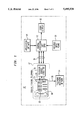
- FIG. 1 is a block diagram of one exemplary embodiment of the present invention telephone control interface system shown in conjunction with a digital feature telephone;
- FIG. 2 is a logic diagram detailing the method of operation for the present invention telephone control interface system.
- DFT 12 includes a standard twelve key keypad 18 typical of conventional digital feature telephones.
- DFT 12 also includes multiple function keys 20 that are dedicated in their operation to control the various preprogrammed features available through the DFT 12.
- the function keys 20 may control such preprogrammed features as retrieving and storing numbers from memory, transferring calls between DFTs, placing a call on hold or any other known function that may be found in a conventional DFT.
- DFT 12 also includes a liquid crystal display (LCD) 24 or other display.
- LCD liquid crystal display
- an LCD 24 on a DFT 12 can be used to display various information to a user of DFT 12, such as visually displaying the numbers entered via keypad keys 18, time elapsed during a call, date, and other common information.
- DFT 12 The features controlled by function keys 20, as well as the operation of LEDs 22 and LCD 24 are controlled within DFT 12 by telephone control circuitry 28.
- the telephone control circuitry 28 contains both the logic and memory circuits needed to support the specific features contained within DFT 12.
- Conventionally, such telephone control circuitry 28 is associated with the telephone subset where it may be contained within the housing that defines DFT 12 or may be separately housed adjacent to DFT 12.
- CPU 16 can be any programmable microprocessor. It should therefore be understood that CPU 16 may be a dedicated unit, such as a personal computer (PC), or CPU 16 may include circuitry contained within DFT 12 itself. In the preferred embodiment, CPU 16 is a personal computer that is separate from the DFT 12. As such, a communications link 30 capable of transmitting digital data is employed to interconnect DFT 12 to CPU 16. Although any known communications link may be used, the preferred embodiment utilizes an RS-232 interconnection. Such a communications link is desirable in the preferred embodiment but would not be required in an alternate embodiment should CPU 16 be formed directly into DFT 12.
- PC personal computer
- CPU 16 is coupled to a visual display 32 such as a CRT which is preferably the video monitor of the personal computer.
- a visual display 32 such as a CRT which is preferably the video monitor of the personal computer.
- the video monitor could be used to display text and graphics to the user as generated by CPU 16.
- a variable input means 33 such as a computer keyboard, dedicated touchpad, mouse or the like may be coupled to CPU 16 so CPU 16 may be accessed by an operator.
- CPU 16 may utilize the LCD 24 of DFT 12 in place and stead of the computer video monitor.
- text and graphics displayed by CPU 16 may be displayed on LCD 24.
- CPU 16 may be accessed by utilizing the keypads keys 18, function keys 20, and specialized keys 21 present on DFT 12 in place and stead of a separate variable input means 33.
- DFT 12 is also coupled to a telephone switching network 14 via a phone line 36.
- the telephones switching network 14 may be a public access exchange or a private branch exchange.
- the phone line connection between a telephone and the telephone switching network allows the telephone to receive and generate calls or activate features within the systems network.
- digital telephone interface system 10 the application software 34 run by CPU 16 selectively masks keypad keys 18, function keys 20 and specialized keys 21 on DFT 12.
- a key event created by the depression of such a masked key is not directly acted upon by the telephone control circuitry 28 nor is such a key event directly transmitted to telephone switching network 14. Rather, if a key is masked by the application software 34 being run by CPU 16, a key event corresponding to such a masked key is directed solely to CPU 16, wherein CPU 16 may direct the key event to the telephone control circuitry 28 and/or telephone switching network 14 as determined by application software 34.
- the masking of a keypad key 18, function key 20 or specialized key 21, is selectively controlled by the application program 34 being run by CPU 16. If a particular keypad key 18, function key 20 or specialized key 21 is not masked by the application program 34 being run by CPU 16, the key event generated by depression of such key is directly acted upon by the telephone control circuitry 28 of DFT 12, and/or directed to telephone switching network 14 in the conventional manner. Similarly, if CPU 16 were not enabled, no keypad 18, function key 20 or specialized key 21 would be masked and all resulting key events would be directly reacted to by the telephone control circuitry 28 of DFT 12 and the telephone switching network 14 in a conventional manner.
- Application software 34 to be run by CPU 16 is selected depending upon the needs of a particular telephone system and the task to be performed by a user within. the telephone system. By masking selected key events from keypad keys 18, function keys 20 and specialized keys 21, CPU 16 responds to key events before they are responded to by the telephone control circuitry 28. This operation prevents the key event from being forwarded to the telephone exchange network 14. Under the direction of application software 34, CPU 16 can ignore a key event, delay a key event, enhance a key event, alter a key event and/or dynamically interact with DFT 12 as a result of the key event so as to instruct or assist the user in an operation.
- FIG. 2 a block diagram is shown illustrating the interactions of the digital telephone control interface system with DFT 12 and telephone switching network 14.
- the first step in the operation is to select the desired application software 34, as shown by box 50.
- the appropriate application program is selected by loading a desired application software into the personal computer or retrieving the desired application program from the memory of the personal computer.
- variable input means 33 which may be the computer keyboard, mouse or the like
- CPU 16 was not embodied as a personal computer, but rather was directly formed into the circuitry of DFT 12, it should be understood that the desired application software 34 could be selected and run by utilizing selected keypad keys 18, function keys 20 and/or specialized keys 21 on DFT 12. For example, by entering a predetermined sequence or code into keypad keys 18, function keys 20 and/or specialized keys 21, a desired application program could be recalled from an internal memory source and run by CPU 16.
- the present invention digital telephone control interface system 10 may be configured to utilize only one application software program which is automatically run by CPU 16 when CPU 16 is enabled.
- CPU 16 masks selected keypad keys 18, function keys 20 and specialized keys 21 on DFT 12.
- the CPU controlled masking of a key can be accomplished in any known manner. However, in the preferred embodiment, CPU 16 masks the various keys of DFT 12 by creating a binary field where each binary digit in the binary field corresponds to one of keys present on DFT 12. As such, the number of binary digits in the binary field match or exceed the total number of keys on DFT 12. Nominally, all the binary digits within the binary field are set at (0). However, as the application software 34 determines that a specified key is to be masked, the binary digit corresponding to that specified key is set at one (1).
- the structure of this masking command, as formed by CPU 16, may be as shown below:
- the binary field created by CPU 16 is directed to the telephone control circuitry 28 of DFT 12 where it acts as a masking command. DFT 12 then executes the masking command, masking selected keypad keys 18, function keys 20 and/or specialized keys 21 contained within the masking command that have a binary value of one (1). It should be understood that although the above binary value approach to masking DFT keypad keys 18, function keys 20 and specialized keys 21, is preferred, other codes and operations can be employed.
- a user can begin to use the DFT 12 to perform a desired task, as indicated by box 54.
- keypad keys 18, function keys 20 and specialized keys 21, key events result.
- box 56 if a key event corresponds to a key that has not been masked the key event is either directly forwarded to the telephone switching network 14 (as indicated by line 55) or the key event is directly acted upon by the telephone control circuitry 28 of DFT 12 (as indicated by line 57). Consequently, if a key is not masked the key event from the unmasked key is acted upon in a conventional manner.
- box 58 if a user depresses a key on DFT 12 that has been masked by CPU 16, the CPU 16 receives the masked key event and responds to the key event according to the running application software 34.
- CPU 16 The operations performed by CPU 16 in response to a received masked key event are controlled by the application software 34 being run by CPU 16. Depending upon the application software 34 selected, the CPU 16 may suppress, enhance, alter or delay the key event entered. Additionally, CPU 16 may interact with the user of the DFT 12 by selectively controlling the LEDs 22 and LCD 24 on the DFT 12 (as indicated by line 59) or providing visual information to the user, via the video monitor 32 (as indicated by line 61). For example, if application software 34 were selected to assist a novice user in learning to properly operate a complicated telephone system, the application software 34 may mask all the keys available on DFT 12. The CPU 16 may then begin to instruct the user in how to properly operate the different functions available on DFT 12.
- the CPU 16 may generate instructions and/or graphical illustrations on the video monitor 32, which may instruct a user in how to utilize the keypad keys 18, function keys 20 and specialized keys 21. In addition to the information set forth on the video monitor 32, the CPU 16 may provide messages to be displayed on the LCD 24. Furthermore, CPU 16 may selectively control the LEDs 22 that correspond to the masked keys. The CPU 16 may create any desired blinking sequence in the LEDs 22 it controls. As such, CPU 16 may selectively energize or blink the LEDs 22 to help a user locate any key associated with an LED 22.
- CPU 16 By selectively masking the keys, CPU 16 intercepts a given key event before that key event is responded to by the telephone switching network 14 or the telephone control circuitry 28. As such, CPU 16 may suppress a received key event, enhance the key event, alter the key event or delay the key event until selective criteria occur. For instance, if application software 34 were chosen to help a novice user learn the features of a given telephone system, CPU 16 may mask all the keys on DFT 12. As the user began using DFT 12, CPU 16 may interact with the user, via the video monitor 32, LEDs 22 and/or LCD 24, to instruct the user as to which keys must be used to accomplish a desired function.
- CPU 16 can suppress the resulting key event, inform the user as to his error and instruct the user as to which key on DFT 12 is proper. If a user depressed a proper key, CPU 16 may so inform the user and forward the key event to either the telephone switching network 14 or the telephone control circuitry 28, wherein the key event could be acted upon in a conventional manner. Furthermore, if a user were entering a large sequence of key events into DFT 12, such as a telephone number or security code number, CPU 16 may delay the key events by storing the key event sequence in memory. After the user has completed the desired key event sequence, CPU 16 may display the sequence to the user on the video monitor 32 and/or LCD 24.
- the present invention digital telephone control interface system 10 can be used to prevent wrongful key events from being reacted to by the telephone control circuitry 28 or telephone switching network 14, thereby preventing the accidental misuse of DFT 12 and unnecessary loading of telephone switching network 14.
- CPU 16 may also enhance or alter the key events received.
- CPU 16 may provide a complex string of key events in response to a single received key event, thereby allowing large key event sequences, such as telephone numbers or the like to be generated by the depression of a single key.
- Another powerful application of the present invention digital telephone control interface system 10 is one wherein CPU 16, as directed by application software 34, alters or expands upon the key events entered by the user in a new manner. For instance, the user could run an application program 34 that allows the user to dial by name rather than by phone number, utilizing the letters conventionally found on the keypad keys 18 of a DFT 12.
- CPU 16 can mask the keypad keys 18 and match the letters entered to telephone numbers stored within the memory of CPU 16. CPU 16 can then generate the proper key event sequence to dial the desired individual. When applied to a telephone system contained within a single company, a user can dial any person merely by dialing the person's name. As such, a user does not have to remember or reference a person's telephone number in order to dial the person.
- the key events created by the operator would not be responded to by DFT 12 or forwarded to telephone switching network 12. Rather, the key events created by the operator would be received only by CPU 16 where CPU 16 could respond to the key events and assist the operator in learning the telephone system. As such, both the telephone control circuitry 28 of DFT 12 and the telephone switching network 14 would remain unaffected.
- the application software 34 may mask the key entries entered by the operator, check the accuracy of those key entries and finally cause DFT 12 to respond to the key events or forward those key events to the telephone switching network 14 so as to actually produce the desired function.
- the present invention telephone control interface system 10 can be applied to any application where it is desired to assist, direct, confirm or alter an operator's use of a DFT 12 before the operator's actions are actually responded to by DFT 12 or forwarded to telephone switching network 14.
- the present invention telephone control interface system 10 can be used to confirm that a proper telephone number, security code number or the like has been properly dialed, by masking the dialed entry until the dialed entry is confirmed by the operator, at which time that dialed entry can be responded to by the telephone 12 or forwarded to the telephone switching network 14 with confidence.
- the present invention telephone control interface system is a computer controlled system that acts as an intermediary in the coupling of a telephone's keypad to the telephone and the interconnection of the telephone to a switching network.
- the present invention telephone control interface system can be programmed to instruct, assist, confirm or alter the key events generated by an operator in properly utilizing most any digital feature telephone. All variations and modifications to the present invention, achievable by a person skilled in the art, are intended to be included within the scope of the invention as defined by the appended claims.
Abstract
Description
______________________________________
          BINARY      KEY MASKED/
BYTE #    VALUE       LED CONTROLLED
______________________________________
1         0000 0001   1
1         0000 0010   2
1         0000 0011   1 and 2
.         .
.         .
.         .
N         XXXX XXXX   Enough bytes to cover
                      all phone keys
______________________________________
Claims (20)
Priority Applications (1)
| Application Number | Priority Date | Filing Date | Title |
|---|---|---|---|
| US08/348,287 US5495528A (en) | 1992-08-25 | 1994-11-30 | Digital telephone control interface system |
Applications Claiming Priority (2)
| Application Number | Priority Date | Filing Date | Title |
|---|---|---|---|
| US93499292A | 1992-08-25 | 1992-08-25 | |
| US08/348,287 US5495528A (en) | 1992-08-25 | 1994-11-30 | Digital telephone control interface system |
Related Parent Applications (1)
| Application Number | Title | Priority Date | Filing Date |
|---|---|---|---|
| US93499292A Continuation | 1992-08-25 | 1992-08-25 |
Publications (1)
| Publication Number | Publication Date |
|---|---|
| US5495528A true US5495528A (en) | 1996-02-27 |
Family
ID=25466408
Family Applications (1)
| Application Number | Title | Priority Date | Filing Date |
|---|---|---|---|
| US08/348,287 Expired - Lifetime US5495528A (en) | 1992-08-25 | 1994-11-30 | Digital telephone control interface system |
Country Status (1)
| Country | Link |
|---|---|
| US (1) | US5495528A (en) |
Cited By (16)
| Publication number | Priority date | Publication date | Assignee | Title |
|---|---|---|---|---|
| US6069940A (en) * | 1997-09-19 | 2000-05-30 | Siemens Information And Communication Networks, Inc. | Apparatus and method for adding a subject line to voice mail messages |
| US6370238B1 (en) | 1997-09-19 | 2002-04-09 | Siemens Information And Communication Networks Inc. | System and method for improved user interface in prompting systems |
| US6584181B1 (en) | 1997-09-19 | 2003-06-24 | Siemens Information & Communication Networks, Inc. | System and method for organizing multi-media messages folders from a displayless interface and selectively retrieving information using voice labels |
| US6760410B1 (en) * | 1998-09-04 | 2004-07-06 | Samsung Electronics Co., Ltd. | Computer having automatic answering state displaying and processing functions and method of processing automatic answering |
| US6862347B1 (en) * | 1999-01-28 | 2005-03-01 | Siemens Communications, Inc. | Method and apparatus for extending a telephone's capabilities |
| US20050254784A1 (en) * | 2004-05-12 | 2005-11-17 | Funai Electric Co., Ltd. | Video signal reproducing apparatus |
| US20060025175A1 (en) * | 1999-12-01 | 2006-02-02 | Silverbrook Research Pty Ltd | Dialling a number via a coded surface |
| US20060109620A1 (en) * | 2000-05-30 | 2006-05-25 | Kim Darren C | Lightweight, energy-efficient, detachable computer light |
| US20060258346A1 (en) * | 1999-12-01 | 2006-11-16 | Silverbrook Research Pty Ltd | Method for communication device control using coded marks |
| US7676034B1 (en) | 2003-03-07 | 2010-03-09 | Wai Wu | Method and system for matching entities in an auction |
| US7894595B1 (en) | 2002-03-07 | 2011-02-22 | Wai Wu | Telephony control system with intelligent call routing |
| US7916858B1 (en) | 2001-06-25 | 2011-03-29 | Toby Heller | Agent training sensitive call routing system |
| US8300798B1 (en) | 2006-04-03 | 2012-10-30 | Wai Wu | Intelligent communication routing system and method |
| US10567975B2 (en) | 2005-10-04 | 2020-02-18 | Hoffberg Family Trust 2 | Multifactorial optimization system and method |
| US10718031B1 (en) | 2014-11-03 | 2020-07-21 | Wai Wu | Method and system for matching entities in an auction |
| US10943273B2 (en) | 2003-02-05 | 2021-03-09 | The Hoffberg Family Trust 2004-1 | System and method for determining contingent relevance |
Citations (7)
| Publication number | Priority date | Publication date | Assignee | Title |
|---|---|---|---|---|
| US4578540A (en) * | 1982-12-20 | 1986-03-25 | At&T Bell Laboratories | Telecommunications systems |
| US4720853A (en) * | 1985-07-05 | 1988-01-19 | Melita Electronic Labs, Inc. | Ring signal discriminator |
| JPS63196140A (en) * | 1987-02-09 | 1988-08-15 | Minolta Camera Co Ltd | Telephone control equipment |
| US4860339A (en) * | 1986-08-08 | 1989-08-22 | Dictaphone Corporation | Programmable telephone/dictation terminal and method of operating same |
| US4903289A (en) * | 1987-03-24 | 1990-02-20 | Hashimoto Corporation | Telephone equipment with multiple function |
| US4953202A (en) * | 1985-06-28 | 1990-08-28 | Newell Terence J | Telephone line access control |
| US5109408A (en) * | 1989-11-30 | 1992-04-28 | At&T Bell Laboratories | Arrangement for intentionally blocking telephone calls to predefined destination numbers but allowing such blocking to be selectively overridden |
-
1994
- 1994-11-30 US US08/348,287 patent/US5495528A/en not_active Expired - Lifetime
Patent Citations (7)
| Publication number | Priority date | Publication date | Assignee | Title |
|---|---|---|---|---|
| US4578540A (en) * | 1982-12-20 | 1986-03-25 | At&T Bell Laboratories | Telecommunications systems |
| US4953202A (en) * | 1985-06-28 | 1990-08-28 | Newell Terence J | Telephone line access control |
| US4720853A (en) * | 1985-07-05 | 1988-01-19 | Melita Electronic Labs, Inc. | Ring signal discriminator |
| US4860339A (en) * | 1986-08-08 | 1989-08-22 | Dictaphone Corporation | Programmable telephone/dictation terminal and method of operating same |
| JPS63196140A (en) * | 1987-02-09 | 1988-08-15 | Minolta Camera Co Ltd | Telephone control equipment |
| US4903289A (en) * | 1987-03-24 | 1990-02-20 | Hashimoto Corporation | Telephone equipment with multiple function |
| US5109408A (en) * | 1989-11-30 | 1992-04-28 | At&T Bell Laboratories | Arrangement for intentionally blocking telephone calls to predefined destination numbers but allowing such blocking to be selectively overridden |
Cited By (53)
| Publication number | Priority date | Publication date | Assignee | Title |
|---|---|---|---|---|
| US6370238B1 (en) | 1997-09-19 | 2002-04-09 | Siemens Information And Communication Networks Inc. | System and method for improved user interface in prompting systems |
| US6584181B1 (en) | 1997-09-19 | 2003-06-24 | Siemens Information & Communication Networks, Inc. | System and method for organizing multi-media messages folders from a displayless interface and selectively retrieving information using voice labels |
| US6069940A (en) * | 1997-09-19 | 2000-05-30 | Siemens Information And Communication Networks, Inc. | Apparatus and method for adding a subject line to voice mail messages |
| US6760410B1 (en) * | 1998-09-04 | 2004-07-06 | Samsung Electronics Co., Ltd. | Computer having automatic answering state displaying and processing functions and method of processing automatic answering |
| US7042991B2 (en) | 1999-01-28 | 2006-05-09 | Siemens Communications Inc. | Method and apparatus for extending a telephone's capabilities |
| US6862347B1 (en) * | 1999-01-28 | 2005-03-01 | Siemens Communications, Inc. | Method and apparatus for extending a telephone's capabilities |
| US20050129220A1 (en) * | 1999-01-28 | 2005-06-16 | Siemens Communications, Inc. | Method and apparatus for extending a telephone's capabilities |
| US7904077B2 (en) | 1999-12-01 | 2011-03-08 | Silverbrook Research Pty Ltd | Control of a communications device |
| US7738918B2 (en) | 1999-12-01 | 2010-06-15 | Silverbrook Research Pty Ltd | Sending a message to a number via a coded surface |
| US8290522B2 (en) | 1999-12-01 | 2012-10-16 | Silverbrook Research Pty Ltd | Messaging via a coded business card and mobile telephone |
| US20060258346A1 (en) * | 1999-12-01 | 2006-11-16 | Silverbrook Research Pty Ltd | Method for communication device control using coded marks |
| US7295839B1 (en) | 1999-12-01 | 2007-11-13 | Silverbrook Research Pty Ltd | System and method for controlling a telephone via a computer system and printed control interface |
| US7558598B2 (en) | 1999-12-01 | 2009-07-07 | Silverbrook Research Pty Ltd | Dialling a number via a coded surface |
| US7577428B2 (en) | 1999-12-01 | 2009-08-18 | Silverbrook Research Pty Ltd | Method of enabling telephone control via printed control interface |
| US7580698B2 (en) | 1999-12-01 | 2009-08-25 | Silverbrook Research Pty Ltd | Method for communication device control using coded marks |
| US20090247221A1 (en) * | 1999-12-01 | 2009-10-01 | Silverbrook Research Pty Ltd | Sending A Message To A Number Via A Coded Surface |
| US20090280864A1 (en) * | 1999-12-01 | 2009-11-12 | Silverbrook Research Pty Ltd | Control of a device |
| US20090280793A1 (en) * | 1999-12-01 | 2009-11-12 | Silverbrook Research Pty Ltd | Method Of Controlling A Communications Device |
| US8112072B2 (en) * | 1999-12-01 | 2012-02-07 | Silverbrook Research Pty Ltd | Control of a communications device |
| US20060025175A1 (en) * | 1999-12-01 | 2006-02-02 | Silverbrook Research Pty Ltd | Dialling a number via a coded surface |
| US8095110B2 (en) | 1999-12-01 | 2012-01-10 | Silverbrook Research Pty Ltd | Method for a device to perform a function in response to a command from a printer |
| US7773984B2 (en) | 1999-12-01 | 2010-08-10 | Silverbrook Research Pty Ltd | Method of controlling a communications device |
| US7783280B2 (en) | 1999-12-01 | 2010-08-24 | Silverbrook Research Pty Ltd | Method of enabling a function of a device in response to a command from printer |
| US20100234052A1 (en) * | 1999-12-01 | 2010-09-16 | Silverbrook Research Pty Ltd | Messaging using a coded surface |
| US20100296125A1 (en) * | 1999-12-01 | 2010-11-25 | Silverbrook Research Pty Ltd | Control of a communications device |
| US20100302591A1 (en) * | 1999-12-01 | 2010-12-02 | Silverbrook Research Pty Ltd | Control of a device |
| US8081994B2 (en) | 1999-12-01 | 2011-12-20 | Silverbrook Research Pty Ltd | Messaging using a coded surface |
| US20110122431A1 (en) * | 1999-12-01 | 2011-05-26 | Silverbrook Research Pty Ltd | Control of a communications device |
| US7925299B2 (en) | 1999-12-01 | 2011-04-12 | Silverbrook Research Pty Ltd | Messaging using a coded surface |
| US20060109620A1 (en) * | 2000-05-30 | 2006-05-25 | Kim Darren C | Lightweight, energy-efficient, detachable computer light |
| US7916858B1 (en) | 2001-06-25 | 2011-03-29 | Toby Heller | Agent training sensitive call routing system |
| US8971519B1 (en) | 2001-06-25 | 2015-03-03 | Steven Hoffberg | Agent training sensitive call routing system |
| US9635177B1 (en) | 2001-06-25 | 2017-04-25 | Steven M. Hoffberg | Agent training sensitive call routing system |
| US8582753B1 (en) | 2001-06-25 | 2013-11-12 | Toby Heller | Agent training sensitive call routing system |
| US10447855B1 (en) | 2001-06-25 | 2019-10-15 | Steven M. Hoffberg | Agent training sensitive call routing system |
| US9736308B1 (en) | 2002-03-07 | 2017-08-15 | Wai Wu | Intelligent communication routing |
| US10560579B1 (en) | 2002-03-07 | 2020-02-11 | Wai Wu | Intelligent communication routing |
| US8831205B1 (en) | 2002-03-07 | 2014-09-09 | Wai Wu | Intelligent communication routing |
| US7894595B1 (en) | 2002-03-07 | 2011-02-22 | Wai Wu | Telephony control system with intelligent call routing |
| US11790413B2 (en) | 2003-02-05 | 2023-10-17 | Hoffberg Family Trust 2 | System and method for communication |
| US10943273B2 (en) | 2003-02-05 | 2021-03-09 | The Hoffberg Family Trust 2004-1 | System and method for determining contingent relevance |
| US10237420B1 (en) | 2003-03-07 | 2019-03-19 | Wai Wu | Method and system for matching entities in an auction |
| US9860391B1 (en) | 2003-03-07 | 2018-01-02 | Wai Wu | Method and system for matching entities in an auction |
| US7676034B1 (en) | 2003-03-07 | 2010-03-09 | Wai Wu | Method and system for matching entities in an auction |
| US9456086B1 (en) | 2003-03-07 | 2016-09-27 | Wai Wu | Method and system for matching entities in an auction |
| US7702210B2 (en) * | 2004-05-12 | 2010-04-20 | Funai Electric Co., Ltd. | Video signal reproducing apparatus |
| US20050254784A1 (en) * | 2004-05-12 | 2005-11-17 | Funai Electric Co., Ltd. | Video signal reproducing apparatus |
| US10567975B2 (en) | 2005-10-04 | 2020-02-18 | Hoffberg Family Trust 2 | Multifactorial optimization system and method |
| USRE49334E1 (en) | 2005-10-04 | 2022-12-13 | Hoffberg Family Trust 2 | Multifactorial optimization system and method |
| US9807239B1 (en) | 2006-04-03 | 2017-10-31 | Wai Wu | Intelligent communication routing system and method |
| US8300798B1 (en) | 2006-04-03 | 2012-10-30 | Wai Wu | Intelligent communication routing system and method |
| US10491748B1 (en) | 2006-04-03 | 2019-11-26 | Wai Wu | Intelligent communication routing system and method |
| US10718031B1 (en) | 2014-11-03 | 2020-07-21 | Wai Wu | Method and system for matching entities in an auction |
Similar Documents
| Publication | Publication Date | Title |
|---|---|---|
| US5495528A (en) | Digital telephone control interface system | |
| US4754326A (en) | Method and apparatus for assisting user of information retrieval systems | |
| US5481667A (en) | Method and system for instructing a user of a computer system how to perform application program tasks | |
| US5621789A (en) | Method and system for integrating a plurality of call center agent performance enhancement modules | |
| US5553125A (en) | Telephone apparatus with calling line identification | |
| US5920308A (en) | Keyboard with a wireless remote control receiver and a method of redefining a key function for remote control | |
| US6429855B2 (en) | Computer-telephony integration employing an intelligent keyboard and method for same | |
| US5311577A (en) | Data processing system, method and program for constructing host access tables for integration of telephony data with data processing systems | |
| JPH06309136A (en) | List item of notebook graphical user interface | |
| CA2065131C (en) | Method of defining operation of switching system peripherals | |
| US5454035A (en) | Electronic apparatus | |
| US6628758B1 (en) | System for item selection in a telephony auto-attendant | |
| JPH0376356A (en) | Human voice recognition portable telephone set | |
| US4650932A (en) | Key telephone system | |
| JPS6366623A (en) | Intellectual operation backup system | |
| JPH03108996A (en) | Key telephone system | |
| JPH0262147A (en) | Communication equipment | |
| JPH0298263A (en) | Telephone set with display and private branch exchange system | |
| JPH01318444A (en) | Automatic dialing device | |
| KR20040105503A (en) | Information transmission device that use keyboard and thereof method | |
| JP2889339B2 (en) | A system that provides services using an attendant console | |
| JPH08307559A (en) | Terminal equipment | |
| JPS63249215A (en) | Information processor | |
| KR880012070A (en) | Data entry method of memory phone | |
| JPH086694A (en) | Character input method by ten key |
Legal Events
| Date | Code | Title | Description |
|---|---|---|---|
| STCF | Information on status: patent grant |
Free format text: PATENTED CASE |
|
| FEPP | Fee payment procedure |
Free format text: PAYOR NUMBER ASSIGNED (ORIGINAL EVENT CODE: ASPN); ENTITY STATUS OF PATENT OWNER: LARGE ENTITY |
|
| FPAY | Fee payment |
Year of fee payment: 4 |
|
| FPAY | Fee payment |
Year of fee payment: 8 |
|
| FPAY | Fee payment |
Year of fee payment: 12 |
|
| AS | Assignment |
Owner name: RS MARKETING, L.P.,CALIFORNIA Free format text: MERGER;ASSIGNOR:ROLM SYSTEMS;REEL/FRAME:024202/0730 Effective date: 19920928 |
|
| AS | Assignment |
Owner name: ROLM COMPANY,CALIFORNIA Free format text: MERGER;ASSIGNOR:RS MARKETING, L.P.;REEL/FRAME:024213/0604 Effective date: 19920928 |
|
| AS | Assignment |
Owner name: ROLM COMPANY, INC.,CALIFORNIA Free format text: CERTIFICATE OF INCORPORATION;ASSIGNOR:ROLM COMPANY;REEL/FRAME:024218/0818 Effective date: 19940829 |
|
| AS | Assignment |
Owner name: SIEMENS ROLM COMMUNICATIONS INC.,CALIFORNIA Free format text: CERTIFICATE OF AMENDMENT TO CERTIFICATE OF INCORPORATION;ASSIGNOR:ROLM COMPANY, INC.;REEL/FRAME:024233/0593 Effective date: 19940930 |
|
| AS | Assignment |
Owner name: SIEMENS BUSINESS COMMUNICATION SYSTEMS, INC.,CALIF Free format text: CHANGE OF NAME;ASSIGNOR:SIEMENS ROLM COMMUNICATIONS INC.;REEL/FRAME:024244/0257 Effective date: 19961001 |
|
| AS | Assignment |
Owner name: SIEMENS INFORMATION AND COMMUNICATION NETWORKS, IN Free format text: MERGER;ASSIGNOR:SIEMENS BUSINESS COMMUNICATION SYSTEMS, INC.;REEL/FRAME:024244/0679 Effective date: 19980930 |
|
| AS | Assignment |
Owner name: SIEMENS COMMUNICATIONS, INC.,FLORIDA Free format text: MERGER;ASSIGNOR:SIEMENS INFORMATION AND COMMUNICATION NETWORKS, INC.;REEL/FRAME:024263/0817 Effective date: 20040922 Owner name: SIEMENS COMMUNICATIONS, INC., FLORIDA Free format text: MERGER;ASSIGNOR:SIEMENS INFORMATION AND COMMUNICATION NETWORKS, INC.;REEL/FRAME:024263/0817 Effective date: 20040922 |
|
| AS | Assignment |
Owner name: SIEMENS ENTERPRISE COMMUNICATIONS, INC.,FLORIDA Free format text: ASSIGNMENT OF ASSIGNORS INTEREST;ASSIGNOR:SIEMENS COMMUNICATIONS, INC.;REEL/FRAME:024294/0040 Effective date: 20100304 Owner name: SIEMENS ENTERPRISE COMMUNICATIONS, INC., FLORIDA Free format text: ASSIGNMENT OF ASSIGNORS INTEREST;ASSIGNOR:SIEMENS COMMUNICATIONS, INC.;REEL/FRAME:024294/0040 Effective date: 20100304 |
|
| AS | Assignment |
Owner name: WELLS FARGO TRUST CORPORATION LIMITED, AS SECURITY Free format text: GRANT OF SECURITY INTEREST IN U.S. PATENTS;ASSIGNOR:SIEMENS ENTERPRISE COMMUNICATIONS, INC.;REEL/FRAME:025339/0904 Effective date: 20101109 |
|
| AS | Assignment |
Owner name: UNIFY GMBH & CO. KG, GERMANY Free format text: ASSIGNMENT OF ASSIGNORS INTEREST;ASSIGNOR:UNIFY INC.;REEL/FRAME:036434/0247 Effective date: 20150409 |
|
| AS | Assignment |
Owner name: UNIFY, INC., FLORIDA Free format text: TERMINATION AND RELEASE OF SECURITY INTEREST IN PATENTS;ASSIGNOR:WELLS FARGO TRUST CORPORATION LIMITED;REEL/FRAME:036574/0383 Effective date: 20140929 |
|
| AS | Assignment |
Owner name: ENTERPRISE SYSTEMS TECHNOLOGIES S.A.R.L., LUXEMBOU Free format text: ASSIGNMENT OF ASSIGNORS INTEREST;ASSIGNOR:ENTERPRISE TECHNOLOGIES S.A.R.L. & CO. KG;REEL/FRAME:036987/0803 Effective date: 20141118 Owner name: ENTERPRISE TECHNOLOGIES S.A.R.L. & CO. KG, GERMANY Free format text: DEMERGER;ASSIGNOR:UNIFY GMBH & CO. KG;REEL/FRAME:037008/0751 Effective date: 20140327 |