US5509009A - Video and aural communications system - Google Patents
Video and aural communications system Download PDFInfo
- Publication number
- US5509009A US5509009A US08/065,171 US6517193A US5509009A US 5509009 A US5509009 A US 5509009A US 6517193 A US6517193 A US 6517193A US 5509009 A US5509009 A US 5509009A
- Authority
- US
- United States
- Prior art keywords
- codec
- switch
- coupled
- subsystem
- video
- Prior art date
- Legal status (The legal status is an assumption and is not a legal conclusion. Google has not performed a legal analysis and makes no representation as to the accuracy of the status listed.)
- Expired - Fee Related
Links
Images


Classifications
-
- H—ELECTRICITY
- H04—ELECTRIC COMMUNICATION TECHNIQUE
- H04N—PICTORIAL COMMUNICATION, e.g. TELEVISION
- H04N7/00—Television systems
- H04N7/14—Systems for two-way working
- H04N7/141—Systems for two-way working between two video terminals, e.g. videophone
- H04N7/148—Interfacing a video terminal to a particular transmission medium, e.g. ISDN
-
- H—ELECTRICITY
- H04—ELECTRIC COMMUNICATION TECHNIQUE
- H04Q—SELECTING
- H04Q11/00—Selecting arrangements for multiplex systems
- H04Q11/04—Selecting arrangements for multiplex systems for time-division multiplexing
- H04Q11/0428—Integrated services digital network, i.e. systems for transmission of different types of digitised signals, e.g. speech, data, telecentral, television signals
- H04Q11/0435—Details
-
- Y—GENERAL TAGGING OF NEW TECHNOLOGICAL DEVELOPMENTS; GENERAL TAGGING OF CROSS-SECTIONAL TECHNOLOGIES SPANNING OVER SEVERAL SECTIONS OF THE IPC; TECHNICAL SUBJECTS COVERED BY FORMER USPC CROSS-REFERENCE ART COLLECTIONS [XRACs] AND DIGESTS
- Y10—TECHNICAL SUBJECTS COVERED BY FORMER USPC
- Y10S—TECHNICAL SUBJECTS COVERED BY FORMER USPC CROSS-REFERENCE ART COLLECTIONS [XRACs] AND DIGESTS
- Y10S379/00—Telephonic communications
- Y10S379/908—Multimedia
Definitions
- This invention relates to video services, for example, videoconferencing, video multimedia remote surveillance.
- a dial-up aural and visual communication system including a telecommunications network, a telecommunications switch connected to the network and a codec subsystem located at the switch and connected to the switch, voice communication equipment of end users associated with the switch being connected directly to the switch and video equipment of end users associated with the switch being connectable to the switch via the codec subsystem, the codec subsystem being shared between the end users and being in the form of a video line-card for the switch.
- a codec subsystem for use with a dial-up aural and visual communications system according to the preceding paragraph, the codec subsystem including one or more codecs, composite video input/output means and means for controlling the operation of the subsystem.
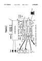
- FIG. 1 is a functional diagram of the inventive arrangement
- FIGS. 2a and 2b illustrate two possible system configurations
- FIGS. 3, 4 and 5 illustrate basic surveillance applications
- FIG. 6 illustrates networked surveillance services
- FIG. 7 illustrates a basic desk-top application
- FIG. 8 illustrates the desk-top service application in greater detail
- FIG. 9 illustrates a networked surveillance application in greater detail
- FIG. 10 illustrates a medium resolution desk-top application
- FIG. 11 illustrates an image grooming service
- FIG. 12 illustrates a local video switching service
- FIG. 13 illustrates an n ⁇ 64 switching service.
- the communication may take one of several forms, such as:
- the quality of service required may vary from application to application.
- the speed of data transfer (and hence image update rate) is not of paramount importance, as long as high resolution image and/or audio are achieved.
- speed is of the essence but resolution is not crucial.
- the ability to vary the bandwidth link to match both the service requirement and permissible costs enables a more cost-effective solution to be put in place and allows more users to gain access to image-based services.
- codec pool or codec subsystem interfaced to a telephone switch (PBX) in order to permit images to be transmitted across the networks accessed by the switch.
- codec pool codec subsystem
- codec subsystem an arrangement of elements including codecs, which may be capable of dealing with various different signal rates or a number of the same rates, whereby flexibility in the service offered is available.
- codec subsystem by closely coupling the codec subsystem to the switch, rather than arranging it adjacent to the subscribers terminals (end-users), the scheduling, control and value-added features supported by the switch can be utilised by the end-user to obtain a higher level of service.
- codecs codec subsystem
- PBX subscribers a cost-effective commercial solution results.
- FIG. 1 is a functional diagram of the proposed arrangement and the end users. It basically comprises a conventional for example, PBX, network switch 1 capable of 64 kbps switching which is shown interfacing to both private circuits and the public switched telephoned network (PSTN).
- PSTN public switched telephoned network
- the switch 1 is shown supporting voice facilities in a conventional manner, however, in addition numerous additional links are indicated in order to permit the switch to support image services. These links are between the switch 1 and the codec subsystem 2 and between the codec subsystem 2 and various video systems 3 consisting of TV cameras with or without associated viewing screens or monitors.
- the codec subsystem 2 is shown as incorporating a number of elements: a p ⁇ 64 k codec 4, a 9.6 k codec 5, an n ⁇ 64 phase aligner 6, a composite video input 7, a local video switch 8, a frame store 9, a conversion algorithm 10, a V.32 modem 11 and a control unit 12. Quite which elements are present for a particular application are determined by that application, as will be apparent from the following description.
- the codec subsystem is connected to the video end user 3 having cameras 13 and screens 14 via, for example, coaxial cables or twisted pair cables 13a.
- the RS449 link is provided for interconnections for video codecs, CAD/CAM, file transfer etc.
- the illustrated links between the codec subsystem 2 and the network switch 1 include 30 B+D lines supporting DASS 11, 2B+D links or HSDM (High Speed Data Module), 2-wire analogue lines and RS232 links. Furthermore there is an RS232 control link between the control unit 12 and the network switch 1. Overall coordination of the two subsystems (switch 1 and codec pool 2) is achieved by the RS232 control link and the control process within the codec subsystem 2.
- the computer terminal 15 may be used to control the codec subsystem to operate as required and to achieve other operations as will be apparent from the following.
- the codec subsystem 2 includes the various elements referred to above in order to be able to provide a number of services for a number of different types of end users.
- the codec subsystem 2 is disposed adjacent to the network switch 1 and may be considered as being in the form of a video line card for the switch. Such a video line card can be placed alongside an existing switch and interconnected to it.
- the codec subsystem specifically covers use at a number of transmission rates from a basic 9.6 kbps rate up to p x 64 kbps (p for example being 6).
- High bandwidth conferencing conventionally runs at 384 kbps or up to 2 Mbps and there are special products of 40 Mbps.
- a 9.6 k codec 5 together with a V.32 modem 11 and a 2-wire analogue link, and a control unit 12, which comprises local software to control the transaction which is installed under the control of the terminal 15.
- the control software may also be influenced by the RS232 control (computer) link.
- a higher bandwidth service makes use of the p ⁇ 64 k codec and the 2B+D or HSDM link or the 30 B+D (DASS II) ISDN link, to the network switch.
- Multiples of 64 kbps circuits can be selected as desired, 2, 3, 4 etc. For such multiple cases it cannot be guaranteed that they will all be subject to the same transmission delays since they may be transmitted over different routes.
- the n ⁇ 64 phase aligner is required for use at the "receiver" end of the system to line up the arriving data. For a particular call n and p will be the same.
- dynamic images are input live to the codec subsystem. They are input as composite video signals to the composite video input 7 and will in general be subject to compression in a codec before transmission via the switch 1 to the external network (PSTN or private as illustrated). However, if required a sample video single frame can be stored in frame store 9, in compressed or uncompressed form. If compressed an image actually requires less storage space than a voice message and use could be made of a voice message transmission and storage system for transmitting and retaining such stored images.
- a further element indicated in the codec subsystem is the local video switch 8.
- the final element indicated in the codec subsystem is the conversion algorithm 10, whose function will be apparent from the following.
- a conventional video conferencing system operates at 2 ⁇ 6 kbps. Whilst it is possible for a 9.6 kbps end user to become part of such a conference, the conventional system only operates in such a manner as to downgrade all images to the bandwidth of the lowest contributor i.e. to 9.6 kbps in this example.
- the conversion algorithm in the present case can, however, also operate in order to bring a 9.6 kbps transmission up to the level of the other conference participants in order not to downgrade their images. This can be achieved by, for example, painting every picture point more than once. Hence the conversion algorithm may operate to convert image transmission from one bandwidth to a higher or a lower bandwidth.
- the image services which the switch 1 is able to support include the following:
- the switch 1 may be comprised by the Applicants' Meridian 1 (Registered Trade Mark) product, the RS232 link by a Meridian Link and the frame store by Meridian Mail.
- Meridian 1 Registered Trade Mark
- the codec subsystem 2 is preferably of a modular nature and this permits numerous codecs to be installed within a subsystem chassis.
- the chassis may, as mentioned already, be populated with multiple codecs of similar bandwidth e.g. all 9.6 kbps, or a mixture of codecs offering 9.6 kbps and p ⁇ 64 kbps services.
- the network switch may be served by either 9.6 kbps or 64 kbps network links, as is evident from FIG. 1 and the above description. It is not a prerequisite that the conversion algorithms 10 and frame store 9 facilities be installed within the chassis, neither is the local video switch necessarily so installed.
- FIGS. 2a and 2b indicate two possible configurations.
- a small stand alone feeder subsystem 16 is shown in which a minimum number of codecs are installed to permit a small number of end-users (not shown) all of which interface to the feeder to access local image services but also enabling a gateway to exist to the network switch 1.
- FIG. 2b is illustrated a fully integrated system in which all end-user lines (not shown) are brought to a central network switch 1 and the associated codec subsystem 2. In all cases the codec subsystem is not positioned at the end user, rather it is spaced apart from them and adjacent, relatively speaking, to the switch so that the codec subsystem is shared between end users.
- FIG. 3 illustrates a remote surveillance application in which the standalone feeder system of FIG. 2a is employed.
- one or more (one as shown) remote cameras 17 are attached to a respective standalone feeder subsystem thereat (not shown).
- the feeder subsystems are, in turn, connected to network 18 to enable images to be backhauled to a central monitoring station 19.
- the major surveillance applications (building and traffic) are exemplified in FIGS. 4 and 5.
- PSTN connections are indicated, however n ⁇ 64 kbps connections are equally applicable if a higher level of image service is required.
- FIG. 6 considers the local provision of surveillance services via a fully integrated codec system (FIG. 2b).
- the various composite video images enter the codec subsystem 2 via respective inputs 20 together with a feed from an event sensor 21, which latter may be used to gate the control unit 12 and initiate the transmission of the compressed images in response to the occurrence of an event.
- the transmissions are shown leaving the codec subsystem 2 via the 9.6 kbps codec 5' and the V.32 modem 11' and entering the switch 1.
- the right hand side of the figure shows the complementary process in which transmissions from the network (PSTN or private circuit) in the case of remote private network surveillance arrive at the network switch 1.
- FIG. 7 provides a basic example of a desk-top application.
- the end-user seated at his desk is provided with a local, small video camera 23 which is supported above the desk.
- the camera may be positioned to survey the desk-top or to be rotated to image the end-user's face or the contents/occupants of the room.
- the telephone 24 which may be a handsfree telephone handset, is positioned a small video display or monitor 25.
- a PC VGA (Video Graphics Array) terminal (not shown) may be employed for the display or monitor.
- the camera 23 is used to transmit images from the office, whereas the monitor receives incoming images generated at a distant location.
- any CCITT compatible camera/monitor may be used.
- FIG. 8 details the underlying system architecture to support the basic desk-top service of FIG. 7.
- Each telephone handset 24, 24' acts as the essential man machine interface to establish the routing and control for both the audio and image components of a transmission.
- Each element (audio and image) of a call requires its own line and these are correlated within the network switches 1, 1'. From a first end-user 26, the audio component is shown passing through the network switch 1, across the network 27 to enter network switch 1' for onward transmission to second end-user 28.
- the network switch 1 directs the camera video signals to the 9.6 kbps codec 5 and V.32 modem 11 of the codec subsystem 2, through the network switch 1 and across the network 27 to be received by the complementary modem and codec equipments of codec subsystems 2'. Finally the video signal is presented to the monitor of the second end-user 28. Via the reciprocal route, video signals derived at the second end-user 28, are passed across the network 27 to the origin of the call (first end-user 26) for display. For each end-user, the distant camera may be manipulated by invoking the control unit 12 within the codec subsystem 2, using the telephone keypad (or similar) as the man-machine interface.
- the system architecture of FIG. 8 can also be used for networked surveillance applications, one of which is illustrated in FIG. 9.
- the routing is similar to that of FIG. 8.
- the central monitoring station 29 can control the cameras at the remote location (equivalent to the first end-user of FIG. 8) via the control processes (unit 12) within the codec subsystems and the associated RS232 links.
- the codec subsystem can use an event sensor 30 to trigger the video camera 23 at the remote location.
- the associated frame store 9 can, also be used to store a history of the event as full resolution images captured when the event sensor 30 was triggered.
- the frame store 9 can be controlled from the central monitoring station 29 via the control process.
- the system architecture described above provides a range of application support services which can be used to extend or enhance the desk-top services or the networked surveillance services. Some of the possible configurations are illustrated in FIGS. 10 to 13.
- a conversion algorithm functional unit 10 which provides interworking between video codecs running at different rates.
- the figure shows conversion between 9.6 kbps and 64 kbps, although other conversion rates are possible.
- the grooming function 31 provides a mechanism by which three major parameters defining the information content of a dynamic image can be selected dynamically and remotely.
- the parameters are spatial resolution (e.g. pixel density), intensity (e.g. grey levels) and refresh rate (e.g. frames per second).
- spatial resolution e.g. pixel density
- intensity e.g. grey levels
- refresh rate e.g. frames per second
- the local video switch 8 allows composite video signals to be switched locally without going through the video codec pool (codecs 4 and 5 of subsystem 2). This function maintains the quality (high bandwidth) of the local analogue video signals and minimises system resource requirements.
- FIG. 13 an n ⁇ 64 kbps switching application is shown.
- video codecs require data rates greater than 64 kbps yet must be switched through public networks which provide only 64 kbps switched circuits.
- the solution illustrated provides a phase aligner function 6 which provides end-to-end alignment of multiple 64 kbps circuits through a 30 B+D interface.
- the invention provides a dial-up aural and visual communications system in which a codec subsystem is shared between a plurality of end users.
- the codec subsystem is connected between the end user's video equipment and a switch via which a telecommunications network (PSTN or private) can be accessed.
- Voice communications are connected via the switch in the usual manner.
- PSTN public switched telephone network
- the codec subsystem can be considered as a video line card and can include various different elements in dependence on the required functioning, and will be interconnected with the switch in the corresponding manner, as described above with reference to FIG. 1, for example.
Abstract
Description
Claims (10)
Applications Claiming Priority (2)
| Application Number | Priority Date | Filing Date | Title |
|---|---|---|---|
| GB9210703 | 1992-05-20 | ||
| GB9210703A GB2267625B (en) | 1992-05-20 | 1992-05-20 | Video services |
Publications (1)
| Publication Number | Publication Date |
|---|---|
| US5509009A true US5509009A (en) | 1996-04-16 |
Family
ID=10715753
Family Applications (1)
| Application Number | Title | Priority Date | Filing Date |
|---|---|---|---|
| US08/065,171 Expired - Fee Related US5509009A (en) | 1992-05-20 | 1993-05-20 | Video and aural communications system |
Country Status (4)
| Country | Link |
|---|---|
| US (1) | US5509009A (en) |
| EP (1) | EP0571119B1 (en) |
| DE (1) | DE69312168T2 (en) |
| GB (1) | GB2267625B (en) |
Cited By (63)
| Publication number | Priority date | Publication date | Assignee | Title |
|---|---|---|---|---|
| US5668863A (en) * | 1995-07-31 | 1997-09-16 | Latitude Communications | Method and apparatus for recording and retrieval of audio conferences |
| US5708853A (en) * | 1995-07-24 | 1998-01-13 | Mitsubishi Denki Kabushiki Kaisha | IC card having camera, microphone, and modem for use in information processors |
| US5742771A (en) * | 1994-06-28 | 1998-04-21 | Thomson-Csf | Method to ensure the confidentiality of a vocal link and telecommunications local area network implementing the method |
| US5889856A (en) * | 1997-05-22 | 1999-03-30 | Centillium Technology Corp. | ADSL integrated line card with digital splitter and POTS CODEC without bulky analog splitter |
| US5926209A (en) * | 1995-07-14 | 1999-07-20 | Sensormatic Electronics Corporation | Video camera apparatus with compression system responsive to video camera adjustment |
| US5995490A (en) * | 1996-12-13 | 1999-11-30 | Siemens Information And Communication Networks, Inc. | Method and system for integrating video and data transfers in a multimedia session |
| US6049353A (en) * | 1996-05-17 | 2000-04-11 | Gray; Darrell D. | Computer network, processing of digitized, compressed, security camera video, intelligently onto hard drives of personal computers |
| US6094212A (en) * | 1996-01-10 | 2000-07-25 | Canon Kabushiki Kaisha | Communication apparatus and communication method using dummy data |
| US6163798A (en) * | 1996-09-10 | 2000-12-19 | Fuzion Technologies, Inc. | Multi-head video teleconferencing station |
| US6314140B1 (en) * | 1995-12-28 | 2001-11-06 | Lucent Technologies Inc. | Dynamic video focus control |
| US6342915B1 (en) * | 1997-03-13 | 2002-01-29 | Kabushiki Kaisha Toshiba | Image telecommunication system |
| US20020138842A1 (en) * | 1999-12-17 | 2002-09-26 | Chong James I. | Interactive multimedia video distribution system |
| US6466258B1 (en) | 1999-02-12 | 2002-10-15 | Lockheed Martin Corporation | 911 real time information communication |
| US20020170064A1 (en) * | 2001-05-11 | 2002-11-14 | Monroe David A. | Portable, wireless monitoring and control station for use in connection with a multi-media surveillance system having enhanced notification functions |
| US20030016130A1 (en) * | 1993-06-08 | 2003-01-23 | Raymond Anthony Joao | Control, monitoring and/or security apparatus and method |
| US20030025599A1 (en) * | 2001-05-11 | 2003-02-06 | Monroe David A. | Method and apparatus for collecting, sending, archiving and retrieving motion video and still images and notification of detected events |
| US20030040121A1 (en) * | 1999-11-17 | 2003-02-27 | Sivavec Timothy Mark | Poly(1,4-ethylene-2-piperazone) composition, method for production of a poly(1,4-ethylene-2-piperazone) composition, TCE-detecting method and sensor |
| US20030061344A1 (en) * | 2001-09-21 | 2003-03-27 | Monroe David A | Multimedia network appliances for security and surveillance applications |
| US20030061325A1 (en) * | 2001-09-21 | 2003-03-27 | Monroe David A. | Method and apparatus for interconnectivity between legacy security systems and networked multimedia security surveillance system |
| US20030067541A1 (en) * | 1996-03-27 | 2003-04-10 | Joao Raymond Anthony | Monitoring apparatus and method |
| US20030169335A1 (en) * | 1999-02-25 | 2003-09-11 | Monroe David A. | Ground based security surveillance system for aircraft and other commercial vehicles |
| US20030193404A1 (en) * | 1996-03-27 | 2003-10-16 | Joao Raymond Anthony | Control, monitoring and/or security apparatus and method |
| US20030202101A1 (en) * | 2002-04-29 | 2003-10-30 | Monroe David A. | Method for accessing and controlling a remote camera in a networked system with multiple user support capability and integration to other sensor systems |
| US20030227540A1 (en) * | 2002-06-05 | 2003-12-11 | Monroe David A. | Emergency telephone with integrated surveillance system connectivity |
| US6665392B1 (en) | 1999-05-05 | 2003-12-16 | Spiderphone.Com, Inc. | Associating data connections with conference call telephone |
| US20040001214A1 (en) * | 1998-01-12 | 2004-01-01 | Monroe David A. | Apparatus for capturing, converting and transmitting a visual image signal via a digital transmission system |
| US20040008253A1 (en) * | 2002-07-10 | 2004-01-15 | Monroe David A. | Comprehensive multi-media surveillance and response system for aircraft, operations centers, airports and other commercial transports, centers and terminals |
| DE10238287A1 (en) * | 2002-08-21 | 2004-03-04 | Siemens Ag | Method and device for providing conferences |
| US20040117638A1 (en) * | 2002-11-21 | 2004-06-17 | Monroe David A. | Method for incorporating facial recognition technology in a multimedia surveillance system |
| US20040205823A1 (en) * | 2003-04-10 | 2004-10-14 | Chic Technology Corp. | Residential security system |
| US20040230352A1 (en) * | 2002-11-22 | 2004-11-18 | Monroe David A. | Record and playback system for aircraft |
| US6850618B1 (en) | 2000-05-15 | 2005-02-01 | Centillium Communications, Inc. | Central office interface techniques for digital subscriber lines |
| US6937701B1 (en) | 2000-06-16 | 2005-08-30 | Nortel Networks Limited | Telecommunications network having a switch equipped with an IVR provisioning/monitoring system |
| US20050190263A1 (en) * | 2000-11-29 | 2005-09-01 | Monroe David A. | Multiple video display configurations and remote control of multiple video signals transmitted to a monitoring station over a network |
| US20050190057A1 (en) * | 2001-10-10 | 2005-09-01 | Monroe David A. | Networked personal security system |
| US20050207487A1 (en) * | 2000-06-14 | 2005-09-22 | Monroe David A | Digital security multimedia sensor |
| US20050232579A1 (en) * | 1998-08-28 | 2005-10-20 | Monroe David A | Multifunction remote control system for audio and video recording, capture, transmission and playback of full motion and still images |
| US6983419B1 (en) * | 1999-07-23 | 2006-01-03 | Canon Kabushiki Kaisha | Communication apparatus, its control method, and storage medium |
| US7015945B1 (en) | 1996-07-10 | 2006-03-21 | Visilinx Inc. | Video surveillance system and method |
| US20060063752A1 (en) * | 2000-03-14 | 2006-03-23 | Boehringer Ingelheim Pharma Gmbh & Co. Kg | Bicyclic heterocycles, pharmaceutical compositions containing them, their use, and processes for preparing them |
| US20060108382A1 (en) * | 2004-11-19 | 2006-05-25 | Migliore Juan D | Pour spout used in bottles containing liquid substances with different degrees of viscosity |
| US20060136972A1 (en) * | 2003-02-11 | 2006-06-22 | Raymond Metzger | System for a plurality of video cameras disposed on a common network |
| US7173526B1 (en) | 2000-10-13 | 2007-02-06 | Monroe David A | Apparatus and method of collecting and distributing event data to strategic security personnel and response vehicles |
| US20070107029A1 (en) * | 2000-11-17 | 2007-05-10 | E-Watch Inc. | Multiple Video Display Configurations & Bandwidth Conservation Scheme for Transmitting Video Over a Network |
| US20070124042A1 (en) * | 2002-11-22 | 2007-05-31 | E-Watch Inc. | Record and Playback System for Aircraft |
| US20070132836A1 (en) * | 1993-03-12 | 2007-06-14 | Telebuyer, Llc | Security monitoring system with image comparison of monitored location |
| US20070182840A1 (en) * | 2000-06-14 | 2007-08-09 | E-Watch Inc. | Dual-Mode Camera |
| US7304662B1 (en) | 1996-07-10 | 2007-12-04 | Visilinx Inc. | Video surveillance system and method |
| EP1986408A2 (en) | 2007-04-24 | 2008-10-29 | Avaya Communications Israel Ltd | Method and device for establishing voice connections |
| US7539357B1 (en) | 1997-03-14 | 2009-05-26 | Monroe David A | Method and apparatus for sending and receiving facsimile transmissions over a non-telephonic transmission system |
| US20110044212A1 (en) * | 2009-08-21 | 2011-02-24 | Sharp Kabushiki Kaisha | Information processing apparatus, conference system and information processing method |
| USRE43462E1 (en) | 1993-04-21 | 2012-06-12 | Kinya (Ken) Washino | Video monitoring and conferencing system |
| US8369967B2 (en) | 1999-02-01 | 2013-02-05 | Hoffberg Steven M | Alarm system controller and a method for controlling an alarm system |
| US8892495B2 (en) | 1991-12-23 | 2014-11-18 | Blanding Hovenweep, Llc | Adaptive pattern recognition based controller apparatus and method and human-interface therefore |
| US20140354840A1 (en) * | 2006-02-16 | 2014-12-04 | Canon Kabushiki Kaisha | Image transmission apparatus, image transmission method, program, and storage medium |
| US20150109438A1 (en) * | 2013-10-21 | 2015-04-23 | Canon Kabushiki Kaisha | Management method for network system and network device, network device and control method therefor, and management system |
| US9075136B1 (en) | 1998-03-04 | 2015-07-07 | Gtj Ventures, Llc | Vehicle operator and/or occupant information apparatus and method |
| US10110453B2 (en) | 2013-10-22 | 2018-10-23 | Canon Kabushiki Kaisha | Network system and device management method |
| US10152876B2 (en) | 1996-03-27 | 2018-12-11 | Gtj Ventures, Llc | Control, monitoring, and/or security apparatus and method |
| US10361802B1 (en) | 1999-02-01 | 2019-07-23 | Blanding Hovenweep, Llc | Adaptive pattern recognition based control system and method |
| US10546441B2 (en) | 2013-06-04 | 2020-01-28 | Raymond Anthony Joao | Control, monitoring, and/or security, apparatus and method for premises, vehicles, and/or articles |
| US10562492B2 (en) | 2002-05-01 | 2020-02-18 | Gtj Ventures, Llc | Control, monitoring and/or security apparatus and method |
| US10796268B2 (en) | 2001-01-23 | 2020-10-06 | Gtj Ventures, Llc | Apparatus and method for providing shipment information |
Families Citing this family (5)
| Publication number | Priority date | Publication date | Assignee | Title |
|---|---|---|---|---|
| NL9400750A (en) * | 1994-05-06 | 1995-12-01 | Nederland Ptt | Coupling device for coupling a terminal to a generating device, system and methods. |
| GB9519657D0 (en) * | 1995-09-27 | 1995-11-29 | Plessey Telecomm | Video telephony call connection |
| US5717691A (en) * | 1995-10-30 | 1998-02-10 | Nec Usa, Inc. | Multimedia network interface for asynchronous transfer mode communication system |
| GB9607615D0 (en) * | 1996-04-12 | 1996-06-12 | British Telecomm | Multimedia switching apparatus |
| US6346964B1 (en) | 1996-12-31 | 2002-02-12 | Video Networkcommunications, Inc. | Interoffice broadband communication system using twisted pair telephone wires |
Citations (14)
| Publication number | Priority date | Publication date | Assignee | Title |
|---|---|---|---|---|
| GB790180A (en) * | 1955-05-05 | 1958-02-05 | Western Electric Co | Improvements in or relating to image transmission systems |
| US4650929A (en) * | 1984-02-29 | 1987-03-17 | Heinrich-Hertz-Institut Fur Nachrichtentechnik Berlin Gmbh | Communication system for videoconferencing |
| US4715059A (en) * | 1985-11-07 | 1987-12-22 | Luma Telecom, Inc. | Conversational video phone |
| GB2206767A (en) * | 1987-06-19 | 1989-01-11 | Sony Corp | Television telephone systems |
| US4847829A (en) * | 1985-04-08 | 1989-07-11 | Datapoint Corporation | Video conferencing network |
| US4953196A (en) * | 1987-05-13 | 1990-08-28 | Ricoh Company, Ltd. | Image transmission system |
| US4961211A (en) * | 1987-06-30 | 1990-10-02 | Nec Corporation | Television conference system including many television monitors and method for controlling the same |
| US4980761A (en) * | 1988-08-17 | 1990-12-25 | Fujitsu Limited | Image processing system for teleconference system |
| US4995071A (en) * | 1988-07-08 | 1991-02-19 | Telenorma Telefonbau Und Normalzeit Gmbh | Video conference installation |
| US5036390A (en) * | 1988-08-30 | 1991-07-30 | Canon Kabushiki Kaisha | Image communication apparatus |
| US5040177A (en) * | 1989-07-17 | 1991-08-13 | Alcatel Cit | Access network for a cordless telephone service |
| EP0456248A2 (en) * | 1990-05-11 | 1991-11-13 | Kabushiki Kaisha Toshiba | Video phone |
| US5157715A (en) * | 1990-02-01 | 1992-10-20 | Alcatel N.V. | Call status recognition in a broadband private automatic branch exchange |
| US5315633A (en) * | 1991-12-20 | 1994-05-24 | Unisys Corporation | Digital video switch for video teleconferencing |
Family Cites Families (3)
| Publication number | Priority date | Publication date | Assignee | Title |
|---|---|---|---|---|
| KR920007920B1 (en) * | 1989-05-30 | 1992-09-19 | 재단법인 한국전자통신연구소 | Video phone system |
| GB9102918D0 (en) * | 1991-02-12 | 1991-03-27 | Mechan Terry | Linked switched video telephone system |
| JP3457338B2 (en) * | 1992-03-30 | 2003-10-14 | 株式会社日立製作所 | Videophone and videoconferencing equipment |
-
1992
- 1992-05-20 GB GB9210703A patent/GB2267625B/en not_active Expired - Fee Related
-
1993
- 1993-05-10 EP EP93303597A patent/EP0571119B1/en not_active Expired - Lifetime
- 1993-05-10 DE DE69312168T patent/DE69312168T2/en not_active Expired - Fee Related
- 1993-05-20 US US08/065,171 patent/US5509009A/en not_active Expired - Fee Related
Patent Citations (14)
| Publication number | Priority date | Publication date | Assignee | Title |
|---|---|---|---|---|
| GB790180A (en) * | 1955-05-05 | 1958-02-05 | Western Electric Co | Improvements in or relating to image transmission systems |
| US4650929A (en) * | 1984-02-29 | 1987-03-17 | Heinrich-Hertz-Institut Fur Nachrichtentechnik Berlin Gmbh | Communication system for videoconferencing |
| US4847829A (en) * | 1985-04-08 | 1989-07-11 | Datapoint Corporation | Video conferencing network |
| US4715059A (en) * | 1985-11-07 | 1987-12-22 | Luma Telecom, Inc. | Conversational video phone |
| US4953196A (en) * | 1987-05-13 | 1990-08-28 | Ricoh Company, Ltd. | Image transmission system |
| GB2206767A (en) * | 1987-06-19 | 1989-01-11 | Sony Corp | Television telephone systems |
| US4961211A (en) * | 1987-06-30 | 1990-10-02 | Nec Corporation | Television conference system including many television monitors and method for controlling the same |
| US4995071A (en) * | 1988-07-08 | 1991-02-19 | Telenorma Telefonbau Und Normalzeit Gmbh | Video conference installation |
| US4980761A (en) * | 1988-08-17 | 1990-12-25 | Fujitsu Limited | Image processing system for teleconference system |
| US5036390A (en) * | 1988-08-30 | 1991-07-30 | Canon Kabushiki Kaisha | Image communication apparatus |
| US5040177A (en) * | 1989-07-17 | 1991-08-13 | Alcatel Cit | Access network for a cordless telephone service |
| US5157715A (en) * | 1990-02-01 | 1992-10-20 | Alcatel N.V. | Call status recognition in a broadband private automatic branch exchange |
| EP0456248A2 (en) * | 1990-05-11 | 1991-11-13 | Kabushiki Kaisha Toshiba | Video phone |
| US5315633A (en) * | 1991-12-20 | 1994-05-24 | Unisys Corporation | Digital video switch for video teleconferencing |
Non-Patent Citations (16)
| Title |
|---|
| 1974 IEEE Intercon Technical Program Papers 29 Mar. 1974, New York City pp. 1 6 N. O. Johannesson Design Considerations for a Picture Telephone Set . * |
| 1974 IEEE Intercon Technical Program Papers 29 Mar. 1974, New York City pp. 1-6 N. O. Johannesson `Design Considerations for a Picture Telephone Set`. |
| Electronics and Communication Engineering Journal vol. 3, No. 1, Feb. 1991, London GB pp. 4 12 XP000208832 P. T. Kirstein Experiences with the University of London Interactive Video Education Network . * |
| Electronics and Communication Engineering Journal vol. 3, No. 1, Feb. 1991, London GB pp. 4-12 XP000208832 P. T. Kirstein `Experiences with the University of London Interactive Video Education Network`. |
| Fernseh und Kino Technik vol. 29, No. 1 Jan. 1975, Munchen pp. 5 9 G. Brand Experimentelle Studie fur ein Farbildtelefonsystem . * |
| Fernseh- und Kino-Technik vol. 29, No. 1 Jan. 1975, Munchen pp. 5-9 G. Brand `Experimentelle Studie fur ein Farbildtelefonsystem`. |
| GLOBECOM 85, IEEE, Global Telecommunications Conference vol. 3, 5 Dec. 1985, New Orleans pp. 1206 1211 K. Ohno et al. Digital Colour TV Multiplexing Equipment . * |
| GLOBECOM'85, IEEE, Global Telecommunications Conference vol. 3, 5 Dec. 1985, New Orleans pp. 1206-1211 K. Ohno et al. `Digital Colour TV Multiplexing Equipment`. |
| NEC Research and Development No. 96, Mar. 1990, Tokyo JP pp. 13 29, XP000136294 T. So et al. C&C Systems Infrastructure . * |
| NEC Research and Development No. 96, Mar. 1990, Tokyo JP pp. 13-29, XP000136294 T. So et al. `C&C Systems Infrastructure`. |
| Philips Telecommunication Review vol. 47, No. 2 Jun. 1989, Hilversum NL pp. 20 35, XP00054482 N. Hahn Video Conferencing . * |
| Philips Telecommunication Review vol. 47, No. 2 Jun. 1989, Hilversum NL pp. 20-35, XP00054482 N. Hahn `Video Conferencing`. |
| Review of the Electrical Communication Laboratories vol. 33 No. 4 1985, Tokyo JP pp. 563 571 S. Hashimoto Broadband Communication System . * |
| Review of the Electrical Communication Laboratories vol. 33 No. 4 1985, Tokyo JP pp. 563-571 S. Hashimoto `Broadband Communication System`. |
| Review of the Electrical Communication Laboratories vol. 33, No. 4, 1985, Tokyo JP pp. 647 655 K. Sawada et al Multipoint Video Teleconferencing . * |
| Review of the Electrical Communication Laboratories vol. 33, No. 4, 1985, Tokyo JP pp. 647-655 K. Sawada et al `Multipoint Video Teleconferencing`. |
Cited By (88)
| Publication number | Priority date | Publication date | Assignee | Title |
|---|---|---|---|---|
| US8892495B2 (en) | 1991-12-23 | 2014-11-18 | Blanding Hovenweep, Llc | Adaptive pattern recognition based controller apparatus and method and human-interface therefore |
| US20070132836A1 (en) * | 1993-03-12 | 2007-06-14 | Telebuyer, Llc | Security monitoring system with image comparison of monitored location |
| US8836749B2 (en) | 1993-03-12 | 2014-09-16 | Telebuyer, Llc | Security monitoring system with combined video and graphics display |
| US8842151B2 (en) | 1993-03-12 | 2014-09-23 | Telebuyer, Llc | Security monitoring system with flexible monitoring sequence |
| US9053485B2 (en) * | 1993-03-12 | 2015-06-09 | Telebuyer, Llc | Security monitoring system with image comparison of monitored location |
| USRE43462E1 (en) | 1993-04-21 | 2012-06-12 | Kinya (Ken) Washino | Video monitoring and conferencing system |
| US20030016130A1 (en) * | 1993-06-08 | 2003-01-23 | Raymond Anthony Joao | Control, monitoring and/or security apparatus and method |
| US5742771A (en) * | 1994-06-28 | 1998-04-21 | Thomson-Csf | Method to ensure the confidentiality of a vocal link and telecommunications local area network implementing the method |
| US5926209A (en) * | 1995-07-14 | 1999-07-20 | Sensormatic Electronics Corporation | Video camera apparatus with compression system responsive to video camera adjustment |
| US5708853A (en) * | 1995-07-24 | 1998-01-13 | Mitsubishi Denki Kabushiki Kaisha | IC card having camera, microphone, and modem for use in information processors |
| US5668863A (en) * | 1995-07-31 | 1997-09-16 | Latitude Communications | Method and apparatus for recording and retrieval of audio conferences |
| US6314140B1 (en) * | 1995-12-28 | 2001-11-06 | Lucent Technologies Inc. | Dynamic video focus control |
| US6094212A (en) * | 1996-01-10 | 2000-07-25 | Canon Kabushiki Kaisha | Communication apparatus and communication method using dummy data |
| US20030193404A1 (en) * | 1996-03-27 | 2003-10-16 | Joao Raymond Anthony | Control, monitoring and/or security apparatus and method |
| US10011247B2 (en) | 1996-03-27 | 2018-07-03 | Gtj Ventures, Llc | Control, monitoring and/or security apparatus and method |
| US10152876B2 (en) | 1996-03-27 | 2018-12-11 | Gtj Ventures, Llc | Control, monitoring, and/or security apparatus and method |
| US20030067541A1 (en) * | 1996-03-27 | 2003-04-10 | Joao Raymond Anthony | Monitoring apparatus and method |
| US6049353A (en) * | 1996-05-17 | 2000-04-11 | Gray; Darrell D. | Computer network, processing of digitized, compressed, security camera video, intelligently onto hard drives of personal computers |
| US7015945B1 (en) | 1996-07-10 | 2006-03-21 | Visilinx Inc. | Video surveillance system and method |
| US7304662B1 (en) | 1996-07-10 | 2007-12-04 | Visilinx Inc. | Video surveillance system and method |
| US6163798A (en) * | 1996-09-10 | 2000-12-19 | Fuzion Technologies, Inc. | Multi-head video teleconferencing station |
| US5995490A (en) * | 1996-12-13 | 1999-11-30 | Siemens Information And Communication Networks, Inc. | Method and system for integrating video and data transfers in a multimedia session |
| US6342915B1 (en) * | 1997-03-13 | 2002-01-29 | Kabushiki Kaisha Toshiba | Image telecommunication system |
| US7539357B1 (en) | 1997-03-14 | 2009-05-26 | Monroe David A | Method and apparatus for sending and receiving facsimile transmissions over a non-telephonic transmission system |
| US5889856A (en) * | 1997-05-22 | 1999-03-30 | Centillium Technology Corp. | ADSL integrated line card with digital splitter and POTS CODEC without bulky analog splitter |
| US7365871B2 (en) | 1998-01-12 | 2008-04-29 | Monroe David A | Apparatus for capturing, converting and transmitting a visual image signal via a digital transmission system |
| US20040001214A1 (en) * | 1998-01-12 | 2004-01-01 | Monroe David A. | Apparatus for capturing, converting and transmitting a visual image signal via a digital transmission system |
| US9075136B1 (en) | 1998-03-04 | 2015-07-07 | Gtj Ventures, Llc | Vehicle operator and/or occupant information apparatus and method |
| US20050232579A1 (en) * | 1998-08-28 | 2005-10-20 | Monroe David A | Multifunction remote control system for audio and video recording, capture, transmission and playback of full motion and still images |
| US7359622B2 (en) | 1998-08-28 | 2008-04-15 | Monroe David A | Multifunction remote control system for audio and video recording, capture, transmission and playback of full motion and still images |
| US7428368B1 (en) | 1998-08-28 | 2008-09-23 | Monroe David A | Multifunction remote control system for audio and video recording, capture, transmission and playback of full motion and still images |
| US7197228B1 (en) | 1998-08-28 | 2007-03-27 | Monroe David A | Multifunction remote control system for audio and video recording, capture, transmission and playback of full motion and still images |
| US9535563B2 (en) | 1999-02-01 | 2017-01-03 | Blanding Hovenweep, Llc | Internet appliance system and method |
| US8369967B2 (en) | 1999-02-01 | 2013-02-05 | Hoffberg Steven M | Alarm system controller and a method for controlling an alarm system |
| US10361802B1 (en) | 1999-02-01 | 2019-07-23 | Blanding Hovenweep, Llc | Adaptive pattern recognition based control system and method |
| US8583263B2 (en) | 1999-02-01 | 2013-11-12 | Steven M. Hoffberg | Internet appliance system and method |
| US6466258B1 (en) | 1999-02-12 | 2002-10-15 | Lockheed Martin Corporation | 911 real time information communication |
| US20030169335A1 (en) * | 1999-02-25 | 2003-09-11 | Monroe David A. | Ground based security surveillance system for aircraft and other commercial vehicles |
| US7511612B1 (en) | 1999-02-25 | 2009-03-31 | Monroe David A | Ground based security surveillance system for aircraft and other commercial vehicles |
| US6665392B1 (en) | 1999-05-05 | 2003-12-16 | Spiderphone.Com, Inc. | Associating data connections with conference call telephone |
| US6983419B1 (en) * | 1999-07-23 | 2006-01-03 | Canon Kabushiki Kaisha | Communication apparatus, its control method, and storage medium |
| US20030040121A1 (en) * | 1999-11-17 | 2003-02-27 | Sivavec Timothy Mark | Poly(1,4-ethylene-2-piperazone) composition, method for production of a poly(1,4-ethylene-2-piperazone) composition, TCE-detecting method and sensor |
| US20020138842A1 (en) * | 1999-12-17 | 2002-09-26 | Chong James I. | Interactive multimedia video distribution system |
| US20060063752A1 (en) * | 2000-03-14 | 2006-03-23 | Boehringer Ingelheim Pharma Gmbh & Co. Kg | Bicyclic heterocycles, pharmaceutical compositions containing them, their use, and processes for preparing them |
| US6850618B1 (en) | 2000-05-15 | 2005-02-01 | Centillium Communications, Inc. | Central office interface techniques for digital subscriber lines |
| US20050207487A1 (en) * | 2000-06-14 | 2005-09-22 | Monroe David A | Digital security multimedia sensor |
| US20070182840A1 (en) * | 2000-06-14 | 2007-08-09 | E-Watch Inc. | Dual-Mode Camera |
| US20070182819A1 (en) * | 2000-06-14 | 2007-08-09 | E-Watch Inc. | Digital Security Multimedia Sensor |
| US7768566B2 (en) | 2000-06-14 | 2010-08-03 | David A Monroe | Dual-mode camera |
| US6937701B1 (en) | 2000-06-16 | 2005-08-30 | Nortel Networks Limited | Telecommunications network having a switch equipped with an IVR provisioning/monitoring system |
| US7173526B1 (en) | 2000-10-13 | 2007-02-06 | Monroe David A | Apparatus and method of collecting and distributing event data to strategic security personnel and response vehicles |
| US20070107029A1 (en) * | 2000-11-17 | 2007-05-10 | E-Watch Inc. | Multiple Video Display Configurations & Bandwidth Conservation Scheme for Transmitting Video Over a Network |
| US20050190263A1 (en) * | 2000-11-29 | 2005-09-01 | Monroe David A. | Multiple video display configurations and remote control of multiple video signals transmitted to a monitoring station over a network |
| US10796268B2 (en) | 2001-01-23 | 2020-10-06 | Gtj Ventures, Llc | Apparatus and method for providing shipment information |
| US20030025599A1 (en) * | 2001-05-11 | 2003-02-06 | Monroe David A. | Method and apparatus for collecting, sending, archiving and retrieving motion video and still images and notification of detected events |
| US20020170064A1 (en) * | 2001-05-11 | 2002-11-14 | Monroe David A. | Portable, wireless monitoring and control station for use in connection with a multi-media surveillance system having enhanced notification functions |
| US7859396B2 (en) | 2001-09-21 | 2010-12-28 | Monroe David A | Multimedia network appliances for security and surveillance applications |
| US20030061325A1 (en) * | 2001-09-21 | 2003-03-27 | Monroe David A. | Method and apparatus for interconnectivity between legacy security systems and networked multimedia security surveillance system |
| US20030061344A1 (en) * | 2001-09-21 | 2003-03-27 | Monroe David A | Multimedia network appliances for security and surveillance applications |
| US20080016366A1 (en) * | 2001-09-21 | 2008-01-17 | E-Watch, Inc. | Multimedia network appliances for security and surveillance applications |
| US7228429B2 (en) | 2001-09-21 | 2007-06-05 | E-Watch | Multimedia network appliances for security and surveillance applications |
| US7400249B2 (en) | 2001-10-10 | 2008-07-15 | Monroe David A | Networked personal security system |
| US20050190057A1 (en) * | 2001-10-10 | 2005-09-01 | Monroe David A. | Networked personal security system |
| US20030202101A1 (en) * | 2002-04-29 | 2003-10-30 | Monroe David A. | Method for accessing and controlling a remote camera in a networked system with multiple user support capability and integration to other sensor systems |
| US10562492B2 (en) | 2002-05-01 | 2020-02-18 | Gtj Ventures, Llc | Control, monitoring and/or security apparatus and method |
| US20030227540A1 (en) * | 2002-06-05 | 2003-12-11 | Monroe David A. | Emergency telephone with integrated surveillance system connectivity |
| US7131136B2 (en) | 2002-07-10 | 2006-10-31 | E-Watch, Inc. | Comprehensive multi-media surveillance and response system for aircraft, operations centers, airports and other commercial transports, centers and terminals |
| US20040008253A1 (en) * | 2002-07-10 | 2004-01-15 | Monroe David A. | Comprehensive multi-media surveillance and response system for aircraft, operations centers, airports and other commercial transports, centers and terminals |
| DE10238287A1 (en) * | 2002-08-21 | 2004-03-04 | Siemens Ag | Method and device for providing conferences |
| US20040117218A1 (en) * | 2002-08-21 | 2004-06-17 | Peter Friedrich | Method and device for providing conferences |
| US7634662B2 (en) | 2002-11-21 | 2009-12-15 | Monroe David A | Method for incorporating facial recognition technology in a multimedia surveillance system |
| US20040117638A1 (en) * | 2002-11-21 | 2004-06-17 | Monroe David A. | Method for incorporating facial recognition technology in a multimedia surveillance system |
| US7640083B2 (en) | 2002-11-22 | 2009-12-29 | Monroe David A | Record and playback system for aircraft |
| US20040230352A1 (en) * | 2002-11-22 | 2004-11-18 | Monroe David A. | Record and playback system for aircraft |
| US20070124042A1 (en) * | 2002-11-22 | 2007-05-31 | E-Watch Inc. | Record and Playback System for Aircraft |
| US7634334B2 (en) | 2002-11-22 | 2009-12-15 | Monroe David A | Record and playback system for aircraft |
| US20060136972A1 (en) * | 2003-02-11 | 2006-06-22 | Raymond Metzger | System for a plurality of video cameras disposed on a common network |
| US7576770B2 (en) | 2003-02-11 | 2009-08-18 | Raymond Metzger | System for a plurality of video cameras disposed on a common network |
| US20040205823A1 (en) * | 2003-04-10 | 2004-10-14 | Chic Technology Corp. | Residential security system |
| US20060108382A1 (en) * | 2004-11-19 | 2006-05-25 | Migliore Juan D | Pour spout used in bottles containing liquid substances with different degrees of viscosity |
| US20140354840A1 (en) * | 2006-02-16 | 2014-12-04 | Canon Kabushiki Kaisha | Image transmission apparatus, image transmission method, program, and storage medium |
| US10038843B2 (en) * | 2006-02-16 | 2018-07-31 | Canon Kabushiki Kaisha | Image transmission apparatus, image transmission method, program, and storage medium |
| EP1986408A2 (en) | 2007-04-24 | 2008-10-29 | Avaya Communications Israel Ltd | Method and device for establishing voice connections |
| US20110044212A1 (en) * | 2009-08-21 | 2011-02-24 | Sharp Kabushiki Kaisha | Information processing apparatus, conference system and information processing method |
| US10546441B2 (en) | 2013-06-04 | 2020-01-28 | Raymond Anthony Joao | Control, monitoring, and/or security, apparatus and method for premises, vehicles, and/or articles |
| US9813604B2 (en) * | 2013-10-21 | 2017-11-07 | Canon Kabushiki Kaisha | Management method for network system and network device, network device and control method therefor, and management system |
| US20150109438A1 (en) * | 2013-10-21 | 2015-04-23 | Canon Kabushiki Kaisha | Management method for network system and network device, network device and control method therefor, and management system |
| US10110453B2 (en) | 2013-10-22 | 2018-10-23 | Canon Kabushiki Kaisha | Network system and device management method |
Also Published As
| Publication number | Publication date |
|---|---|
| DE69312168T2 (en) | 1997-11-20 |
| EP0571119A1 (en) | 1993-11-24 |
| GB9210703D0 (en) | 1992-07-08 |
| GB2267625B (en) | 1996-08-21 |
| DE69312168D1 (en) | 1997-08-21 |
| EP0571119B1 (en) | 1997-07-16 |
| GB2267625A (en) | 1993-12-08 |
Similar Documents
| Publication | Publication Date | Title |
|---|---|---|
| US5509009A (en) | Video and aural communications system | |
| JP2726630B2 (en) | Gateway device and gateway method | |
| US6346964B1 (en) | Interoffice broadband communication system using twisted pair telephone wires | |
| US5565910A (en) | Data and television network for digital computer workstations | |
| US20030214573A1 (en) | Dual-purpose videophone for internet and public switched telephone network (PSTN) | |
| US6356294B1 (en) | Multi-point communication arrangement and method | |
| CA2256581C (en) | Multi-user video switchable translator | |
| JP2005192227A (en) | Multimedia enabled network | |
| US6577605B1 (en) | System, method and apparatus for automatically distributing multimedia calls | |
| US6894987B1 (en) | Method and apparatus for integrating video, voice and computer data traffic in a single, conferencing system using existing telephone and CATV connections | |
| KR100193684B1 (en) | Method and apparatus for video and audio transmission and multi-party remote communication network in video conferencing or multimedia network | |
| Horn et al. | A standards-based multimedia conferencing bridge | |
| JPH01233869A (en) | Picture communication system | |
| WO1996041476A1 (en) | Videoconferencing and multimedia system | |
| Palmer et al. | DECspin: A networked desktop videoconferencing application | |
| WO1996041476A9 (en) | Videoconferencing and multimedia system | |
| WO1995001055A1 (en) | Video-telephony communication apparatus | |
| WO1998033317A2 (en) | System and method for video/audio conferencing | |
| Kerr | A multi-site videophone PBX system | |
| JPH04215357A (en) | Device and method for controlling board-band isdn service | |
| KR19990061602A (en) | Video Configuration Control Method of Video Conference System | |
| JPH1013804A (en) | Multi-location video conference system | |
| KR19980014088A (en) | An MCU device of a video conference system capable of mutual connection between video conferencing terminals of different standards | |
| Knudsen | Distance learning applications across multiple platforms and networks | |
| Midwinter | Desktop multimedia |
Legal Events
| Date | Code | Title | Description |
|---|---|---|---|
| AS | Assignment |
Owner name: NORTHERN TELECOM LIMITED, CANADA Free format text: ASSIGNMENT OF ASSIGNORS INTEREST;ASSIGNORS:LAYCOCK, JOHN;THOMAS, MICHAEL W.;REEL/FRAME:006621/0008;SIGNING DATES FROM 19930509 TO 19930510 |
|
| FPAY | Fee payment |
Year of fee payment: 4 |
|
| AS | Assignment |
Owner name: NORTEL NETWORKS CORPORATION, CANADA Free format text: CHANGE OF NAME;ASSIGNOR:NORTHERN TELECOM LIMITED;REEL/FRAME:010567/0001 Effective date: 19990429 |
|
| AS | Assignment |
Owner name: NORTEL NETWORKS LIMITED, CANADA Free format text: CHANGE OF NAME;ASSIGNOR:NORTEL NETWORKS CORPORATION;REEL/FRAME:011195/0706 Effective date: 20000830 Owner name: NORTEL NETWORKS LIMITED,CANADA Free format text: CHANGE OF NAME;ASSIGNOR:NORTEL NETWORKS CORPORATION;REEL/FRAME:011195/0706 Effective date: 20000830 |
|
| FPAY | Fee payment |
Year of fee payment: 8 |
|
| SULP | Surcharge for late payment |
Year of fee payment: 7 |
|
| REMI | Maintenance fee reminder mailed | ||
| REMI | Maintenance fee reminder mailed | ||
| LAPS | Lapse for failure to pay maintenance fees | ||
| STCH | Information on status: patent discontinuation |
Free format text: PATENT EXPIRED DUE TO NONPAYMENT OF MAINTENANCE FEES UNDER 37 CFR 1.362 |
|
| FP | Lapsed due to failure to pay maintenance fee |
Effective date: 20080416 |