US5539866A - Method and apparatus for accurately rendering half-bitted image pixels - Google Patents
Method and apparatus for accurately rendering half-bitted image pixels Download PDFInfo
- Publication number
- US5539866A US5539866A US08/241,431 US24143194A US5539866A US 5539866 A US5539866 A US 5539866A US 24143194 A US24143194 A US 24143194A US 5539866 A US5539866 A US 5539866A
- Authority
- US
- United States
- Prior art keywords
- pixel
- binary
- output
- image
- resolution
- Prior art date
- Legal status (The legal status is an assumption and is not a legal conclusion. Google has not performed a legal analysis and makes no representation as to the accuracy of the status listed.)
- Expired - Lifetime
Links
- 238000000034 method Methods 0.000 title claims abstract description 51
- 238000009877 rendering Methods 0.000 title claims abstract description 6
- 238000007639 printing Methods 0.000 claims description 44
- 239000000872 buffer Substances 0.000 claims description 16
- 230000001965 increasing effect Effects 0.000 claims description 6
- 230000004044 response Effects 0.000 claims description 5
- 230000006870 function Effects 0.000 claims description 4
- 238000001514 detection method Methods 0.000 claims description 2
- 238000012545 processing Methods 0.000 description 12
- 238000006243 chemical reaction Methods 0.000 description 11
- 230000008569 process Effects 0.000 description 10
- 238000013461 design Methods 0.000 description 6
- 238000009499 grossing Methods 0.000 description 4
- 238000005516 engineering process Methods 0.000 description 3
- 230000002708 enhancing effect Effects 0.000 description 3
- 239000011159 matrix material Substances 0.000 description 3
- 238000012986 modification Methods 0.000 description 3
- 230000004048 modification Effects 0.000 description 3
- 230000000877 morphologic effect Effects 0.000 description 2
- 238000005070 sampling Methods 0.000 description 2
- 240000002834 Paulownia tomentosa Species 0.000 description 1
- 235000010678 Paulownia tomentosa Nutrition 0.000 description 1
- 238000013459 approach Methods 0.000 description 1
- 230000005540 biological transmission Effects 0.000 description 1
- 238000012938 design process Methods 0.000 description 1
- 238000011161 development Methods 0.000 description 1
- 238000010586 diagram Methods 0.000 description 1
- 230000000694 effects Effects 0.000 description 1
- 238000003384 imaging method Methods 0.000 description 1
- 230000007246 mechanism Effects 0.000 description 1
- 238000011160 research Methods 0.000 description 1
- 238000012549 training Methods 0.000 description 1
- 238000012546 transfer Methods 0.000 description 1
- 230000000007 visual effect Effects 0.000 description 1
Images


Classifications
-
- G—PHYSICS
- G06—COMPUTING; CALCULATING OR COUNTING
- G06T—IMAGE DATA PROCESSING OR GENERATION, IN GENERAL
- G06T3/00—Geometric image transformation in the plane of the image
- G06T3/40—Scaling the whole image or part thereof
- G06T3/403—Edge-driven scaling
-
- G—PHYSICS
- G06—COMPUTING; CALCULATING OR COUNTING
- G06K—GRAPHICAL DATA READING; PRESENTATION OF DATA; RECORD CARRIERS; HANDLING RECORD CARRIERS
- G06K15/00—Arrangements for producing a permanent visual presentation of the output data, e.g. computer output printers
- G06K15/02—Arrangements for producing a permanent visual presentation of the output data, e.g. computer output printers using printers
-
- G—PHYSICS
- G06—COMPUTING; CALCULATING OR COUNTING
- G06K—GRAPHICAL DATA READING; PRESENTATION OF DATA; RECORD CARRIERS; HANDLING RECORD CARRIERS
- G06K2215/00—Arrangements for producing a permanent visual presentation of the output data
- G06K2215/0002—Handling the output data
- G06K2215/004—Generic data transformation
- G06K2215/0054—Geometric transformations, e.g. on rasterised data
- G06K2215/0057—Sizing and resolution changes
Definitions
- This invention relates generally to a method and apparatus for improving the appearance of binary images that may include half-bitted regions therein, and more particularly to identifying regions of a first binary image where it is desirable to smooth jagged or curved edges and where half-bitting may be present, converting the regions to a multiple-bit per pixel representation, and generating an enhanced resolution representation of the region.
- Distortion in bitmap images rendered by digital printing techniques is a consequence of the low resolution of the bitmap or the low sampling rates of the analog image that is intended to be represented.
- limitations on the capabilities of xerographic printing systems for example the low modulation transfer function (MTF) of such systems, reduced the distortion to an acceptable level.
- MTF modulation transfer function
- the approach commonly employed to reduce distortion was to increase the spatial resolution of the bitmap image and use half-bitting techniques, so as to adequately render the detail lost at lower resolutions.
- xerographic printing systems now render half-bitted and jaggy images with such clarity as to be objectionable to persons demanding high quality printed output.
- the present invention enables device-independent printing by using image processing to enhance binary input images having a first resolution so as to produce images having a second resolution; either binary images with a spatial resolution greater that the first resolution, or multiple-bit per pixel images at the first resolution, so that the distortions within the input image are reduced or eliminated upon printing.
- U.S. Pat. No. 4,544,264 (issued Oct. 1, 1985) and U.S. Pat. No. 4,625,222 (issued Nov. 26, 1986), both issued to Bassetti et al. describe enhancement circuits suitable for use in a laser based electrophotographic printing machine.
- the enhancements are directed at modifying the digital drive signals used to produce the image, including smoothing digitized edges and broadening fine lines in both the horizontal and vertical directions.
- Leading and trailing edge signals, in both directions are provided to potentially print each black pixel or line as a series of three pixels, a gray leading pixel, overlapped by a central black pixel, which is in turn overlapped by a gray trailing pixel.
- a similar process is applied for scan lines as well.
- the series of signals are recombined to effectively control the voltage and current levels of a laser driver.
- U.S. Pat. No. 5,150,311 to Long et al. discloses a system for producing print-dot data suitable for driving a hardcopy printing device. More specifically, the print-dot data is selectively obtained from a conversion operation carried out by a matrix and dot generator combination which respectively generate subtractive color components and a pattern of high resolution print-dots therefrom.
- U.S. Pat. No. 5,193,008 to Frazier et al. issued Mar. 9, 1993, further describes the resolution enhancement apparatus as one that includes the ability to rasterize the image to be printed at twice the resolution of the printer.
- the printer then outputs the higher resolution image using an interleaving technique that generates developable dots between scan lines by energizing corresponding dots on adjacent scan lines at a level which will not be developed, but where the overlapping portion of the two corresponding dots will be developable.
- a conversion unit converts pixel image data within an image memory into data having a resolution equal to the output resolution of the print mechanism.
- a set of image quality and processing complexity metrics are also defined so as to evaluate a number of image processing algorithms with respect to their ability to reproduce continuous tone or halftone pictorial input.
- U.S. Pat. No. 4,437,122 to Walsh et al. teaches an improved method of converting low resolution images into images of higher resolution for printing so as to simultaneously increase density and smooth character edges.
- the invention is accomplished by converting an original pixel into a higher resolution 3 ⁇ 3 enhanced representation. The status of each of the nine elements in the enhanced representation is determined as a result of an examination of the neighboring pixels of the original pixel.
- U.S. Pat. No. 4,841,375 to Nakajima et al. discloses an image resolution conversion apparatus that converts image data having a predetermined pixel density to a pixel density matching that of a printer so as to enable printing by the printer.
- the pixel density converter includes: a conversion-pixel position detector for detecting the position of a converted pixel; an original-pixel extractor for extracting a reference original pixel; a conversion-pixel density operation circuit for calculating the density of a conversion pixel; a threshold-value setter for dynamically setting a threshold value; a binary encoding circuit for digitizing the conversion-image density; an input interface for inputting image data; an output interface for outputting image data; and a control circuit for controlling the input/output (I/O) and the conversion operations.
- a conversion-pixel position detector for detecting the position of a converted pixel
- an original-pixel extractor for extracting a reference original pixel
- a conversion-pixel density operation circuit for calculating the density of a conversion pixel
- a threshold-value setter for dynamically setting a threshold value
- a binary encoding circuit for digitizing the conversion-image density
- an input interface for inputting image data
- an output interface for outputting image data
- a control circuit for controlling
- U.S. Pat. No. 4,847,641 (issued Jul. 11, 1989) and U.S. Pat. No. 5,005,139 (issued Apr. 2, 1991) to Tung disclose print enhancement circuitry for a laser beam printer.
- the bit map of a region of the image to be output is compared to a number of patterns or templates.
- a section of the bitmap that was matched is replaced with a unique bitmap section designed to compensate for errors.
- the replacement bitmap section may include predetermined shifting of some dot positions to compensate for the error in the original bitmap section.
- a method for increasing the resolution of a binary input image to be printed by an electronic printing system comprising the steps of: storing a portion of the binary input image in a scanline buffer memory; selecting a central pixel within the binary input image; determining the binary state of the central pixel and of a plurality of pixels neighboring the central pixel; comparing the binary pixel states of the central pixel and the neighboring pixels to associated pixel states in a predefined template; detecting when a match occurs between the central and neighboring pixel states and the predefined template; defining, upon detection of a match, a multi-bit digital signal as a value associated with the predefined template identified by the match; and converting the multi-bit digital signal into a resolution enhanced output pixel suitable for printing by the electronic printing system.
- a method for improving the appearance of a binary input image to be printed by an electronic printing system comprising the steps of: storing a portion of the binary input image in scanline buffer memory; identifying the region of half-bitted image pixels within the binary input image; generating a plurality of multi-bit digital signals to represent image pixels within half-bitted region; and converting each multi-bit digital signal into a resolution enhanced output pixel suitable for printing by the electronic printing system.
- an apparatus for increasing the resolution of a binary input image to be printed by an electronic printing system including: scanline buffer memory for storing a portion of the binary input image; target pixel selection means, operating on the stored portion of the binary input image, for selecting a central pixel within the binary input image; template matching means for comparing the binary pixel state of the central pixel and a plurality of pixels neighboring the central pixel to a predetermined template pattern so as to determine a multi-bit digital signal which represents a desired output density for the central pixel; and a video signal generator for converting the multi-bit digital signal into at least one output pixel suitable for printing by the electronic printing system.
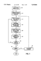
- FIG. 1 is a flowchart illustrating the general operations of the instant invention
- FIG. 2 is a block diagram of the hardware elements of an embodiment used to carry out the operations of FIG. 1;
- FIG. 3 is an illustration of a portion of the scanline buffers depicted in FIG. 2;
- FIG. 4 is a detailed flowchart illustrating the specific steps associated with the multi-bit signal determining step of FIG. 1;
- FIGS. 5A and 5B respectively, illustrate an example bitmap image segment and a template matching a portion thereof
- FIG. 5C shows an alternate embodiment of the sampling window where a restricted region of an 11 ⁇ 11 square window may be used
- FIG. 6 is a schematic illustration of the operation of the video signal generator of FIG. 2 in accordance with the conversion step of FIG. 1;
- FIGS. 7A-7E are examples of image sections at various stages of processing in accordance with the present invention.
- FIGS. 8A-8D are examples of image sections at various stages of processing in accordance with another aspect of the present invention wherein the right-most portions thereof indicate the effect on the output paper.
- video signal and image signal are intended to describe any form of digital signal used to represent a pixel (picture element) within a bitmap image, be it for display, printing, or transmission thereof.
- FIG. 1, in conjunction with FIG. 2, illustrates the process steps used in carrying out the instant invention.
- a binary image bitmap 50 is identified for resolution enhancement.
- the image is a binary image that may be generated from any of a number of sources, including digitizing a hardcopy document, computer generated documents, etc.
- the input document will be characterized hereafter as having a first resolution.
- a portion of the input document is stored in a memory comprising a series of scanline buffers 52, step 22.
- This step is equivalent to "windowing" or selecting a portion of the input image data for examination, where a series of successive scanlines of data, or possibly partial scanlines, are copied or moved to scanline buffers.
- a target pixel at or near the center of the stored region is selected for processing, step 24.
- ASIC application specific integrated circuit
- ASIC 54 uses template matching techniques described hereafter to analyze the binary state of the target and neighboring pixels within the scanline buffers to determine the multi-bit signal.
- the multi-bit signal is converted to at least one resolution enhanced signal at step 28 via the operation of video signal generator 56.
- the resolution enhanced pixel signals produced by the video signal generator may be a multiple-bit or gray-scale output signal, or alternatively a plurality of binary output signals.
- the enhanced pixel signals are passed to an exposure device 58, such as a digital printer, suitable for receiving, and/or temporarily storing the enhanced pixel signals for subsequent output thereof, step 30.
- an exposure device 58 such as a digital printer
- one such device could be the pulse-width position modulated (PWPM) exposure device described in U.S. application Ser. No. 08/118,858 by Cianciosi et al. for "Apparatus for Enhancing Pixel Addressability in a Pulse Width and Position Modulated System,", filed Sep. 8, 1993, the teachings thereof being hereby incorporated by reference.
- PWPM pulse-width position modulated
- the present invention may be incorporated within a multi-color or highlight color printing system to improve the rendition of output images produced thereon.
- an arbitration circuit such as disclosed by Cianciosi et al. in U.S. application Ser. No. 08/118,923 for "Method and Apparatus for Enhancing Discharged Area Developed Regions in a Tri-level Printing System", filed Sep. 8, 1993, may be employed to select from the enhanced resolution black or highlight color output pixels.
- steps 34, 36, and 38 the process repeats for each pixel within a scanline and for each scanline within the input image, given an allowance for a lack of image context around the edges of the image, so as to process the entire image in the same manner.
- FIG. 3 which illustrates one embodiment of the scanline buffers
- the illustrated embodiment utilizes a series of nine scanlines (N -4 , . . . , N, . . . , N 4 ), each capable of storing at least nine pixels (P -4 , . . . , P, . . . , P 4 ) therein.
- a central target pixel X indicated by reference numeral 66 is selected from the center of "window" 68.
- the binary states of target pixel X, and one or more additional pixels within window 68, are then compared to a plurality of equally sized templates, an example of which is illustrated in FIG. 5B.
- FIG. 4 which further illustrates the steps included within determining step 26, the binary states of the individual pixels within window 68 are determined, step 80, and subsequently compared to the pixel states required by one of the templates implemented via ASIC 54.
- FIGS. 5A and 5B An example of such a comparison is shown in FIGS. 5A and 5B.
- FIG. 5A illustrates a portion of a binary image 102, having both black and white pixels therein, and a 9 pixel by 9 scanline window 68 superimposed thereon.
- window 68 is intended to represent a portion of image 102 as would be stored in scanline buffers 52 as previously described.
- FIG. 5B illustrates the detail of a template 104 that would be identified as a match when compared against the binary image signals within window 68. More specifically, as shown in FIG.
- the template contains pixel positions requiring a black pixel for a match (B), pixel positions requiring a white pixel for a match (W), and pixel positions where either black or white may be present for a match (blank).
- a restricted 11 ⁇ 11 template may be used in place of the 9 ⁇ 9 square template.
- the outline for such a template is illustrated in FIG. 5C, where it can be seen that the alternative shape employs the same number of elements as the 9 ⁇ 9 template of FIG. 5B while providing for improved smoothing of features parallel and perpendicular to the scanning laser beam, i.e., for nearly horizontal or nearly vertical features.
- step 84 of FIG. 4 would indicate an affirmative response upon such a comparison and would generate a multi-bit signal representing the intended value or gray-scale image density of target pixel X, step 88. If no match were found after comparison at step 82, a multi-bit value indicative of an all white or all black pixel to be imaged is assigned to the central pixel, and the determination process would continue at step 86 where another template would be selected for comparison against the binary signals within the scanline buffers.
- the ASIC implementation of the template comparison step allows the concurrent comparison of the binary pixel states within the scanline buffers to the identified templates, the output of which is the multi-bit signal representing an enhanced value for the target pixel.
- the operation of ASIC 54 may be optimized so as to improve the processing speed thereof.
- commonality between various templates may be exploited to more efficiently group the templates for processing, thereby resulting in a reduced size ASIC as well as improved speed.
- the template set needed to identify half-bitted and/or jaggy regions within a binary bitmap image may be generated using the process described by Eschbach in U.S. application Ser. No. 08/169,483, "Automated Template Design for Print Enhancement” or by Loce et al. in U.S. application Ser. No. 08/169,565, "Method for Statistical Generation of Density Preserving Templates for Print Enhancement," both of which have been previously incorporated herein by reference for their teachings. More specifically, using the template design process, a series of input documents having half-bitted and jaggy regions therein would be included in the set of training documents so as to cause the generation of templates for the recognition of such regions.
- the template set designed will be symmetric with respect to short- and long-edge printing devices; meaning that the template set is preferably designed to recognize similar patterns in the input bitmap image regardless of whether the image is to be rendered in a short- or long-edge oriented output process.
- the template window 68 is preferably a symmetric window, whether it is the square illustrated in FIG. 3, or the modified window represented in FIG. 5C.
- a multi-bit or enhanced signal may be output by a printing or display device suitable for printing gray-scale images.
- the enhanced pixel is converted into a plurality of pixels having a higher spatial resolution than the input binary image.
- multi-bit image signal 110 is passed to look-up table (LUT) 112, where one of a set of higher spatial resolution pixel combinations may be generated (114a-114p), depending upon the pixel value output by the LUT.
- LUT 112 may be software downloadable to enable customization of the enhancement process.
- FIGS. 7A through 7E are provided.
- the left-most representation is intended to illustrate a portion of a binary image bitmap, specifically the black pixels therein (shown with cross-hatching).
- the middle representation of each figure set shows the various multi-bit, enhanced signal levels assigned to the individual pixels as a result of processing the binary input image in accordance with the present invention.
- the enhanced image signals would be converted to one of the binary pixel sets illustrated in FIG. 6; as represented by the right-most bitmaps which are depicted as having a spatial resolution twice that of the left-most input bitmaps.
- FIGS. 8A through 8D are provided to further illustrate the process for a multi-bit per pixel or gray scale embodiment.
- the left-most representation is again intended to illustrate a portion of a binary image bitmap, where the black pixels are shown as cross-hatched.
- the middle representation of each figure set shows the various multi-bit, enhanced signal levels assigned to the individual pixels as a result of processing the binary input image in accordance with the present invention.
- the right-most representations in FIGS. 8A through 8D depict representative gray-scale or multi-bit output as it would appear on the output medium at the same spatial resolution as the binary image bitmap.
- variable exposure in response to the multi-bit enhanced output may be achieved by various methods, including: pulse-width modulation; amplitude modulation; or a combination of pulse-width and amplitude modulation.
- the output signal used to drive pulse-width or amplitude modulated output devices may be generated by various methods, and could include the use of a look-up table to further reduce range of the multi-bit output to a range matching that of the specific output device employed in a fashion similar to that illustrated in FIG. 6 for the binary output situation.
- the present invention is a method and apparatus for identifying regions within a first binary image where image patterns, often in the form of half-bitting, may be present, converting at least those regions to a multiple-bit per pixel representation so as to accurately represent the image density desired for the region, and further generating an enhanced resolution representation of the region in a second binary image, wherein the second binary image has a spatial resolution greater than the first image, so as to enable an improved rendering of the first binary image.
- the multiple-bit per pixel representation may be used to drive the output of a pulse-width or amplitude modulated marking device.
Abstract
Description
Claims (17)
Priority Applications (2)
| Application Number | Priority Date | Filing Date | Title |
|---|---|---|---|
| US08/241,431 US5539866A (en) | 1994-05-11 | 1994-05-11 | Method and apparatus for accurately rendering half-bitted image pixels |
| JP10861895A JP3810826B2 (en) | 1994-05-11 | 1995-05-02 | Half-bit pixel rendering method and half-bit pixel rendering apparatus |
Applications Claiming Priority (1)
| Application Number | Priority Date | Filing Date | Title |
|---|---|---|---|
| US08/241,431 US5539866A (en) | 1994-05-11 | 1994-05-11 | Method and apparatus for accurately rendering half-bitted image pixels |
Publications (1)
| Publication Number | Publication Date |
|---|---|
| US5539866A true US5539866A (en) | 1996-07-23 |
Family
ID=22910677
Family Applications (1)
| Application Number | Title | Priority Date | Filing Date |
|---|---|---|---|
| US08/241,431 Expired - Lifetime US5539866A (en) | 1994-05-11 | 1994-05-11 | Method and apparatus for accurately rendering half-bitted image pixels |
Country Status (2)
| Country | Link |
|---|---|
| US (1) | US5539866A (en) |
| JP (1) | JP3810826B2 (en) |
Cited By (14)
| Publication number | Priority date | Publication date | Assignee | Title |
|---|---|---|---|---|
| US5689343A (en) * | 1995-05-26 | 1997-11-18 | Xerox Corporation | Area mapping employing reference clusters for high quality noninteger resolution conversion with enhancement |
| US5995679A (en) * | 1995-05-22 | 1999-11-30 | Siemens Aktiengesellschaft | Process for coding image sequences in a transmitter unit |
| US6058248A (en) * | 1997-04-21 | 2000-05-02 | Hewlett-Packard Company | Computerized method for improving data resolution |
| US6181438B1 (en) * | 1997-05-05 | 2001-01-30 | Xerox Corporation | Method and apparatus for digital image darkness control using quantized fractional pixels |
| US6181835B1 (en) | 1997-12-26 | 2001-01-30 | International Business Machines Corporation | Non-integer scaling of raster images with image quality enhancement using an anamorphically scaled intermediate bitmap |
| US6289136B1 (en) * | 1995-03-22 | 2001-09-11 | Canon Kabushiki Kaisha | Image processing method and apparatus |
| US6295078B1 (en) | 1999-05-26 | 2001-09-25 | Hewlett-Packard Company | Methods of providing lower resolution format data into a higher resolution format |
| EP1328112A2 (en) * | 2002-01-14 | 2003-07-16 | Seiko Epson Corporation | Fast text/graphics resolution improvement with chain-code table look-up |
| US20030179954A1 (en) * | 2002-03-25 | 2003-09-25 | Ching-Wei Chang | Optimizing the advantages of multi-level rendering |
| US6678426B1 (en) | 1997-05-13 | 2004-01-13 | Hewlett-Packard Development Company, L.P. | Programmable mapping of lower resolution digital data to a higher resolution for output on a lower resolution device |
| US6753914B1 (en) | 1999-05-26 | 2004-06-22 | Lockheed Martin Corporation | Image correction arrangement |
| US6834124B1 (en) | 2000-10-16 | 2004-12-21 | Xerox Corporation | Adaptive image enhancement filter |
| US20050135694A1 (en) * | 2003-12-19 | 2005-06-23 | Daly Scott J. | Enhancing the quality of decoded quantized images |
| CN1818803B (en) * | 2005-02-02 | 2010-06-16 | 普驰有限责任公司 | Method and system for image print |
Citations (18)
| Publication number | Priority date | Publication date | Assignee | Title |
|---|---|---|---|---|
| US4437122A (en) * | 1981-09-12 | 1984-03-13 | Xerox Corporation | Low resolution raster images |
| US4544922A (en) * | 1981-10-29 | 1985-10-01 | Sony Corporation | Smoothing circuit for display apparatus |
| US4544264A (en) * | 1984-05-17 | 1985-10-01 | International Business Machines Corporation | Fine line print enhancement |
| US4625222A (en) * | 1984-05-17 | 1986-11-25 | International Business Machines Corporation | Interacting print enhancement techniques |
| US4841375A (en) * | 1986-05-29 | 1989-06-20 | Kabushiki Kaisha Toshiba | Image-resolution conversion apparatus for converting a pixel-density of image data |
| US4847641A (en) * | 1988-08-16 | 1989-07-11 | Hewlett-Packard Company | Piece-wise print image enhancement for dot matrix printers |
| US4933689A (en) * | 1989-10-25 | 1990-06-12 | Hewlett-Packard Company | Method and apparatus for print image enhancement |
| US4974171A (en) * | 1989-08-03 | 1990-11-27 | Eastman Kodak Company | Page buffer system for an electronic gray-scale color printer |
| US5125072A (en) * | 1989-07-31 | 1992-06-23 | Eastman Kodak Company | Efficient data storage system for gray-scale printers |
| US5150311A (en) * | 1988-05-17 | 1992-09-22 | Quantel Limited | Electronic print-dot generation |
| US5155478A (en) * | 1988-04-22 | 1992-10-13 | International Business Machines Corporation | Method and apparatus for converting gray scale |
| US5161035A (en) * | 1989-10-31 | 1992-11-03 | Brother Kogyo Kabushiki Kaisha | Digital image processing device for enlarging original image with high fidelity |
| US5161213A (en) * | 1988-05-27 | 1992-11-03 | Wang Laboratories, Inc. | Method for black and white image reduction based upon averaging black/white pixel counts of neighboring blocks |
| US5191640A (en) * | 1990-12-26 | 1993-03-02 | Xerox Corporation | Method for optimal discrete rendering of images |
| US5193008A (en) * | 1990-11-07 | 1993-03-09 | Dp-Tek, Inc. | Interleaving vertical pixels in raster-based laser printers |
| US5216753A (en) * | 1990-03-29 | 1993-06-01 | Eastman Kodak Company | Halftone compression with sharpness preservation |
| US5271095A (en) * | 1988-12-20 | 1993-12-14 | Kabushiki Kaisha Toshiba | Image processing apparatus for estimating halftone images from bilevel and pseudo halftone images |
| US5276787A (en) * | 1989-04-17 | 1994-01-04 | Quantel Limited | Electronic graphic system |
-
1994
- 1994-05-11 US US08/241,431 patent/US5539866A/en not_active Expired - Lifetime
-
1995
- 1995-05-02 JP JP10861895A patent/JP3810826B2/en not_active Expired - Fee Related
Patent Citations (19)
| Publication number | Priority date | Publication date | Assignee | Title |
|---|---|---|---|---|
| US4437122B1 (en) * | 1981-09-12 | 1993-03-30 | Xerox Corp | |
| US4437122A (en) * | 1981-09-12 | 1984-03-13 | Xerox Corporation | Low resolution raster images |
| US4544922A (en) * | 1981-10-29 | 1985-10-01 | Sony Corporation | Smoothing circuit for display apparatus |
| US4544264A (en) * | 1984-05-17 | 1985-10-01 | International Business Machines Corporation | Fine line print enhancement |
| US4625222A (en) * | 1984-05-17 | 1986-11-25 | International Business Machines Corporation | Interacting print enhancement techniques |
| US4841375A (en) * | 1986-05-29 | 1989-06-20 | Kabushiki Kaisha Toshiba | Image-resolution conversion apparatus for converting a pixel-density of image data |
| US5155478A (en) * | 1988-04-22 | 1992-10-13 | International Business Machines Corporation | Method and apparatus for converting gray scale |
| US5150311A (en) * | 1988-05-17 | 1992-09-22 | Quantel Limited | Electronic print-dot generation |
| US5161213A (en) * | 1988-05-27 | 1992-11-03 | Wang Laboratories, Inc. | Method for black and white image reduction based upon averaging black/white pixel counts of neighboring blocks |
| US4847641A (en) * | 1988-08-16 | 1989-07-11 | Hewlett-Packard Company | Piece-wise print image enhancement for dot matrix printers |
| US5271095A (en) * | 1988-12-20 | 1993-12-14 | Kabushiki Kaisha Toshiba | Image processing apparatus for estimating halftone images from bilevel and pseudo halftone images |
| US5276787A (en) * | 1989-04-17 | 1994-01-04 | Quantel Limited | Electronic graphic system |
| US5125072A (en) * | 1989-07-31 | 1992-06-23 | Eastman Kodak Company | Efficient data storage system for gray-scale printers |
| US4974171A (en) * | 1989-08-03 | 1990-11-27 | Eastman Kodak Company | Page buffer system for an electronic gray-scale color printer |
| US4933689A (en) * | 1989-10-25 | 1990-06-12 | Hewlett-Packard Company | Method and apparatus for print image enhancement |
| US5161035A (en) * | 1989-10-31 | 1992-11-03 | Brother Kogyo Kabushiki Kaisha | Digital image processing device for enlarging original image with high fidelity |
| US5216753A (en) * | 1990-03-29 | 1993-06-01 | Eastman Kodak Company | Halftone compression with sharpness preservation |
| US5193008A (en) * | 1990-11-07 | 1993-03-09 | Dp-Tek, Inc. | Interleaving vertical pixels in raster-based laser printers |
| US5191640A (en) * | 1990-12-26 | 1993-03-02 | Xerox Corporation | Method for optimal discrete rendering of images |
Non-Patent Citations (6)
| Title |
|---|
| Edward R. Dougherty et al., Optimal mean absolute error hit or miss filters: morphological representation and estimation of the binary conditional expectation , Optical Engineering, vol. 32, No. 4, Apr. 1993, pp. 815 827. * |
| Edward R. Dougherty et al., Optimal mean-absolute-error hit-or-miss filters: morphological representation and estimation of the binary conditional expectation, Optical Engineering, vol. 32, No. 4, Apr. 1993, pp. 815-827. |
| Mathematical Morphology in Image Processing , pp. 43 90 (Edward R. Dougherty ed., Marcel Dekker 1992). * |
| Mathematical Morphology in Image Processing, pp. 43-90 (Edward R. Dougherty ed., Marcel Dekker 1992). |
| Robert P. Loce et al., Optimal Morphological Restoration: The Morphological Filter Mean Absolute Error Theorem , Journal of Visual Communications and Image Representation, (Academic Press), vol. 3, No. 4, Dec. 1992, pp. 412 432. * |
| Robert P. Loce et al., Optimal Morphological Restoration: The Morphological Filter Mean-Absolute-Error Theorem, Journal of Visual Communications and Image Representation, (Academic Press), vol. 3, No. 4, Dec. 1992, pp. 412-432. |
Cited By (23)
| Publication number | Priority date | Publication date | Assignee | Title |
|---|---|---|---|---|
| US6289136B1 (en) * | 1995-03-22 | 2001-09-11 | Canon Kabushiki Kaisha | Image processing method and apparatus |
| US5995679A (en) * | 1995-05-22 | 1999-11-30 | Siemens Aktiengesellschaft | Process for coding image sequences in a transmitter unit |
| US5689343A (en) * | 1995-05-26 | 1997-11-18 | Xerox Corporation | Area mapping employing reference clusters for high quality noninteger resolution conversion with enhancement |
| US6466702B1 (en) | 1997-04-21 | 2002-10-15 | Hewlett-Packard Company | Apparatus and method of building an electronic database for resolution synthesis |
| US6058248A (en) * | 1997-04-21 | 2000-05-02 | Hewlett-Packard Company | Computerized method for improving data resolution |
| US6075926A (en) * | 1997-04-21 | 2000-06-13 | Hewlett-Packard Company | Computerized method for improving data resolution |
| US6181438B1 (en) * | 1997-05-05 | 2001-01-30 | Xerox Corporation | Method and apparatus for digital image darkness control using quantized fractional pixels |
| US6678426B1 (en) | 1997-05-13 | 2004-01-13 | Hewlett-Packard Development Company, L.P. | Programmable mapping of lower resolution digital data to a higher resolution for output on a lower resolution device |
| US6181835B1 (en) | 1997-12-26 | 2001-01-30 | International Business Machines Corporation | Non-integer scaling of raster images with image quality enhancement using an anamorphically scaled intermediate bitmap |
| US6295078B1 (en) | 1999-05-26 | 2001-09-25 | Hewlett-Packard Company | Methods of providing lower resolution format data into a higher resolution format |
| US6344870B1 (en) | 1999-05-26 | 2002-02-05 | Hewlett-Packard Company | Methods of providing lower resolution format data into higher resolution format |
| US6445404B1 (en) | 1999-05-26 | 2002-09-03 | Hewlett-Packard Company | Methods of providing lower resolution format data into a higher resolution format |
| US6753914B1 (en) | 1999-05-26 | 2004-06-22 | Lockheed Martin Corporation | Image correction arrangement |
| US6834124B1 (en) | 2000-10-16 | 2004-12-21 | Xerox Corporation | Adaptive image enhancement filter |
| US20030132943A1 (en) * | 2002-01-14 | 2003-07-17 | Guleryuz Onur G. | Fast text/graphics resolution improvement with chain-code table look-up |
| EP1328112A3 (en) * | 2002-01-14 | 2004-11-03 | Seiko Epson Corporation | Fast text/graphics resolution improvement with chain-code table look-up |
| EP1328112A2 (en) * | 2002-01-14 | 2003-07-16 | Seiko Epson Corporation | Fast text/graphics resolution improvement with chain-code table look-up |
| US6927780B2 (en) | 2002-01-14 | 2005-08-09 | Seiko Epson Corporation | Fast text/graphics resolution improvement with chain-code table look-up |
| US20030179954A1 (en) * | 2002-03-25 | 2003-09-25 | Ching-Wei Chang | Optimizing the advantages of multi-level rendering |
| US7046863B2 (en) * | 2002-03-25 | 2006-05-16 | Sharp Laboratories Of America, Inc. | Optimizing the advantages of multi-level rendering |
| US20050135694A1 (en) * | 2003-12-19 | 2005-06-23 | Daly Scott J. | Enhancing the quality of decoded quantized images |
| US7440633B2 (en) * | 2003-12-19 | 2008-10-21 | Sharp Laboratories Of America, Inc. | Enhancing the quality of decoded quantized images |
| CN1818803B (en) * | 2005-02-02 | 2010-06-16 | 普驰有限责任公司 | Method and system for image print |
Also Published As
| Publication number | Publication date |
|---|---|
| JPH07322057A (en) | 1995-12-08 |
| JP3810826B2 (en) | 2006-08-16 |
Similar Documents
| Publication | Publication Date | Title |
|---|---|---|
| US5387985A (en) | Non-integer image resolution conversion using statistically generated look-up tables | |
| US5696845A (en) | Method for design and implementation of an image resolution enhancement system that employs statistically generated look-up tables | |
| US5742703A (en) | Method and apparatus for the resolution enhancement of gray-scale images that include text and line art | |
| US5737455A (en) | Antialiasing with grey masking techniques | |
| US6686922B2 (en) | Adaptive thresholding using loose gray scale template matching | |
| EP0571167B1 (en) | High addressability image generator using pseudo interpolation of video and screen data | |
| JP4262112B2 (en) | Laser printer that generates high-quality image data for printing | |
| US6157736A (en) | Method and apparatus for automatic image segmentation using template matching filters | |
| EP0814431B1 (en) | Subpixel character positioning with antialiasing with grey masking techniques | |
| US6757431B2 (en) | Resolution conversion for anti-aliased images using loose gray scale template matching | |
| CA2132248C (en) | Apparatus and method for arbitrary binary resolution conversion | |
| US5666470A (en) | Method and apparatus for appearance tuning of bitmap images | |
| US5359423A (en) | Method for statistical generation of density preserving templates for print enhancement | |
| JP4471062B2 (en) | Adaptive image enhancement filter and method of generating enhanced image data | |
| US5539866A (en) | Method and apparatus for accurately rendering half-bitted image pixels | |
| JP3176195B2 (en) | Image processing device | |
| EP0708415B1 (en) | Four-quadrant scaling of dot matrix data | |
| US5862305A (en) | Logic filters for resolution conversion of digital images | |
| JPH11154226A (en) | Method and device for improving resolution | |
| US5758034A (en) | Video path architecture including logic filters for resolution conversion of digital images | |
| US5812742A (en) | Apparatus and method for processing two-tone image data so as to smooth image and convert each image pixel into a plurality of pixels | |
| US6480302B1 (en) | Image processing apparatus and image processing method | |
| EP0696131A2 (en) | A method and system for processing image information using screening and error diffusion | |
| JP3092769B2 (en) | Image processing device | |
| JP4050382B2 (en) | Multi-value image smoothing apparatus and image forming apparatus |
Legal Events
| Date | Code | Title | Description |
|---|---|---|---|
| AS | Assignment |
Owner name: XEROX CORPORATION, CONNECTICUT Free format text: ASSIGNMENT OF ASSIGNORS INTEREST;ASSIGNORS:BANTON, MARTIN E.;CHARISSIS, DONNA M.;REEL/FRAME:007079/0807 Effective date: 19940617 |
|
| STCF | Information on status: patent grant |
Free format text: PATENTED CASE |
|
| FPAY | Fee payment |
Year of fee payment: 4 |
|
| AS | Assignment |
Owner name: BANK ONE, NA, AS ADMINISTRATIVE AGENT, ILLINOIS Free format text: SECURITY INTEREST;ASSIGNOR:XEROX CORPORATION;REEL/FRAME:013153/0001 Effective date: 20020621 |
|
| AS | Assignment |
Owner name: JPMORGAN CHASE BANK, AS COLLATERAL AGENT, TEXAS Free format text: SECURITY AGREEMENT;ASSIGNOR:XEROX CORPORATION;REEL/FRAME:015134/0476 Effective date: 20030625 Owner name: JPMORGAN CHASE BANK, AS COLLATERAL AGENT,TEXAS Free format text: SECURITY AGREEMENT;ASSIGNOR:XEROX CORPORATION;REEL/FRAME:015134/0476 Effective date: 20030625 |
|
| FPAY | Fee payment |
Year of fee payment: 8 |
|
| FPAY | Fee payment |
Year of fee payment: 12 |
|
| AS | Assignment |
Owner name: XEROX CORPORATION, CONNECTICUT Free format text: RELEASE BY SECURED PARTY;ASSIGNOR:JPMORGAN CHASE BANK, N.A. AS SUCCESSOR-IN-INTEREST ADMINISTRATIVE AGENT AND COLLATERAL AGENT TO JPMORGAN CHASE BANK;REEL/FRAME:066728/0193 Effective date: 20220822 |