US5549109A - Sheathed multipolar catheter and multipolar guidewire for sensing cardiac electrical activity - Google Patents
Sheathed multipolar catheter and multipolar guidewire for sensing cardiac electrical activity Download PDFInfo
- Publication number
- US5549109A US5549109A US08/353,529 US35352994A US5549109A US 5549109 A US5549109 A US 5549109A US 35352994 A US35352994 A US 35352994A US 5549109 A US5549109 A US 5549109A
- Authority
- US
- United States
- Prior art keywords
- guidewire
- catheter
- distal
- proximal
- insulated electrical
- Prior art date
- Legal status (The legal status is an assumption and is not a legal conclusion. Google has not performed a legal analysis and makes no representation as to the accuracy of the status listed.)
- Expired - Lifetime
Links
Images


Classifications
-
- A—HUMAN NECESSITIES
- A61—MEDICAL OR VETERINARY SCIENCE; HYGIENE
- A61B—DIAGNOSIS; SURGERY; IDENTIFICATION
- A61B5/00—Measuring for diagnostic purposes; Identification of persons
- A61B5/68—Arrangements of detecting, measuring or recording means, e.g. sensors, in relation to patient
- A61B5/6846—Arrangements of detecting, measuring or recording means, e.g. sensors, in relation to patient specially adapted to be brought in contact with an internal body part, i.e. invasive
- A61B5/6847—Arrangements of detecting, measuring or recording means, e.g. sensors, in relation to patient specially adapted to be brought in contact with an internal body part, i.e. invasive mounted on an invasive device
- A61B5/6851—Guide wires
-
- A—HUMAN NECESSITIES
- A61—MEDICAL OR VETERINARY SCIENCE; HYGIENE
- A61B—DIAGNOSIS; SURGERY; IDENTIFICATION
- A61B5/00—Measuring for diagnostic purposes; Identification of persons
- A61B5/24—Detecting, measuring or recording bioelectric or biomagnetic signals of the body or parts thereof
- A61B5/25—Bioelectric electrodes therefor
- A61B5/279—Bioelectric electrodes therefor specially adapted for particular uses
- A61B5/28—Bioelectric electrodes therefor specially adapted for particular uses for electrocardiography [ECG]
- A61B5/283—Invasive
- A61B5/287—Holders for multiple electrodes, e.g. electrode catheters for electrophysiological study [EPS]
Definitions
- This invention is a medical device. It is a multipolar catheter assembly optionally in combination with a guidewire.
- Each of the catheter and the guidewire may be sheathed, especially with a fluoropolymeric composition comprising tetrafluoroethylene, hexafluoropropylene, and vinylidene fluoride, and have multiple electrodes at their distal ends.
- the catheter and the guidewire may be used at virtually any point within the vasculature particularly, however, within the cardiac arteries or veins, perhaps in conjunction with external electrocardiogram leads, to map the body's electrical activity. When used in the heart, they may be used to determine the source of a cardiac arrythmia. The intimate presence of the guidewire or catheter body in the cardiac vasculature allows the response time to changes in cardiac electrical activity is very quick.
- the invention is also a method for mapping the electrical activity of the heart by use of one or more of these inventive guidewires or catheters in the cardiac arteries or veins. They may also be used to determine the local electrical activity of any site within the body, such as in the brain.
- the heartbeat is caused by the rhythmic and orderly contraction of heart chambers surrounded by heart muscles.
- the normal heartbeat starts with the contraction of the atria (atrial systole) followed by contraction of the ventricles (ventricular systole) while the atria are in atrial diastole. During the following diastole, all four chambers are sequentially relaxed.
- the heartbeat originates in a cardiac conduction system made up of the sinoatrial node (SA node), the internodal atrial pathways, the atrioventricular node (AV node), the Bundle of His and its various branches, and the Purkinje system.
- the Bundle of His conduction system spreads the heartbeat to the apex of the myocardium.
- the SA node typically discharges more quickly than the other portions of the system. Acting as a natural cardiac pacemaker, the SA node discharge rate generally determines the rate at which the heart beats.
- the impulses generated in the SA node pass through the atrial pathways to the AV node, to the Bundle of His and thence to its branches and the ventricular muscle through the Purkinje system.
- the various parts of the conduction system and the myocardium itself are capable of spontaneous discharge.
- the various portions of the conduction system are mostly striate, modified cardiac muscle having less than distinct boundaries.
- the human heart rate is about 70 beats per second at rest. That rate is accelerated (tachycardia) by exercise, fever, and the like; the rate is slowed (brachycardia) during sleep. Other normal physical causes, e.g., breathing, cause a variation in heart rate.
- arrythmia such as paroxysmal ventricular tachycardia are often benign, they are sometimes associated with ventricular fibrillation. Ventricular fibrillation, in which the ventricular muscle fibers contract irregularly, cause the heart to pump blood very inefficiently. The resultant serious decline in cardiac output, if untreated, is often fatal.
- Control of arrhythmia is undertaken in a variety of ways.
- Antiarrhythmic drugs often slow conduction in the conduction system and the myocardium. Some block Na + , Ca ++ channels or ⁇ -adrenergic activity in the heart. These treatments are effective in clinical situations but often must be continued for extended periods of time.
- Another method for controlling arrhythmia, particularly tachycardia, short of open heart surgery to surgically section the Bundle of His, is via the use of an ablation catheter. These devices are used to ablate cardiac conduction pathways.
- Cohen shows a catheter which is inserted in typical fashion into a chamber of the heart (preferably entering the body remotely through the femoral artery) so that the distal end of the catheter may be positioned against the heart wall in close proximity to one of the cardiac conduction pathways.
- the catheter carries detectors for sensing various electrical potentials within the heart, e.g., the HRA (high right atrium), the HBE (His Bundle electrogram), and the VA (ventricular apex).
- the distal end of the catheter also carries the termination of a laser optical conduit.
- the laser is used to ablate the offending conduction pathway tissue. Lasering of the chosen pathway is carried out until the monitored cardiac activity is properly modified, e.g., when the Bundle of His is ablated, the surgeon notes that the atrial and ventricular activity have become asynchronous.
- U.S. Pat. No. 5,056,517, to Fenici discloses a cardiac electrocatheter optionally containing ablation wires, fiber optics, and distal and proximal electrodes for intracardial mapping.
- mapping of cardiac electrical activity is desirable.
- the mapping of that activity is desirably more and more precise.
- choice of pacemaker type, proper placement of pacemaker leads, and proper programming of pacemaker variables depends in large measure upon the coronary malady to be corrected.
- implantable pacemakers have been provided with an internationally adopted 4 or 5-letter code specifying which of the thousands of combinations of electrical sensing, pacing, inhibiting, etc., activities the specific pacemaker may undertake.
- the pacemaker chosen for a patient with acute inferior myocardial infarction is quite different from that chosen for a patient with acute anterior myocardial infarction and those likely will be quite different from pacemakers chosen for an aberrant physiological reflex such as carotid sinus hypersensitivity.
- the cardiac electrical activity is different; in each case the need to properly assess the activity and then either to inhibit it or to enhance it so to restore cardiac muscle activity to a normal and proper rate is obvious to all who take the time to consider it.
- FIG. 1 is an side view of the inventive multipolar catheter assembly.
- FIG. 2 is an enlarged, cutaway, side view of the distal section of the multipolar catheter assembly.
- FIG. 3 is an enlarged cutaway side view of the inventive multipolar guidewire assembly.
- FIG. 4 is an enlarged side view of the distal section of the guidewire assembly.
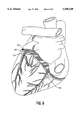
- FIGS. 5 and 6 are anterior and posterior views of a human heart showing the major cardiac arteries and cardiac veins suitable for placement of the inventive guidewires and catheters as used for mapping cardiac activity according to the method of this invention.
- FIGS. 7, 8 and 9 are graphs of cardiac electrical activity made during an the experimental procedure.
- This invention is a catheter, having multiple electrical sensing poles or electrodes in the region of its distal end.
- the catheter may be used in conjunction with a guidewire either with or without multiple electrical sensing poles or electrodes in the region of its distal end.
- Central to this device is the use of a fluoropolymeric mixture or alloy of tetrafluoroethylene, hexafluoropropylene, and vinylidene fluoride as a sheath on the exterior of at least one of the catheter or the guidewire.
- the catheter, in conjunction with that guidewire may be used for mapping coronary electrical activity in either or both of the coronary arteries or in coronary veins.
- the guidewire may be used with a vasoocclusive device, such as a vasoocclusive coil or braid, with or without interior or exterior ancillary fibrous material.
- a vasoocclusive device such as a vasoocclusive coil or braid
- the guidewire may be used to occlude small coronary arteries or veins to remedy a detected arrhythmia even during the process of monitoring cardiac electrical activity.
- the inventive catheter body may be used to infuse diagnostic or therapeutic agents into the cardiac vasculature during use as a mapping tool and even while the guidewire is in place.
- the invention also includes a guidewire which has a braided or flat wound tube made up of individually insulated conductive wires or filaments.
- the conductors are attached individually to sensor points or electrodes, which electrodes are spaced apart from each other.
- the woven braid may be woven about a wire core to provide some additional stiffness to the guidewire assembly.
- the guidewire may be so equipped as to introduce vasoocclusive devices at its distal end.
- an electrical junction, a socket or the like may be installed to allow ready connection to an external monitoring device.
- At least a portion of the guidewire may be ensheathed with a previously, at least partially crosslinked, mixture or alloy of tetrafluoroethylene, hexafluoropropylene, and vinylidene fluoride.
- the fluoropolymer composition is preferably extruded into suitably sized tubing, at least partially cross-linked (often using radiation such as electron beam), placed about the guidewire, and heated to shrink the tubing into intimate contact with the guidewire.
- the catheter is typically a multilayer assembly often having a number of coaxial polymeric tubes, the tubes may be separated by a braided or flat wound tube made up of individually insulated conductive wires or filaments.
- the tube may be made of a combination of conductive wires and other filamentary material, such as Dacron threads, to complete the tube when only a limited number of electrodes are needed.
- the conductors are attached individually to sensor points or electrodes, which electrodes are spaced apart from each other.
- the braided or laid-up tube may be woven or laid-up tube about one or more inner polymeric tubing cores to provide structure to the catheter assembly.
- an electrical junction may be installed to allow ready connection to an external monitoring device.
- the areas of the catheter which do not constitute a sensor area may be covered with a fluoropolymer composition of tetrafluoroethylene, hexafluoropropylene, and vinylidene fluoride. It is preferably placed onto the catheter by first extruding the polymeric composition into suitably sized tubing, at least partially cross-linking the polymer (often using radiation such as electron beam), placing the polymer about the catheter, and heating the polymer to shrink it into intimate contact with the catheter body.
- the guidewire and the catheter may be introduced from an external site such as the femoral artery or vein up through the mid portion of the body into the cardiac arteries or veins. There, the guidewire and the catheter may be placed in such a fashion that the local cardiac electrical activity within the cardiac muscle wall as monitored through the cardiac vein or artery wall may be measured and monitored. By choice of monitoring site throughout the coronary vasculature system, the electrical activity of the heart may be completely mapped.
- the guidewire and catheter may be used during these monitoring activities either in a bipolar mode, that is to say, using adjacent pairs of electrical contacts at their distal tip, or may be used in unipolar mode in conjunction with other electrodes suitably placed exterior or interior to the body or to the heart.
- this invention is a medical device.
- the invention is a catheter, optionally containing a guidewire, suitable for monitoring electrical activity interior to the body.
- the optional guidewire may be a typical guidewire or may have multiple poles or electrodes on its distal end.
- Central to this device is the use of a fluoropolymeric mixture or alloy of tetrafluoroethylene, hexafluoropropylene, and vinylidene fluoride as a sheath on the exterior of at least one of the catheter or the guidewire.
- One important aspect of this invention is the monitoring of cardiac electrical activity by placement of the catheter's (and optionally, the guidewire's) multiple contacts in cardiac veins or in the cardiac arteries. Because of the size and flexibility of this device, it is suitable for monitoring other sources of electrical activity within the human or animal body.
- FIG. 1 shows a side view of a catheter (100) made according to this invention.
- the depiction in the figure is a typical configuration using the concept of sections having multiple flexibility generally as described in U.S. Pat. No. 4,739,768, to Engelson, but is not limited to the specifics of that patent.
- Catheter (100) is made is an elongate tube often between 50 and 300 cm. in length and is made up of the following portions: a sensor section (102), a distal section (104) just proximal of the sensor section (102), a mid section (106), and a proximal section (108).
- the catheter has a lumen extending axially from the most proximal portion of the catheter (100) to the distal end of the sensor section (102).
- a proximal fitting (110) for passage of the guidewire through the catheter lumen and having a sidearm for introduction of fluids into the catheter may also be employed.
- An electrical connector (112) for connection to the electrodes (114) through the wires of the wire tube (116) is also desirable.
- the sensor section (102) is shown on more detail in FIG. 2 but generally is a tube (116) of insulated wire or other filamentary material which has either been woven or flat wound usually over (and consequently is concentric with) a polymeric tube to provide an open lumen in that section.
- the tube may be made up of a sufficient number of wires to allow connection to electrodes (114) of an appropriate number for the task involved. For instance, when mapping the electrical activity in the somewhat short circumflex artery, only a fairly short sensor section (102) with a few electrodes is desirable.
- the catheter (100) in FIG. 1 is equipped with four electrodes (114) for just such a purpose.
- the electrodes (114) may be spaced as appropriate but, for electrodes which are about 0.010 in length, a spacing of 1 mm. to 1 cm. is acceptable. Here, since only a few electrodes are involved, only a few insulated wires would be incorporated into the wire tube (116). The remainder of the filaments to complete the filamentary tube (116) could be Dacron, nylon, silk, or other appropriate natural or synthetic material.
- the number of electrodes may be any number but is at least one. We have found that a practical upper limit of the number of electrodes is sixteen, but that number is set only because of the difficulty of weaving very small insulated wires into a tube which retains sufficient flexibility to traverse the noted vasculature without causing trauma.
- Each electrode (114) preferably is attached to one wire in the wire tube (116) but such is not necessary.
- Wire tube (116) extends from the sensor section (102) along the length of the catheter (100) to the proximal end and its connector (116).
- the outer diameter of the electrodes (114) and the remainder of the sensor section (102) typically is between 0.030 and 0.100 inches but preferably is between 0.030 and 0.050 inches and most preferably is between 0.035 and 0.040 inches.
- the inner diameter of the sensor section (102) is sufficiently large to accommodate the guidewire used in the device but desirably provides about 0.002 to 0.005 inches of clearance between the guidewire and the tubing. For a 0.016 to 0.018 inch diameter guidewire, the inner diameter of the sensor section (102) would therefore be 0.018 to 0.023 inches.
- Distal section (104) Adjacent on the proximal end of the sensor section (102) is distal section (104).
- Distal section (104) is the most flexible of the three section (104), (104), and (106) and typically makes up 5 to 30% of the length of the catheter (100). This flexibility permits the catheter to track along a guidewire with ease into the various curves and loops it encounters in the human vasculature.
- It typically has a sheathing (117) made of a very soft material such as a silicone or a low density polyethylene or other suitable polymer.
- the wall thickness of the soft tubing making up distal section is preferably nominally 0.002".
- sheaths (119) of the polymeric tubing between the electrodes (114) and between the distal end of the distal section (104) and the electrodes.
- the sheathing (117) on the distal section (104) need not be of the same composition as that in the sensor section (102) although it is desirable to do so.
- mid section (106) adjacent on the proximal end of the distal section (104) is mid section (106).
- Mid section (106) is the midway in flexibility between distal section (104) and proximal section (108) and typically makes up 5 to 30% of the length of the catheter (100).
- This section provides greater column strength in the distal regions of the catheter as it is moved along the tortuous path of the vasculature but with greater flexibility than the proximal section (108).
- This segment may be formed by extending the tubing found in the distal section (104) over and coaxial to a stiffer tubing composed of, e.g., polypropylene or high density polyethylene.
- mid section (106) and the proximal section (108) also be at least partially covered with a tubing of a copolymer of tetrafluoroethylene, hexafluoropropylene, and vinylidene fluoride or an alloy or mixture of the three as described above.
- the proximal section (108) is the most stiff of the tubing sections and typically makes up 70 to 95% of the of the total length of the tubular member. Again, the section may be made by extending the tubing found in the distal section (104) and the outer surface of mid section (106) over and coaxial to a stiffer tubing composed of, e.g., polypropylene or high density polyethylene. As with the other sections, the inner diameter of the proximal section (108) should provide about 0.002 to 0.005 inches of clearance between the guidewire and the inner diameter of the tubing. For a 0.016 to 0.018 inch diameter guidewire, the inner diameter of the proximal section (108) would therefore be 0.018 to 0.023 inches. Choice of suitable, stiffer polymers to maintain the outer diameter at a relatively constant value, if such is desired, is within the ambit of one having ordinary skill in this art.
- the catheter (100) have sections of varying stiffness. Such a construction obviously may not entail discrete or quantum changes in the stiffness of the catheter body to occur. Additionally it is desired that the inner and/or outer surfaces of the catheter body be coated with a polymer to increase the lubricity of the catheter either with respect to the guidewire or with the lumen of the vasculature.
- Hydrophilic polymers such as polyvinylpyrrolidone, polyethylene oxide, and various acrylate-based polymers are suitable choices as hydrophilic polymers. Hydrophobic polymers such as polysulfones and polyfluoroalkanes are also suitable.
- a fluoropolymeric composition comprising a copolymer of tetrafluoroethylene, hexafluoropropylene, and vinylidene fluoride or an alloy or mixture of the three.
- a fluoropolymeric composition comprising a copolymer of tetrafluoroethylene, hexafluoropropylene, and vinylidene fluoride or an alloy or mixture of the three.
- THV Fluoroplastics produced by 3M, particularly THV 200, THV 300, THV 400, and THV 500.
- Preferred compositions include those which have a melting range between about 115° and 180° C.
- the polymeric composition is preferably placed onto the catheter by first extruding the polymeric composition into suitably sized tubing, at least partially cross-linking the polymer (often using radiation such as electron beam), placing the polymer about the catheter, and heating the polymer to shrink it onto the catheter body.
- extrusion of the composition is desirably accomplished using commercially available extruder equipment having, e.g., a 24:1 single screw head which has set up for tubing extrusion.
- the tubing should be extruded with a wall thickness which ultimately (or as-installed on the catheter) is between about 0.0015 in. to 0.0035 in. with an inner diameter matching the outer diameter of the catheter section to be sheathed.
- Extruder head temperatures for the preferred materials are preferably in the region of 370°-540° F.
- the tubing after extrusion, is then irradiated by passing the tubing through an irradiation zone containing an electron beam (or other suitable radiation source) of about 15 to 40 MRads and then expanding the tubing, e.g., inflating with it air while heating the tubing.
- This expansion provides the tubing with biaxial elongation (both circumferential and lengthwise) and renders the tubing heat shrinkable.
- the expansion should be sufficient to produce a tubing which desirably is shrinkable by a factor of up to about 2.5 when shrunk onto the catheter body to form the sheathing.
- the catheter (100) may be terminated with a proximal attachment (110) having a syringe sidearm and an electrical connector (112) for the electrodes (114).
- the wire tube (116) is generally made up of insulated conductors, each of which individually extends from the distal portion of the catheter assembly (100) to its proximal end. Each wire is insulated along its length but is stripped for contact and electrical joining with an electrical junction (112) at the proximal end of the catheter and for contact with an electrode (114) in the sensor section (102) of the catheter, by known techniques such as soldering, brazing, or welding.
- the tube of conductors preferably is woven, that is to say, that the conductors assume an in-and-out relationship with each other much in the same way that cloth is woven and pass in a spiral from the distal end of the tube to the proximal end of the tube.
- This weave may be regular, having each conductive filament trade inside for outside positions at every junction with a crossing conductor.
- the conductors may be grouped together in bundles or ribbons for multiple weaving.
- the weave may be the same configuration from distal to proximal end or it may be changed as desired from one end to the other to allow changes of flexibility or changes in overall diameter.
- the optional sheathing (119) is shown in the spaces between the electrodes (114) and in the gap between the distal section sheathing (117) and the most proximal electrode.
- the conductors be interwoven to form the regularly woven tube around the inner polymeric tubing (118), it is also within the purview of this invention that multiple conductors be merely twisted or flat-wound around the inner polymeric tubing (118) to form the tube of conductors. That is to say, an inner number of wires would be laid diagonally to the longitudinal axis of the inner polymeric tubing (118) and flat-wound spirally one way, e.g., clockwise or counterclockwise, around the tubing. An outer collection of conductor wires would be laid diagonally to the axis of the inner polymeric tubing (118) and flat-wound spirally or twisted in the opposite direction around the tubing and the inner layer of conductors.
- conductive materials may be used as the conductive wires in this invention, e.g., metals such as silver, gold, platinum and copper, such materials are well known and a choice is well within skill of the designer in this art.
- conductive materials e.g., metals such as silver, gold, platinum and copper
- typical electrical grade copper wires of a suitable diameter e.g., 0.004 to 0.010 inches in diameter, is excellent and provides the necessary strength and flexibility for cardiac service.
- wires are also within the scope of one having ordinary skill in this art.
- polyimide resins may be applied to the wires in a layer thin enough that the overall size of the resulting guidewire assembly is not excessive, the crosstalk between adjacent wires is very low, and the biocompatibility of the polymer is widely accepted.
- Polyethylene, polypropylene, polybutene, polyurethane, and mixtures and copolymers of these polymers are also quite suitable.
- the minimum number of conductors in the wire tube is one.
- the remainder of the wires may be other filamentary material such as Dacron, silk, nylon, or other suitable material.
- Use of non-conductors retains the presence of the tube as a structural feature but minimizes the number of stiff wires in the tube if only a limited number of electrodes is needed in the sensor section.
- the number of wires either woven into the tube or placed in the flat-wound variations may be as many as is desirable for the specific task involved as constrained by the necessary flexibility of the catheter. For instance, we have found that for 41 gauge copper wires (0.0066 inches in diameter) having a thin polyimide insulator coating, that tubes may be woven having 0.018 inch outside diameters with 16 independently monitorable electrodes at the distal tip. Obviously, with additional wires or using bundles of wires, the catheter assembly will be thicker and potentially less flexible. Nevertheless, it is within the scope of this invention that any reasonable number of woven or flat wound wires be utilized.
- FIG. 3 shows a partial cutaway side view of the inventive guidewire assembly (300).
- the guidewire itself is fairly flexible and is torqueable and often has an overall length between about 70 and about 300 cm between its proximal end and its distal end.
- the typical maximum outer diameter is often between 0.006 and 0.060, preferably between 0.010 and 0.040 inches.
- the diameter of the guidewire assembly may be constant along its length, more typically the diameter will range from a minimum of 0.015 to 0.020 inches at its distal end to 0.020 to 0.035 at its proximal.
- the guidewire is generally made up of a woven tube (302) comprising insulated conductors, each of which individually extends from the distal portion of the guidewire assembly to the proximal end of the guidewire assembly.
- Each wire or filament is insulated along its length but is stripped for contact and electrical joining with an electrical junction (304) at the proximal end of the guidewire assembly and for contact with an electrode (306) at the distal end of the guidewire assembly.
- the tube of conductors preferably is woven, that is to say, that the conductors assume an in-and-out relationship with each other much in the same way that cloth is woven and pass in a spiral from one end of the guidewire assembly to the other.
- This weave may be regular, having each conductive filament trade inside for outside positions at every junction with a crossing conductor.
- the conductors may be grouped together in bundles or ribbons for multiple weaving.
- the weave may be the same configuration from distal to proximal end or it may be changed as desired from one end to the other to allow changes of flexibility or changes in overall diameter.
- the conductors be interwoven to form the regularly woven tube
- multiple conductors be merely twisted or wound around the core to form the tube of conductors. That is to say, an inner number of wires would be laid diagonally to the axis of the core and flat-wound spirally one way, e.g., clockwise or counterclockwise, around the core and the outer collection of conductor wires would be laid diagonally to the axis of the guidewire core and twisted in the opposite direction around the core and the inner layer of conductors.
- the nonwoven or wrapped guidewire is in many aspects not as desirable as the woven tube guidewire in that some method of having the various layers of wire adhere to each other is required, thereby potentially making the whole assembly somewhat stiffer.
- the mechanical adhesion between the two sets of oppositely woven wires provides that necessary adhesion.
- the additional adhesive is not then necessary and allows the guidewire to maintain a high level of flexibility.
- conductive materials may be used as the conductive wires in this invention, e.g., metals such as silver, gold, platinum and copper, such materials are well known and a choice is well within skill of the designer in this art.
- conductive materials e.g., metals such as silver, gold, platinum and copper
- typical electrical grade copper wires of a suitable diameter e.g., 0.004 to 0.010 inches in diameter, is excellent and provides the necessary strength and flexibility for cardiac service.
- an insulating layer for the individual wires is also within the scope of one having ordinary skill in this art.
- a variety of polyimide resins may be applied to the wires in a layer thin enough that the overall size of the resulting guidewire assembly is not excessive, the crosstalk between adjacent wires is very low, and the biocompatibility of the polymer is widely accepted.
- Polyethylene, polypropylene, polybutene, polyurethane, and mixtures and copolymers of these polymers are also quite suitable.
- the multifilament tubes (302) are typically placed over an insulated guidewire or core wire (308). Insulation (310) for the guidewire is also often desirable, although not absolutely necessary in many services because of the presence of the insulation upon the wires within the woven tube.
- the core wire at its distal end, passes through a junction at (312) which forms the end of the woven tube.
- the core wire passes through guide tip (314) and terminates at the guidewire terminator (316).
- the guide tip is typically of a material which is radiopaque, e.g., a noble metal such as platinum, rhodium, palladium or the like (although a platinum-tungsten alloy is preferred), so that it may be manipulated through the body's vasculature using x-rays.
- Core wire (308) desirably has sections of differing flexibility and torqueability, e.g., at its more distal section it is thinner and consequently allows the resulting guidewire assembly to traverse through the diameters of the smaller veins and arteries.
- a suitable size for the core wire diameter in the region of electrodes (306) is 0.005 to 0.010 inches in diameter.
- the core wire is desirably often larger so as to allow enhanced strength and to further allow transmittal of torque from the outside of the body towards the more distal portion of the guidewire as is the practice with using virtually any such guidewire. As is shown in FIG.
- the core wire may be terminated in the region near the electrical junction (304) at the proximal ends so to simplify handling of the guidewire during its insertion and subsequent use. It is not obviously necessary that the core wire be terminated at that point but may instead be extended out through the electrical junction where such is a desirable design feature.
- covering (320) may desirably be a slippery material such as a fluorinated polymer, e.g., TeflonTM, or other suitable lubricious polymer.
- a slippery material such as a fluorinated polymer, e.g., TeflonTM, or other suitable lubricious polymer.
- Polyethylene, polypropylene, polybutene, polyurethane, and mixtures and copolymers of these polymers are also suitable.
- Hydrophilic polymers which are slippery when hydrated, such as polyvinylpyrrolidone, polyethylene oxide, or hyaluronic acid polymers are all excellent choices for such a covering.
- the fluoropolymeric composition comprising a copolymer of tetrafluoroethylene, hexafluoropropylene, and vinylidene fluoride or an alloy or mixture of the three.
- fluoropolymeric composition comprising a copolymer of tetrafluoroethylene, hexafluoropropylene, and vinylidene fluoride or an alloy or mixture of the three.
- THV Fluoroplastics a series of fluoroplastics known as "THV Fluoroplastics" by 3M, particularly THV 200, THV 300, THV 400, and THV 500.
- Such polymeric compositions are additionally shown, for other uses, in U.S. Pat Nos.
- the preferred procedure for placing the fluoroplastic sleeve onto the guidewire is by first extruding the polymeric composition into suitably sized tubing, at least partially cross-linking the polymer (often using radiation such as electron beam), biaxially stretching the tubing to allow it to be later shrunk-wrapped onto the guidewire, placing the polymer about the relevant portions of the guidewire, and heating the polymer to shrink it onto the guidewire.
- the tubing used on the guidewire is produced in the same fashion as that used on the catheter and differs from that tubing usually only in the diameter of the tubing and in its wall thickness.
- the overall inner and outer diameters are chosen to conform to the size of the guidewire.
- the inner diameter as installed and shrunk onto the guidewire is the same as the contiguous outer diameter of the guidewire.
- the outer diameter is as appropriate for the use but in the distal and sensor sections of the guidewire typically is the same as the outer diameter of the sensors (306).
- the wall is generally between 0.0005 in. and 0.0015 in. in thickness.
- compositions that evoke desired physiological responses may be desirable to incorporate compositions that evoke desired physiological responses into or onto the covering.
- anticoagulants and the like such as heparin and citric acid are desired additives to the covering.
- FIG. 4 is a partial cutaway, side view, close up of the distal portion (322) of the catheter guidewire.
- the coil guide tip (314) may be bent so to provide a ready manner to address branching veins or arteries in the event they need to be accessed during insertion of the inventive catheter assembly.
- the most distal eight contacts (306) of those found in the guidewire assembly shown in FIG. 3 are shown in FIG. 4.
- a cutaway is provided at the most distal of the two contacts (306), showing variously the insulation (310) and core wire (318).
- the individually woven wires (324) on the back side of the assembly away from the viewer are also visible.
- solder junctions (326) which join two of the wires (324) to the two most distal electrodes (306).
- Each of the electrodes has such a please joining it to one of the conductors found in the woven tube (302).
- the contacts or electrodes are constructed of a material which does not easily corrode or oxidize when placed in communication with human body fluids. We have found that substantially pure gold serves such a purpose quite well and is easily soldered using biocompatible solder to the stripped wires found in the woven tube.
- the electrodes shown may be bands and desirably are 0.005 to 0.015 in width and of a suitable, mechanically stable thickness. The spacing of the bands along the axis of the guidewire assembly is a matter of design choice by the device designer. However, we have found that electrode widths of 0.10 inches with similar spacings between electrodes is adequate for most cardiac purposes. This spacing allows an adequate length of the guidewire to be placed within most of the smaller, but major, cardiac veins and arteries and allows a substantial mapping coverage.
- the number of wires either woven into the tube or placed in the flat-wound variations may be as many as is desirable for the specific task involved as constrained by the necessary flexibility of the guidewire. For instance, We have found that for 41 gauge copper wires (0.0066 inches in diameter) having a thin polyimide insulator coating, that tubes may be woven having 0.018 inch outside diameters with 16 independently monitorable electrodes at the distal tip. Obviously, with additional wires or using bundles of wires, the catheter assembly will be thicker and potentially less flexible. Nevertheless, it is within the scope of this invention that any reasonable number of woven or flat wound wires be utilized.
- the catheter assembly be used in the mapping of cardiac electrical activity, optionally with the multipole guidewire.
- a reasonably sized guidewire such as that discussed above, a substantial portion of the major coronary arteries and veins may be accessed for electrical mapping and monitoring. It is further quite desirable that a number of the guidewires be used simultaneously in either or both of the coronary arteries and veins.
- the guidewire may be introduced into the vasculature into other regions of the human or animal body, such as the brain, to monitor the electrical activity there.
- the guidewire and the mapping catheter body may be used either in conjunction with each other or in isolation.
- the catheter may also be used to administer therapeutic and diagnostic agents with or without the inventive guidewire (or, indeed, any guidewire) in place.
- FIG. 5 is an anterior view of the exterior of the human heart showing major coronary veins and arteries.
- Specific arteries which are of sufficient size to accept the mapping guidewires and catheters of the instant invention include the right coronary artery (502), the marginal artery (504), the left coronary artery (506), the anterior interventricular artery (508), and the circumflex artery (510).
- specific veins visible in the depiction of FIG. 5 into which the inventive guidewire may be introduced include the great cardiac vein (512) and the anterior cardiac veins (514).
- FIG. 6 which provides a posterior view of the human heart, the circumflex artery (510) is also visible.
- the middle cardiac vein (516) is visible and may be reached through the coronary sinus (518) and the great cardiac vein (512).
- the catheter shown in FIG. 1, optionally with the guidewire shown in FIG. 3, be introduced into a femoral artery or a femoral vein (or other convenient body access site) and progressed through the body's vasculature to the coronary veins or arteries.
- a signal may be taken from the catheter and guidewire in any way that is appropriate for the specific indication.
- the catheter or guidewire may be moved to another location and a separate set of signals procured.
- each electrode found variously at the distal tip of the catheter (100) and the mapping guidewire (300) is individually brought out via the wires to the respective electrical connections at their proximal ends, that each electrode may be used in conjunction with any other electrode in any fashion considered appropriate. Similarly, the electrodes may be used in combination with external electrodes or leads.
- the guidewires and catheters may be used in multiples, e.g., one guidewire in each of the major coronary veins and arteries shown in FIGS. 5 and 6 to provide an overall and complete electrical map of the heart. In this way, arrythymic foci may be readily located and therapeutic action taken.
- a guidewire was constructed using a woven tubular braid of sixteen wires, eight woven counterclockwise and eight woven clockwise. Gold metal contacts of 0.100 inches width were attached at the distal end to eight of those wires at a distance of 0.050 inches apart.
- the catheter guidewire was 240 cm in length.
- An eight connector DIN plug was installed at the proximal end of the guidewire.
- the guidewire assembly was 0.018 inches in diameter at the distal end, 0.026 inches in diameter at the midsection, and 0.032 inches at the more proximal end.
- the guidewire was introduced into the coronary artery of a live dog using a 7 French coronary guide catheter.
- a pacer lead having four electrodes was placed inside a heart chamber and was used to pace a ventricular beat so that the electrical activity produced as a result of that pacing could be monitored outside the heart chamber using the inventive mapping guidewire.
- FIGS. 7, 8, and 9 are electrocardiograms produced using the catheter as described above. Each depicts one or two pulses from that animal test.
- FIG. 7 shows the signals obtained from the left coronary circumflex artery during a pacing pulse (shown on the bottom line of the graph).
- the guidewire electrodes were operated in unipolar mode.
- FIGS. 8 and 9 show, respectively, two and one pulse from the left coronary circumflex artery during the sinus rhythm.
- FIG. 8 shows the guidewire operated in bipolar mode
- FIG. 9 shows the guidewire operated in a unipolar mode. It may also be observed in FIG. 9 that the pulse intensifies in the B-4 trace thereby indicating that the pacing pulse was initiated in the heart chamber in the region of that electrode. This suggests that the guidewire may be used to locate the focus of arrythmia in the cardiac muscle for further treatment.
Abstract
Description
Claims (23)
Priority Applications (1)
| Application Number | Priority Date | Filing Date | Title |
|---|---|---|---|
| US08/353,529 US5549109A (en) | 1993-10-01 | 1994-12-08 | Sheathed multipolar catheter and multipolar guidewire for sensing cardiac electrical activity |
Applications Claiming Priority (2)
| Application Number | Priority Date | Filing Date | Title |
|---|---|---|---|
| US13063593A | 1993-10-01 | 1993-10-01 | |
| US08/353,529 US5549109A (en) | 1993-10-01 | 1994-12-08 | Sheathed multipolar catheter and multipolar guidewire for sensing cardiac electrical activity |
Related Parent Applications (1)
| Application Number | Title | Priority Date | Filing Date |
|---|---|---|---|
| US13063593A Continuation | 1993-10-01 | 1993-10-01 |
Publications (1)
| Publication Number | Publication Date |
|---|---|
| US5549109A true US5549109A (en) | 1996-08-27 |
Family
ID=22445612
Family Applications (1)
| Application Number | Title | Priority Date | Filing Date |
|---|---|---|---|
| US08/353,529 Expired - Lifetime US5549109A (en) | 1993-10-01 | 1994-12-08 | Sheathed multipolar catheter and multipolar guidewire for sensing cardiac electrical activity |
Country Status (7)
| Country | Link |
|---|---|
| US (1) | US5549109A (en) |
| EP (1) | EP0722289B1 (en) |
| AT (1) | ATE255361T1 (en) |
| AU (1) | AU7924694A (en) |
| DE (1) | DE69433383T2 (en) |
| ES (1) | ES2213150T3 (en) |
| WO (1) | WO1995009561A1 (en) |
Cited By (121)
| Publication number | Priority date | Publication date | Assignee | Title |
|---|---|---|---|---|
| US5685322A (en) * | 1993-01-29 | 1997-11-11 | Cardima, Inc. | Intravascular system for treating arrhythmia |
| WO1997048330A1 (en) * | 1996-06-21 | 1997-12-24 | Medtronic, Inc. | Guidewire having hydrophilic coating |
| US5716389A (en) * | 1995-11-13 | 1998-02-10 | Walinsky; Paul | Cardiac ablation catheter arrangement with movable guidewire |
| US5736094A (en) * | 1995-04-18 | 1998-04-07 | Cordis Corporation | Method for manufacturing a catheter with varying physical properties along its length |
| US5741214A (en) * | 1993-12-20 | 1998-04-21 | Terumo Kabushiki Kaisha | Accessory pathway detecting/cauterizing apparatus |
| US5782760A (en) * | 1995-05-23 | 1998-07-21 | Cardima, Inc. | Over-the-wire EP catheter |
| US5895355A (en) * | 1995-05-23 | 1999-04-20 | Cardima, Inc. | Over-the-wire EP catheter |
| US5957842A (en) * | 1994-01-27 | 1999-09-28 | Cardima, Inc. | High resolution intravascular signal detection |
| US5967978A (en) * | 1993-01-29 | 1999-10-19 | Cardima, Inc. | Intravascular sensing device |
| US6002956A (en) * | 1995-05-23 | 1999-12-14 | Cardima, Inc. | Method of treating using an over-the-wire EP catheter |
| US6058332A (en) * | 1996-10-15 | 2000-05-02 | Angeion Corp. | System for anchoring mid-lead electrode on an endocardial catheter lead |
| US6088610A (en) * | 1993-01-29 | 2000-07-11 | Cardima, Inc. | Method and system for using multiple intravascular sensing devices to detect electrical activity |
| US6165140A (en) | 1998-12-28 | 2000-12-26 | Micrus Corporation | Composite guidewire |
| US6226542B1 (en) | 1998-07-24 | 2001-05-01 | Biosense, Inc. | Three-dimensional reconstruction of intrabody organs |
| US6240231B1 (en) | 1997-12-22 | 2001-05-29 | Micrus Corporation | Variable stiffness fiber optic shaft |
| US6251107B1 (en) * | 1998-06-25 | 2001-06-26 | Cardima, Inc. | Ep catheter |
| US6301496B1 (en) | 1998-07-24 | 2001-10-09 | Biosense, Inc. | Vector mapping of three-dimensionally reconstructed intrabody organs and method of display |
| US6352531B1 (en) | 1999-03-24 | 2002-03-05 | Micrus Corporation | Variable stiffness optical fiber shaft |
| US6368285B1 (en) | 1999-09-21 | 2002-04-09 | Biosense, Inc. | Method and apparatus for mapping a chamber of a heart |
| US6385476B1 (en) | 1999-09-21 | 2002-05-07 | Biosense, Inc. | Method and apparatus for intracardially surveying a condition of a chamber of a heart |
| US20030018280A1 (en) * | 2001-05-20 | 2003-01-23 | Shlomo Lewkowicz | Floatable in vivo sensing device and method for use |
| US6546271B1 (en) | 1999-10-01 | 2003-04-08 | Bioscience, Inc. | Vascular reconstruction |
| US6600948B2 (en) | 1996-01-08 | 2003-07-29 | Biosense, Inc. | Method for velocity component vector mapping |
| US20030149368A1 (en) * | 2000-10-24 | 2003-08-07 | Hennemann Willard W. | Method and apparatus for locating and detecting vascular plaque via impedence and conductivity measurements, and for cryogenically passivating vascular plaque and inhibiting vascular plaque progression and rupture |
| US20030150464A1 (en) * | 1999-12-17 | 2003-08-14 | Casscells S. Ward | Inducing apoptosis of atrial myocytes to treat atrial fibrillation |
| US6633773B1 (en) | 2000-09-29 | 2003-10-14 | Biosene, Inc. | Area of interest reconstruction for surface of an organ using location data |
| US6650927B1 (en) | 2000-08-18 | 2003-11-18 | Biosense, Inc. | Rendering of diagnostic imaging data on a three-dimensional map |
| US20040006280A1 (en) * | 2002-07-03 | 2004-01-08 | Bioanalytical Systems, Inc., An Indiana Corporation | Device and method for electrocardiography on freely moving animals |
| US20040010189A1 (en) * | 2001-07-02 | 2004-01-15 | Biotronik Mess-Und Therapiegeraete Gmbh & Co. Ingenieurbuero Berlin | Guide wire |
| US20040024425A1 (en) * | 2002-07-31 | 2004-02-05 | Worley Seth J. | Method and apparatus for using a cardiac stimulating, sensing and guidewire combination |
| US6697676B2 (en) | 2000-12-21 | 2004-02-24 | Medtronic, Inc. | Medical electrical lead having an expandable electrode assembly |
| US6716223B2 (en) | 2001-11-09 | 2004-04-06 | Micrus Corporation | Reloadable sheath for catheter system for deploying vasoocclusive devices |
| US20040106954A1 (en) * | 2002-11-15 | 2004-06-03 | Whitehurst Todd K. | Treatment of congestive heart failure |
| US6771996B2 (en) * | 2001-05-24 | 2004-08-03 | Cardiac Pacemakers, Inc. | Ablation and high-resolution mapping catheter system for pulmonary vein foci elimination |
| US20040167438A1 (en) * | 2003-02-26 | 2004-08-26 | Sharrow James S. | Reinforced medical device |
| US20050004640A1 (en) * | 2003-07-04 | 2005-01-06 | Biotronik Gmbh & Co. Kg | Electrode line |
| US20050033135A1 (en) * | 2003-07-29 | 2005-02-10 | Assaf Govari | Lasso for pulmonary vein mapping and ablation |
| US20050061771A1 (en) * | 2003-09-22 | 2005-03-24 | Scimed Life Systems, Inc. | Surface modified reinforcing member for medical device and method for making same |
| US20050070887A1 (en) * | 2003-09-26 | 2005-03-31 | Scimed Life Systems, Inc. | Medical probes for creating and diagnosing circumferential lesions within or around the ostium of a vessel |
| US20050090870A1 (en) * | 2003-10-24 | 2005-04-28 | Hine Douglas S. | Reconfigurable, fault tolerant multiple-electrode cardiac lead systems |
| EP1595571A1 (en) * | 2004-05-14 | 2005-11-16 | Biotronik GmbH & Co. KG | Electrode lead |
| US6973352B1 (en) | 2002-12-05 | 2005-12-06 | Pacesetter, Inc. | Steerable cardiac pacing and sensing catheter and guidewire for implanting leads |
| US20060004255A1 (en) * | 2002-09-30 | 2006-01-05 | Iddan Gavriel J | In-vivo sensing system |
| US20060004256A1 (en) * | 2002-09-30 | 2006-01-05 | Zvika Gilad | Reduced size imaging device |
| US20060004276A1 (en) * | 2004-06-30 | 2006-01-05 | Iddan Gavriel J | Motor for an in-vivo device |
| US20060015013A1 (en) * | 2004-06-30 | 2006-01-19 | Zvika Gilad | Device and method for in vivo illumination |
| US20060030754A1 (en) * | 2002-02-11 | 2006-02-09 | Given Imaging Ltd. | Self propelled device |
| US20060056828A1 (en) * | 2002-12-26 | 2006-03-16 | Iddan Gavriel J | In vivo imaging device and method of manufacture thereof |
| US20060095093A1 (en) * | 2004-11-04 | 2006-05-04 | Ido Bettesh | Apparatus and method for receiving device selection and combining |
| US20060106316A1 (en) * | 2002-08-13 | 2006-05-18 | Yoram Palti | System for in vivo sampling and analysis |
| US20060116571A1 (en) * | 2004-12-01 | 2006-06-01 | Siemens Aktiengesellschaft | Guidewire for vascular catheters |
| US20060122526A1 (en) * | 2004-12-02 | 2006-06-08 | Omer Berenfeld | Method and algorithm for spatially identifying sources of cardiac fibrillation |
| US20060167339A1 (en) * | 2002-12-26 | 2006-07-27 | Zvika Gilad | Immobilizable in vivo sensing device |
| US20060241683A1 (en) * | 2001-11-09 | 2006-10-26 | Eric Leopold | Reloadable sheath for catheter system for deploying vasoocclusive devices |
| US20060253004A1 (en) * | 2005-04-06 | 2006-11-09 | Mordechai Frisch | System and method for performing capsule endoscopy diagnosis in remote sites |
| US20060271100A1 (en) * | 2005-01-25 | 2006-11-30 | Marcelino Gorospe | Resheathing tool |
| US20060288568A1 (en) * | 2004-08-27 | 2006-12-28 | Pascal Clouet | Device for fabricating a cellular sheath around a conductor |
| US20070060822A1 (en) * | 2002-05-20 | 2007-03-15 | Volcano Corp. | Multipurpose host system for invasive cardiovascular diagnostic measurement acquisition and display |
| US20070075452A1 (en) * | 2005-10-04 | 2007-04-05 | Leeflang Stephen A | Catheters with lubricious linings and methods for making and using them |
| US20070074805A1 (en) * | 2005-10-04 | 2007-04-05 | Leeflang Stephen A | Catheters with lubricious linings and methods for making and using them |
| US20070088296A1 (en) * | 2005-10-04 | 2007-04-19 | Leeflang Stephen A | Catheters with lubricious linings and methods for making and using them |
| US20070106112A1 (en) * | 2003-12-24 | 2007-05-10 | Daniel Gat | Device, system and method for in-vivo imaging of a body lumen |
| US20070118012A1 (en) * | 2005-11-23 | 2007-05-24 | Zvika Gilad | Method of assembling an in-vivo imaging device |
| US20070156051A1 (en) * | 2005-12-29 | 2007-07-05 | Amit Pascal | Device and method for in-vivo illumination |
| US20070167834A1 (en) * | 2005-12-29 | 2007-07-19 | Amit Pascal | In-vivo imaging optical device and method |
| US20070169877A1 (en) * | 2006-01-26 | 2007-07-26 | Leeflang Stephen A | Catheters with lubricious linings and methods for making and using them |
| US20070233216A1 (en) * | 2003-12-23 | 2007-10-04 | Cardiac Pacemakers, Inc. | His bundle mapping, pacing, and injection lead |
| US20070255162A1 (en) * | 2005-11-18 | 2007-11-01 | Marwan Abboud | Bioimpedance measurement system and method |
| US20080045788A1 (en) * | 2002-11-27 | 2008-02-21 | Zvika Gilad | Method and device of imaging with an in vivo imager |
| US20080082136A1 (en) * | 2006-10-03 | 2008-04-03 | Gaudiani Vincent A | Transcoronary Sinus Pacing System, LV Summit Pacing, Early Mitral Closure Pacing, and Methods Therefor |
| US20080242964A1 (en) * | 2006-10-31 | 2008-10-02 | Horrigan John B | Medical lead delivery device |
| US20080312502A1 (en) * | 2005-12-02 | 2008-12-18 | Christopher Paul Swain | System and Device for in Vivo Procedures |
| US20080312642A1 (en) * | 2004-12-22 | 2008-12-18 | Cryocath Technologies Inc. | Tissue ablation system including guidewire with sensing element |
| US20090131805A1 (en) * | 2007-10-11 | 2009-05-21 | Lidco Group Plc | Patient Monitoring |
| US20090126862A1 (en) * | 2007-10-19 | 2009-05-21 | Leeflang Stephen A | Strip lined catheters and methods for constructing and processing strip lined catheters |
| US20090227962A1 (en) * | 2005-10-04 | 2009-09-10 | Eversull Christian S | Catheters with lubricious linings and methods for making and using them |
| US7596403B2 (en) | 2004-06-30 | 2009-09-29 | Given Imaging Ltd. | System and method for determining path lengths through a body lumen |
| US20090292225A1 (en) * | 2008-05-21 | 2009-11-26 | Boston Scientific Scimed, Inc. | Medical device including a braid for crossing an occlusion in a vessel |
| US20090318943A1 (en) * | 2008-06-19 | 2009-12-24 | Tracee Eidenschink | Vascular intervention catheters with pacing electrodes |
| US20090318990A1 (en) * | 2008-06-19 | 2009-12-24 | Tomaschko Daniel K | Pacing catheter with expandable distal end |
| US20090318992A1 (en) * | 2008-06-19 | 2009-12-24 | Tracee Eidenschink | Pacing catheter releasing conductive liquid |
| US7645275B2 (en) | 1999-03-24 | 2010-01-12 | Micrus Corporation | Variable stiffness heating catheter |
| US7662094B2 (en) | 2002-05-14 | 2010-02-16 | Given Imaging Ltd. | Optical head assembly with dome, and device for use thereof |
| US20100087789A1 (en) * | 2008-08-29 | 2010-04-08 | AUST Development, LLC | Apparatus and methods for making coated liners and tubular devices including such liners |
| US20100211047A1 (en) * | 2009-02-18 | 2010-08-19 | AUST Development, LLC | Apparatus and methods for making coated liners and tubular devices including such liners |
| US7815626B1 (en) * | 1998-06-12 | 2010-10-19 | Target Therapeutics, Inc. | Catheter with knit section |
| US20100318172A1 (en) * | 2009-06-10 | 2010-12-16 | Ulrich Schaefer | Guide wire and method for its use |
| US7866322B2 (en) | 2002-10-15 | 2011-01-11 | Given Imaging Ltd. | Device, system and method for transfer of signals to a moving device |
| US7883474B1 (en) * | 1993-05-11 | 2011-02-08 | Target Therapeutics, Inc. | Composite braided guidewire |
| US20110196298A1 (en) * | 2008-10-31 | 2011-08-11 | Cathrx Ltd | Catheter Assembly |
| US7998065B2 (en) | 2001-06-18 | 2011-08-16 | Given Imaging Ltd. | In vivo sensing device with a circuit board having rigid sections and flexible sections |
| WO2011116896A1 (en) * | 2010-03-23 | 2011-09-29 | Peter Osypka | Device for positioning a central venous catheter |
| US20120041422A1 (en) * | 2006-02-03 | 2012-02-16 | Pacesetter, Inc. | System and method for manipulating insertion pathways for accessing target sites |
| US8142350B2 (en) | 2003-12-31 | 2012-03-27 | Given Imaging, Ltd. | In-vivo sensing device with detachable part |
| US8301248B1 (en) | 2002-03-06 | 2012-10-30 | Boston Scientific Neuromodulation Corporation | Sequenced and simultaneous stimulation for treating congestive heart failure |
| US20130102927A1 (en) * | 2010-06-30 | 2013-04-25 | St. Jude Medical Systems Ab | Sensor jacket |
| US8457738B2 (en) | 2008-06-19 | 2013-06-04 | Cardiac Pacemakers, Inc. | Pacing catheter for access to multiple vessels |
| US8516691B2 (en) | 2009-06-24 | 2013-08-27 | Given Imaging Ltd. | Method of assembly of an in vivo imaging device with a flexible circuit board |
| US8639357B2 (en) | 2008-06-19 | 2014-01-28 | Cardiac Pacemakers, Inc. | Pacing catheter with stent electrode |
| US20140200579A1 (en) * | 2013-01-14 | 2014-07-17 | Accellent, Inc. | Directional Mesh and Associated Systems |
| WO2014168737A1 (en) * | 2013-03-15 | 2014-10-16 | Sensorcath, Inc. | Low-profile vascular pressure measurement device |
| US8954147B2 (en) | 2010-10-22 | 2015-02-10 | Cardiac Pacemakers, Inc. | Timing for His-bundle pacing |
| US20160081795A1 (en) * | 2010-04-02 | 2016-03-24 | Abbott Medical Optics Inc. | Intraocular lens insertion device |
| US9320417B2 (en) | 2005-12-29 | 2016-04-26 | Given Imaging Ltd. | In-vivo optical imaging device with backscatter blocking |
| US9351783B2 (en) | 2013-05-01 | 2016-05-31 | Medtronic Cryocath Lp | Diagnostic guidewire for cryoablation sensing and pressure monitoring |
| US9409012B2 (en) | 2008-06-19 | 2016-08-09 | Cardiac Pacemakers, Inc. | Pacemaker integrated with vascular intervention catheter |
| US9439706B2 (en) | 2005-11-18 | 2016-09-13 | Medtronic Cryocath Lp | System and method for monitoring bioimpedance and respiration |
| US9446219B2 (en) | 2011-10-04 | 2016-09-20 | Lake Region Manufacturing, Inc. | Multiconductor or multipolar guidewire |
| US20170020501A1 (en) * | 2011-07-15 | 2017-01-26 | Cook Medical Technologies Llc | Introducer sheath with braided filament securement mechanism |
| US9629978B2 (en) | 2013-05-20 | 2017-04-25 | Clph, Llc | Catheters with intermediate layers and methods for making them |
| US9974887B2 (en) | 2005-10-04 | 2018-05-22 | Clph, Llc | Catheters with lubricious linings and methods for making and using them |
| US10226185B2 (en) | 2012-05-03 | 2019-03-12 | St. Jude Medical Coordination Center Bvba | Tube and sensor guide wire comprising tube |
| WO2019094599A1 (en) * | 2017-11-10 | 2019-05-16 | Merit Medical Systems, Inc. | Systems and method for medical device strain relief |
| US10470713B2 (en) | 2013-10-25 | 2019-11-12 | St. Jude Medical Coordination Center Bvba | Sensor guide wire device and system including a sensor guide wire device |
| US10682497B2 (en) | 2013-12-20 | 2020-06-16 | Microvention, Inc. | Steerable guidewire system |
| US10702170B2 (en) | 2013-07-01 | 2020-07-07 | Zurich Medical Corporation | Apparatus and method for intravascular measurements |
| US10835183B2 (en) | 2013-07-01 | 2020-11-17 | Zurich Medical Corporation | Apparatus and method for intravascular measurements |
| CN112006681A (en) * | 2019-05-28 | 2020-12-01 | 伯恩森斯韦伯斯特(以色列)有限责任公司 | Flexible brain probe above guide wire |
| US10898090B2 (en) | 2015-02-26 | 2021-01-26 | St. Jude Medical Coordination Center Bvba | Pressure sensor and guide wire with self wetting tube |
| US11577075B1 (en) | 2018-10-12 | 2023-02-14 | Vincent A. Gaudiani | Transcoronary sinus pacing of his bundle |
| US11648397B1 (en) | 2018-10-12 | 2023-05-16 | Vincent Gaudiani | Transcoronary sinus pacing of posteroseptal left ventricular base |
Families Citing this family (2)
| Publication number | Priority date | Publication date | Assignee | Title |
|---|---|---|---|---|
| DE102008007542A1 (en) | 2008-02-05 | 2009-08-27 | Biotronik Crm Patent Ag | Multipolar electrode lead |
| US9031647B2 (en) | 2010-11-18 | 2015-05-12 | Cardiac Pacemakers, Inc. | Guidewire and signal analyzer for pacing site optimization |
Citations (73)
| Publication number | Priority date | Publication date | Assignee | Title |
|---|---|---|---|---|
| US452220A (en) * | 1891-05-12 | gunning | ||
| US3423772A (en) * | 1967-08-29 | 1969-01-28 | Donald N Mainguy | Multi-purpose furniture unit |
| DE1813232A1 (en) * | 1967-12-15 | 1969-06-26 | Lorraine Carbone | Electrical conductor for electrosystolic stimulators |
| US3760812A (en) * | 1971-03-19 | 1973-09-25 | Univ Minnesota | Implantable spiral wound stimulation electrodes |
| DE2605590A1 (en) * | 1976-02-12 | 1977-08-18 | Heinz Dr Med Praeuer | Pacemaker electrode with flexible electrode catheter - with flexible projecting base for abutment against wall of heart |
| WO1980002801A1 (en) * | 1979-06-14 | 1980-12-24 | B Reenstierna | Endocardial,implantable lead for pacemaker |
| US4271847A (en) * | 1979-06-28 | 1981-06-09 | Medtronic, Inc. | Temporary adjustable bipolar lead |
| US4332259A (en) * | 1979-09-19 | 1982-06-01 | Mccorkle Jr Charles E | Intravenous channel cardiac electrode and lead assembly and method |
| US4402330A (en) * | 1979-09-24 | 1983-09-06 | Medtronic, Inc. | Body implantable lead |
| US4437474A (en) * | 1982-07-16 | 1984-03-20 | Cordis Corporation | Method for making multiconductor coil and the coil made thereby |
| US4449528A (en) * | 1980-03-20 | 1984-05-22 | University Of Washington | Fast pulse thermal cautery probe and method |
| US4458677A (en) * | 1979-09-19 | 1984-07-10 | Mccorkle Jr Charles E | Intravenous channel cardiac electrode and lead assembly and method |
| US4481953A (en) * | 1981-11-12 | 1984-11-13 | Cordis Corporation | Endocardial lead having helically wound ribbon electrode |
| US4505982A (en) * | 1980-12-05 | 1985-03-19 | Hoechst Aktiengesellschaft | Shaped body having good long-term thermal stability and containing fluorohydrocarbon polymers |
| US4546141A (en) * | 1982-07-20 | 1985-10-08 | Hoechst Aktiengesellschaft | Primer coating composition for topcoats of fluorocarbon polymers containing a polyarylene sulfide resin, an aromatic polyether-sulfone resin or an aromatic polyether-ketone resin |
| US4556589A (en) * | 1984-02-22 | 1985-12-03 | Hoechst Aktiengesellschaft | Composite material of plasticized polyvinyl chloride coated with acrylic resin-fluorine-containing copolymer top coat |
| US4559951A (en) * | 1982-11-29 | 1985-12-24 | Cardiac Pacemakers, Inc. | Catheter assembly |
| DE3517732A1 (en) * | 1985-05-17 | 1986-11-20 | Obi 6254 Elz Jacobson | Fluorocarbon polymer composition, in particular for the production of tubes for medical applications |
| US4658836A (en) * | 1985-06-28 | 1987-04-21 | Bsd Medical Corporation | Body passage insertable applicator apparatus for electromagnetic |
| US4670503A (en) * | 1985-09-21 | 1987-06-02 | Hoechst Aktiengesellschaft | Aqueous, pasty coating composition and the use thereof |
| US4690155A (en) * | 1985-07-03 | 1987-09-01 | Cordis Corporation | Monophasic action potential recording lead |
| EP0249338A2 (en) * | 1986-06-12 | 1987-12-16 | C.R. Bard, Inc. | Retroperfusion catheter |
| US4739768A (en) * | 1986-06-02 | 1988-04-26 | Target Therapeutics | Catheter for guide-wire tracking |
| US4777955A (en) * | 1987-11-02 | 1988-10-18 | Cordis Corporation | Left ventricle mapping probe |
| US4785815A (en) * | 1985-10-23 | 1988-11-22 | Cordis Corporation | Apparatus for locating and ablating cardiac conduction pathways |
| EP0293499A1 (en) * | 1987-06-01 | 1988-12-07 | Siemens-Elema AB | Implantable multi-pole coaxial lead |
| US4829116A (en) * | 1987-03-14 | 1989-05-09 | Hoechst Aktiengesellschaft | Polyolefin molding composition |
| US4867173A (en) * | 1986-06-30 | 1989-09-19 | Meadox Surgimed A/S | Steerable guidewire |
| US4869248A (en) * | 1987-04-17 | 1989-09-26 | Narula Onkar S | Method and apparatus for localized thermal ablation |
| WO1990003151A1 (en) * | 1988-09-23 | 1990-04-05 | Brigham And Women's Hospital | Cryoablation catheter and method of performing cryoablation |
| EP0369044A1 (en) * | 1988-11-14 | 1990-05-23 | Siemens-Elema AB | Electrode arrangement |
| US4933388A (en) * | 1987-12-29 | 1990-06-12 | Hoechst Aktiengesellschaft | Solutions of copolymers of the tetrafluoroethylene/ethylene type |
| US4945912A (en) * | 1988-11-25 | 1990-08-07 | Sensor Electronics, Inc. | Catheter with radiofrequency heating applicator |
| US4955382A (en) * | 1984-03-06 | 1990-09-11 | Ep Technologies | Apparatus and method for recording monophasic action potentials from an in vivo heart |
| US4957110A (en) * | 1989-03-17 | 1990-09-18 | C. R. Bard, Inc. | Steerable guidewire having electrodes for measuring vessel cross-section and blood flow |
| US4966597A (en) * | 1988-11-04 | 1990-10-30 | Cosman Eric R | Thermometric cardiac tissue ablation electrode with ultra-sensitive temperature detection |
| US4979510A (en) * | 1984-03-06 | 1990-12-25 | Ep Technologies, Inc. | Apparatus and method for recording monophasic action potentials from an in vivo heart |
| US4979799A (en) * | 1988-04-28 | 1990-12-25 | Hoechst Aktiengesellschaft | Optical waveguide with polymer core and polymer cladding |
| US4984870A (en) * | 1988-04-28 | 1991-01-15 | Hoechst Aktiengesellschaft | Optical waveguide |
| US4986630A (en) * | 1988-04-28 | 1991-01-22 | Hoechst Aktiengesellschaft | Optical waveguides |
| US4991932A (en) * | 1988-04-28 | 1991-02-12 | Hoechst Aktiengesellschaft | Optical waveguide |
| US5029585A (en) * | 1989-07-14 | 1991-07-09 | Baxter International Inc. | Comformable intralumen electrodes |
| US5044375A (en) * | 1989-12-08 | 1991-09-03 | Cardiac Pacemakers, Inc. | Unitary intravascular defibrillating catheter with separate bipolar sensing |
| US5056517A (en) * | 1989-07-24 | 1991-10-15 | Consiglio Nazionale Delle Ricerche | Biomagnetically localizable multipurpose catheter and method for magnetocardiographic guided intracardiac mapping, biopsy and ablation of cardiac arrhythmias |
| US5083565A (en) * | 1990-08-03 | 1992-01-28 | Everest Medical Corporation | Electrosurgical instrument for ablating endocardial tissue |
| US5095916A (en) * | 1985-06-20 | 1992-03-17 | Medtronic, Inc. | Cardioversion and defibrillation lead system |
| US5095917A (en) * | 1990-01-19 | 1992-03-17 | Vancaillie Thierry G | Transuterine sterilization apparatus and method |
| US5099838A (en) * | 1988-12-15 | 1992-03-31 | Medtronic, Inc. | Endocardial defibrillation electrode system |
| US5104393A (en) * | 1989-08-30 | 1992-04-14 | Angelase, Inc. | Catheter |
| USRE33925E (en) * | 1984-05-22 | 1992-05-12 | Cordis Corporation | Electrosurgical catheter aned method for vascular applications |
| US5122136A (en) * | 1990-03-13 | 1992-06-16 | The Regents Of The University Of California | Endovascular electrolytically detachable guidewire tip for the electroformation of thrombus in arteries, veins, aneurysms, vascular malformations and arteriovenous fistulas |
| US5125896A (en) * | 1990-10-10 | 1992-06-30 | C. R. Bard, Inc. | Steerable electrode catheter |
| US5140987A (en) * | 1989-03-17 | 1992-08-25 | Wayne State University | Method for transvenous ablation of cardiac electrically conductive tissue by laser photocoagulation |
| US5154175A (en) * | 1991-03-04 | 1992-10-13 | Gunther Ted J | Intrauterine fetal EKG-oximetry cable apparatus |
| US5163445A (en) * | 1987-04-10 | 1992-11-17 | Cardiometrics, Inc. | Apparatus, system and method for measuring spatial average velocity and/or volumetric flow of blood in a vessel and screw joint for use therewith |
| US5165403A (en) * | 1991-02-26 | 1992-11-24 | Medtronic, Inc. | Difibrillation lead system and method of use |
| US5165975A (en) * | 1990-05-09 | 1992-11-24 | Junkosma Co., Ltd. | Contrast medium-containing tube |
| WO1992021278A1 (en) * | 1991-05-24 | 1992-12-10 | Ep Technologies, Inc. | Combination monophasic action potential/ablation catheter and high-performance filter system |
| US5170802A (en) * | 1991-01-07 | 1992-12-15 | Medtronic, Inc. | Implantable electrode for location within a blood vessel |
| US5172699A (en) * | 1990-10-19 | 1992-12-22 | Angelase, Inc. | Process of identification of a ventricular tachycardia (VT) active site and an ablation catheter system |
| US5174288A (en) * | 1990-11-30 | 1992-12-29 | Medtronic, Inc. | Method and apparatus for cardiac defibrillation |
| US5184621A (en) * | 1991-05-29 | 1993-02-09 | C. R. Bard, Inc. | Steerable guidewire having electrodes for measuring vessel cross-section and blood flow |
| US5193546A (en) * | 1991-05-15 | 1993-03-16 | Alexander Shaknovich | Coronary intravascular ultrasound imaging method and apparatus |
| US5193550A (en) * | 1990-11-30 | 1993-03-16 | Medtronic, Inc. | Method and apparatus for discriminating among normal and pathological tachyarrhythmias |
| WO1993008755A1 (en) * | 1991-11-08 | 1993-05-13 | Ep Technologies, Inc. | Ablation electrode with insulated temperature sensing elements |
| WO1993008869A1 (en) * | 1991-11-08 | 1993-05-13 | Ep Technologies, Inc. | Catheter with electrode tip having asymmetric configurations |
| WO1993008756A1 (en) * | 1991-11-08 | 1993-05-13 | Ep Technologies, Inc. | Radiofrequency ablation with phase sensitive power detection |
| WO1993008757A1 (en) * | 1991-11-08 | 1993-05-13 | Ep Technologies, Inc. | Systems and methods for ablating tissue while monitoring tissue impedance |
| US5215103A (en) * | 1986-11-14 | 1993-06-01 | Desai Jawahar M | Catheter for mapping and ablation and method therefor |
| WO1994006349A1 (en) * | 1992-09-23 | 1994-03-31 | Endocardial Therapeutics, Inc. | Endocardial mapping system |
| US5330522A (en) * | 1992-12-29 | 1994-07-19 | Siemens Pacesetter, Inc. | Ring electrode for a multilumen lead and method of constructing a multilumen lead |
| WO1994016618A1 (en) * | 1993-01-29 | 1994-08-04 | Cardima, Inc. | Intravascular sensing device |
| US5364352A (en) * | 1993-03-12 | 1994-11-15 | Heart Rhythm Technologies, Inc. | Catheter for electrophysiological procedures |
-
1994
- 1994-09-30 AU AU79246/94A patent/AU7924694A/en not_active Abandoned
- 1994-09-30 AT AT94929973T patent/ATE255361T1/en not_active IP Right Cessation
- 1994-09-30 DE DE69433383T patent/DE69433383T2/en not_active Expired - Fee Related
- 1994-09-30 WO PCT/US1994/011115 patent/WO1995009561A1/en active IP Right Grant
- 1994-09-30 EP EP94929973A patent/EP0722289B1/en not_active Expired - Lifetime
- 1994-09-30 ES ES94929973T patent/ES2213150T3/en not_active Expired - Lifetime
- 1994-12-08 US US08/353,529 patent/US5549109A/en not_active Expired - Lifetime
Patent Citations (76)
| Publication number | Priority date | Publication date | Assignee | Title |
|---|---|---|---|---|
| US452220A (en) * | 1891-05-12 | gunning | ||
| US3423772A (en) * | 1967-08-29 | 1969-01-28 | Donald N Mainguy | Multi-purpose furniture unit |
| DE1813232A1 (en) * | 1967-12-15 | 1969-06-26 | Lorraine Carbone | Electrical conductor for electrosystolic stimulators |
| US3760812A (en) * | 1971-03-19 | 1973-09-25 | Univ Minnesota | Implantable spiral wound stimulation electrodes |
| DE2605590A1 (en) * | 1976-02-12 | 1977-08-18 | Heinz Dr Med Praeuer | Pacemaker electrode with flexible electrode catheter - with flexible projecting base for abutment against wall of heart |
| WO1980002801A1 (en) * | 1979-06-14 | 1980-12-24 | B Reenstierna | Endocardial,implantable lead for pacemaker |
| US4271847A (en) * | 1979-06-28 | 1981-06-09 | Medtronic, Inc. | Temporary adjustable bipolar lead |
| US4458677A (en) * | 1979-09-19 | 1984-07-10 | Mccorkle Jr Charles E | Intravenous channel cardiac electrode and lead assembly and method |
| US4332259A (en) * | 1979-09-19 | 1982-06-01 | Mccorkle Jr Charles E | Intravenous channel cardiac electrode and lead assembly and method |
| US4402330A (en) * | 1979-09-24 | 1983-09-06 | Medtronic, Inc. | Body implantable lead |
| US4449528A (en) * | 1980-03-20 | 1984-05-22 | University Of Washington | Fast pulse thermal cautery probe and method |
| US4505982A (en) * | 1980-12-05 | 1985-03-19 | Hoechst Aktiengesellschaft | Shaped body having good long-term thermal stability and containing fluorohydrocarbon polymers |
| US4481953A (en) * | 1981-11-12 | 1984-11-13 | Cordis Corporation | Endocardial lead having helically wound ribbon electrode |
| US4437474A (en) * | 1982-07-16 | 1984-03-20 | Cordis Corporation | Method for making multiconductor coil and the coil made thereby |
| US4546141A (en) * | 1982-07-20 | 1985-10-08 | Hoechst Aktiengesellschaft | Primer coating composition for topcoats of fluorocarbon polymers containing a polyarylene sulfide resin, an aromatic polyether-sulfone resin or an aromatic polyether-ketone resin |
| US4559951A (en) * | 1982-11-29 | 1985-12-24 | Cardiac Pacemakers, Inc. | Catheter assembly |
| US4556589A (en) * | 1984-02-22 | 1985-12-03 | Hoechst Aktiengesellschaft | Composite material of plasticized polyvinyl chloride coated with acrylic resin-fluorine-containing copolymer top coat |
| US4955382A (en) * | 1984-03-06 | 1990-09-11 | Ep Technologies | Apparatus and method for recording monophasic action potentials from an in vivo heart |
| US4979510A (en) * | 1984-03-06 | 1990-12-25 | Ep Technologies, Inc. | Apparatus and method for recording monophasic action potentials from an in vivo heart |
| USRE33925E (en) * | 1984-05-22 | 1992-05-12 | Cordis Corporation | Electrosurgical catheter aned method for vascular applications |
| DE3517732A1 (en) * | 1985-05-17 | 1986-11-20 | Obi 6254 Elz Jacobson | Fluorocarbon polymer composition, in particular for the production of tubes for medical applications |
| US5095916A (en) * | 1985-06-20 | 1992-03-17 | Medtronic, Inc. | Cardioversion and defibrillation lead system |
| US4658836A (en) * | 1985-06-28 | 1987-04-21 | Bsd Medical Corporation | Body passage insertable applicator apparatus for electromagnetic |
| US4690155A (en) * | 1985-07-03 | 1987-09-01 | Cordis Corporation | Monophasic action potential recording lead |
| US4670503A (en) * | 1985-09-21 | 1987-06-02 | Hoechst Aktiengesellschaft | Aqueous, pasty coating composition and the use thereof |
| US4785815A (en) * | 1985-10-23 | 1988-11-22 | Cordis Corporation | Apparatus for locating and ablating cardiac conduction pathways |
| US4739768B2 (en) * | 1986-06-02 | 1995-10-24 | Target Therapeutics Inc | Catheter for guide-wire tracking |
| US4739768B1 (en) * | 1986-06-02 | 1994-11-15 | Target Therapeutics Inc | Catheter for guide-wire tracking |
| US4739768A (en) * | 1986-06-02 | 1988-04-26 | Target Therapeutics | Catheter for guide-wire tracking |
| EP0249338A2 (en) * | 1986-06-12 | 1987-12-16 | C.R. Bard, Inc. | Retroperfusion catheter |
| US4867173A (en) * | 1986-06-30 | 1989-09-19 | Meadox Surgimed A/S | Steerable guidewire |
| US5215103A (en) * | 1986-11-14 | 1993-06-01 | Desai Jawahar M | Catheter for mapping and ablation and method therefor |
| US4829116A (en) * | 1987-03-14 | 1989-05-09 | Hoechst Aktiengesellschaft | Polyolefin molding composition |
| US5163445A (en) * | 1987-04-10 | 1992-11-17 | Cardiometrics, Inc. | Apparatus, system and method for measuring spatial average velocity and/or volumetric flow of blood in a vessel and screw joint for use therewith |
| US4869248A (en) * | 1987-04-17 | 1989-09-26 | Narula Onkar S | Method and apparatus for localized thermal ablation |
| US4840186A (en) * | 1987-06-01 | 1989-06-20 | Siemens Aktiengesellschaft | Implantable multi-pole coaxial lead |
| EP0293499A1 (en) * | 1987-06-01 | 1988-12-07 | Siemens-Elema AB | Implantable multi-pole coaxial lead |
| US4777955A (en) * | 1987-11-02 | 1988-10-18 | Cordis Corporation | Left ventricle mapping probe |
| US4933388A (en) * | 1987-12-29 | 1990-06-12 | Hoechst Aktiengesellschaft | Solutions of copolymers of the tetrafluoroethylene/ethylene type |
| US4979799A (en) * | 1988-04-28 | 1990-12-25 | Hoechst Aktiengesellschaft | Optical waveguide with polymer core and polymer cladding |
| US4986630A (en) * | 1988-04-28 | 1991-01-22 | Hoechst Aktiengesellschaft | Optical waveguides |
| US4991932A (en) * | 1988-04-28 | 1991-02-12 | Hoechst Aktiengesellschaft | Optical waveguide |
| US4984870A (en) * | 1988-04-28 | 1991-01-15 | Hoechst Aktiengesellschaft | Optical waveguide |
| WO1990003151A1 (en) * | 1988-09-23 | 1990-04-05 | Brigham And Women's Hospital | Cryoablation catheter and method of performing cryoablation |
| US4966597A (en) * | 1988-11-04 | 1990-10-30 | Cosman Eric R | Thermometric cardiac tissue ablation electrode with ultra-sensitive temperature detection |
| EP0369044A1 (en) * | 1988-11-14 | 1990-05-23 | Siemens-Elema AB | Electrode arrangement |
| US4945912A (en) * | 1988-11-25 | 1990-08-07 | Sensor Electronics, Inc. | Catheter with radiofrequency heating applicator |
| US5099838A (en) * | 1988-12-15 | 1992-03-31 | Medtronic, Inc. | Endocardial defibrillation electrode system |
| US5140987A (en) * | 1989-03-17 | 1992-08-25 | Wayne State University | Method for transvenous ablation of cardiac electrically conductive tissue by laser photocoagulation |
| US4957110A (en) * | 1989-03-17 | 1990-09-18 | C. R. Bard, Inc. | Steerable guidewire having electrodes for measuring vessel cross-section and blood flow |
| US5029585A (en) * | 1989-07-14 | 1991-07-09 | Baxter International Inc. | Comformable intralumen electrodes |
| US5056517A (en) * | 1989-07-24 | 1991-10-15 | Consiglio Nazionale Delle Ricerche | Biomagnetically localizable multipurpose catheter and method for magnetocardiographic guided intracardiac mapping, biopsy and ablation of cardiac arrhythmias |
| US5104393A (en) * | 1989-08-30 | 1992-04-14 | Angelase, Inc. | Catheter |
| US5044375A (en) * | 1989-12-08 | 1991-09-03 | Cardiac Pacemakers, Inc. | Unitary intravascular defibrillating catheter with separate bipolar sensing |
| US5095917A (en) * | 1990-01-19 | 1992-03-17 | Vancaillie Thierry G | Transuterine sterilization apparatus and method |
| US5122136A (en) * | 1990-03-13 | 1992-06-16 | The Regents Of The University Of California | Endovascular electrolytically detachable guidewire tip for the electroformation of thrombus in arteries, veins, aneurysms, vascular malformations and arteriovenous fistulas |
| US5165975A (en) * | 1990-05-09 | 1992-11-24 | Junkosma Co., Ltd. | Contrast medium-containing tube |
| US5083565A (en) * | 1990-08-03 | 1992-01-28 | Everest Medical Corporation | Electrosurgical instrument for ablating endocardial tissue |
| US5125896A (en) * | 1990-10-10 | 1992-06-30 | C. R. Bard, Inc. | Steerable electrode catheter |
| US5172699A (en) * | 1990-10-19 | 1992-12-22 | Angelase, Inc. | Process of identification of a ventricular tachycardia (VT) active site and an ablation catheter system |
| US5174288A (en) * | 1990-11-30 | 1992-12-29 | Medtronic, Inc. | Method and apparatus for cardiac defibrillation |
| US5193550A (en) * | 1990-11-30 | 1993-03-16 | Medtronic, Inc. | Method and apparatus for discriminating among normal and pathological tachyarrhythmias |
| US5170802A (en) * | 1991-01-07 | 1992-12-15 | Medtronic, Inc. | Implantable electrode for location within a blood vessel |
| US5165403A (en) * | 1991-02-26 | 1992-11-24 | Medtronic, Inc. | Difibrillation lead system and method of use |
| US5154175A (en) * | 1991-03-04 | 1992-10-13 | Gunther Ted J | Intrauterine fetal EKG-oximetry cable apparatus |
| US5193546A (en) * | 1991-05-15 | 1993-03-16 | Alexander Shaknovich | Coronary intravascular ultrasound imaging method and apparatus |
| WO1992021278A1 (en) * | 1991-05-24 | 1992-12-10 | Ep Technologies, Inc. | Combination monophasic action potential/ablation catheter and high-performance filter system |
| US5184621A (en) * | 1991-05-29 | 1993-02-09 | C. R. Bard, Inc. | Steerable guidewire having electrodes for measuring vessel cross-section and blood flow |
| WO1993008756A1 (en) * | 1991-11-08 | 1993-05-13 | Ep Technologies, Inc. | Radiofrequency ablation with phase sensitive power detection |
| WO1993008757A1 (en) * | 1991-11-08 | 1993-05-13 | Ep Technologies, Inc. | Systems and methods for ablating tissue while monitoring tissue impedance |
| WO1993008869A1 (en) * | 1991-11-08 | 1993-05-13 | Ep Technologies, Inc. | Catheter with electrode tip having asymmetric configurations |
| WO1993008755A1 (en) * | 1991-11-08 | 1993-05-13 | Ep Technologies, Inc. | Ablation electrode with insulated temperature sensing elements |
| WO1994006349A1 (en) * | 1992-09-23 | 1994-03-31 | Endocardial Therapeutics, Inc. | Endocardial mapping system |
| US5330522A (en) * | 1992-12-29 | 1994-07-19 | Siemens Pacesetter, Inc. | Ring electrode for a multilumen lead and method of constructing a multilumen lead |
| WO1994016618A1 (en) * | 1993-01-29 | 1994-08-04 | Cardima, Inc. | Intravascular sensing device |
| US5364352A (en) * | 1993-03-12 | 1994-11-15 | Heart Rhythm Technologies, Inc. | Catheter for electrophysiological procedures |
Non-Patent Citations (28)
| Title |
|---|
| Alden H. Harken, "Surgical Treatment of Cardiac Arrhythmias", Scientific American, Jul. 1993, pp. 68-74. |
| Alden H. Harken, Surgical Treatment of Cardiac Arrhythmias , Scientific American, Jul. 1993, pp. 68 74. * |
| Angelo A. V. DePaola, et al., "Transcoronary Chemical Ablation of Ventricular Tachycardia in Chronic Chagasic Myocarditis", JACC, vol. 20, No. 2, Aug. 1992, pp. 480-482. |
| Angelo A. V. DePaola, et al., Transcoronary Chemical Ablation of Ventricular Tachycardia in Chronic Chagasic Myocarditis , JACC, vol. 20, No. 2, Aug. 1992, pp. 480 482. * |
| Hiroshi Inoue, et al., "Intracoronary Ethyl Alcohol or Phenol Injection Ablates Aconitine-Induced Ventricular Tachycardia in Dogs", JACC, vol. 10, No. 6, Dec. 1987, pp. 1342-1349. |
| Hiroshi Inoue, et al., Intracoronary Ethyl Alcohol or Phenol Injection Ablates Aconitine Induced Ventricular Tachycardia in Dogs , JACC, vol. 10, No. 6, Dec. 1987, pp. 1342 1349. * |
| John D. Fisher et al., "Nonsurgical Electrical Ablation of Tachycardias: Importance of Prior in Vitro Testing of Catheter Leads", PACE, vol. 7, Jan.-Feb. 1984, pp. 74-81. |
| John D. Fisher et al., Nonsurgical Electrical Ablation of Tachycardias: Importance of Prior in Vitro Testing of Catheter Leads , PACE, vol. 7, Jan. Feb. 1984, pp. 74 81. * |
| John Swartz, et al., "Endocardial Atrial Catheter Ablation of Accessory Pathways After Intravascular Localization", PACE, vol. 13, NASPE Abstracts, Apr. 1990, p. 527. |
| John Swartz, et al., Endocardial Atrial Catheter Ablation of Accessory Pathways After Intravascular Localization , PACE, vol. 13, NASPE Abstracts, Apr. 1990, p. 527. * |
| Keiichi Hashimoto, et al., "Significance of S-T Segment Elevations in Acute Myocardial Ischemia", The Am. Journal of Card., vol. 37, Mar. 31, 1976, pp. 493-500. |
| Keiichi Hashimoto, et al., Significance of S T Segment Elevations in Acute Myocardial Ischemia , The Am. Journal of Card., vol. 37, Mar. 31, 1976, pp. 493 500. * |
| Lawrence T. Weston et al., "A Prototype Coronary Electrode Catheter for Intracoronary Electrogram Recording", American Journal of Cardiology, vol. 70 Dec. 1, 1992, pp. 1492 and 1493. |
| Lawrence T. Weston et al., A Prototype Coronary Electrode Catheter for Intracoronary Electrogram Recording , American Journal of Cardiology, vol. 70 Dec. 1, 1992, pp. 1492 and 1493. * |
| Melvin M. Scheinman, M.D., "Catheter Techniques for Ablation of Supraventricular Tachycardia", The New England Journal of Medicine, vol. 320, No. 7, Feb. 16, 1989, pp. 460-461. |
| Melvin M. Scheinman, M.D., Catheter Techniques for Ablation of Supraventricular Tachycardia , The New England Journal of Medicine, vol. 320, No. 7, Feb. 16, 1989, pp. 460 461. * |
| Michael D. Lesh, et al., "Mapping in the Right Cornonary Artery as an Aid to Radiofrequency Ablation of Right-Sided Accessory Pathways", PACE, vol. 14, NASPE Abstracts, Apr. 1991, Part II, p. 671. |
| Michael D. Lesh, et al., Mapping in the Right Cornonary Artery as an Aid to Radiofrequency Ablation of Right Sided Accessory Pathways , PACE, vol. 14, NASPE Abstracts, Apr. 1991, Part II, p. 671. * |
| Michael Haissaguerre, M.D., et al., "Closed-Chest Ablation of Retrograde Conduction in Patients with Atrioventricular Nodal Reentrant Tachycardia", The New England Journal of Medicine, vol. 320, No. 7, Feb. 16, 1989, pp. 426-433. |
| Michael Haissaguerre, M.D., et al., Closed Chest Ablation of Retrograde Conduction in Patients with Atrioventricular Nodal Reentrant Tachycardia , The New England Journal of Medicine, vol. 320, No. 7, Feb. 16, 1989, pp. 426 433. * |
| Pedro Brugada, et al., "Transcoronary Chemical Ablation of Ventricular Tachycardia", Circ., vol. 79, No. 3, Mar. 1989, pp. 475-482. |
| Pedro Brugada, et al., Transcoronary Chemical Ablation of Ventricular Tachycardia , Circ., vol. 79, No. 3, Mar. 1989, pp. 475 482. * |
| Tibor S. Szabo, et al., "Localization of Accessory Pathways in the Wolff-Parkinson-White Syndrome", PACE, vol. 12, Oct. 1989, pp. 1691-1705. |
| Tibor S. Szabo, et al., Localization of Accessory Pathways in the Wolff Parkinson White Syndrome , PACE, vol. 12, Oct. 1989, pp. 1691 1705. * |
| United States Catheter & Instrument Corporation Advertisement "Tripolar His Bundle Electrodes"2 pp. Oct. 1971. |
| United States Catheter & Instrument Corporation Advertisement Tripolar His Bundle Electrodes 2 pp. Oct. 1971. * |
| Verna E. Repetto et al., "Transcoronary Epicardial Mapping of Accessory Pathways. Implications for Ablation Techniques", 10th International Congress The New Frontiers of Arrhythmias, Marilleva, Italy, Jan. 25-Feb. 1, 1992. |
| Verna E. Repetto et al., Transcoronary Epicardial Mapping of Accessory Pathways. Implications for Ablation Techniques , 10th International Congress The New Frontiers of Arrhythmias, Marilleva, Italy, Jan. 25 Feb. 1, 1992. * |
Cited By (201)
| Publication number | Priority date | Publication date | Assignee | Title |
|---|---|---|---|---|
| US5960796A (en) * | 1993-01-29 | 1999-10-05 | Cardima, Inc. | Intravascular method and device for occluding a body lumen |
| US6088610A (en) * | 1993-01-29 | 2000-07-11 | Cardima, Inc. | Method and system for using multiple intravascular sensing devices to detect electrical activity |
| US5967978A (en) * | 1993-01-29 | 1999-10-19 | Cardima, Inc. | Intravascular sensing device |
| US6141576A (en) * | 1993-01-29 | 2000-10-31 | Cardima, Inc. | Intravascular sensing device |
| US5685322A (en) * | 1993-01-29 | 1997-11-11 | Cardima, Inc. | Intravascular system for treating arrhythmia |
| US7883474B1 (en) * | 1993-05-11 | 2011-02-08 | Target Therapeutics, Inc. | Composite braided guidewire |
| US5741214A (en) * | 1993-12-20 | 1998-04-21 | Terumo Kabushiki Kaisha | Accessory pathway detecting/cauterizing apparatus |
| US5957842A (en) * | 1994-01-27 | 1999-09-28 | Cardima, Inc. | High resolution intravascular signal detection |
| US5736094A (en) * | 1995-04-18 | 1998-04-07 | Cordis Corporation | Method for manufacturing a catheter with varying physical properties along its length |
| US5782760A (en) * | 1995-05-23 | 1998-07-21 | Cardima, Inc. | Over-the-wire EP catheter |
| US5895355A (en) * | 1995-05-23 | 1999-04-20 | Cardima, Inc. | Over-the-wire EP catheter |
| US6002956A (en) * | 1995-05-23 | 1999-12-14 | Cardima, Inc. | Method of treating using an over-the-wire EP catheter |
| US20110144625A1 (en) * | 1995-05-26 | 2011-06-16 | Target Therapeutics, Inc. | Composite Braided Guidewire |
| US5716389A (en) * | 1995-11-13 | 1998-02-10 | Walinsky; Paul | Cardiac ablation catheter arrangement with movable guidewire |
| US6600948B2 (en) | 1996-01-08 | 2003-07-29 | Biosense, Inc. | Method for velocity component vector mapping |
| US6042876A (en) * | 1996-06-21 | 2000-03-28 | Medtronic, Inc. | Guidewire having hydrophilic coating |
| US5840046A (en) * | 1996-06-21 | 1998-11-24 | Medtronic, Inc. | Guidewire having hydrophilic coating |
| WO1997048330A1 (en) * | 1996-06-21 | 1997-12-24 | Medtronic, Inc. | Guidewire having hydrophilic coating |
| US6058332A (en) * | 1996-10-15 | 2000-05-02 | Angeion Corp. | System for anchoring mid-lead electrode on an endocardial catheter lead |
| US6240231B1 (en) | 1997-12-22 | 2001-05-29 | Micrus Corporation | Variable stiffness fiber optic shaft |
| US8181324B2 (en) | 1998-06-12 | 2012-05-22 | Target Therapeutics, Inc. | Catheter with knit section |
| US20110024025A1 (en) * | 1998-06-12 | 2011-02-03 | Target Therapeutics, Inc. | Catheter With Knit Section |
| US7815626B1 (en) * | 1998-06-12 | 2010-10-19 | Target Therapeutics, Inc. | Catheter with knit section |
| US6251107B1 (en) * | 1998-06-25 | 2001-06-26 | Cardima, Inc. | Ep catheter |
| US6226542B1 (en) | 1998-07-24 | 2001-05-01 | Biosense, Inc. | Three-dimensional reconstruction of intrabody organs |
| US6301496B1 (en) | 1998-07-24 | 2001-10-09 | Biosense, Inc. | Vector mapping of three-dimensionally reconstructed intrabody organs and method of display |
| US6456867B2 (en) | 1998-07-24 | 2002-09-24 | Biosense, Inc. | Three-dimensional reconstruction of intrabody organs |
| US6432066B1 (en) | 1998-12-28 | 2002-08-13 | Micrus Corporation | Composite guidewire |
| US6165140A (en) | 1998-12-28 | 2000-12-26 | Micrus Corporation | Composite guidewire |
| US6595932B2 (en) | 1998-12-28 | 2003-07-22 | Micrus Corporation | Composite guidewire |
| US8282677B2 (en) | 1999-03-24 | 2012-10-09 | Micrus Corporation | Variable stiffness heating catheter |
| US6352531B1 (en) | 1999-03-24 | 2002-03-05 | Micrus Corporation | Variable stiffness optical fiber shaft |
| US7645275B2 (en) | 1999-03-24 | 2010-01-12 | Micrus Corporation | Variable stiffness heating catheter |
| US6385476B1 (en) | 1999-09-21 | 2002-05-07 | Biosense, Inc. | Method and apparatus for intracardially surveying a condition of a chamber of a heart |
| US6368285B1 (en) | 1999-09-21 | 2002-04-09 | Biosense, Inc. | Method and apparatus for mapping a chamber of a heart |
| US6546271B1 (en) | 1999-10-01 | 2003-04-08 | Bioscience, Inc. | Vascular reconstruction |
| US20030150464A1 (en) * | 1999-12-17 | 2003-08-14 | Casscells S. Ward | Inducing apoptosis of atrial myocytes to treat atrial fibrillation |
| US6650927B1 (en) | 2000-08-18 | 2003-11-18 | Biosense, Inc. | Rendering of diagnostic imaging data on a three-dimensional map |
| US6633773B1 (en) | 2000-09-29 | 2003-10-14 | Biosene, Inc. | Area of interest reconstruction for surface of an organ using location data |
| US20030149368A1 (en) * | 2000-10-24 | 2003-08-07 | Hennemann Willard W. | Method and apparatus for locating and detecting vascular plaque via impedence and conductivity measurements, and for cryogenically passivating vascular plaque and inhibiting vascular plaque progression and rupture |
| US6697676B2 (en) | 2000-12-21 | 2004-02-24 | Medtronic, Inc. | Medical electrical lead having an expandable electrode assembly |
| US8444554B2 (en) | 2001-05-20 | 2013-05-21 | Given Imaging Ltd. | Floatable in vivo sensing device and method for use |
| US20030018280A1 (en) * | 2001-05-20 | 2003-01-23 | Shlomo Lewkowicz | Floatable in vivo sensing device and method for use |
| US7192397B2 (en) * | 2001-05-20 | 2007-03-20 | Given Imaging Ltd. | Floatable in vivo sensing device and method for use |
| US6771996B2 (en) * | 2001-05-24 | 2004-08-03 | Cardiac Pacemakers, Inc. | Ablation and high-resolution mapping catheter system for pulmonary vein foci elimination |
| US7998065B2 (en) | 2001-06-18 | 2011-08-16 | Given Imaging Ltd. | In vivo sensing device with a circuit board having rigid sections and flexible sections |
| US20040010189A1 (en) * | 2001-07-02 | 2004-01-15 | Biotronik Mess-Und Therapiegeraete Gmbh & Co. Ingenieurbuero Berlin | Guide wire |
| US6716223B2 (en) | 2001-11-09 | 2004-04-06 | Micrus Corporation | Reloadable sheath for catheter system for deploying vasoocclusive devices |
| US10258340B2 (en) | 2001-11-09 | 2019-04-16 | DePuy Synthes Products, Inc. | Reloadable sheath for catheter system for deploying vasoocclusive devices |
| US20060241683A1 (en) * | 2001-11-09 | 2006-10-26 | Eric Leopold | Reloadable sheath for catheter system for deploying vasoocclusive devices |
| US20060030754A1 (en) * | 2002-02-11 | 2006-02-09 | Given Imaging Ltd. | Self propelled device |
| US8301248B1 (en) | 2002-03-06 | 2012-10-30 | Boston Scientific Neuromodulation Corporation | Sequenced and simultaneous stimulation for treating congestive heart failure |
| US7662094B2 (en) | 2002-05-14 | 2010-02-16 | Given Imaging Ltd. | Optical head assembly with dome, and device for use thereof |
| US9392979B2 (en) | 2002-05-20 | 2016-07-19 | Volcano Corporation | Multipurpose host system for invasive cardiovascular diagnostic measurement acquisition and display |
| US8556820B2 (en) | 2002-05-20 | 2013-10-15 | Volcano Corporation | Multipurpose host system for invasive cardiovascular diagnostic measurement acquisition and display |
| US8562537B2 (en) | 2002-05-20 | 2013-10-22 | Volcano Corporation | Multipurpose host system for invasive cardiovascular diagnostic measurement acquisition and display |
| US8636659B2 (en) | 2002-05-20 | 2014-01-28 | Volcano Corporation | Multipurpose host system for invasive cardiovascular diagnostic measurement acquisition and display |
| US10463263B2 (en) | 2002-05-20 | 2019-11-05 | Volcano Corporation | Multipurpose host system for invasive cardiovascular diagnostic measurement acquisition and display |
| US20070060822A1 (en) * | 2002-05-20 | 2007-03-15 | Volcano Corp. | Multipurpose host system for invasive cardiovascular diagnostic measurement acquisition and display |
| US20040006280A1 (en) * | 2002-07-03 | 2004-01-08 | Bioanalytical Systems, Inc., An Indiana Corporation | Device and method for electrocardiography on freely moving animals |
| US7096059B2 (en) | 2002-07-03 | 2006-08-22 | Bioanalytical Systems, Inc. | Device and method for electrocardiography on freely moving animals |
| US20040024425A1 (en) * | 2002-07-31 | 2004-02-05 | Worley Seth J. | Method and apparatus for using a cardiac stimulating, sensing and guidewire combination |
| US7684840B2 (en) | 2002-08-13 | 2010-03-23 | Given Imaging, Ltd. | System and method for in-vivo sampling and analysis |
| US20060106316A1 (en) * | 2002-08-13 | 2006-05-18 | Yoram Palti | System for in vivo sampling and analysis |
| US20060004255A1 (en) * | 2002-09-30 | 2006-01-05 | Iddan Gavriel J | In-vivo sensing system |
| US20060004256A1 (en) * | 2002-09-30 | 2006-01-05 | Zvika Gilad | Reduced size imaging device |
| US8449452B2 (en) | 2002-09-30 | 2013-05-28 | Given Imaging Ltd. | In-vivo sensing system |
| US7662093B2 (en) | 2002-09-30 | 2010-02-16 | Given Imaging, Ltd. | Reduced size imaging device |
| US7866322B2 (en) | 2002-10-15 | 2011-01-11 | Given Imaging Ltd. | Device, system and method for transfer of signals to a moving device |
| US20040106954A1 (en) * | 2002-11-15 | 2004-06-03 | Whitehurst Todd K. | Treatment of congestive heart failure |
| US20080045788A1 (en) * | 2002-11-27 | 2008-02-21 | Zvika Gilad | Method and device of imaging with an in vivo imager |
| US6973352B1 (en) | 2002-12-05 | 2005-12-06 | Pacesetter, Inc. | Steerable cardiac pacing and sensing catheter and guidewire for implanting leads |
| US7637865B2 (en) | 2002-12-26 | 2009-12-29 | Given Imaging, Ltd. | In vivo imaging device |
| US7946979B2 (en) | 2002-12-26 | 2011-05-24 | Given Imaging, Ltd. | Immobilizable in vivo sensing device |
| US20060167339A1 (en) * | 2002-12-26 | 2006-07-27 | Zvika Gilad | Immobilizable in vivo sensing device |
| US20060056828A1 (en) * | 2002-12-26 | 2006-03-16 | Iddan Gavriel J | In vivo imaging device and method of manufacture thereof |
| US20040167438A1 (en) * | 2003-02-26 | 2004-08-26 | Sharrow James S. | Reinforced medical device |
| US7239924B2 (en) * | 2003-07-04 | 2007-07-03 | Biotronik Gmbh & Co., Kg | Electrode line |
| US20050004640A1 (en) * | 2003-07-04 | 2005-01-06 | Biotronik Gmbh & Co. Kg | Electrode line |
| US20070185557A1 (en) * | 2003-07-04 | 2007-08-09 | Biotronik Gmbh & Co. Kg | Electrode line |
| EP2289450A1 (en) | 2003-07-29 | 2011-03-02 | Biosense Webster, Inc. | Apparatus for pulmonary vein mapping and ablation |
| US6973339B2 (en) | 2003-07-29 | 2005-12-06 | Biosense, Inc | Lasso for pulmonary vein mapping and ablation |
| US20050033135A1 (en) * | 2003-07-29 | 2005-02-10 | Assaf Govari | Lasso for pulmonary vein mapping and ablation |
| US7744587B2 (en) | 2003-09-22 | 2010-06-29 | Boston Scientific Scimed, Inc. | Surface modified reinforcing member for medical device and method for making same |
| US20050061771A1 (en) * | 2003-09-22 | 2005-03-24 | Scimed Life Systems, Inc. | Surface modified reinforcing member for medical device and method for making same |
| US7959630B2 (en) | 2003-09-26 | 2011-06-14 | Boston Scientific Scimed, Inc. | Medical probes for creating and diagnosing circumferential lesions within or around the ostium of a vessel |
| US20050070887A1 (en) * | 2003-09-26 | 2005-03-31 | Scimed Life Systems, Inc. | Medical probes for creating and diagnosing circumferential lesions within or around the ostium of a vessel |
| US7435248B2 (en) * | 2003-09-26 | 2008-10-14 | Boston Scientific Scimed, Inc. | Medical probes for creating and diagnosing circumferential lesions within or around the ostium of a vessel |
| US20090018534A1 (en) * | 2003-09-26 | 2009-01-15 | Boston Scientific Scimed, Inc. | Medical probes for creating and diagnosing circumferential lesions within or around the ostium of a vessel |
| US20050090870A1 (en) * | 2003-10-24 | 2005-04-28 | Hine Douglas S. | Reconfigurable, fault tolerant multiple-electrode cardiac lead systems |
| US7142919B2 (en) | 2003-10-24 | 2006-11-28 | Medtronic, Inc. | Reconfigurable, fault tolerant multiple-electrode cardiac lead systems |
| US8078287B2 (en) * | 2003-12-23 | 2011-12-13 | Cardiac Pacemakers, Inc. | His bundle mapping, pacing, and injection lead |
| US20070233216A1 (en) * | 2003-12-23 | 2007-10-04 | Cardiac Pacemakers, Inc. | His bundle mapping, pacing, and injection lead |
| US20070106112A1 (en) * | 2003-12-24 | 2007-05-10 | Daniel Gat | Device, system and method for in-vivo imaging of a body lumen |
| US8142350B2 (en) | 2003-12-31 | 2012-03-27 | Given Imaging, Ltd. | In-vivo sensing device with detachable part |
| US7493173B2 (en) | 2004-05-14 | 2009-02-17 | Biotronik Crm Patent Ag | Electrode line |
| EP1595571A1 (en) * | 2004-05-14 | 2005-11-16 | Biotronik GmbH & Co. KG | Electrode lead |
| US20050256558A1 (en) * | 2004-05-14 | 2005-11-17 | Biotronik Gmbh & Co. Kg | Electrode line |
| US20060015013A1 (en) * | 2004-06-30 | 2006-01-19 | Zvika Gilad | Device and method for in vivo illumination |
| US7596403B2 (en) | 2004-06-30 | 2009-09-29 | Given Imaging Ltd. | System and method for determining path lengths through a body lumen |
| US20060004276A1 (en) * | 2004-06-30 | 2006-01-05 | Iddan Gavriel J | Motor for an in-vivo device |
| US7643865B2 (en) | 2004-06-30 | 2010-01-05 | Given Imaging Ltd. | Autonomous in-vivo device |
| US7865229B2 (en) | 2004-06-30 | 2011-01-04 | Given Imaging, Ltd. | System and method for determining path lengths through a body lumen |
| US20060288568A1 (en) * | 2004-08-27 | 2006-12-28 | Pascal Clouet | Device for fabricating a cellular sheath around a conductor |
| US20060095093A1 (en) * | 2004-11-04 | 2006-05-04 | Ido Bettesh | Apparatus and method for receiving device selection and combining |
| US7822464B2 (en) * | 2004-12-01 | 2010-10-26 | Siemens Aktiengesellschaft | Guidewire for vascular catheters |
| US20060116571A1 (en) * | 2004-12-01 | 2006-06-01 | Siemens Aktiengesellschaft | Guidewire for vascular catheters |
| US7117030B2 (en) | 2004-12-02 | 2006-10-03 | The Research Foundation Of State University Of New York | Method and algorithm for spatially identifying sources of cardiac fibrillation |
| US20060122526A1 (en) * | 2004-12-02 | 2006-06-08 | Omer Berenfeld | Method and algorithm for spatially identifying sources of cardiac fibrillation |
| US20080312643A1 (en) * | 2004-12-22 | 2008-12-18 | Cryocath Technologies Inc. | Tissue ablation system including guidewire with sensing element |
| US20080312642A1 (en) * | 2004-12-22 | 2008-12-18 | Cryocath Technologies Inc. | Tissue ablation system including guidewire with sensing element |
| US20060271100A1 (en) * | 2005-01-25 | 2006-11-30 | Marcelino Gorospe | Resheathing tool |
| US7691118B2 (en) | 2005-01-25 | 2010-04-06 | Micrus Corporation | Resheathing tool |
| US20060253004A1 (en) * | 2005-04-06 | 2006-11-09 | Mordechai Frisch | System and method for performing capsule endoscopy diagnosis in remote sites |
| US7556710B2 (en) | 2005-10-04 | 2009-07-07 | Ilh, Llc | Catheters with lubricious linings and methods for making and using them |
| US20070088296A1 (en) * | 2005-10-04 | 2007-04-19 | Leeflang Stephen A | Catheters with lubricious linings and methods for making and using them |
| US20070075452A1 (en) * | 2005-10-04 | 2007-04-05 | Leeflang Stephen A | Catheters with lubricious linings and methods for making and using them |
| US8070898B2 (en) | 2005-10-04 | 2011-12-06 | Clph, Llc | Catheters with lubricious linings and methods for making and using them |
| US7553387B2 (en) | 2005-10-04 | 2009-06-30 | Ilh, Llc | Catheters with lubricious linings and methods for making and using them |
| US20070074805A1 (en) * | 2005-10-04 | 2007-04-05 | Leeflang Stephen A | Catheters with lubricious linings and methods for making and using them |
| US9974887B2 (en) | 2005-10-04 | 2018-05-22 | Clph, Llc | Catheters with lubricious linings and methods for making and using them |
| US20090227962A1 (en) * | 2005-10-04 | 2009-09-10 | Eversull Christian S | Catheters with lubricious linings and methods for making and using them |
| US20100312222A1 (en) * | 2005-10-04 | 2010-12-09 | Ilh, Llc | Catheters with lubricious linings and methods for making and using them |
| US7914525B2 (en) | 2005-11-18 | 2011-03-29 | Medtronic Cryocath Lp | Bioimpedance measurement system and method |
| US9439706B2 (en) | 2005-11-18 | 2016-09-13 | Medtronic Cryocath Lp | System and method for monitoring bioimpedance and respiration |
| US20070255162A1 (en) * | 2005-11-18 | 2007-11-01 | Marwan Abboud | Bioimpedance measurement system and method |
| US7842031B2 (en) | 2005-11-18 | 2010-11-30 | Medtronic Cryocath Lp | Bioimpedance measurement system and method |
| US20080200828A1 (en) * | 2005-11-18 | 2008-08-21 | Cryocath Technologies Inc. | Bioimpedance measurement system and method |
| US20080200829A1 (en) * | 2005-11-18 | 2008-08-21 | Cryocath Technologies Inc. | Bioimpedance measurement system and method |
| US20070118012A1 (en) * | 2005-11-23 | 2007-05-24 | Zvika Gilad | Method of assembling an in-vivo imaging device |
| US20080312502A1 (en) * | 2005-12-02 | 2008-12-18 | Christopher Paul Swain | System and Device for in Vivo Procedures |
| US9320417B2 (en) | 2005-12-29 | 2016-04-26 | Given Imaging Ltd. | In-vivo optical imaging device with backscatter blocking |
| US20070156051A1 (en) * | 2005-12-29 | 2007-07-05 | Amit Pascal | Device and method for in-vivo illumination |
| US20070167834A1 (en) * | 2005-12-29 | 2007-07-19 | Amit Pascal | In-vivo imaging optical device and method |
| US20070167840A1 (en) * | 2005-12-29 | 2007-07-19 | Amit Pascal | Device and method for in-vivo illumination |
| US7550053B2 (en) | 2006-01-26 | 2009-06-23 | Ilh, Llc | Catheters with lubricious linings and methods for making and using them |
| US20070169877A1 (en) * | 2006-01-26 | 2007-07-26 | Leeflang Stephen A | Catheters with lubricious linings and methods for making and using them |
| US7785434B2 (en) | 2006-01-26 | 2010-08-31 | Ilh, Llc | Catheters with lubricious linings and methods for making and using them |
| US20120041422A1 (en) * | 2006-02-03 | 2012-02-16 | Pacesetter, Inc. | System and method for manipulating insertion pathways for accessing target sites |
| US8634935B2 (en) | 2006-10-03 | 2014-01-21 | Vincent A. Gaudiani | Transcoronary sinus pacing system, LV summit pacing, early mitral closure pacing, and methods therefor |
| US8068920B2 (en) | 2006-10-03 | 2011-11-29 | Vincent A Gaudiani | Transcoronary sinus pacing system, LV summit pacing, early mitral closure pacing, and methods therefor |
| US9265938B2 (en) | 2006-10-03 | 2016-02-23 | Vincent A. Gaudiani | Transcoronary sinus pacing system, LV summit pacing, early mitral closure pacing, and methods therefor |
| US20080082136A1 (en) * | 2006-10-03 | 2008-04-03 | Gaudiani Vincent A | Transcoronary Sinus Pacing System, LV Summit Pacing, Early Mitral Closure Pacing, and Methods Therefor |
| US10369356B2 (en) | 2006-10-03 | 2019-08-06 | Case Western Reserve University | Transcoronary sinus pacing system, LV summit pacing, early mitral closure pacing, and methods therefor |
| US20080242964A1 (en) * | 2006-10-31 | 2008-10-02 | Horrigan John B | Medical lead delivery device |
| US7881806B2 (en) | 2006-10-31 | 2011-02-01 | Medtronic, Inc. | Medical lead delivery device |
| US20090131805A1 (en) * | 2007-10-11 | 2009-05-21 | Lidco Group Plc | Patient Monitoring |
| US9307913B2 (en) | 2007-10-11 | 2016-04-12 | Lidco Group Plc | Patient monitoring |
| US8673100B2 (en) | 2007-10-19 | 2014-03-18 | Stephen A. Leeflang | Strip lined catheters and methods for constructing and processing strip lined catheters |
| US20090126862A1 (en) * | 2007-10-19 | 2009-05-21 | Leeflang Stephen A | Strip lined catheters and methods for constructing and processing strip lined catheters |
| US20090292225A1 (en) * | 2008-05-21 | 2009-11-26 | Boston Scientific Scimed, Inc. | Medical device including a braid for crossing an occlusion in a vessel |
| US20090318943A1 (en) * | 2008-06-19 | 2009-12-24 | Tracee Eidenschink | Vascular intervention catheters with pacing electrodes |
| US8457738B2 (en) | 2008-06-19 | 2013-06-04 | Cardiac Pacemakers, Inc. | Pacing catheter for access to multiple vessels |
| US9037235B2 (en) | 2008-06-19 | 2015-05-19 | Cardiac Pacemakers, Inc. | Pacing catheter with expandable distal end |
| US8244352B2 (en) | 2008-06-19 | 2012-08-14 | Cardiac Pacemakers, Inc. | Pacing catheter releasing conductive liquid |
| US9409012B2 (en) | 2008-06-19 | 2016-08-09 | Cardiac Pacemakers, Inc. | Pacemaker integrated with vascular intervention catheter |
| US8639357B2 (en) | 2008-06-19 | 2014-01-28 | Cardiac Pacemakers, Inc. | Pacing catheter with stent electrode |
| US20090318990A1 (en) * | 2008-06-19 | 2009-12-24 | Tomaschko Daniel K | Pacing catheter with expandable distal end |
| US20090318992A1 (en) * | 2008-06-19 | 2009-12-24 | Tracee Eidenschink | Pacing catheter releasing conductive liquid |
| US20100087789A1 (en) * | 2008-08-29 | 2010-04-08 | AUST Development, LLC | Apparatus and methods for making coated liners and tubular devices including such liners |
| US8403896B2 (en) | 2008-08-29 | 2013-03-26 | AUST Development, LLC | Apparatus and methods for making coated liners and tubular devices including such liners |
| US20110196298A1 (en) * | 2008-10-31 | 2011-08-11 | Cathrx Ltd | Catheter Assembly |
| US9956378B2 (en) | 2008-10-31 | 2018-05-01 | Cathrx Ltd. | Catheter assembly |
| US9084869B2 (en) * | 2008-10-31 | 2015-07-21 | Cathrx, Ltd | Catheter assembly |
| US20100211025A1 (en) * | 2009-02-18 | 2010-08-19 | AUST Development, LLC | Apparatus and methods for making coated liners and tubular devices including such liners |
| US8927048B2 (en) | 2009-02-18 | 2015-01-06 | AUST Development, LLC | Apparatus and methods for making coated liners and tubular devices including such liners |
| US8758847B2 (en) | 2009-02-18 | 2014-06-24 | AUST Development, LLC | Apparatus and methods for making coated liners and tubular devices including such liners |
| US8454578B2 (en) | 2009-02-18 | 2013-06-04 | AUST Development, LLC | Apparatus and methods for making coated liners and tubular devices including such liners |
| US20100206453A1 (en) * | 2009-02-18 | 2010-08-19 | AUST Development, LLC | Apparatus and methods for making coated liners and tubular devices including such liners |
| US20100211047A1 (en) * | 2009-02-18 | 2010-08-19 | AUST Development, LLC | Apparatus and methods for making coated liners and tubular devices including such liners |
| US20100318172A1 (en) * | 2009-06-10 | 2010-12-16 | Ulrich Schaefer | Guide wire and method for its use |
| US8516691B2 (en) | 2009-06-24 | 2013-08-27 | Given Imaging Ltd. | Method of assembly of an in vivo imaging device with a flexible circuit board |
| US9078579B2 (en) | 2009-06-24 | 2015-07-14 | Given Imaging Ltd. | In vivo sensing device with a flexible circuit board |
| WO2011116896A1 (en) * | 2010-03-23 | 2011-09-29 | Peter Osypka | Device for positioning a central venous catheter |
| US20160081795A1 (en) * | 2010-04-02 | 2016-03-24 | Abbott Medical Optics Inc. | Intraocular lens insertion device |
| US10022217B2 (en) * | 2010-04-02 | 2018-07-17 | Johnson & Johnson Surgical Vision, Inc. | Intraocular lens insertion device |
| US10426404B2 (en) * | 2010-06-30 | 2019-10-01 | St. Jude Medical Coordination Center Bvba | Sensor jacket |
| US11547359B2 (en) | 2010-06-30 | 2023-01-10 | St. Jude Medical Coordination Center Bvba | Sensor jacket |
| US20130102927A1 (en) * | 2010-06-30 | 2013-04-25 | St. Jude Medical Systems Ab | Sensor jacket |
| US8954147B2 (en) | 2010-10-22 | 2015-02-10 | Cardiac Pacemakers, Inc. | Timing for His-bundle pacing |
| US10433824B2 (en) * | 2011-07-15 | 2019-10-08 | Cook Medical Technologies Llc | Introducer sheath with braided filament securement mechanism |
| US20170020501A1 (en) * | 2011-07-15 | 2017-01-26 | Cook Medical Technologies Llc | Introducer sheath with braided filament securement mechanism |
| US9446219B2 (en) | 2011-10-04 | 2016-09-20 | Lake Region Manufacturing, Inc. | Multiconductor or multipolar guidewire |
| US10226185B2 (en) | 2012-05-03 | 2019-03-12 | St. Jude Medical Coordination Center Bvba | Tube and sensor guide wire comprising tube |
| US20140200579A1 (en) * | 2013-01-14 | 2014-07-17 | Accellent, Inc. | Directional Mesh and Associated Systems |
| US10260181B2 (en) * | 2013-01-14 | 2019-04-16 | Lake Region Medical, Inc. | Directional mesh and associated systems |
| US10612170B2 (en) | 2013-01-14 | 2020-04-07 | Lake Region Medical, Inc. | Method for forming a directional mesh |
| WO2014168737A1 (en) * | 2013-03-15 | 2014-10-16 | Sensorcath, Inc. | Low-profile vascular pressure measurement device |
| US9351783B2 (en) | 2013-05-01 | 2016-05-31 | Medtronic Cryocath Lp | Diagnostic guidewire for cryoablation sensing and pressure monitoring |
| US10159521B2 (en) | 2013-05-01 | 2018-12-25 | Medtronic Cryocath Lp | Diagnostic guidewire for cryoablation sensing and pressure monitoring |
| US9629978B2 (en) | 2013-05-20 | 2017-04-25 | Clph, Llc | Catheters with intermediate layers and methods for making them |
| US10702170B2 (en) | 2013-07-01 | 2020-07-07 | Zurich Medical Corporation | Apparatus and method for intravascular measurements |
| US10835183B2 (en) | 2013-07-01 | 2020-11-17 | Zurich Medical Corporation | Apparatus and method for intravascular measurements |
| US11471061B2 (en) | 2013-07-01 | 2022-10-18 | Zurich Medical Corporation | Apparatus and method for intravascular measurements |
| US10470713B2 (en) | 2013-10-25 | 2019-11-12 | St. Jude Medical Coordination Center Bvba | Sensor guide wire device and system including a sensor guide wire device |
| US10682497B2 (en) | 2013-12-20 | 2020-06-16 | Microvention, Inc. | Steerable guidewire system |
| US10898090B2 (en) | 2015-02-26 | 2021-01-26 | St. Jude Medical Coordination Center Bvba | Pressure sensor and guide wire with self wetting tube |
| WO2019094599A1 (en) * | 2017-11-10 | 2019-05-16 | Merit Medical Systems, Inc. | Systems and method for medical device strain relief |
| US11577075B1 (en) | 2018-10-12 | 2023-02-14 | Vincent A. Gaudiani | Transcoronary sinus pacing of his bundle |
| US11648397B1 (en) | 2018-10-12 | 2023-05-16 | Vincent Gaudiani | Transcoronary sinus pacing of posteroseptal left ventricular base |
| CN112006681A (en) * | 2019-05-28 | 2020-12-01 | 伯恩森斯韦伯斯特(以色列)有限责任公司 | Flexible brain probe above guide wire |
Also Published As
| Publication number | Publication date |
|---|---|
| ATE255361T1 (en) | 2003-12-15 |
| EP0722289A1 (en) | 1996-07-24 |
| WO1995009561A1 (en) | 1995-04-13 |
| ES2213150T3 (en) | 2004-08-16 |
| DE69433383T2 (en) | 2004-10-07 |
| AU7924694A (en) | 1995-05-01 |
| DE69433383D1 (en) | 2004-01-15 |
| EP0722289B1 (en) | 2003-12-03 |
Similar Documents
| Publication | Publication Date | Title |
|---|---|---|
| US5549109A (en) | Sheathed multipolar catheter and multipolar guidewire for sensing cardiac electrical activity | |
| JP3785190B2 (en) | High resolution intravascular signal detection | |
| US5810887A (en) | Temporary catheter | |
| US5509411A (en) | Intravascular sensing device | |
| EP1395306B1 (en) | Malleable elongated medical device | |
| US5083565A (en) | Electrosurgical instrument for ablating endocardial tissue | |
| US5445148A (en) | Intracardiac electrical potential reference catheter | |
| US6165169A (en) | Systems and methods for identifying the physical, mechanical, and functional attributes of multiple electrode arrays | |
| US5029585A (en) | Comformable intralumen electrodes | |
| US4785815A (en) | Apparatus for locating and ablating cardiac conduction pathways | |
| US5423772A (en) | Coronary sinus catheter | |
| JP3094895B2 (en) | Ablation catheter | |
| US6014590A (en) | Systems and methods employing structures having asymmetric mechanical properties to support diagnostic or therapeutic elements in contact with tissue in interior body regions | |
| JP4664685B2 (en) | Dual lumen guide catheter for access to the heart site | |
| US6216043B1 (en) | Asymmetric multiple electrode support structures | |
| EP0745406B1 (en) | Coronary sinus catheter | |
| US5911739A (en) | Structures for supporting diagnostic or therapeutic elements in internal body regions | |
| JP3529537B2 (en) | Electrode catheter | |
| US20140249510A1 (en) | Steerable catheter having intermediate stiffness transition zone | |
| WO2003026480A2 (en) | Methods and apparatus employing ionizing radiation for treatment of cardiac arrhythmia | |
| US20210093374A1 (en) | Wiring for Multi-Electrode Catheter | |
| CN104688197A (en) | Pericardial catheter with temperature sensing array | |
| CA2203526C (en) | Catheter | |
| US20230364418A1 (en) | Transvenous intracardiac pacing catheter having improved leads | |
| US20240091530A1 (en) | Transvenous intracardiac pacing catheter |
Legal Events
| Date | Code | Title | Description |
|---|---|---|---|
| STCF | Information on status: patent grant |
Free format text: PATENTED CASE |
|
| CC | Certificate of correction | ||
| AS | Assignment |
Owner name: TRANSAMERICA BUSINESS CREDIT CORP., CONNECTICUT Free format text: ASSIGNMENT OF ASSIGNORS INTEREST;ASSIGNOR:CARDIMA, INC.;REEL/FRAME:009392/0236 Effective date: 19980619 |
|
| FPAY | Fee payment |
Year of fee payment: 4 |
|
| FPAY | Fee payment |
Year of fee payment: 8 |
|
| AS | Assignment |
Owner name: AGILITY CAPITAL LLC, CALIFORNIA Free format text: INTELLECTUAL PROPERTY SECURITY AGREEMENT;ASSIGNOR:CARDIMA, INC.;REEL/FRAME:016050/0334 Effective date: 20050523 |
|
| AS | Assignment |
Owner name: CARDIMA, INC., CALIFORNIA Free format text: TERMINATION OF PATENT AND TRADEMARK SECURITY AGREEMENT;ASSIGNOR:TRANSAMERICA BUSINESS CREDIT CORPORATION;REEL/FRAME:016050/0849 Effective date: 20001208 |
|
| AS | Assignment |
Owner name: CARDIMA, INC., CALIFORNIA Free format text: TERMINATION OF PATENT SECURITY INTEREST;ASSIGNOR:AGILITY CAPITAL, LLC;REEL/FRAME:016397/0200 Effective date: 20050812 |
|
| AS | Assignment |
Owner name: APIX INTERNATIONAL LIMITED, CHINA Free format text: SECURITY AGREEMENT;ASSIGNOR:CARDIMA, INC.;REEL/FRAME:016418/0738 Effective date: 20050811 |
|
| FPAY | Fee payment |
Year of fee payment: 12 |