US5554835A - Traversing conductor pressure sensitive switch - Google Patents
Traversing conductor pressure sensitive switch Download PDFInfo
- Publication number
- US5554835A US5554835A US08/281,431 US28143194A US5554835A US 5554835 A US5554835 A US 5554835A US 28143194 A US28143194 A US 28143194A US 5554835 A US5554835 A US 5554835A
- Authority
- US
- United States
- Prior art keywords
- bands
- conductive
- array
- cavity
- arrays
- Prior art date
- Legal status (The legal status is an assumption and is not a legal conclusion. Google has not performed a legal analysis and makes no representation as to the accuracy of the status listed.)
- Expired - Lifetime
Links
Images


Classifications
-
- G—PHYSICS
- G08—SIGNALLING
- G08B—SIGNALLING OR CALLING SYSTEMS; ORDER TELEGRAPHS; ALARM SYSTEMS
- G08B21/00—Alarms responsive to a single specified undesired or abnormal condition and not otherwise provided for
- G08B21/18—Status alarms
- G08B21/22—Status alarms responsive to presence or absence of persons
-
- H—ELECTRICITY
- H01—ELECTRIC ELEMENTS
- H01H—ELECTRIC SWITCHES; RELAYS; SELECTORS; EMERGENCY PROTECTIVE DEVICES
- H01H3/00—Mechanisms for operating contacts
- H01H3/02—Operating parts, i.e. for operating driving mechanism by a mechanical force external to the switch
- H01H3/14—Operating parts, i.e. for operating driving mechanism by a mechanical force external to the switch adapted for operation by a part of the human body other than the hand, e.g. by foot
- H01H3/141—Cushion or mat switches
-
- Y—GENERAL TAGGING OF NEW TECHNOLOGICAL DEVELOPMENTS; GENERAL TAGGING OF CROSS-SECTIONAL TECHNOLOGIES SPANNING OVER SEVERAL SECTIONS OF THE IPC; TECHNICAL SUBJECTS COVERED BY FORMER USPC CROSS-REFERENCE ART COLLECTIONS [XRACs] AND DIGESTS
- Y10—TECHNICAL SUBJECTS COVERED BY FORMER USPC
- Y10T—TECHNICAL SUBJECTS COVERED BY FORMER US CLASSIFICATION
- Y10T29/00—Metal working
- Y10T29/49—Method of mechanical manufacture
- Y10T29/49002—Electrical device making
- Y10T29/49105—Switch making
Definitions
- This invention relates generally to pressure sensitive switches and more particularly concerns switches for the detection of the presence or absence of a person from a hospital bed, wheelchair, baby carriage or any other body supporting structure with respect to which it may be useful to determine the status of occupancy, and to the method of making such switches.
- a pressure sensitive switch having upper, middle and lower laminar elongated members.
- the middle member has one or more openings which define one or more cavities between the upper and lower members.
- a first array of substantially parallel, spaced-apart electrically conductive bands is fixed to a lower surface of the upper member and traverses the cavities.
- a second array of substantially parallel, spaced-apart electrically conductive bands is fixed to an upper surface of the lower member and traverses the cavities and the upper member bands. Selected lower member bands are discretely connected to an electrical input lead and the other lower member bands are discretely connected to an electrical output lead.
- An array of substantially parallel, spaced-apart dielectric bands is fixed to the lower member upper surface and traverses the cavities between the first and second arrays of conductive bands at their alternate overlapping points, separating the first and second arrays of conductive bands from making electrical contact with each other in the area of overlap with the dielectric bands.
- the upper and lower members are so resiliently flexible as to permit the overlapping points of the arrays of conductive bands to close into or open out of electrical contact, except in the area of overlap with the dielectric bands, upon exertion or removal, respectively, of a threshold external compressive force to or from the cavities.
- the upper member array is orthogonal to the lower member array and the bands of the upper and lower member arrays have centerlines substantially equally spaced.
- the overlapping of the centerlines of the conductive arrays defines a matrix of squares.
- the bands of dielectric have one edge along the diagonal of alternate ones of the squares and cover one half of the overlapping portion of the conductive bands.
- the conductive bands are of substantially equal width and the dielectric bands are of substantially equal width and narrower than the conductive bands and preferably one half the diagonal of the area of the overlapping conductive bands so that, even at those overlap points partially separated by dielectric, electrical contact is possible.
- the laminar members are of heat stabilized polyester and the conductive bands are formed of a conductive ink, such as a blend of graphite/silver ink, screened onto the members.
- one array of substantially parallel, spaced-apart electrically conductive bands is applied to the surface of the upper flat flexible member.
- Another array of substantially parallel, spaced-apart electrically conductive bands is applied to the surface of the lower flat flexible member.
- This array includes a conductive input lead connected to selected ones of the conductive bands and a conductive output lead connected to the other conductive bands.
- An array of substantially parallel, spaced-apart dielectric bands are also applied to the surface of the lower member and to the lower member conductive bands. One or more openings are cut through the middle flat flexible member.
- the upper, middle and lower members are laminated together with the conductive arrays traversing the openings and each other and the dielectric array diagonally aligned with alternate overlapping points of the conductive arrays and separating the conductive arrays from making electrical contact in the area of dielectric overlap.
- the thickness of the members and the spacing of the bands of the arrays is such that the upper and lower members resiliently flexibly permit the overlapping points of the arrays of conductive bands except in the area of overlap by the dielectric, to close into or open out of electrical contact upon exertion or removal, respectively, of the threshold external compressive force to or from the openings.
- the conductive and dielectric bands are formed by screen painting conductive and dielectric ink, respectively, on the member, and lamination is accomplished by heat sealing or adhesive bonding of the polyester members together.
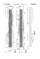
- FIG. 1 is a bottom plan view of a preferred embodiment of the upper member of the pressure sensitive switch with a conductive grid applied thereon;
- FIG. 2 is a top plan view of a preferred embodiment of the lower member of the pressure sensitive switch with the input and output conductive grid applied thereon;
- FIG. 3 is a bottom plan view of a preferred embodiment of the dielectric grid to be applied over the conductive grid and the member illustrated in FIG. 2;
- FIG. 4 is a reversible plan view of a preferred embodiment of the middle member of the pressure sensitive switch
- FIG. 5 is an exploded plan view of a preferred embodiment of the pressure sensitive switch illustrating the matrix arrangement of the conductive and dielectric grids;
- FIG. 6 is a sectional view taken along the line 6--6 of FIG. 5;
- FIG. 7 is a bottom plan view of a preferred embodiment of the pressure sensitive switch.
- the upper member 10 consists of a flat, elongated, substantially rectangular sheet 11 having lengthwise edges 13 considerably longer than its widthwise edges 15.
- An array 17 of conductive bands 19 extends substantially longitudinally on the bottom face of the sheet 11.
- the conductive bands 19 are parallel, of equal width and aligned on equally spaced centers.
- the array 17 extends substantially across the interior portion of the bottom face of the sheet 11, the length 21 and width 23 of the array 17 leaving a relatively wide perimeter portion of the bottom surface without any conductive grid.
- the array 17 of conductive bands 19 will be applied by screen painting a conductive ink on the bottom surface of the upper member 11.
- a preferred embodiment of the lower member 30 of the pressure sensitive switch also consists of a flat, elongated, substantially rectangular sheet 31, preferably of length 33 and width 35 substantially equal to the length 13 and the width 15 of the upper member 10.
- An array 37 of conductive bands is applied to the top surface of the lower member 30, the width of each of the bands of the array 37 preferably being of equal width with each other and to the conductive bands 19 of the upper member 10.
- the lower member array 37 is preferably arranged in a width-wise grid orthogonal to the upper member conductive array 17 on center lines preferably equally displaced as the center lines of the conductive bands 19 of the upper member 10.
- alternate ones 39 of the lower member conductive array 37 are discreetly connected to an electrically conductive input lead 41 while the other bands 43 of the lower member conductive array 37 are discretely connected to an electrically conductive output lead 45.
- the length 47 and width 49 of the array 37 is substantially the same as the length 21 and width 23 of the upper member array 19.
- the dielectric grid 51 preferably consists of a plurality of substantially parallel and equally spaced apart bands 53 of dielectric material arranged in a fashion such that each of the dielectric bands 53 will traverse all of the conductive bands 19, 39 and 43 when the dielectric grid 51 is applied to the lower sheet 31 and the array 37 of conductive bands 39 and 43.
- the bands 53 are preferably aligned in a 45° angular relationship with respect to the widthwise conductive bands 39 and 43.
- the length 55 and width 57 of the dielectric grid 51 is substantially equal to the length 47 and width 49 of the conductive array 37.
- the width of each dielectric band 53 is less than the width of the conductive bands 19, 39 and 43 and preferably one half the diagonal of the overlapping area of the conductive bands 19, 39 and 43.
- the middle member 70 consists of a flat, elongated, substantially rectangular sheet 71, preferably of length 73 and width 75 identical to the lengths 13 and 33 and widths 15 and 35 of the upper and lower sheets 11 and 31.
- One or more openings 77 are provided through the middle member 71.
- the openings 77 are substantially rectangular and arranged in longitudinal alignment across the middle member 70.
- the total length 79 of the openings 77 is substantially equal to the lengths 55 of the dielectric grid 51 or the lengths 21 and 47 of the arrays 17 and 37 of upper and lower member conductive bands 19, 39 and 43.
- the width 81 of the openings 77 is substantially equal to the width 57 of the dielectric grid 51 and the widths 23 and 49 of the arrays 17 and 37 of upper and lower member conductive bands 19, 39 and 43.
- FIGS. 5 and 6 the relative alignments of the upper member conductive bands 19, the dielectric bands 53 and the input and output conductive bands 39 and 43 when the upper, middle and lower members 10, 70 and 30 are laminarly arranged is shown.
- the conductive bands 19, the dielectric bands 53 and the input and output bands 39 and 43 are traversing one of the openings 77 in the middle member 70.
- the upper conductive bands 19 and lower conductive bands 39 and 43 form a matrix of squares while the dielectric bands 53 intersect alternate squares in a diagonal direction.
- alternate overlapping portions of the wider upper and lower conductive bands 19, 39 and 43 are partially separated from the possibility of electrical contact therebetween by the narrower dielectric bands 53, as can best be seen in FIG. 6. Consequently, in the preferred arrangement, only fifty percent of the matrix of overlapping points can come into full electrical contact and the remaining overlapping points can achieve electrical contact over a maximum of 50 percent of their overlapping area.
- the conductive grids are screen painted onto their respective members.
- the upper and lower members 10 and 30 will be 5 mil heat stabilized polyester and the conductive bands 19, 39 and 43 will be formed by use of a suitable conductive ink such as 50/50 graphite/silver blend.
- the input and output leads 41 and 45 of the lower member conductive bands 39 and 43 are screen painted simultaneously with the conductive bands 39 and 43.
- a dielectric ink can be used to screen the dielectric array 51 over the lower member conductive array 37.
- a plurality of arrays 37 can be screened onto a single sheet which can then be cut into a number of sheets 31.
- the openings 77 are die cut into the middle member 70 which will preferably be formed of 10 mil sheet such as a 7 mil polyester film with a 11/2 mil adhesive on each side thereof if adhesive bonding is used to accomplish lamination.
- the upper, middle and lower members 10, 70 and 30 are then laminated together, as by heat sealing or adhesively bonding the middle member 70 between the upper and lower members 10 and 30.
- FIG. 7 illustrates the upper member 10 of FIG. 1 and the lower member 30 of FIG. 2 with the dielectric array 51 of FIG. 3 superimposed thereon laminated to the middle member 70 of FIG. 3 using a clear polyester for the upper, middle and lower members 10, 70 and 30.
- the polyester need not necessarily be clear.
- the input lead 41 and the output lead 45 are extended externally of the switch to a plug 90 for connection of the switch to an appropriate electrical power and control unit (not shown).
- the device as shown is in an elongated rectangular configuration with conductive arrays 17 and 37 in orthogonal arrangement and dielectric array 51 intersecting the orthogonal conductive arrays 17 and 37 at alternate diagonals.
- this arrangement is preferred, it is not necessary that the conductive arrays 17 and 37 be in orthogonal relationship to each other or that they be on equally spaced centers.
Abstract
Description
Claims (18)
Priority Applications (10)
| Application Number | Priority Date | Filing Date | Title |
|---|---|---|---|
| US08/281,431 US5554835A (en) | 1994-07-27 | 1994-07-27 | Traversing conductor pressure sensitive switch |
| CA002194699A CA2194699C (en) | 1994-07-27 | 1995-07-25 | Pressure sensitive switch |
| GB9701632A GB2305761B (en) | 1994-07-27 | 1995-07-25 | Monitor for load bearing device |
| AU31453/95A AU3145395A (en) | 1994-07-27 | 1995-07-25 | Pressure sensitive switch |
| PCT/US1995/009385 WO1996003727A1 (en) | 1994-07-27 | 1995-07-25 | Monitor for load bearing device |
| AU32713/95A AU3271395A (en) | 1994-07-27 | 1995-07-25 | Monitor for load bearing device |
| CA002194698A CA2194698C (en) | 1994-07-27 | 1995-07-25 | Monitor for load bearing device |
| GB9701402A GB2305297B (en) | 1994-07-27 | 1995-07-25 | Pressure sensitive switch |
| PCT/US1995/009367 WO1996003726A1 (en) | 1994-07-27 | 1995-07-25 | Pressure sensitive switch |
| US08/706,744 US5623760A (en) | 1994-07-27 | 1996-09-09 | Pressure sensitive switch |
Applications Claiming Priority (1)
| Application Number | Priority Date | Filing Date | Title |
|---|---|---|---|
| US08/281,431 US5554835A (en) | 1994-07-27 | 1994-07-27 | Traversing conductor pressure sensitive switch |
Related Child Applications (1)
| Application Number | Title | Priority Date | Filing Date |
|---|---|---|---|
| US08/706,744 Continuation US5623760A (en) | 1994-07-27 | 1996-09-09 | Pressure sensitive switch |
Publications (1)
| Publication Number | Publication Date |
|---|---|
| US5554835A true US5554835A (en) | 1996-09-10 |
Family
ID=23077265
Family Applications (2)
| Application Number | Title | Priority Date | Filing Date |
|---|---|---|---|
| US08/281,431 Expired - Lifetime US5554835A (en) | 1994-07-27 | 1994-07-27 | Traversing conductor pressure sensitive switch |
| US08/706,744 Expired - Lifetime US5623760A (en) | 1994-07-27 | 1996-09-09 | Pressure sensitive switch |
Family Applications After (1)
| Application Number | Title | Priority Date | Filing Date |
|---|---|---|---|
| US08/706,744 Expired - Lifetime US5623760A (en) | 1994-07-27 | 1996-09-09 | Pressure sensitive switch |
Country Status (1)
| Country | Link |
|---|---|
| US (2) | US5554835A (en) |
Cited By (47)
| Publication number | Priority date | Publication date | Assignee | Title |
|---|---|---|---|---|
| WO1998018318A1 (en) * | 1996-10-29 | 1998-05-07 | Rentokil Initial U.K. Limited | Rodent detection apparatus |
| US5945914A (en) * | 1998-06-11 | 1999-08-31 | Bed-Check Corporation | Toilet seat occupancy monitoring apparatus |
| WO1999044180A1 (en) * | 1998-02-26 | 1999-09-02 | Bed-Check Corporation | Microprocessor based bed patient monitor |
| US5967299A (en) * | 1998-03-12 | 1999-10-19 | Molex Incorporated | Membrane switch |
| US6307476B1 (en) | 1999-04-02 | 2001-10-23 | Bed-Check Corporation | Smart binary switch for use with an electronic patient monitor |
| US6307168B1 (en) | 1999-03-23 | 2001-10-23 | Paul Newham | Linear spaced dielectric dot separator pressure sensing array incorporating strain release stabilized releasable electric snap stud connectors |
| US6417777B2 (en) | 2000-02-23 | 2002-07-09 | Bed-Check Corporation | Pressure sensitive mat with breathing tube apparatus |
| US6545236B2 (en) | 2001-02-07 | 2003-04-08 | Lear Corporation | Vehicle interior component having a flexible cover with integrated circuitry |
| US6611783B2 (en) | 2000-01-07 | 2003-08-26 | Nocwatch, Inc. | Attitude indicator and activity monitoring device |
| US20030197614A1 (en) * | 2002-04-18 | 2003-10-23 | Bed-Check Corporation | Apparatus for lighting a patient monitor front panel |
| US6696653B1 (en) | 2001-06-07 | 2004-02-24 | Bed-Check Corporation | Binary switch apparatus and method for manufacturing same |
| US20040046668A1 (en) * | 2000-06-09 | 2004-03-11 | Bed-Check Corporation | Apparatus and method for reducing the risk of decubitus ulcers |
| US6784797B2 (en) | 1998-02-26 | 2004-08-31 | Bed-Check Corporation | Microprocessor based bed patient monitor |
| US20040183681A1 (en) * | 2003-03-18 | 2004-09-23 | Bed-Check Corporation | Power latch for use with an electronic patient monitor |
| US20050011738A1 (en) * | 2003-07-14 | 2005-01-20 | Bed-Check Corporation | Sensor and method for detecting a patient's movement via position and occlusion |
| US6858811B2 (en) * | 2001-06-07 | 2005-02-22 | Bed-Check Corporation | Binary switch apparatus and method for manufacturing same |
| US20050046575A1 (en) * | 2003-08-20 | 2005-03-03 | Bed-Check Corporation | Method and apparatus for alarm volume control using pulse width modulation |
| US20050083207A1 (en) * | 2003-10-17 | 2005-04-21 | Bed-Check Corporation | Method and apparatus for monitoring a restraint device |
| US20050082466A1 (en) * | 2003-10-17 | 2005-04-21 | Bed-Check Corporation | Displacement sensor apparatus |
| US20050172398A1 (en) * | 2004-02-11 | 2005-08-11 | Bed-Check Corporation | Feedback control system to reduce the risk of pressure sores |
| US20070040692A1 (en) * | 2005-08-19 | 2007-02-22 | Bed-Check Corporation | Method and apparatus for temporarily disabling a patient monitor |
| US20070188179A1 (en) * | 2006-02-10 | 2007-08-16 | Deangelis Alfred R | Printed capacitive sensor |
| US20070186667A1 (en) * | 2006-02-10 | 2007-08-16 | Deangelis Alfred R | Printed capacitive sensor |
| US20070195703A1 (en) * | 2006-02-22 | 2007-08-23 | Living Independently Group Inc. | System and method for monitoring a site using time gap analysis |
| US20070248799A1 (en) * | 2006-02-10 | 2007-10-25 | Deangelis Alfred R | Flexible capacitive sensor |
| US7378975B1 (en) | 2000-06-09 | 2008-05-27 | Bed-Check Corporation | Method and apparatus for mitigating the risk of pressure sores |
| US20080125618A1 (en) * | 2006-11-28 | 2008-05-29 | Anderson Gregory S | Bone-activity stimulation apparatus and method |
| US20090273483A1 (en) * | 2008-04-30 | 2009-11-05 | Michael Tompkins | Flexible electroluminescent capacitive sensor |
| US7698765B2 (en) | 2004-04-30 | 2010-04-20 | Hill-Rom Services, Inc. | Patient support |
| US20100245090A1 (en) * | 2004-05-19 | 2010-09-30 | Bed-Check Corporation | Patient thermal monitoring system |
| US7849545B2 (en) | 2006-11-14 | 2010-12-14 | Hill-Rom Industries Sa | Control system for hospital bed mattress |
| US8717181B2 (en) | 2010-07-29 | 2014-05-06 | Hill-Rom Services, Inc. | Bed exit alert silence with automatic re-enable |
| US20140249354A1 (en) * | 2009-07-14 | 2014-09-04 | Pulse, Llc | Immersive, flux-guided, micro-coil apparatus and method |
| US20150303008A1 (en) * | 2014-04-21 | 2015-10-22 | Foster Electric Co., Ltd. | Cable switch |
| USD762864S1 (en) | 2014-05-13 | 2016-08-02 | Pulse, Llc | Micro-coil array |
| USD763453S1 (en) | 2014-05-13 | 2016-08-09 | Pulse, Llc | Micro-coil array |
| US9498639B2 (en) | 2014-05-13 | 2016-11-22 | Pulse, Llc | Immersive, flux-guided, micro-coil apparatus and method |
| US20170040126A1 (en) * | 2015-08-03 | 2017-02-09 | Hitachi Metals, Ltd. | Touch sensor and method for manufacturing the same |
| US20180013427A1 (en) * | 2015-01-26 | 2018-01-11 | Mitsuba Corporation | Touch sensor unit |
| US9875633B2 (en) | 2014-09-11 | 2018-01-23 | Hill-Rom Sas | Patient support apparatus |
| US10231890B2 (en) | 2014-06-06 | 2019-03-19 | Kinetic Medical Aid Innovations, Inc. | Apparatus for reducing the risk of developing decubitus ulcers and adjunct to treatment thereof on immobile patients |
| US10292605B2 (en) | 2012-11-15 | 2019-05-21 | Hill-Rom Services, Inc. | Bed load cell based physiological sensing systems and methods |
| US10504353B2 (en) | 2015-07-27 | 2019-12-10 | Hill-Rom Services, Inc. | Customized bed exit warnings to modify patient behavior |
| US10692346B2 (en) | 2018-10-22 | 2020-06-23 | Tidi Products, Llc | Electronic fall monitoring system |
| US11191975B2 (en) | 2009-07-14 | 2021-12-07 | Pulse, Llc | Micro-coil wristband |
| US11210922B2 (en) | 2018-10-22 | 2021-12-28 | Tidi Products, Llc | Electronic fall monitoring system |
| US11878181B2 (en) | 2009-07-14 | 2024-01-23 | Pulse, Llc | Micro-coil wristband |
Families Citing this family (32)
| Publication number | Priority date | Publication date | Assignee | Title |
|---|---|---|---|---|
| JP2001516124A (en) * | 1997-08-14 | 2001-09-25 | ドラフテックス インダストリーズ リミティド | Force responsive detector and device |
| GB2335310B (en) * | 1998-03-11 | 2001-09-19 | Draftex Ind Ltd | Force-responsive detectors and systems |
| US6933469B2 (en) | 2000-06-14 | 2005-08-23 | American Healthcare Products, Inc. | Personal warming systems and apparatuses for use in hospitals and other settings, and associated methods of manufacture and use |
| US7656299B2 (en) * | 2007-01-17 | 2010-02-02 | Hoana Medical, Inc. | Bed exit and patient detection system |
| US7666151B2 (en) * | 2002-11-20 | 2010-02-23 | Hoana Medical, Inc. | Devices and methods for passive patient monitoring |
| US6329617B1 (en) * | 2000-09-19 | 2001-12-11 | Lester E. Burgess | Pressure activated switching device |
| US7253366B2 (en) * | 2004-08-09 | 2007-08-07 | Hill-Rom Services, Inc. | Exit alarm for a hospital bed triggered by individual load cell weight readings exceeding a predetermined threshold |
| US8090478B2 (en) | 2005-06-10 | 2012-01-03 | Hill-Rom Services, Inc. | Control for pressurized bladder in a patient support apparatus |
| CL2008000704A1 (en) * | 2007-03-12 | 2008-09-12 | Lma Medical Innovations Ltd | PROCEDURE FOR HEATING AN INTRAVENOUS FLUID THAT INCLUDES THE CONNECTION OF A HEATING ELEMENT, ELECTRICALLY RESISTANT, TO A FLUID SUPPLY LINE, ELECTRICALLY COUPLING A POWER SOURCE TO THE HEATING ELEMENT, ELECTRICALLY RESISTOR; |
| US20090099480A1 (en) * | 2007-05-24 | 2009-04-16 | Peter Salgo | System and method for patient monitoring |
| US8533879B1 (en) | 2008-03-15 | 2013-09-17 | Stryker Corporation | Adaptive cushion method and apparatus for minimizing force concentrations on a human body |
| US8161826B1 (en) | 2009-03-05 | 2012-04-24 | Stryker Corporation | Elastically stretchable fabric force sensor arrays and methods of making |
| CA2720861C (en) * | 2008-04-10 | 2017-01-03 | Carroll Hospital Group Inc. | Signaling device for detecting the presence of an object |
| US8134473B2 (en) | 2008-04-10 | 2012-03-13 | Chg Hospital Beds Inc. | Signaling device for detecting the presence of an object |
| US11278237B2 (en) | 2010-04-22 | 2022-03-22 | Leaf Healthcare, Inc. | Devices, systems, and methods for preventing, detecting, and treating pressure-induced ischemia, pressure ulcers, and other conditions |
| US9728061B2 (en) | 2010-04-22 | 2017-08-08 | Leaf Healthcare, Inc. | Systems, devices and methods for the prevention and treatment of pressure ulcers, bed exits, falls, and other conditions |
| US10020075B2 (en) | 2009-03-24 | 2018-07-10 | Leaf Healthcare, Inc. | Systems and methods for monitoring and/or managing patient orientation using a dynamically adjusted relief period |
| US10631732B2 (en) | 2009-03-24 | 2020-04-28 | Leaf Healthcare, Inc. | Systems and methods for displaying sensor-based user orientation information |
| US9655546B2 (en) | 2010-04-22 | 2017-05-23 | Leaf Healthcare, Inc. | Pressure Ulcer Detection Methods, Devices and Techniques |
| US11272860B2 (en) | 2010-04-22 | 2022-03-15 | Leaf Healthcare, Inc. | Sensor device with a selectively activatable display |
| US11369309B2 (en) | 2010-04-22 | 2022-06-28 | Leaf Healthcare, Inc. | Systems and methods for managing a position management protocol based on detected inclination angle of a person |
| JP6192032B2 (en) | 2010-04-22 | 2017-09-06 | リーフ ヘルスケア インコーポレイテッド | A system for monitoring a patient's physiological status |
| US10588565B2 (en) | 2010-04-22 | 2020-03-17 | Leaf Healthcare, Inc. | Calibrated systems, devices and methods for preventing, detecting, and treating pressure-induced ischemia, pressure ulcers, and other conditions |
| US10140837B2 (en) | 2010-04-22 | 2018-11-27 | Leaf Healthcare, Inc. | Systems, devices and methods for the prevention and treatment of pressure ulcers, bed exits, falls, and other conditions |
| US10758162B2 (en) | 2010-04-22 | 2020-09-01 | Leaf Healthcare, Inc. | Systems, devices and methods for analyzing a person status based at least on a detected orientation of the person |
| US11051751B2 (en) | 2010-04-22 | 2021-07-06 | Leaf Healthcare, Inc. | Calibrated systems, devices and methods for preventing, detecting, and treating pressure-induced ischemia, pressure ulcers, and other conditions |
| US20140059778A1 (en) * | 2012-08-30 | 2014-03-06 | Ronald B. Jalbert | Interface pressure sensing mattress |
| US8904876B2 (en) | 2012-09-29 | 2014-12-09 | Stryker Corporation | Flexible piezocapacitive and piezoresistive force and pressure sensors |
| US8997588B2 (en) | 2012-09-29 | 2015-04-07 | Stryker Corporation | Force detecting mat with multiple sensor types |
| GB2508626B (en) | 2012-12-05 | 2014-10-29 | R & D Core Ltd | Contact sensor |
| GB2510600B (en) | 2013-02-08 | 2015-05-20 | R & D Core Ltd | Calibration of Contact Sensor |
| US9408939B2 (en) | 2013-03-15 | 2016-08-09 | Medline Industries, Inc. | Anti-microbial air processor for a personal patient warming apparatus |
Citations (7)
| Publication number | Priority date | Publication date | Assignee | Title |
|---|---|---|---|---|
| US3812313A (en) * | 1973-02-20 | 1974-05-21 | Switches Inc | Tread type switch for use in passenger seats or the like |
| US4154178A (en) * | 1978-02-21 | 1979-05-15 | The Singer Company | High density programming means for programmable sewing machine |
| US4484043A (en) * | 1982-09-30 | 1984-11-20 | Bed-Check Corporation | Switch apparatus responsive to pressure or distortion |
| US4539445A (en) * | 1982-12-20 | 1985-09-03 | At&T Technologies, Inc. | Click disc switch assembly |
| US4565910A (en) * | 1982-09-30 | 1986-01-21 | Bed-Check Corporation | Switch apparatus responsive to distortion |
| US4621178A (en) * | 1981-02-19 | 1986-11-04 | Sharp Kabushiki Kaisha | Microwave oven having a keyboard of the membrane type |
| US5047602A (en) * | 1989-05-17 | 1991-09-10 | G. Bopp & Co. Ag | Pressure-sensitive mat-form electric switching element |
Family Cites Families (2)
| Publication number | Priority date | Publication date | Assignee | Title |
|---|---|---|---|---|
| GB1390396A (en) * | 1972-07-21 | 1975-04-09 | Amf Inc | Gas heated rotary drier |
| DE3507922A1 (en) * | 1985-03-06 | 1986-09-11 | Mayser-Gmbh & Co, 7900 Ulm | SHIFTING MAT AND METHOD FOR THEIR PRODUCTION |
-
1994
- 1994-07-27 US US08/281,431 patent/US5554835A/en not_active Expired - Lifetime
-
1996
- 1996-09-09 US US08/706,744 patent/US5623760A/en not_active Expired - Lifetime
Patent Citations (7)
| Publication number | Priority date | Publication date | Assignee | Title |
|---|---|---|---|---|
| US3812313A (en) * | 1973-02-20 | 1974-05-21 | Switches Inc | Tread type switch for use in passenger seats or the like |
| US4154178A (en) * | 1978-02-21 | 1979-05-15 | The Singer Company | High density programming means for programmable sewing machine |
| US4621178A (en) * | 1981-02-19 | 1986-11-04 | Sharp Kabushiki Kaisha | Microwave oven having a keyboard of the membrane type |
| US4484043A (en) * | 1982-09-30 | 1984-11-20 | Bed-Check Corporation | Switch apparatus responsive to pressure or distortion |
| US4565910A (en) * | 1982-09-30 | 1986-01-21 | Bed-Check Corporation | Switch apparatus responsive to distortion |
| US4539445A (en) * | 1982-12-20 | 1985-09-03 | At&T Technologies, Inc. | Click disc switch assembly |
| US5047602A (en) * | 1989-05-17 | 1991-09-10 | G. Bopp & Co. Ag | Pressure-sensitive mat-form electric switching element |
Cited By (79)
| Publication number | Priority date | Publication date | Assignee | Title |
|---|---|---|---|---|
| WO1998018318A1 (en) * | 1996-10-29 | 1998-05-07 | Rentokil Initial U.K. Limited | Rodent detection apparatus |
| US6784797B2 (en) | 1998-02-26 | 2004-08-31 | Bed-Check Corporation | Microprocessor based bed patient monitor |
| WO1999044180A1 (en) * | 1998-02-26 | 1999-09-02 | Bed-Check Corporation | Microprocessor based bed patient monitor |
| US6111509A (en) * | 1998-02-26 | 2000-08-29 | Bed-Check Corporation | Microprocessor based bed patient monitor |
| US5967299A (en) * | 1998-03-12 | 1999-10-19 | Molex Incorporated | Membrane switch |
| US5945914A (en) * | 1998-06-11 | 1999-08-31 | Bed-Check Corporation | Toilet seat occupancy monitoring apparatus |
| WO1999063876A1 (en) | 1998-06-11 | 1999-12-16 | Bed-Check Corporation | Toilet seat occupancy monitoring apparatus |
| US6307168B1 (en) | 1999-03-23 | 2001-10-23 | Paul Newham | Linear spaced dielectric dot separator pressure sensing array incorporating strain release stabilized releasable electric snap stud connectors |
| US6307476B1 (en) | 1999-04-02 | 2001-10-23 | Bed-Check Corporation | Smart binary switch for use with an electronic patient monitor |
| US6611783B2 (en) | 2000-01-07 | 2003-08-26 | Nocwatch, Inc. | Attitude indicator and activity monitoring device |
| US6417777B2 (en) | 2000-02-23 | 2002-07-09 | Bed-Check Corporation | Pressure sensitive mat with breathing tube apparatus |
| US7030764B2 (en) | 2000-06-09 | 2006-04-18 | Bed-Check Corporation | Apparatus and method for reducing the risk of decubitus ulcers |
| US20040046668A1 (en) * | 2000-06-09 | 2004-03-11 | Bed-Check Corporation | Apparatus and method for reducing the risk of decubitus ulcers |
| US7378975B1 (en) | 2000-06-09 | 2008-05-27 | Bed-Check Corporation | Method and apparatus for mitigating the risk of pressure sores |
| US6545236B2 (en) | 2001-02-07 | 2003-04-08 | Lear Corporation | Vehicle interior component having a flexible cover with integrated circuitry |
| US6858811B2 (en) * | 2001-06-07 | 2005-02-22 | Bed-Check Corporation | Binary switch apparatus and method for manufacturing same |
| US6696653B1 (en) | 2001-06-07 | 2004-02-24 | Bed-Check Corporation | Binary switch apparatus and method for manufacturing same |
| US20030197614A1 (en) * | 2002-04-18 | 2003-10-23 | Bed-Check Corporation | Apparatus for lighting a patient monitor front panel |
| US6864795B2 (en) | 2002-04-18 | 2005-03-08 | Bed-Check Corporation | Apparatus for lighting a patient monitor front panel |
| US20040183681A1 (en) * | 2003-03-18 | 2004-09-23 | Bed-Check Corporation | Power latch for use with an electronic patient monitor |
| US6998986B2 (en) | 2003-03-18 | 2006-02-14 | Bed-Check Corporation | Power latch for use with an electronic patient monitor |
| US20050011738A1 (en) * | 2003-07-14 | 2005-01-20 | Bed-Check Corporation | Sensor and method for detecting a patient's movement via position and occlusion |
| US7079036B2 (en) | 2003-08-20 | 2006-07-18 | Bed-Check Corporation | Method and apparatus for alarm volume control using pulse width modulation |
| US20050046575A1 (en) * | 2003-08-20 | 2005-03-03 | Bed-Check Corporation | Method and apparatus for alarm volume control using pulse width modulation |
| US20050083207A1 (en) * | 2003-10-17 | 2005-04-21 | Bed-Check Corporation | Method and apparatus for monitoring a restraint device |
| US7319400B2 (en) | 2003-10-17 | 2008-01-15 | Bed-Check Corporation | Method and apparatus for monitoring a restraint device |
| US7078676B2 (en) | 2003-10-17 | 2006-07-18 | Bed-Check Corporation | Displacement sensor apparatus |
| US20050082466A1 (en) * | 2003-10-17 | 2005-04-21 | Bed-Check Corporation | Displacement sensor apparatus |
| US20050172398A1 (en) * | 2004-02-11 | 2005-08-11 | Bed-Check Corporation | Feedback control system to reduce the risk of pressure sores |
| US7698765B2 (en) | 2004-04-30 | 2010-04-20 | Hill-Rom Services, Inc. | Patient support |
| US8146191B2 (en) | 2004-04-30 | 2012-04-03 | Hill-Rom Services, Inc. | Patient support |
| US20100245090A1 (en) * | 2004-05-19 | 2010-09-30 | Bed-Check Corporation | Patient thermal monitoring system |
| US7570152B2 (en) | 2005-08-19 | 2009-08-04 | Bed-Check Corporation | Method and apparatus for temporarily disabling a patient monitor |
| US20070040692A1 (en) * | 2005-08-19 | 2007-02-22 | Bed-Check Corporation | Method and apparatus for temporarily disabling a patient monitor |
| US20080127739A1 (en) * | 2006-02-10 | 2008-06-05 | Deangelis Alfred R | Capacitive sensor |
| US20070186667A1 (en) * | 2006-02-10 | 2007-08-16 | Deangelis Alfred R | Printed capacitive sensor |
| US7368921B2 (en) | 2006-02-10 | 2008-05-06 | Milliken & Company | Printed capacitive sensor |
| US20070248799A1 (en) * | 2006-02-10 | 2007-10-25 | Deangelis Alfred R | Flexible capacitive sensor |
| US7301351B2 (en) | 2006-02-10 | 2007-11-27 | Milliken & Company | Printed capacitive sensor |
| US7276917B2 (en) | 2006-02-10 | 2007-10-02 | Milliken & Company | Printed capacitive sensor |
| US7395717B2 (en) | 2006-02-10 | 2008-07-08 | Milliken & Company | Flexible capacitive sensor |
| US7578195B2 (en) | 2006-02-10 | 2009-08-25 | Milliken & Company | Capacitive sensor |
| US20070188179A1 (en) * | 2006-02-10 | 2007-08-16 | Deangelis Alfred R | Printed capacitive sensor |
| US20070188180A1 (en) * | 2006-02-10 | 2007-08-16 | Deangelis Alfred R | Printed capacitive sensor |
| US20070195703A1 (en) * | 2006-02-22 | 2007-08-23 | Living Independently Group Inc. | System and method for monitoring a site using time gap analysis |
| US7849545B2 (en) | 2006-11-14 | 2010-12-14 | Hill-Rom Industries Sa | Control system for hospital bed mattress |
| US8758216B2 (en) * | 2006-11-28 | 2014-06-24 | Gregory S. Anderson | Electromagnetic body tissue stimulation apparatus and method |
| US8147395B2 (en) * | 2006-11-28 | 2012-04-03 | Gregory S. Anderson | Bone-activity stimulation apparatus and method |
| US20080125618A1 (en) * | 2006-11-28 | 2008-05-29 | Anderson Gregory S | Bone-activity stimulation apparatus and method |
| US7719007B2 (en) | 2008-04-30 | 2010-05-18 | Milliken & Company | Flexible electroluminescent capacitive sensor |
| US20090273483A1 (en) * | 2008-04-30 | 2009-11-05 | Michael Tompkins | Flexible electroluminescent capacitive sensor |
| US10507333B2 (en) * | 2009-07-14 | 2019-12-17 | Pulse, Llc | Immersive, flux-guided, micro-coil apparatus and method |
| US11878181B2 (en) | 2009-07-14 | 2024-01-23 | Pulse, Llc | Micro-coil wristband |
| US11844956B2 (en) | 2009-07-14 | 2023-12-19 | Pulse, Llc | Immersive, flux-guided, micro-coil apparatus and method |
| US11191975B2 (en) | 2009-07-14 | 2021-12-07 | Pulse, Llc | Micro-coil wristband |
| US20140249354A1 (en) * | 2009-07-14 | 2014-09-04 | Pulse, Llc | Immersive, flux-guided, micro-coil apparatus and method |
| US8717181B2 (en) | 2010-07-29 | 2014-05-06 | Hill-Rom Services, Inc. | Bed exit alert silence with automatic re-enable |
| US10292605B2 (en) | 2012-11-15 | 2019-05-21 | Hill-Rom Services, Inc. | Bed load cell based physiological sensing systems and methods |
| US9564276B2 (en) * | 2014-04-21 | 2017-02-07 | Foster Electric Co., Ltd. | Cable switch |
| CN105023776B (en) * | 2014-04-21 | 2018-09-25 | 丰达电机株式会社 | Cable switchs |
| US20150303008A1 (en) * | 2014-04-21 | 2015-10-22 | Foster Electric Co., Ltd. | Cable switch |
| US9498639B2 (en) | 2014-05-13 | 2016-11-22 | Pulse, Llc | Immersive, flux-guided, micro-coil apparatus and method |
| USD763453S1 (en) | 2014-05-13 | 2016-08-09 | Pulse, Llc | Micro-coil array |
| US11213692B2 (en) | 2014-05-13 | 2022-01-04 | Pulse, Llc | Body-conforming, micro-coil, web apparatus and method |
| US10537747B2 (en) | 2014-05-13 | 2020-01-21 | Pulse, Llc | Immersive, flux-guided, micro-coil apparatus and method |
| USD762864S1 (en) | 2014-05-13 | 2016-08-02 | Pulse, Llc | Micro-coil array |
| US11813473B2 (en) | 2014-05-13 | 2023-11-14 | Newage, Inc. | Body-conforming, micro-coil, web apparatus and method |
| US10231890B2 (en) | 2014-06-06 | 2019-03-19 | Kinetic Medical Aid Innovations, Inc. | Apparatus for reducing the risk of developing decubitus ulcers and adjunct to treatment thereof on immobile patients |
| US10276021B2 (en) | 2014-09-11 | 2019-04-30 | Hill-Rom Sas | Patient support apparatus having articulated mattress support deck with load sensors |
| US9875633B2 (en) | 2014-09-11 | 2018-01-23 | Hill-Rom Sas | Patient support apparatus |
| US10075162B2 (en) * | 2015-01-26 | 2018-09-11 | Mitsuba Corporation | Touch sensor unit |
| US20180013427A1 (en) * | 2015-01-26 | 2018-01-11 | Mitsuba Corporation | Touch sensor unit |
| US10504353B2 (en) | 2015-07-27 | 2019-12-10 | Hill-Rom Services, Inc. | Customized bed exit warnings to modify patient behavior |
| US11282365B2 (en) | 2015-07-27 | 2022-03-22 | Hill-Rom Services, Inc. | Customized bed exit warnings to modify patient behavior |
| US20170040126A1 (en) * | 2015-08-03 | 2017-02-09 | Hitachi Metals, Ltd. | Touch sensor and method for manufacturing the same |
| US9984832B2 (en) * | 2015-08-03 | 2018-05-29 | Hitachi Metals, Ltd. | Touch sensor and method for manufacturing the same |
| US11776374B2 (en) | 2018-10-22 | 2023-10-03 | Tidi Products, Llc | Electronic fall monitoring system |
| US11210922B2 (en) | 2018-10-22 | 2021-12-28 | Tidi Products, Llc | Electronic fall monitoring system |
| US10692346B2 (en) | 2018-10-22 | 2020-06-23 | Tidi Products, Llc | Electronic fall monitoring system |
Also Published As
| Publication number | Publication date |
|---|---|
| US5623760A (en) | 1997-04-29 |
Similar Documents
| Publication | Publication Date | Title |
|---|---|---|
| US5554835A (en) | Traversing conductor pressure sensitive switch | |
| US4491760A (en) | Force sensing polymer piezoelectric transducer array | |
| US4065197A (en) | Isolated paths connector | |
| US6307168B1 (en) | Linear spaced dielectric dot separator pressure sensing array incorporating strain release stabilized releasable electric snap stud connectors | |
| AU550043B2 (en) | Electrode structure | |
| CA2046663A1 (en) | Flexible, tactile sensor for measuring foot pressure distributions and for gaskets | |
| EP0252756A3 (en) | Semiconductor device comprising an organic material | |
| CA2113958A1 (en) | Semiconductor device and method for manufacturing the same | |
| GB2328319B (en) | A frequency selective surface | |
| KR20000023303A (en) | Detector constructed from fabric | |
| EP1308961A3 (en) | Memory cell structure | |
| JPS5873921A (en) | Capacitive key switch | |
| US4440990A (en) | Membrane keyboard assembly | |
| EP0118468A1 (en) | Enlarged switch area membrane switch and method | |
| WO1998057226A3 (en) | Substrate having a unidirectional conductivity perpendicular to its surface, devices comprising such a substrate and methods for manufacturing such a substrate | |
| US4994634A (en) | Sheet switch | |
| GB2081977A (en) | Input switch arrangement | |
| EP0121544A1 (en) | Device for measuring the presence of electrical conducting liquid received therein | |
| GB2095892A (en) | High capacitance bus bar | |
| GB2077508A (en) | Variable resistance pressure- sensitive laminate | |
| EP0054406A1 (en) | Writing pad for a character recognition device | |
| JPS6110203A (en) | Organic positive temperature coefficient thermistor | |
| ATE74480T1 (en) | ELECTRICAL CONTACT BETWEEN ELEMENTS WITH DIFFERENT SPECIFIC RESISTANCES. | |
| CA2074862A1 (en) | Oxygen sensor | |
| EP0838897A3 (en) | Piezoelectric resonator and electronic component comprising the piezoelectric resonator |
Legal Events
| Date | Code | Title | Description |
|---|---|---|---|
| AS | Assignment |
Owner name: BED-CHECK CORPORATION, OKLAHOMA Free format text: ASSIGNMENT OF ASSIGNORS INTEREST;ASSIGNOR:NEWHAM, PAUL F.;REEL/FRAME:007092/0218 Effective date: 19940727 |
|
| STCF | Information on status: patent grant |
Free format text: PATENTED CASE |
|
| FPAY | Fee payment |
Year of fee payment: 4 |
|
| AS | Assignment |
Owner name: J. T. POSEY COMPANY, CALIFORNIA Free format text: SETTLEMENT AGREEMENT AFFECTING PATENT RIGHTS;ASSIGNOR:BED-CHECK CORPORATION;REEL/FRAME:013974/0402 Effective date: 20030115 |
|
| FPAY | Fee payment |
Year of fee payment: 8 |
|
| FEPP | Fee payment procedure |
Free format text: PAYOR NUMBER ASSIGNED (ORIGINAL EVENT CODE: ASPN); ENTITY STATUS OF PATENT OWNER: LARGE ENTITY |
|
| FEPP | Fee payment procedure |
Free format text: PAT HOLDER NO LONGER CLAIMS SMALL ENTITY STATUS, ENTITY STATUS SET TO UNDISCOUNTED (ORIGINAL EVENT CODE: STOL); ENTITY STATUS OF PATENT OWNER: LARGE ENTITY |
|
| FPAY | Fee payment |
Year of fee payment: 12 |