US5557625A - Coupled-cavity resonator to improve the intensity profile of a laser beam - Google Patents
Coupled-cavity resonator to improve the intensity profile of a laser beam Download PDFInfo
- Publication number
- US5557625A US5557625A US08/368,989 US36898995A US5557625A US 5557625 A US5557625 A US 5557625A US 36898995 A US36898995 A US 36898995A US 5557625 A US5557625 A US 5557625A
- Authority
- US
- United States
- Prior art keywords
- optical cavity
- laser
- active
- laser beam
- active optical
- Prior art date
- Legal status (The legal status is an assumption and is not a legal conclusion. Google has not performed a legal analysis and makes no representation as to the accuracy of the status listed.)
- Expired - Fee Related
Links
Images


Classifications
-
- H—ELECTRICITY
- H01—ELECTRIC ELEMENTS
- H01S—DEVICES USING THE PROCESS OF LIGHT AMPLIFICATION BY STIMULATED EMISSION OF RADIATION [LASER] TO AMPLIFY OR GENERATE LIGHT; DEVICES USING STIMULATED EMISSION OF ELECTROMAGNETIC RADIATION IN WAVE RANGES OTHER THAN OPTICAL
- H01S3/00—Lasers, i.e. devices using stimulated emission of electromagnetic radiation in the infrared, visible or ultraviolet wave range
- H01S3/05—Construction or shape of optical resonators; Accommodation of active medium therein; Shape of active medium
- H01S3/08—Construction or shape of optical resonators or components thereof
- H01S3/081—Construction or shape of optical resonators or components thereof comprising three or more reflectors
- H01S3/082—Construction or shape of optical resonators or components thereof comprising three or more reflectors defining a plurality of resonators, e.g. for mode selection or suppression
-
- H—ELECTRICITY
- H01—ELECTRIC ELEMENTS
- H01S—DEVICES USING THE PROCESS OF LIGHT AMPLIFICATION BY STIMULATED EMISSION OF RADIATION [LASER] TO AMPLIFY OR GENERATE LIGHT; DEVICES USING STIMULATED EMISSION OF ELECTROMAGNETIC RADIATION IN WAVE RANGES OTHER THAN OPTICAL
- H01S3/00—Lasers, i.e. devices using stimulated emission of electromagnetic radiation in the infrared, visible or ultraviolet wave range
- H01S3/05—Construction or shape of optical resonators; Accommodation of active medium therein; Shape of active medium
- H01S3/08—Construction or shape of optical resonators or components thereof
- H01S3/08018—Mode suppression
- H01S3/0804—Transverse or lateral modes
-
- H—ELECTRICITY
- H01—ELECTRIC ELEMENTS
- H01S—DEVICES USING THE PROCESS OF LIGHT AMPLIFICATION BY STIMULATED EMISSION OF RADIATION [LASER] TO AMPLIFY OR GENERATE LIGHT; DEVICES USING STIMULATED EMISSION OF ELECTROMAGNETIC RADIATION IN WAVE RANGES OTHER THAN OPTICAL
- H01S3/00—Lasers, i.e. devices using stimulated emission of electromagnetic radiation in the infrared, visible or ultraviolet wave range
- H01S3/10—Controlling the intensity, frequency, phase, polarisation or direction of the emitted radiation, e.g. switching, gating, modulating or demodulating
- H01S3/11—Mode locking; Q-switching; Other giant-pulse techniques, e.g. cavity dumping
- H01S3/1123—Q-switching
- H01S3/115—Q-switching using intracavity electro-optic devices
Definitions
- an active laser medium is placed in an optical resonator or cavity comprising a set of mirrors.
- the active laser medium being a gas, a liquid or a solid, or a combination thereof, contains the active atoms, ions, molecules or particles of matter that will generate the laser beam.
- This active medium is excited through transfer of external energy to active elements of the medium by some means such as an electrical discharge, an external source of light, a chemical reaction or any source of energy.
- the elements which may be active atoms, ions, molecules or particles of matter, radiate some energy in the form of electromagnetic radiation or light. If this same light is partly or totally re-injected into the excited active laser medium, it stimulates the emission of additional light according to the principle of the stimulated emission process. As illustrated in FIG. 1, this is typically done by placing the active laser medium 1 inside an optical resonator or cavity formed by mirror 2 and a partially reflecting mirror 3. The generated laser beam is emitted through the mirror 3.
- optical resonators including wave-guide, ring, and stable and unstable configurations have been designed to achieve better quality laser beams or laser beams with specific characteristics such as single transverse or spatial mode, single longitudinal or frequency mode, or to better control some of the characteristics of the laser beam.
- Laser sources have also been used in a cascade configuration, where one well controlled laser source is used to control the subsequent ones, such as in a Master-Oscillator-Power-Amplifier or a seed-injected laser.
- some minute inhomogeneities or perturbations inside the laser resonator can greatly deteriorate some of the characteristics of the laser beam.
- a solid-state laser in which the active laser medium is a solid single crystal containing some active ions.
- some minute optical inhomogeneities due for example to minute optical imperfections in the active crystal or other optical elements, or minute inhomogeneities in the excitation process and non-uniform excitation of the active laser medium, can lead to some unpredicted perturbations in the laser beam.
- hot-spots This can sometimes generate some relatively strong variations in the spatial or cross-sectional or temporal intensity profile of the laser beam known as "hot-spots.” These “hot-spots" can be described as local areas in the cross section of the laser beam or in the temporal intensity profile where the intensity of the laser beam greatly exceeds its average or expected value. Such "hot-spots" are usually undesirable, as they can lead to unwanted and unpredictable optical damages in the laser source itself or in other components, or unwanted and unpredictable effects in the use of the laser beam.
- a specific optical design of the laser resonator prevents the formation of such "hot-spots" in the spatial and temporal intensity distributions of a laser beam.
- the active laser cavity with the active laser medium is optically coupled to a secondary optical cavity.
- the secondary optical cavity be a passive cavity such as a free-space cavity; that is, it is not an active cavity where laser emission takes place for optical gain. It is also preferred that the laser beam generated in and emitted from the active optical cavity include higher order transverse (spatial) modes and that the two cavities be mismatched at all transverse modes.
- the secondary optical cavity modifies the spatial and/or temporal characteristics of the laser beam.
- this design can be used to prevent the formation of "hot-spots" in the laser beam cross-sectional or temporal intensity profile by providing a mismatch between the cavities at a main mode of the output beam which results in the "hot spots.”
- the light emitted by the excited active laser medium is partly coupled into the passive optical cavity before being re-injected into the excited active laser medium.
- the spatial modes are filtered and mixed to some degree, leading to a spatial and temporal homogenization of the laser beam.
- the passive optical cavity is oriented axially in line with the active optical cavity. In another embodiment, the passive optical cavity is transversely oriented relative to the active optical cavity. There, the passive optical cavity is coupled to the active optical cavity by a beam splitter in the active optical cavity.
- the preferred beam splitter is a flat piece of uncoated optical glass oriented with respect to the axis of the laser beam in a manner such that the plane of incidence defined by the incident and reflected beams contains a plane of polarization of the laser beam generated in the active optical cavity.
- the passive optical cavity may include first and second reflectors positioned with the beam splitter therebetween.
- the active laser cavity may include a Q-switching element.
- FIG. 1 is a schematic illustration of a standard linear laser resonator design.
- FIG. 2 is a schematic illustration of a cross-coupled-cavity laser resonator design.
- FIG. 3 is a schematic illustration of a longitudinal-coupled-cavity laser resonator design.
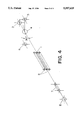
- FIG. 4 is a perspective view of a Q-switched Alexandrite laser resonator embodying the invention with a cross-coupled-cavity design.
- FIG. 5 illustrates a typical spatial intensity profile of a Q-switch Alexandrite laser beam generated using a standard linear resonator as illustrated in FIG. 1.
- FIG. 6 illustrates a typical spatial intensity profile of a Q-switch Alexandrite laser beam generated using a preferred embodiment of the invention as illustrated in FIG. 4.
- FIG. 2 One embodiment of the invention is illustrated in FIG. 2.
- an optical cavity is formed between a totally reflecting mirror 2 and a partially reflecting mirror 3.
- the mirrors may be flat, convex or concave.
- the mirror 2 is concave, typically with a radius of curvature between 0.1 meters and 10 meters, and the partially reflecting mirror 3 is flat.
- the partially reflecting mirror typically reflects between 10% and 90% of the laser beam, and in a preferred system about 40% of the light is reflected.
- a passive optical cavity comprising mirrors 5 and 6 is optically coupled to the active optical cavity by means of a partially reflecting beam-splitter 4.
- the mirrors 5 and 6 may be flat, it is preferred that they be concave, preferably with a radius of curvature between 0.1 meter and 10 meters.
- the partially reflecting mirror 4 may reflect a percentage of light within a great range, preferably less than 90% and most preferably about 10%.
- the laser beam generated by the active optical cavity comprises resonant modes of different wavelength, spatial and temporal characteristics. "Hot spots" occur from those modes having an exceptionally high gain in the active optical cavity.
- the active and passive cavities have different resonant modes in view of their different geometry and dimensions, and the passive cavity geometry and dimensions can be selected such that the modes which create the "hot spots" in the active optical cavity are attenuated in the passive optical cavity. At least a portion of the light from the passive optical cavity is then reinjected into the active optical cavity, interfering with the high resonance at the "hot spots.” In simple terms, light which is otherwise resonating at the "hot spots" is spatially redistributed by the passive cavity.
- each cavity has its own resonant modes and can be expected to attenuate the modes which create the "hot spots.”
- the beam-splitter 4 may be oriented at any angle with the passive cavity reoriented accordingly.
- the passive optical cavity can be aligned axially with the active optical cavity as illustrated in FIG. 3.
- the beam-splitter 4 and two high reflectance mirrors 5 and 6 are replaced by a partially reflecting mirror 9. All the other elements may be identical in form and position as described above.
- the active optical cavity between reflectors 2 and 3 there is an additional passive cavity between reflectors 3 and 9 as well as yet another cavity between reflectors 2 and 9.
- the partially reflecting mirror 9 has a concave radius of curvature of one meter facing the active laser medium 1 and a convex radius of curvature of one meter facing opposite the active laser medium, and the mirror has a reflectivity of 10%.
- the partially reflecting mirror 9 is located a distance of 50 millimeters from the partially reflecting mirror 3.
- a wide range of mirror types and distances provide the desired attenuation of "hot spots.”
- a laser whose beam has a diffraction limit greater than or equal to 2 has higher transverse (spatial) modes. Where the diffraction limit is less than 2, the laser has only low order transverse modes.
- an aperture may be positioned anywhere within the passive cavity to fully block the radiation from the "hot spots.”
- the active laser medium 1 is a cylindrical laser rod of Alexandrite Be(Al 1-x Cr x ) 2 O 4 crystal in which the Cr 3+ ions are the active elements responsible for the emission of lights around 752 nm. These Cr 3+ ions are optically excited or pumped by two linear flash-lamps 8 located parallel to the laser rod and on opposite sides as illustrated in FIG. 4.
- the laser rod is 10.16 cm long and 6.35 mm in diameter, and the flash lamps have an arc length of 8.89 cm and a bore diameter of 5 mm.
- the two flash lamps and the laser rod are mounted inside a close-coupled diffuse reflector to provide efficient optical coupling between the flash lamps and the laser rod and therefore an efficient pumping or excitation of the Cr 3+ ions.
- the laser rod is oriented so that the polarization of the generated laser beam is in a plane perpendicular to the plane containing the two flash lamps.
- the active laser cavity is formed by a high reflecting mirror 2 having a concave radius of curvature of 3 m and a flat partially reflecting mirror 3 reflecting 40% of the light emitted by the laser rod.
- the two mirrors are separated by a distance of 0.44 m, and the middle of the laser rod is located 0.22 m from the high reflecting mirror.
- an electro-optic Pockels cell 7 is inserted inside the active cavity with its optical axes oriented at 45° with respect to the polarization plane of the light emitted by the laser rod.
- a high voltage of approximately 1,800 V is applied across this Pockels cell, it introduces an optical retardation in the light emitted by the laser rod effectively resulting in a rotation of 90° of the polarization plane of said light after it travels from the laser rod through the Pockels cell to the High Reflector and back through the Pockels cell to the laser rod.
- the returning light having its polarization plane shifted at 90° with respect to the originally emitted light is not amplified through the excited laser rod. This results in the lack of laser beam generation.
- time duration of the laser pulse is of the order of 40 nsec to 200 nsec, and depends on the amount of energy that is stored and released by the Cr 3+ ions. Repetition rate may be between 1 Hz and 10 Hz.
- the pulse energy generated by this laser system varies between 0.1 J and 1 J.
- the spatial intensity profile of the laser beam exhibits some "hot-spots" as illustrated in FIG. 5.
- the active cavity is coupled to a passive cavity by the use of a 45° beam-splitter 4 consisting of a flat uncoated piece of optical glass located 50 mm from the flat partially reflecting mirror 3 and at mid-distance between the two mirrors of the passive cavity 5 and 6.
- the passive cavity is formed by two high reflectance mirrors 5 and 6 having a concave radius of curvature of 3 m, separated by a distance of 50 mm, and located equidistant from the beam-splitter 4.
- this piece of glass When this piece of glass is oriented at 45° with respect to the laser beam axis, such that the passive optical cavity is oriented at 90°, and further in a manner such that the plane of incidence defined by the incident and reflected beams contains the polarization of the light emitted by the laser rod as illustrated in FIG. 4, it reflects approximately 8% of the incident light on each surface.
- the glass were oriented such that the plane of incidence is perpendicular to the polarization, only about 1% of the light would be reflected.
- reflection can be made independent of that orientation by the use of suitable coatings on the glass.
- This reflected light then resonates inside the passive cavity formed by the two mirrors 5 and 6, and a fraction of it is reflected by the same beam-splitter 4 back into the active cavity.
- the coupling of the two cavities results in a spatial filtering and mixing of the different spatial modes of the light emitted by the laser rod. This process is most important in a Q-switched laser during the initial build-up of the giant laser pulse following immediately the switching from a low Q factor to a high Q factor of the laser cavity.
- the giant laser pulse generated by this invention exhibits a smooth spatial beam profile as illustrated in FIG. 6.
Abstract
Description
Claims (41)
Priority Applications (1)
| Application Number | Priority Date | Filing Date | Title |
|---|---|---|---|
| US08/368,989 US5557625A (en) | 1995-01-05 | 1995-01-05 | Coupled-cavity resonator to improve the intensity profile of a laser beam |
Applications Claiming Priority (1)
| Application Number | Priority Date | Filing Date | Title |
|---|---|---|---|
| US08/368,989 US5557625A (en) | 1995-01-05 | 1995-01-05 | Coupled-cavity resonator to improve the intensity profile of a laser beam |
Publications (1)
| Publication Number | Publication Date |
|---|---|
| US5557625A true US5557625A (en) | 1996-09-17 |
Family
ID=23453596
Family Applications (1)
| Application Number | Title | Priority Date | Filing Date |
|---|---|---|---|
| US08/368,989 Expired - Fee Related US5557625A (en) | 1995-01-05 | 1995-01-05 | Coupled-cavity resonator to improve the intensity profile of a laser beam |
Country Status (1)
| Country | Link |
|---|---|
| US (1) | US5557625A (en) |
Cited By (13)
| Publication number | Priority date | Publication date | Assignee | Title |
|---|---|---|---|---|
| EP0986148A2 (en) * | 1998-09-04 | 2000-03-15 | Excitation Inc. | Laser |
| US20060161142A1 (en) * | 2005-01-14 | 2006-07-20 | Cynosure, Inc. | Multiple wavelength laser workstation |
| US20070236771A1 (en) * | 2006-03-29 | 2007-10-11 | Intralase Corp. | Method and system for laser amplification using a dual crystal Pockels cell |
| US20090241861A1 (en) * | 2008-03-28 | 2009-10-01 | Hitachi, Ltd. | Engine system |
| US20100316071A1 (en) * | 2009-06-10 | 2010-12-16 | Kimberlin Dwight | Laser device and method |
| US20140321484A1 (en) * | 2013-03-15 | 2014-10-30 | Cynosure, Inc. | Picosecond Optical Radiation Systems and Methods of Use |
| US8915948B2 (en) | 2002-06-19 | 2014-12-23 | Palomar Medical Technologies, Llc | Method and apparatus for photothermal treatment of tissue at depth |
| US9028536B2 (en) | 2006-08-02 | 2015-05-12 | Cynosure, Inc. | Picosecond laser apparatus and methods for its operation and use |
| US9780518B2 (en) | 2012-04-18 | 2017-10-03 | Cynosure, Inc. | Picosecond laser apparatus and methods for treating target tissues with same |
| US10434324B2 (en) | 2005-04-22 | 2019-10-08 | Cynosure, Llc | Methods and systems for laser treatment using non-uniform output beam |
| US10855047B1 (en) | 2018-11-06 | 2020-12-01 | United States Of America As Represented By The Secretary Of The Air Force | Passively cavity-dumped laser apparatus, system and methods |
| US11183808B2 (en) * | 2019-03-20 | 2021-11-23 | Coherent Lasersystems Gmbh & Co. Kg | Excimer laser with uniform beam |
| US11418000B2 (en) | 2018-02-26 | 2022-08-16 | Cynosure, Llc | Q-switched cavity dumped sub-nanosecond laser |
Citations (4)
| Publication number | Priority date | Publication date | Assignee | Title |
|---|---|---|---|---|
| US4291281A (en) * | 1977-09-02 | 1981-09-22 | Agence National de Valorization de la Recherche | Single mode double Michelson-type laser cavity resonator |
| US4302730A (en) * | 1979-06-04 | 1981-11-24 | The United States Of America As Represented By The Secretary Of The Navy | Cavity dumper |
| US4435808A (en) * | 1981-01-22 | 1984-03-06 | Ali Javan | Production of radiation at frequencies of preselected absorbing resonances and methods using same |
| US5307369A (en) * | 1992-05-06 | 1994-04-26 | Electrox, Inc. | Laser beam combination system |
-
1995
- 1995-01-05 US US08/368,989 patent/US5557625A/en not_active Expired - Fee Related
Patent Citations (4)
| Publication number | Priority date | Publication date | Assignee | Title |
|---|---|---|---|---|
| US4291281A (en) * | 1977-09-02 | 1981-09-22 | Agence National de Valorization de la Recherche | Single mode double Michelson-type laser cavity resonator |
| US4302730A (en) * | 1979-06-04 | 1981-11-24 | The United States Of America As Represented By The Secretary Of The Navy | Cavity dumper |
| US4435808A (en) * | 1981-01-22 | 1984-03-06 | Ali Javan | Production of radiation at frequencies of preselected absorbing resonances and methods using same |
| US5307369A (en) * | 1992-05-06 | 1994-04-26 | Electrox, Inc. | Laser beam combination system |
Non-Patent Citations (4)
| Title |
|---|
| Polanyi, Thomas & Tobias, Irwin, Lasers A Series of Advances, Edited by A. K. Levine, vol. 2, Marcel Dekker, Inc, N.Y., 1968, pp. 400, 402 403 & 422. * |
| Polanyi, Thomas & Tobias, Irwin, Lasers--A Series of Advances, Edited by A. K. Levine, vol. 2, Marcel Dekker, Inc, N.Y., 1968, pp. 400, 402-403 & 422. |
| Tarasov, L. V., Laser Physics, Translated from Russion by Ram S. Wadhwa, MIR publishers, Moscow, pp. 178 181, Chapter 2, 1983. * |
| Tarasov, L. V., Laser Physics, Translated from Russion by Ram S. Wadhwa, MIR publishers, Moscow, pp. 178-181, Chapter 2, 1983. |
Cited By (41)
| Publication number | Priority date | Publication date | Assignee | Title |
|---|---|---|---|---|
| EP0986148A3 (en) * | 1998-09-04 | 2000-05-17 | Excitation Inc. | Laser |
| US6144687A (en) * | 1998-09-04 | 2000-11-07 | Excitation Llc | Laser |
| EP0986148A2 (en) * | 1998-09-04 | 2000-03-15 | Excitation Inc. | Laser |
| US10500413B2 (en) | 2002-06-19 | 2019-12-10 | Palomar Medical Technologies, Llc | Method and apparatus for treatment of cutaneous and subcutaneous conditions |
| US8915948B2 (en) | 2002-06-19 | 2014-12-23 | Palomar Medical Technologies, Llc | Method and apparatus for photothermal treatment of tissue at depth |
| US10556123B2 (en) | 2002-06-19 | 2020-02-11 | Palomar Medical Technologies, Llc | Method and apparatus for treatment of cutaneous and subcutaneous conditions |
| KR101252882B1 (en) | 2005-01-14 | 2013-04-09 | 싸이노슈어, 인코포레이티드 | Multiple Wavelength Laser Workstation |
| US20060161142A1 (en) * | 2005-01-14 | 2006-07-20 | Cynosure, Inc. | Multiple wavelength laser workstation |
| US7427289B2 (en) | 2005-01-14 | 2008-09-23 | Cynosure, Inc. | Multiple wavelength laser workstation |
| US20090054956A1 (en) * | 2005-01-14 | 2009-02-26 | Cynosure, Inc. | Multiple wavelength laser workstation |
| US10434324B2 (en) | 2005-04-22 | 2019-10-08 | Cynosure, Llc | Methods and systems for laser treatment using non-uniform output beam |
| US7830581B2 (en) | 2006-03-29 | 2010-11-09 | Amo Development, Llc | Method and system for laser amplification using a dual crystal pockels cell |
| US20110013262A1 (en) * | 2006-03-29 | 2011-01-20 | Amo Development, Llc | Method and System for Laser Amplification Using a Dual Crystal Pockels Cell |
| US8089679B2 (en) | 2006-03-29 | 2012-01-03 | Amo Development Llc. | Method and system for laser amplification using a dual crystal pockels cell |
| US20090237768A1 (en) * | 2006-03-29 | 2009-09-24 | Amo Development, Llc | Method and System for Laser Amplification Using a Dual Crystal Pockels Cell |
| US7522642B2 (en) | 2006-03-29 | 2009-04-21 | Amo Development Llc | Method and system for laser amplification using a dual crystal Pockels cell |
| US20070236771A1 (en) * | 2006-03-29 | 2007-10-11 | Intralase Corp. | Method and system for laser amplification using a dual crystal Pockels cell |
| US11712299B2 (en) | 2006-08-02 | 2023-08-01 | Cynosure, LLC. | Picosecond laser apparatus and methods for its operation and use |
| US10966785B2 (en) | 2006-08-02 | 2021-04-06 | Cynosure, Llc | Picosecond laser apparatus and methods for its operation and use |
| US10849687B2 (en) | 2006-08-02 | 2020-12-01 | Cynosure, Llc | Picosecond laser apparatus and methods for its operation and use |
| US9028536B2 (en) | 2006-08-02 | 2015-05-12 | Cynosure, Inc. | Picosecond laser apparatus and methods for its operation and use |
| US20090241861A1 (en) * | 2008-03-28 | 2009-10-01 | Hitachi, Ltd. | Engine system |
| US9106054B2 (en) | 2009-06-10 | 2015-08-11 | Lee Laser, Inc. | Laser device and method |
| US8693511B2 (en) | 2009-06-10 | 2014-04-08 | Lee Laser, Inc. | Laser device and method |
| US9647417B2 (en) | 2009-06-10 | 2017-05-09 | Lee Laser, Inc. | Laser device and method |
| US8509272B2 (en) | 2009-06-10 | 2013-08-13 | Lee Laser, Inc. | Laser beam combining and power scaling device |
| US20100316071A1 (en) * | 2009-06-10 | 2010-12-16 | Kimberlin Dwight | Laser device and method |
| US11664637B2 (en) | 2012-04-18 | 2023-05-30 | Cynosure, Llc | Picosecond laser apparatus and methods for treating target tissues with same |
| US10305244B2 (en) | 2012-04-18 | 2019-05-28 | Cynosure, Llc | Picosecond laser apparatus and methods for treating target tissues with same |
| US9780518B2 (en) | 2012-04-18 | 2017-10-03 | Cynosure, Inc. | Picosecond laser apparatus and methods for treating target tissues with same |
| US11095087B2 (en) | 2012-04-18 | 2021-08-17 | Cynosure, Llc | Picosecond laser apparatus and methods for treating target tissues with same |
| US10581217B2 (en) | 2012-04-18 | 2020-03-03 | Cynosure, Llc | Picosecond laser apparatus and methods for treating target tissues with same |
| US10245107B2 (en) | 2013-03-15 | 2019-04-02 | Cynosure, Inc. | Picosecond optical radiation systems and methods of use |
| US10765478B2 (en) | 2013-03-15 | 2020-09-08 | Cynosurce, Llc | Picosecond optical radiation systems and methods of use |
| US20140321484A1 (en) * | 2013-03-15 | 2014-10-30 | Cynosure, Inc. | Picosecond Optical Radiation Systems and Methods of Use |
| US11446086B2 (en) | 2013-03-15 | 2022-09-20 | Cynosure, Llc | Picosecond optical radiation systems and methods of use |
| US10285757B2 (en) * | 2013-03-15 | 2019-05-14 | Cynosure, Llc | Picosecond optical radiation systems and methods of use |
| US11791603B2 (en) | 2018-02-26 | 2023-10-17 | Cynosure, LLC. | Q-switched cavity dumped sub-nanosecond laser |
| US11418000B2 (en) | 2018-02-26 | 2022-08-16 | Cynosure, Llc | Q-switched cavity dumped sub-nanosecond laser |
| US10855047B1 (en) | 2018-11-06 | 2020-12-01 | United States Of America As Represented By The Secretary Of The Air Force | Passively cavity-dumped laser apparatus, system and methods |
| US11183808B2 (en) * | 2019-03-20 | 2021-11-23 | Coherent Lasersystems Gmbh & Co. Kg | Excimer laser with uniform beam |
Similar Documents
| Publication | Publication Date | Title |
|---|---|---|
| US5557625A (en) | Coupled-cavity resonator to improve the intensity profile of a laser beam | |
| US4918704A (en) | Q-switched solid state pulsed laser with injection seeding and a gaussian output coupling mirror | |
| EP0812484B1 (en) | Polarized fiber laser source | |
| US4360925A (en) | Laser employing an unstable resonator having an output transmissive mirror | |
| US5121398A (en) | Broadly tunable, high repetition rate solid state lasers and uses thereof | |
| US20070068475A1 (en) | Internal combustion engine with a laser light generating device | |
| US4490823A (en) | Injection-locked unstable laser | |
| US20200194955A1 (en) | Narrowband Pump module for Diode Pumped Alkali Vapors | |
| US4887270A (en) | Continuous wave, frequency doubled solid state laser systems with stabilized output | |
| US3660779A (en) | Athermalization of laser rods | |
| US4860301A (en) | Multiple crystal pumping cavity laser with thermal and mechanical isolation | |
| US6771683B2 (en) | Intra-cavity beam homogenizer resonator | |
| Laporta et al. | Comparative study of the optical pumping efficiency in solid-state lasers | |
| US3670258A (en) | Frequency-doubled neodymium doped glass laser utilizing a lithium niobate crystal | |
| EP0407194B1 (en) | Input/output ports for a lasing medium | |
| EP0524020B1 (en) | Raman laser | |
| JP2002141590A (en) | Excimer or molecular fluorine laser and device intended for uv pre-ionization of active volume of electric discharge repetitively pulsed gas laser | |
| CA1281402C (en) | Continuous wave, frequency-doubled solid state laser systems with stabilized output | |
| CA1214251A (en) | Cr-doped gadolinium gallium garnet laser | |
| CN115513759B (en) | Laser device | |
| US3471799A (en) | Longitudinal mode controlled laser | |
| US3815044A (en) | Solid state laser apparatus with auxiliary intra-cavity mirror elements | |
| Kim et al. | Thermal effects on cavity stability of chromium‐and neodymium‐doped gadolinium scandium gallium garnet laser under solar‐simulator pumping | |
| RU2182739C2 (en) | Microlaser (versions) | |
| JP3226936B2 (en) | Laser short pulse generation method and laser device |
Legal Events
| Date | Code | Title | Description |
|---|---|---|---|
| AS | Assignment |
Owner name: CYNOSURE, INC., MASSACHUSETTS Free format text: ASSIGNMENT OF ASSIGNORS INTEREST;ASSIGNOR:DURVILLE, FREDERIC M.;REEL/FRAME:007392/0817 Effective date: 19950105 |
|
| AS | Assignment |
Owner name: DRESSER-RAND COMPANY, NEW YORK Free format text: ASSIGNMENT OF ASSIGNORS INTEREST;ASSIGNOR:STREETER, ROBERT THOMAS;REEL/FRAME:007480/0019 Effective date: 19950301 |
|
| CC | Certificate of correction | ||
| FEPP | Fee payment procedure |
Free format text: PAYOR NUMBER ASSIGNED (ORIGINAL EVENT CODE: ASPN); ENTITY STATUS OF PATENT OWNER: SMALL ENTITY |
|
| FPAY | Fee payment |
Year of fee payment: 4 |
|
| REMI | Maintenance fee reminder mailed | ||
| LAPS | Lapse for failure to pay maintenance fees | ||
| FP | Lapsed due to failure to pay maintenance fee |
Effective date: 20040917 |
|
| FEPP | Fee payment procedure |
Free format text: PAYER NUMBER DE-ASSIGNED (ORIGINAL EVENT CODE: RMPN); ENTITY STATUS OF PATENT OWNER: SMALL ENTITY Free format text: PAYOR NUMBER ASSIGNED (ORIGINAL EVENT CODE: ASPN); ENTITY STATUS OF PATENT OWNER: SMALL ENTITY |
|
| FEPP | Fee payment procedure |
Free format text: PAYER NUMBER DE-ASSIGNED (ORIGINAL EVENT CODE: RMPN); ENTITY STATUS OF PATENT OWNER: SMALL ENTITY Free format text: PAYOR NUMBER ASSIGNED (ORIGINAL EVENT CODE: ASPN); ENTITY STATUS OF PATENT OWNER: SMALL ENTITY |
|
| STCH | Information on status: patent discontinuation |
Free format text: PATENT EXPIRED DUE TO NONPAYMENT OF MAINTENANCE FEES UNDER 37 CFR 1.362 |