US5559689A - Harmonic content determination apparatus - Google Patents

Harmonic content determination apparatus Download PDF

Info

Publication number
US5559689A
US5559689A US08/287,326 US28732694A US5559689A US 5559689 A US5559689 A US 5559689A US 28732694 A US28732694 A US 28732694A US 5559689 A US5559689 A US 5559689A
Authority
US
United States
Prior art keywords
samples
frequency
harmonic
phase
magnitude
Prior art date
Legal status (The legal status is an assumption and is not a legal conclusion. Google has not performed a legal analysis and makes no representation as to the accuracy of the status listed.)
Expired - Fee Related
Application number
US08/287,326
Inventor
Maurice Kirchberg
Alec Cook
Current Assignee (The listed assignees may be inaccurate. Google has not performed a legal analysis and makes no representation or warranty as to the accuracy of the list.)
Sundstrand Corp
Original Assignee
Sundstrand Corp
Priority date (The priority date is an assumption and is not a legal conclusion. Google has not performed a legal analysis and makes no representation as to the accuracy of the date listed.)
Filing date
Publication date
Application filed by Sundstrand Corp filed Critical Sundstrand Corp
Priority to US08/287,326 priority Critical patent/US5559689A/en
Assigned to SUNDSTRAND CORPORATION reassignment SUNDSTRAND CORPORATION ASSIGNMENT OF ASSIGNORS INTEREST (SEE DOCUMENT FOR DETAILS). Assignors: COOK, ALEC, KIRCHBERG, MAURICE
Application granted granted Critical
Publication of US5559689A publication Critical patent/US5559689A/en
Anticipated expiration legal-status Critical
Expired - Fee Related legal-status Critical Current

Links

Images

Classifications

    • GPHYSICS
    • G01MEASURING; TESTING
    • G01RMEASURING ELECTRIC VARIABLES; MEASURING MAGNETIC VARIABLES
    • G01R25/00Arrangements for measuring phase angle between a voltage and a current or between voltages or currents
    • GPHYSICS
    • G01MEASURING; TESTING
    • G01RMEASURING ELECTRIC VARIABLES; MEASURING MAGNETIC VARIABLES
    • G01R23/00Arrangements for measuring frequencies; Arrangements for analysing frequency spectra

Definitions

  • the present invention relates to the detection of harmonics in a signal and, more particularly, to the detection of harmonics in an inverter signal and to the operation of the inverter so as to control those harmonics in an output of the inverter.
  • the determination of the frequency components of a signal is important in many applications.
  • an inverter which inverts DC power into AC power
  • An inverter is often used in a power conversion system, such as a variable speed, constant frequency (VSCF) power generating system.
  • a generator typically a brushless, three-phase synchronous generator, is operated in a generating mode to convert variable speed motive power supplied by a prime mover into variable frequency AC power.
  • the prime mover may be, for example, a gas turbine engine of an aircraft.
  • the variable frequency AC power produced by the generator is rectified and provided as a DC signal over a DC link to an inverter.
  • the inverter inverts the DC signal on the DC link into a constant frequency AC inverter output for supply over a load bus to one or more AC loads.
  • the inverter is controlled so that its constant frequency AC output has a desired fundamental frequency.
  • the inverter output normally also includes a plurality of harmonics of the fundamental frequency; that is, each such harmonic has a frequency which is an integer multiple of the inverter output fundamental frequency.
  • the inverter is normally controlled so that harmonics of the inverter output fundamental frequency are suppressed or eliminated.
  • the inverter output is analyzed, normally by a Fourier analysis, in order to determine the harmonic content therein, and the inverter is controlled in response to that harmonic content.
  • a periodic signal can be represented by an infinite series of trigonometric terms according to the following equation:
  • f(t) is the periodic signal having a fundamental frequency f
  • a o is the average, i.e. DC, value of the periodic signal f(t)
  • a n is the magnitude of the corresponding cosine component cos(n ⁇ t)
  • b n is the magnitude of the corresponding sine component sin(n ⁇ t)
  • i.e., 2 ⁇ f
  • the values for a n and b n in equation (1) are typically determined by a Fourier analysis.
  • This analysis involves multiplying the signal f(t) by a cosine function (i.e., cos(n ⁇ t)) having a frequency determined by the harmonic number n and integrating the result over one period of the signal f(t) to determine a n .
  • b n in equation (1) is determined by multiplying the signal f(t) by a sine function (i.e., sin(n ⁇ t)) having a frequency determined by the harmonic number n and integrating the result over one period of the signal f(t).
  • Each harmonic can be further specified, if desired, by determining its magnitude and phase.
  • the magnitude of a harmonic is simply the square root of the sum of the squares of its corresponding a and b values.
  • the magnitude of harmonic n can be determined according to the following equation: ##EQU1## where mag n is the magnitude of harmonic n, a n is the a value in equation (1) for the harmonic n, and b n is the b value in equation (1) for the harmonic n.
  • the phase of that harmonic is determined by the arc tangent of its corresponding b value divided by its corresponding a value.
  • phase of the harmonic n can be determined by the following equation: ##EQU2## where pha n is the phase of harmonic n, a n is the a value in equation (1) for the harmonic n, and b n is the b value in equation (1) for the harmonic n.
  • a faster Fourier analysis can be made by performing a Discrete Fourier Transform, and its even faster form, the Fast Fourier Transform.
  • a signal is sampled (i.e., tested for magnitude) at a sampling frequency.
  • the samples are then used to determine the set of Fourier coefficients which define the fundamental and harmonic components of the signal being analyzed.
  • the sampling frequency i.e. the frequency at which the samples are taken, must be greater than the highest frequency of the harmonic components to be determined.
  • This aliasing error generally increases as the sampling frequency decreases toward the frequency of the harmonic component to be determined. For example, if the sampling frequency is exactly equal to the frequency of the harmonic component to be determined, that harmonic component appears as a DC signal since it is being sampled at exactly the same phase in each of its cycles, and the aliasing error is consequently very large. Normally, the sampling frequency is at least twice the frequency of the harmonic component to be determined, but it is usually much higher. Because the sampling frequency needs to be large compared to the harmonic of interest in order to avoid aliasing errors, the amount of processing time required to determine the harmonics (including the fundament frequency and other harmonics) in the analyzed signal is consequently large.
  • an apparatus for determining a frequency component of a signal includes a sampling means for sampling the signal at a sampling frequency.
  • the sampling means produces first and second sets of samples at the sampling frequency. Corresponding samples of the first and second sets of samples are separated in phase by substantially 90°.
  • the apparatus also includes a frequency component determining means for determining the frequency component of the signal from the first and second sets of samples.
  • an apparatus determines a first harmonic component of a signal, wherein the first signal has a fundamental frequency f, wherein the first harmonic component has a frequency n 1 f, wherein n 1 is an integer, wherein the signal has a second harmonic component, wherein the second harmonic component has a frequency n 2 f, and wherein n 2 is an integer multiple of n 1 .
  • the apparatus includes a sampling means for sampling the signal at a sampling frequency n 3 f, wherein the sampling means produces first and second sets of samples at the sampling frequency n 3 f, wherein n 3 is an integer multiple of n 1 , and wherein corresponding samples in the first and second sets of samples are separated in phase by substantially 90°.
  • the apparatus further includes a harmonic component determining means for determining the harmonic component from the first and second sets of samples.
  • an inverter system includes an inverter having a DC receiving means for receiving input DC power and AC providing means for providing output AC power having a fundamental frequency f.
  • the inverter system also includes a harmonic determining means connected to the inverter for sampling a signal of the inverter at a sampling frequency n 2 f to produce first and second sets of samples and for determining a harmonic of the fundamental frequency f from the first and second sets of samples, wherein the harmonic has a frequency n 1 f, wherein corresponding samples in the first and second sets of samples are separated in phase by substantially 90°, wherein n 2 is an integer greater than n 1 , and wherein the frequency n 2 f is another harmonic of the fundamental frequency f.
  • a controlling means of the inverter system is connected to the inverter and to the harmonic determining means for controlling the inverter so as to suppress the harmonic having the frequency n 1 f.
  • an inverter system includes an inverter having a DC receiving means for receiving input DC power and an AC providing means for providing output AC power having a fundamental frequency f.
  • a harmonic determining means of the inverter system is connected to the inverter for sampling a signal of the inverter at a sampling frequency to produce first and second sets of samples and for determining a harmonic of the fundamental frequency f from the first and second sets of samples, wherein the harmonic has a frequency n 1 f.
  • a controlling means of the inverter system is connected to the inverter and to the harmonic determining means for controlling the inverter so as to substantially eliminate, from the output AC power, the harmonic having the frequency n 1 f.
  • a method for determining a component in a signal includes the following steps: sampling the signal at a sampling frequency to produce first and second sets of samples, wherein corresponding samples in the first and second sets of samples are separated in phase by substantially 90°; and, determining the component from the first and second sets of samples.
  • FIG. 1 is a block diagram showing one embodiment of the present invention
  • FIG. 2 is a block diagram illustrating one embodiment of the analyzer shown in FIG. 1;
  • FIG. 3 is a graph illustrating the sampling according to the present invention.
  • FIG. 4 is a block diagram showing another embodiment of the present invention.
  • FIG. 5 is a flow chart of a program which can be used with the microprocessor shown in FIG. 4.
  • an inverter system 10 includes a generator 12 which may be, for example, driven by a variable speed prime mover such as the turbine engine of an aircraft.
  • the generator 12 has a three phase output 14 which, if the generator 12 is driven by a variable speed prime mover, carries wild frequency AC power.
  • a rectifier 16 rectifies the wild frequency AC power on the three phase output 14 of the generator 12 into DC power and supplies this DC power to an inverter 18.
  • the inverter 18 includes a DC link 20 which receives the DC power from the output of the rectifier 16.
  • Inverter switches 22 of the inverter 18 switch the DC power on the DC link 20 in order to produce AC power.
  • the inverter switches 22 are controlled in a manner to chop the DC power on the DC link 20 into pulse width modulated pulses which are filtered by a filter 24 to produce three phase, sinusoidal AC power for supply to AC loads 26.
  • the filter 24 is normally arranged to eliminate higher order harmonics in the three phase AC power provided by the inverter 22. Since filters capable of filtering the lower order harmonics (e.g., the third and the fifth harmonics) are massive and expensive, the inverter switches 22 are typically controlled in such a fashion that they suppress those lower order harmonics other than the first harmonic.
  • the inverter switches 22 are controlled by a controller 28. Harmonics in an inverter signal, i.e. those frequencies which are integer multiples (e.g., 1, 2, 3, 4, 5, . . . ) of the fundamental frequency of the inverter 18, are sensed by a bandpass filter 30 and an analyzer 32. As shown in FIG. 1, the inverter signal is the DC power on the DC link 20 which contains, not only the DC from the rectifier 16, but also any harmonics of the inverter fundamental frequency which feed back through the inverter switches 22 from the output of the inverter 18 to the DC link 20. Accordingly, the bandpass filter 30 is connected to the DC link 20.
  • the lower cutoff frequency of the bandpass filter 30 is selected to eliminate the DC component on the DC link from the output of the bandpass filter 30.
  • the upper cutoff frequency of the bandpass filter 30 depends upon the harmonics to be controlled by the controller 28. For example, if the filter 34 eliminates all harmonics above the 50 th harmonic, the inverter controller 28 controls the inverter switches 22 so as to control all harmonics in the output of the inverter 18 up to and including the 50 th harmonic. Thus, the bandpass filter 30 must pass all harmonics up to and including the 50 th harmonic to the controller 28.
  • controlled harmonics of the inverter fundamental frequency are supplied by the bandpass filter 30 to the analyzer 32.
  • the analyzer 32 determines the magnitudes and phases of the harmonics of the inverter fundamental frequency which are present on the DC link 20. With this arrangement, the harmonics in the output of the inverter 18 are controlled based upon the harmonics on the DC link 20.
  • the analyzer 32 includes a first sampler 36 which samples the output of the bandpass filter 30 at a sampling frequency to produce a first sample set A mn .
  • a second sampler 38 samples the output of the bandpass filter 30 at the same sampling frequency to produce a second sample set B mn .
  • the samples in the second sample set B mn are displaced in phase by 90° from corresponding samples in the first sample set A mn .
  • the harmonic components in the DC signal on the DC link 20 can be determined from these two sample sets.
  • the phase relationship between corresponding samples in the first and second sample sets A mn and B mn can be seen more clearly from FIG. 3.
  • the sampling frequency for the signal f n (t) is mnf where f is the fundamental frequency of the output of the inverter 18, n is the harmonic number of the signal f n (t), nf is the frequency of the signal f n (t), and m is an integer which is selected according to the desired sampling frequency.
  • the first sampler 36 of the analyzer 32 produces the first sample set A mn , which includes the samples A 1 , A 2 , . . .
  • the second sampler 38 of the analyzer 32 produces the second sample set B mn , which includes the samples B 1 , B 2 , . . . ,B k .
  • the samples in the first sample set A mn may be taken at any phase of the signal f n (t)
  • the samples in the second sample set B mn are taken so that each sample B k is separated in phase by 90° from its corresponding sample A k .
  • the sample B 1 occurs 90° in phase after its corresponding sample A 1
  • the sample B 2 occurs 90° in phase after its corresponding sample A 2
  • the sample B k occurs 90° in phase after its corresponding sample A k .
  • the samples in the first and second sample sets A mn and B mn are used to determine the magnitude and phase of the signal f n (t) by vector analysis.
  • the sampling frequency nf is the frequency nf of the harmonic n
  • a and b in equations (4) and (5) may be computed as the averages of the samples in the corresponding sample sets A mn and B mn . Using the averages of the samples in the corresponding sets A mn , and B mn normalizes the quantity mag n .
  • any harmonics which may appear at the input of the inverter 18 also have known frequencies. Such harmonics may be caused, for example, by operation of the inverter 18.
  • the output of the bandpass filter 30 is sampled at each of the frequencies of the harmonics to be suppressed. If it is desired to suppress the 13 th harmonic of the inverter fundamental frequency, for example, the output of the bandpass filter 30 is also sampled at a sampling frequency equal to the frequency of the 13 th harmonic. If it is also desired to suppress the 15 th harmonic of the inverter fundamental frequency, the output of the bandpass filter 30 is sampled at a sampling frequency equal to the frequency of the 15 th harmonic.
  • the controller 28 controls the inverter switches 22 in any known fashion so as to suppress all but the first harmonic from the output of the inverter 18.
  • the signal being analyzed has a fundamental frequency f, that n 1 is the harmonic number of the harmonic of interest, that n 2 is the harmonic number of a harmonic of both the harmonic n 1 of interest and the fundamental frequency (i.e., n 2 is an integer multiple of n 1 ), that both the harmonic n 1 and the harmonic n 2 are present in the signal being analyzed, and that no harmonics having a harmonic number greater than n 2 are present in the signal being analyzed. If the signal being sampled is sampled at a sampling frequency n 2 f, i.e.
  • the resulting sum is substantially dependent only upon the harmonic n 2 and will not contain any significant portion dependent upon lower order harmonics. That is, because of the periodic nature of harmonics, the portion in each sample resulting from lower order harmonics will sum to zero. Thus, when the samples are summed, the resulting sum is dependent only upon the harmonic n 2 .
  • the signal is sampled at a sampling frequency n 1 f, i.e. the frequency of the harmonic n 1 , and if the samples are summed, the sum includes not only a portion dependent upon the harmonic n 1 but, also, a portion dependent upon higher order harmonics, such as the harmonic n 2 .
  • the signal is sampled at the sampling frequency n 2 f, if all of the resulting samples are summed to produce a first sum, if a sufficient number of the samples related to the frequency n 1 f of the harmonic n 1 are summed to produce a second sum, and if the average of the first sum is subtracted from the average of the second sum, the result is a quantity dependent primarily upon the harmonic n 1 , and has no significant portion dependent upon the harmonic n 2 .
  • Averages are used here for normalization purposes. That is, the number of samples at the n 2 f sampling frequency is necessarily greater than the number of samples at the n 1 f sampling frequency. Therefore, without normalization, the difference between the sum of the n 2 f samples and the sum of the n 1 f samples would be influenced more by the n 2 f samples than by the n 1 f samples. To even out these influences, the sum of the n 2 f samples and the sum of the n 1 f samples are normalized by using the average of the n 2 f samples and the average of the n 1 f samples.
  • the 13 th harmonic is a harmonic of interest to be suppressed by the proper control of the inverter switches 22, and if it is assumed that the filter 24 adequately eliminates all harmonics above the 50 th harmonic, then the additional harmonics which might influence the sum of the samples resulting from a sampling frequency equal to the frequency of the 13 th harmonic are the 26 th and the 39 th harmonics.
  • a sampling frequency equal to the frequency of the 78 th harmonic is chosen to produce each of the sample sets A mn and B mn . Every second sample in the sample set A mn are summed to produce a first sum, i.e. a sum dependent upon the 39 th harmonic.
  • Every third sample in the sample set are summed to produce a second sum, i.e. a sum dependent upon the 26 th harmonic.
  • Every sixth sample is used to produce a third sum, i.e. a sum dependent upon the 13 th , 26 th , and the 39 th harmonics.
  • the first and second sums are subtracted from the third sum to produce a quantity dependent only upon the 13 th harmonic.
  • a sampling frequency equal to the 78 th harmonic is chosen instead of a sampling frequency equal to the 39 th harmonic because the 26 th harmonic can be derived from the 78 th (by summing every third sample) but not from the 39 th harmonic.
  • n is the harmonic number related to the 13 th harmonic and m is 6 indicating that the sampling frequency should be the frequency of the 78 th harmonic.
  • the samples in the sample set A mn include samples of the 13 th , the 26 th , and the 39 th harmonics.
  • the samples included in the sample set B mn include samples of the 13 th , the 26 th , and the 39 th harmonics.
  • Averagers 42 . . . 44 average all the appropriate samples of the sample set A mn by summing all of the appropriate samples and dividing by the number of samples in the sum. In the example above, every second sample of the sample set A mn relating to the 39 th harmonic are averaged, every third sample of the sample set A mn relating to the 26 th harmonic are averaged, and every sixth sample of the sample set A mn relating to the 13 th harmonic are averaged. Similarly, averagers 46 . . . 48 average all of the appropriate samples of the sample set B mn by summing all of the appropriate samples and dividing by the number of samples in the sum.
  • every second sample of the sample set B mn relating to the 39 th harmonic are averaged, every third sample of the sample set B mn relating to the 26 th harmonic are averaged, and every sixth sample of the sample set B mn relating to the 13 th harmonic are averaged.
  • a subtractor 50 subtracts the appropriate averages produced by the averagers 42 . . . 44 from the average related to the harmonic of interest.
  • the average related to the 39 th harmonic in the sample set A mn and the average related to the 26 th harmonic in the sample set A mn are subtracted from the average related to the 13 th harmonic in the sample set A mn .
  • the influence of the harmonics which are integer multiples of the harmonic of interest, i.e. the 26 th and the 39 th harmonics in the above example are removed from the average of the samples related to the harmonic of interest, i.e. the 13 th harmonic in the above example. What remains is an average of the first sample set A mn dependent only upon the harmonic of interest.
  • a subtractor 52 subtracts the appropriate averages produced by the averagers 46 . . . 48 from the average related to the harmonic of interest.
  • the average related to the 39 th harmonic in the sample set B mn and the average related to the 26 th harmonic in the sample set B mn are subtracted from the average related to the 13 th harmonic in the sample set B mn .
  • the influence of the harmonics which are integer multiples of the harmonic of interest, i.e. the 26 th and the 39 th harmonics in the above example are removed from the average of the samples related to the harmonic of interest, i.e. the 13 th harmonic in the above example. What remains is an average of the second sample set B mn dependent only upon the harmonic of interest.
  • a square root extractor 54 determines the magnitude of the harmonic of interest according to the following equation: ##EQU5## where mag n is the magnitude of the harmonic of interest having the harmonic number n, a is the difference determined by the subtractor 50, and b is the difference determined by the subtractor 52. The quantity mag n is supplied to the controller 28 shown in FIG. 1 over an output 56 of the square root extractor 54.
  • a trigonometric extractor 58 determines the phase of the harmonic of interest according to the following equation: ##EQU6## where pha n is the phase of the harmonic of interest having the harmonic number n, a is the difference determined by the subtractor 50, and b is the difference determined by the subtractor 52. The quantity pha n is supplied to the controller 28 shown in FIG.
  • the controller 28 can apply any known control methodology (such as that disclosed in the Kirchberg et al. U.S. Pat. No. 5,053,939) in order to control the inverter switches 22 to eliminate the effect of the harmonic n 1 of interest from the output of the inverter switches 22.
  • Equations (6) and (7) may be used, together with samples taken at the appropriate sampling frequencies, to determine the phase and magnitude of each harmonic to be controlled.
  • the first harmonic i.e. the harmonic at the fundamental frequency
  • the other harmonics may be controlled based upon the measured corresponding phases and magnitudes as determined by equations (6) and (7) so that the effects of these other harmonics are suppressed from the output of the inverter switches 22.
  • the lowest frequency common to all of these harmonies of interest, and to all of the multiples of these harmonics which may be present, is chosen. For example, if only the 11 th and 13 th harmonics are of interest (i.e., are to be controlled), and if the filter 24 suppresses all harmonics above the 50 th harmonic, the 22 nd , 26 th , 33 rd , 39 th , and 44 th harmonics (i.e., which are integer multiples of the 11 th and 13 th harmonics) may also be present, and their effects must be eliminated from the samples of their corresponding harmonics of interest.
  • the lowest frequency common to all of these harmonics is the frequency of the 1716 th harmonic. Thus, the frequency of the 1716 th harmonic is chosen as the sampling frequency.
  • sampling frequency may be chosen such that, although the sampling frequency is not common to all harmonics of interest and their integer multiples, the error associated with using samples that are not at exactly the frequency of one or more of these harmonics is low.
  • separate sampling frequencies may be used for each harmonic to be controlled.
  • a sampling frequency of the 132 th harmonic is used for the 11 th harmonic because it is common to the 11 th , 26 nd , the 33 rd , and the 44 th harmonics (i.e., it is common to the harmonic of interest and each of its integer multiples up to the harmonic not filtered by the filter 24), and an additional sampling frequency of the 78 th harmonic is used for the 13 th harmonic because it is common to the 13 th , the 26 th , and the 39 th harmonics (i.e., it is common to the harmonic of interest and each of its integer multiples up to the harmonic not filtered by the filter 24).
  • n 1 e.g. the 13 th harmonic
  • n 2 , n 3 , . . . , e.g. the 26 th and 39 th harmonics it may only be practicable to control the harmonic n 1 , e.g. the 13 th harmonic, and it may not be practicable to control its integer multiples n 2 , n 3 , . . . , e.g. the 26 th and 39 th harmonics.
  • the samplers 36 and 38 sample at a sampling frequency which is high enough to include not only the harmonic of interest but also any integer multiples of the harmonic of interest if those integer multiples of the harmonic of interest may appear in the signal being analyzed.
  • the samplers 36 and 38 should be arranged to sample the output of the bandpass filter 30 at a sampling frequency high enough to include samples for each of these harmonics. A sufficient number of averagers are necessary to average all samples in the sample set A mn related to each of these harmonics. Similarly, there should be a sufficient number of averagers to average all samples in the relevant sets of samples in the B mn set of samples.
  • FIG. 4 shows another embodiment for the analyzer 32 shown in FIG. 1.
  • the analyzer 32' includes an analog to digital (A-to-D) converter 62 which converts the output from the bandpass filter 30 to a digital signal.
  • a microprocessor 64 samples the digital signal from the A-to-D converter 62 and determines the magnitude and phase of the harmonic components of the signal on the DC link 20.
  • the microprocessor 64 operates according to the flow chart shown in FIG. 5.
  • a block 68 first sets a variable n to the frequency of the highest order harmonic to be controlled.
  • a block 70 samples the output from the A-to-D converter 62 at a sampling frequency mnf where n is set by the block 68, m is an integer selected so that the sampling frequency produces samples of the harmonic n and each of the integer multiples of the harmonic n which may be present in the digital signal from the A-to-D converter 62, and f is the fundamental frequency of the inverter 18.
  • the sampling frequency mnf is the lowest frequency common to the harmonic n and each of the integer multiples of the harmonic n which may be present.
  • n 13 to indicate the 13 th harmonic
  • 39 th harmonic is the highest order harmonic multiple of the 13 th harmonic which may be present in the digital signal from the A-to-D converter 62
  • m is set to a value of 6.
  • the block 70 accordingly produces a sample set A mn .
  • a block 72 then samples, at the same sampling frequency, the output of the A-to-D converter 62 to produce a second sample set B mn , wherein each sample of the sample set B mn is displaced in phase by 90° from a corresponding sample in the sample set A mn .
  • a block 74 determines the averages of the samples relating to each of the integer multiples of the harmonic n in the sample set A mn and sums these averages, and a block 76 determines the averages of the samples relating to each of the integer multiples of the harmonic n in the sample set B mn and sums these averages.
  • a block 78 determines the average of the samples relating to the harmonic n, and a block 80 determines the average of the samples relating to the harmonic n in the sample set B mn .
  • a block 82 subtracts the sum produced by the block 74 from the average produced by the block 78. Similarly, a block 84 subtracts the sum produced by the block 76 from the average produced by the block 80.
  • a block 86 determines the magnitude of the harmonic n of interest by extracting the square root of the sum of the squares of the differences determined by the blocks 82 and 84 and sends that magnitude to the controller 28.
  • a block 88 determines the phase of the harmonic n of interest by extracting the arc tangent of the difference determined by the block 84 divided by the difference determined by the block 82 and sends that phase to the controller 28.
  • a block 90 decrements n to the harmonic number of the next lower harmonic to be controlled.
  • a block 92 determines whether the magnitude and phase of all harmonics to be controlled have been determined. If not, the magnitude and phase of the next harmonic of interest are determined by the blocks 70-88. When all harmonics of interest have been processed, the program ends.
  • the analyzer 32/32' may add the newest pair of samples (or a predetermined number of pairs of samples) to the corresponding sample sets A mn and B mn , drop out the oldest pair of samples (or the oldest predetermined number of pairs of samples), and recompute the magnitude and phase of each harmonic to be controlled during each pass through the program of FIG. 5.
  • the analyzer 32 is shown in FIG. 1 as analyzing an inverter signal in the form of the DC power on the DC link 20, i.e. the analyzer 32 is shown analyzing the output from the bandpass filter 30 which is connected to the DC link 20.
  • the inverter signal may be the constant frequency AC power at a POR (Point of Reference) 94 (FIG. 1) between the filter 24 and the AC loads 26.
  • POR Point of Reference
  • a bandpass filter would not be necessary; however, each phase of the inverter 18 output must be analyzed.
  • three analyses are required to analyze directly the harmonics in the output of the inverter 18.
  • the AC power at the POR 94 provides a more direct measure of the harmonic content in the AC power being supplied to the AC loads 26, the signal processing power is tripled.

Abstract

An apparatus for determining a frequency component of a signal exploits the aliasing effect by sampling the signal at the frequency of the component (or an integer multiple thereof) to produce first and second sets of samples at the sampling frequency. Corresponding samples of the first and second sets of samples are separated in phase by substantially 90°. The apparatus vectorially determines the magnitude and phase of the frequency component of the signal from the first and second sets of samples.

Description

TECHNICAL FIELD OF THE INVENTION
The present invention relates to the detection of harmonics in a signal and, more particularly, to the detection of harmonics in an inverter signal and to the operation of the inverter so as to control those harmonics in an output of the inverter.
BACKGROUND OF THE INVENTION
The determination of the frequency components of a signal is important in many applications. For example, in an inverter which inverts DC power into AC power, it is typical practice to sense the frequency components of the inverter output in order to operate the inverter so as to control those frequency components. Specifically, it is typical practice to control the first harmonic, i.e. that frequency component having a frequency equal to the fundamental frequency of the inverter output, at a predetermined magnitude and phase, and to control as many of the other harmonic components as is practical so that they are suppressed in the inverter output.
An inverter is often used in a power conversion system, such as a variable speed, constant frequency (VSCF) power generating system. In a variable speed, constant frequency power generating system, a generator, typically a brushless, three-phase synchronous generator, is operated in a generating mode to convert variable speed motive power supplied by a prime mover into variable frequency AC power. The prime mover may be, for example, a gas turbine engine of an aircraft. The variable frequency AC power produced by the generator is rectified and provided as a DC signal over a DC link to an inverter.
The inverter inverts the DC signal on the DC link into a constant frequency AC inverter output for supply over a load bus to one or more AC loads. The inverter is controlled so that its constant frequency AC output has a desired fundamental frequency. However, the inverter output normally also includes a plurality of harmonics of the fundamental frequency; that is, each such harmonic has a frequency which is an integer multiple of the inverter output fundamental frequency.
Because such harmonics in an inverter output are, generally, undesirable, the inverter is normally controlled so that harmonics of the inverter output fundamental frequency are suppressed or eliminated. In order to control an inverter so as to suppress or eliminate these harmonics, the inverter output is analyzed, normally by a Fourier analysis, in order to determine the harmonic content therein, and the inverter is controlled in response to that harmonic content.
That is, a periodic signal can be represented by an infinite series of trigonometric terms according to the following equation:
f(t)=a.sub.o +a.sub.n cos (nωt)+b.sub.n sin (nωt)(1)
where f(t) is the periodic signal having a fundamental frequency f, ao is the average, i.e. DC, value of the periodic signal f(t), an is the magnitude of the corresponding cosine component cos(nωt), bn is the magnitude of the corresponding sine component sin(nωt), n=1, 2, 3, 4, 5, . . . and is the harmonic number specifying each of the frequencies in the periodic signal f(t) (the fundamental frequency is considered to be the first harmonic, i.e. n=1), and ω (i.e., 2πf) is the fundamental angular frequency at the fundamental frequency f. The values for an and bn in equation (1) are typically determined by a Fourier analysis. This analysis involves multiplying the signal f(t) by a cosine function (i.e., cos(nωt)) having a frequency determined by the harmonic number n and integrating the result over one period of the signal f(t) to determine an. Similarly, bn in equation (1) is determined by multiplying the signal f(t) by a sine function (i.e., sin(nωt)) having a frequency determined by the harmonic number n and integrating the result over one period of the signal f(t). By setting n=1, 2, 3, 4, 5 . . . , the values of an and bn at the fundamental frequency and each of its harmonics can thus be determined.
Each harmonic can be further specified, if desired, by determining its magnitude and phase. The magnitude of a harmonic is simply the square root of the sum of the squares of its corresponding a and b values. Thus, the magnitude of harmonic n can be determined according to the following equation: ##EQU1## where magn is the magnitude of harmonic n, an is the a value in equation (1) for the harmonic n, and bn is the b value in equation (1) for the harmonic n. The phase of that harmonic is determined by the arc tangent of its corresponding b value divided by its corresponding a value. Thus, the phase of the harmonic n can be determined by the following equation: ##EQU2## where phan is the phase of harmonic n, an is the a value in equation (1) for the harmonic n, and bn is the b value in equation (1) for the harmonic n.
The approach of integrating f(t)sin(nωt) and f(t)cos(nωt), however, involves a great number of calculations and, therefore, requires a substantial amount of processing time to implement. A faster Fourier analysis can be made by performing a Discrete Fourier Transform, and its even faster form, the Fast Fourier Transform. In performing a Discrete Fourier Transform, a signal is sampled (i.e., tested for magnitude) at a sampling frequency. The samples are then used to determine the set of Fourier coefficients which define the fundamental and harmonic components of the signal being analyzed. In order to avoid aliasing error, the sampling frequency, i.e. the frequency at which the samples are taken, must be greater than the highest frequency of the harmonic components to be determined. This aliasing error generally increases as the sampling frequency decreases toward the frequency of the harmonic component to be determined. For example, if the sampling frequency is exactly equal to the frequency of the harmonic component to be determined, that harmonic component appears as a DC signal since it is being sampled at exactly the same phase in each of its cycles, and the aliasing error is consequently very large. Normally, the sampling frequency is at least twice the frequency of the harmonic component to be determined, but it is usually much higher. Because the sampling frequency needs to be large compared to the harmonic of interest in order to avoid aliasing errors, the amount of processing time required to determine the harmonics (including the fundament frequency and other harmonics) in the analyzed signal is consequently large.
SUMMARY OF THE INVENTION
The present invention, instead of avoiding the aliasing effect, exploits it in order to determine the harmonics in a signal. Therefore, in accordance with one aspect of this invention, an apparatus for determining a frequency component of a signal includes a sampling means for sampling the signal at a sampling frequency. The sampling means produces first and second sets of samples at the sampling frequency. Corresponding samples of the first and second sets of samples are separated in phase by substantially 90°. The apparatus also includes a frequency component determining means for determining the frequency component of the signal from the first and second sets of samples.
In accordance with a further aspect of the invention, an apparatus determines a first harmonic component of a signal, wherein the first signal has a fundamental frequency f, wherein the first harmonic component has a frequency n1 f, wherein n1 is an integer, wherein the signal has a second harmonic component, wherein the second harmonic component has a frequency n2 f, and wherein n2 is an integer multiple of n1. The apparatus includes a sampling means for sampling the signal at a sampling frequency n3 f, wherein the sampling means produces first and second sets of samples at the sampling frequency n3 f, wherein n3 is an integer multiple of n1, and wherein corresponding samples in the first and second sets of samples are separated in phase by substantially 90°. The apparatus further includes a harmonic component determining means for determining the harmonic component from the first and second sets of samples.
According to another aspect of the invention, an inverter system includes an inverter having a DC receiving means for receiving input DC power and AC providing means for providing output AC power having a fundamental frequency f. The inverter system also includes a harmonic determining means connected to the inverter for sampling a signal of the inverter at a sampling frequency n2 f to produce first and second sets of samples and for determining a harmonic of the fundamental frequency f from the first and second sets of samples, wherein the harmonic has a frequency n1 f, wherein corresponding samples in the first and second sets of samples are separated in phase by substantially 90°, wherein n2 is an integer greater than n1, and wherein the frequency n2 f is another harmonic of the fundamental frequency f. A controlling means of the inverter system is connected to the inverter and to the harmonic determining means for controlling the inverter so as to suppress the harmonic having the frequency n1 f.
According to yet a further aspect of the invention, an inverter system includes an inverter having a DC receiving means for receiving input DC power and an AC providing means for providing output AC power having a fundamental frequency f. A harmonic determining means of the inverter system is connected to the inverter for sampling a signal of the inverter at a sampling frequency to produce first and second sets of samples and for determining a harmonic of the fundamental frequency f from the first and second sets of samples, wherein the harmonic has a frequency n1 f. A controlling means of the inverter system is connected to the inverter and to the harmonic determining means for controlling the inverter so as to substantially eliminate, from the output AC power, the harmonic having the frequency n1 f.
According to yet a further aspect of the invention, a method for determining a component in a signal, wherein the signal has a fundamental frequency f, and wherein the component has a frequency n1 f which is substantially an integer multiple of the fundamental frequency f, includes the following steps: sampling the signal at a sampling frequency to produce first and second sets of samples, wherein corresponding samples in the first and second sets of samples are separated in phase by substantially 90°; and, determining the component from the first and second sets of samples.
BRIEF DESCRIPTION OF THE DRAWING
These and other features and advantages will become more apparent from a detailed consideration of the invention when taken in conjunction with the drawing in which:
FIG. 1 is a block diagram showing one embodiment of the present invention;
FIG. 2 is a block diagram illustrating one embodiment of the analyzer shown in FIG. 1;
FIG. 3 is a graph illustrating the sampling according to the present invention;
FIG. 4 is a block diagram showing another embodiment of the present invention; and,
FIG. 5 is a flow chart of a program which can be used with the microprocessor shown in FIG. 4.
DETAILED DESCRIPTION
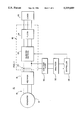
In FIG. 1, an inverter system 10 includes a generator 12 which may be, for example, driven by a variable speed prime mover such as the turbine engine of an aircraft. The generator 12 has a three phase output 14 which, if the generator 12 is driven by a variable speed prime mover, carries wild frequency AC power. A rectifier 16 rectifies the wild frequency AC power on the three phase output 14 of the generator 12 into DC power and supplies this DC power to an inverter 18.
The inverter 18 includes a DC link 20 which receives the DC power from the output of the rectifier 16. Inverter switches 22 of the inverter 18 switch the DC power on the DC link 20 in order to produce AC power. Typically, the inverter switches 22 are controlled in a manner to chop the DC power on the DC link 20 into pulse width modulated pulses which are filtered by a filter 24 to produce three phase, sinusoidal AC power for supply to AC loads 26. The filter 24 is normally arranged to eliminate higher order harmonics in the three phase AC power provided by the inverter 22. Since filters capable of filtering the lower order harmonics (e.g., the third and the fifth harmonics) are massive and expensive, the inverter switches 22 are typically controlled in such a fashion that they suppress those lower order harmonics other than the first harmonic.
The inverter switches 22 are controlled by a controller 28. Harmonics in an inverter signal, i.e. those frequencies which are integer multiples (e.g., 1, 2, 3, 4, 5, . . . ) of the fundamental frequency of the inverter 18, are sensed by a bandpass filter 30 and an analyzer 32. As shown in FIG. 1, the inverter signal is the DC power on the DC link 20 which contains, not only the DC from the rectifier 16, but also any harmonics of the inverter fundamental frequency which feed back through the inverter switches 22 from the output of the inverter 18 to the DC link 20. Accordingly, the bandpass filter 30 is connected to the DC link 20.
The lower cutoff frequency of the bandpass filter 30 is selected to eliminate the DC component on the DC link from the output of the bandpass filter 30. The upper cutoff frequency of the bandpass filter 30 depends upon the harmonics to be controlled by the controller 28. For example, if the filter 34 eliminates all harmonics above the 50th harmonic, the inverter controller 28 controls the inverter switches 22 so as to control all harmonics in the output of the inverter 18 up to and including the 50th harmonic. Thus, the bandpass filter 30 must pass all harmonics up to and including the 50th harmonic to the controller 28. These, controlled harmonics of the inverter fundamental frequency are supplied by the bandpass filter 30 to the analyzer 32. The analyzer 32 determines the magnitudes and phases of the harmonics of the inverter fundamental frequency which are present on the DC link 20. With this arrangement, the harmonics in the output of the inverter 18 are controlled based upon the harmonics on the DC link 20.
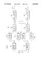
One embodiment of the analyzer 32 is shown in more detail in FIG. 2. As shown in FIG. 2, the analyzer 32 includes a first sampler 36 which samples the output of the bandpass filter 30 at a sampling frequency to produce a first sample set Amn. A second sampler 38 samples the output of the bandpass filter 30 at the same sampling frequency to produce a second sample set Bmn. The samples in the second sample set Bmn are displaced in phase by 90° from corresponding samples in the first sample set Amn. The harmonic components in the DC signal on the DC link 20 can be determined from these two sample sets.
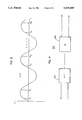
The phase relationship between corresponding samples in the first and second sample sets Amn and Bmn can be seen more clearly from FIG. 3. In the output of the bandpass filter 30 are the harmonics of interest one of which, i.e. the signal fn (t), is shown in FIG. 3. The sampling frequency for the signal fn (t) is mnf where f is the fundamental frequency of the output of the inverter 18, n is the harmonic number of the signal fn (t), nf is the frequency of the signal fn (t), and m is an integer which is selected according to the desired sampling frequency. The first sampler 36 of the analyzer 32 produces the first sample set Amn, which includes the samples A1, A2, . . . , Ak. The second sampler 38 of the analyzer 32 produces the second sample set Bmn, which includes the samples B1, B2, . . . ,Bk. Although the samples in the first sample set Amn may be taken at any phase of the signal fn (t), the samples in the second sample set Bmn are taken so that each sample Bk is separated in phase by 90° from its corresponding sample Ak. Thus, as shown in FIG. 3, the sample B1 occurs 90° in phase after its corresponding sample A1, the sample B2 occurs 90° in phase after its corresponding sample A2, . . . , and the sample Bk occurs 90° in phase after its corresponding sample Ak.
The samples in the first and second sample sets Amn and Bmn are used to determine the magnitude and phase of the signal fn (t) by vector analysis. Thus, if m=1, the sampling frequency nf is the frequency nf of the harmonic n and the magnitude of the signal fn (t) can be determined by the following equation: ##EQU3## where magn is the magnitude of the signal fn (t), a is the sum of all of the samples Ak in the first sample set Amn, b is the sum of all of the samples Bk in the second sample set Bmn, and k=1, 2, 3 . . . k. Similarly, the phase of the signal fn (t) can be determined by the following equation: ##EQU4## where phan is the phase of the signal fn (t), a is the sum of all of the samples Ak in the first sample set Amn, b is the sum of all of the samples Bk in the second sample set Bmn, and k=1, 2, 3 . . . k. Alternatively, a and b in equations (4) and (5) may be computed as the averages of the samples in the corresponding sample sets Amn and Bmn. Using the averages of the samples in the corresponding sets Amn, and Bmn normalizes the quantity magn.
Since the controller 28 controls the inverter 22 at a known fundamental frequency, any harmonics which may appear at the input of the inverter 18 also have known frequencies. Such harmonics may be caused, for example, by operation of the inverter 18. Thus, the output of the bandpass filter 30 is sampled at each of the frequencies of the harmonics to be suppressed. If it is desired to suppress the 13th harmonic of the inverter fundamental frequency, for example, the output of the bandpass filter 30 is also sampled at a sampling frequency equal to the frequency of the 13th harmonic. If it is also desired to suppress the 15th harmonic of the inverter fundamental frequency, the output of the bandpass filter 30 is sampled at a sampling frequency equal to the frequency of the 15th harmonic. These corresponding sample sets are then used in the above equations to determine the magnitude and phase of each of the harmonics of interest, i.e. of the 13th harmonic and the 15th harmonic in the above example. Based upon the magnitude and phase of each of the harmonics of interest, the controller 28 controls the inverter switches 22 in any known fashion so as to suppress all but the first harmonic from the output of the inverter 18.
However, it is likely that harmonics having frequencies which are integer multiples of the harmonic frequency of interest will also appear on the DC link 20 of the inverter 18. Therefore, sampling at the frequency of the harmonic of interest produces results which are influenced by any integer multiples of the harmonic of interest if such integer multiples of the harmonic of interest are present in the analyzed signal. For example, let it be assumed that the signal being analyzed has a fundamental frequency f, that n1 is the harmonic number of the harmonic of interest, that n2 is the harmonic number of a harmonic of both the harmonic n1 of interest and the fundamental frequency (i.e., n2 is an integer multiple of n1), that both the harmonic n1 and the harmonic n2 are present in the signal being analyzed, and that no harmonics having a harmonic number greater than n2 are present in the signal being analyzed. If the signal being sampled is sampled at a sampling frequency n2 f, i.e. the frequency of the harmonic n2, and if a sufficient number of the samples are summed, the resulting sum is substantially dependent only upon the harmonic n2 and will not contain any significant portion dependent upon lower order harmonics. That is, because of the periodic nature of harmonics, the portion in each sample resulting from lower order harmonics will sum to zero. Thus, when the samples are summed, the resulting sum is dependent only upon the harmonic n2.
However, if the signal is sampled at a sampling frequency n1 f, i.e. the frequency of the harmonic n1, and if the samples are summed, the sum includes not only a portion dependent upon the harmonic n1 but, also, a portion dependent upon higher order harmonics, such as the harmonic n2. Consequently, if the signal is sampled at the sampling frequency n2 f, if all of the resulting samples are summed to produce a first sum, if a sufficient number of the samples related to the frequency n1 f of the harmonic n1 are summed to produce a second sum, and if the average of the first sum is subtracted from the average of the second sum, the result is a quantity dependent primarily upon the harmonic n1, and has no significant portion dependent upon the harmonic n2.
Averages are used here for normalization purposes. That is, the number of samples at the n2 f sampling frequency is necessarily greater than the number of samples at the n1 f sampling frequency. Therefore, without normalization, the difference between the sum of the n2 f samples and the sum of the n1 f samples would be influenced more by the n2 f samples than by the n1 f samples. To even out these influences, the sum of the n2 f samples and the sum of the n1 f samples are normalized by using the average of the n2 f samples and the average of the n1 f samples.
As a specific example, if the 13th harmonic is a harmonic of interest to be suppressed by the proper control of the inverter switches 22, and if it is assumed that the filter 24 adequately eliminates all harmonics above the 50th harmonic, then the additional harmonics which might influence the sum of the samples resulting from a sampling frequency equal to the frequency of the 13th harmonic are the 26th and the 39th harmonics. Thus, a sampling frequency equal to the frequency of the 78th harmonic is chosen to produce each of the sample sets Amn and Bmn. Every second sample in the sample set Amn are summed to produce a first sum, i.e. a sum dependent upon the 39th harmonic. Every third sample in the sample set are summed to produce a second sum, i.e. a sum dependent upon the 26th harmonic. Every sixth sample is used to produce a third sum, i.e. a sum dependent upon the 13th, 26th, and the 39th harmonics. After normalization (i.e., averaging), the first and second sums are subtracted from the third sum to produce a quantity dependent only upon the 13th harmonic. A sampling frequency equal to the 78th harmonic is chosen instead of a sampling frequency equal to the 39th harmonic because the 26th harmonic can be derived from the 78th (by summing every third sample) but not from the 39th harmonic.
As shown in FIG. 2, the sampler 36 produces a sample set Amn where n is the harmonic number of the harmonic of interest (e.g., n1), and m is an integer multiple of the harmonic of interest and is selected to include one or more multiples of the harmonic of interest which may also appear in the signal being analyzed (e.g., m is selected so that mn=n2). In the example above, n is the harmonic number related to the 13th harmonic and m is 6 indicating that the sampling frequency should be the frequency of the 78th harmonic. At this sampling frequency, the samples in the sample set Amn include samples of the 13th, the 26th, and the 39th harmonics. Likewise, the samples included in the sample set Bmn include samples of the 13th, the 26th, and the 39th harmonics.
Averagers 42 . . . 44 average all the appropriate samples of the sample set Amn by summing all of the appropriate samples and dividing by the number of samples in the sum. In the example above, every second sample of the sample set Amn relating to the 39th harmonic are averaged, every third sample of the sample set Amn relating to the 26th harmonic are averaged, and every sixth sample of the sample set Amn relating to the 13th harmonic are averaged. Similarly, averagers 46 . . . 48 average all of the appropriate samples of the sample set Bmn by summing all of the appropriate samples and dividing by the number of samples in the sum. Thus, every second sample of the sample set Bmn relating to the 39th harmonic are averaged, every third sample of the sample set Bmn relating to the 26th harmonic are averaged, and every sixth sample of the sample set Bmn relating to the 13th harmonic are averaged.
A subtractor 50 subtracts the appropriate averages produced by the averagers 42 . . . 44 from the average related to the harmonic of interest. Thus, in the example above, the average related to the 39th harmonic in the sample set Amn and the average related to the 26th harmonic in the sample set Amn are subtracted from the average related to the 13th harmonic in the sample set Amn. Accordingly, with respect to the first sample set Amn, the influence of the harmonics which are integer multiples of the harmonic of interest, i.e. the 26th and the 39th harmonics in the above example, are removed from the average of the samples related to the harmonic of interest, i.e. the 13th harmonic in the above example. What remains is an average of the first sample set Amn dependent only upon the harmonic of interest.
Similarly, a subtractor 52 subtracts the appropriate averages produced by the averagers 46 . . . 48 from the average related to the harmonic of interest. Thus, in the example above, the average related to the 39th harmonic in the sample set Bmn and the average related to the 26th harmonic in the sample set Bmn are subtracted from the average related to the 13th harmonic in the sample set Bmn. Accordingly, with respect to the second sample set Bmn, the influence of the harmonics which are integer multiples of the harmonic of interest, i.e. the 26th and the 39th harmonics in the above example, are removed from the average of the samples related to the harmonic of interest, i.e. the 13th harmonic in the above example. What remains is an average of the second sample set Bmn dependent only upon the harmonic of interest.
A square root extractor 54 determines the magnitude of the harmonic of interest according to the following equation: ##EQU5## where magn is the magnitude of the harmonic of interest having the harmonic number n, a is the difference determined by the subtractor 50, and b is the difference determined by the subtractor 52. The quantity magn is supplied to the controller 28 shown in FIG. 1 over an output 56 of the square root extractor 54. A trigonometric extractor 58 determines the phase of the harmonic of interest according to the following equation: ##EQU6## where phan is the phase of the harmonic of interest having the harmonic number n, a is the difference determined by the subtractor 50, and b is the difference determined by the subtractor 52. The quantity phan is supplied to the controller 28 shown in FIG. 1 over an output 60 of the trigonometric extractor 58. With the magnitude and the phase of the harmonic of interest now known, the controller 28 can apply any known control methodology (such as that disclosed in the Kirchberg et al. U.S. Pat. No. 5,053,939) in order to control the inverter switches 22 to eliminate the effect of the harmonic n1 of interest from the output of the inverter switches 22.
Equations (6) and (7) may be used, together with samples taken at the appropriate sampling frequencies, to determine the phase and magnitude of each harmonic to be controlled. Thus, the first harmonic, i.e. the harmonic at the fundamental frequency, may be controlled at a desired phase and magnitude based upon the measured phase and magnitude of the first harmonic as determined by equations (6) and (7), and the other harmonics may be controlled based upon the measured corresponding phases and magnitudes as determined by equations (6) and (7) so that the effects of these other harmonics are suppressed from the output of the inverter switches 22.
In selecting an appropriate sampling frequency for all of the harmonics of interest, the lowest frequency common to all of these harmonies of interest, and to all of the multiples of these harmonics which may be present, is chosen. For example, if only the 11th and 13th harmonics are of interest (i.e., are to be controlled), and if the filter 24 suppresses all harmonics above the 50th harmonic, the 22nd, 26th, 33rd, 39th, and 44th harmonics (i.e., which are integer multiples of the 11th and 13th harmonics) may also be present, and their effects must be eliminated from the samples of their corresponding harmonics of interest. The lowest frequency common to all of these harmonics is the frequency of the 1716th harmonic. Thus, the frequency of the 1716th harmonic is chosen as the sampling frequency.
However, it is likely that more harmonics than just the 11th and the 13th harmonics are to be controlled. As the number of harmonics to be controlled increases, the lowest common harmonic increases dramatically, and may become too high to be practicable. A lower, yet still high, sampling frequency may be chosen such that, although the sampling frequency is not common to all harmonics of interest and their integer multiples, the error associated with using samples that are not at exactly the frequency of one or more of these harmonics is low. Alternatively, separate sampling frequencies may be used for each harmonic to be controlled. Thus, in the example above where the 11th and 13th harmonics are to be controlled, a sampling frequency of the 132th harmonic is used for the 11th harmonic because it is common to the 11th, 26nd, the 33rd, and the 44th harmonics (i.e., it is common to the harmonic of interest and each of its integer multiples up to the harmonic not filtered by the filter 24), and an additional sampling frequency of the 78th harmonic is used for the 13th harmonic because it is common to the 13th, the 26th, and the 39th harmonics (i.e., it is common to the harmonic of interest and each of its integer multiples up to the harmonic not filtered by the filter 24).
While it may be desirable to control the inverter switches 22 so as to eliminate a large number of harmonics, many control methodologies do not permit the control of a large number of harmonics. Thus, it may be possible to suppress the 13th harmonic but not the 26th and 39th harmonics even though samples related to these harmonics have been obtained. For example, in the system disclosed by Kirchberg, et al. in the U.S. Pat. No. 4,994,956, the switching angles of PWM pulses produced by the inverter switches of an inverter are adjusted in accordance with the measured harmonics in order to control the harmonic content in the output of the inverter. Because the number of switching angles are finite, the number of harmonics which can be so controlled is also finite. Thus, while it may be desirable to control the harmonic n1, e.g. the 13th harmonic, and its integer multiples n2, n3, . . . , e.g. the 26th and 39th harmonics, it may only be practicable to control the harmonic n1, e.g. the 13th harmonic, and it may not be practicable to control its integer multiples n2, n3, . . . , e.g. the 26th and 39th harmonics.
As indicated above, the samplers 36 and 38 sample at a sampling frequency which is high enough to include not only the harmonic of interest but also any integer multiples of the harmonic of interest if those integer multiples of the harmonic of interest may appear in the signal being analyzed. There should be a sufficient number of averagers to average all of the relevant sets of samples in the Amn set of samples. The number of averagers depends upon the number of harmonics of interest and the number of integer multiples which may be present. For example, if the harmonic n1 of interest is the 7th harmonic of the inverter fundamental frequency, the harmonics which are integer multiples of the 7th harmonic, i.e. the 14th harmonic, the 21st harmonic, the 28th harmonic, the 35th harmonic, the 42nd harmonic, and the 49th harmonic may also be present in the signal, it being understood, as discussed above, that the filter 24 adequately suppresses all harmonics above the 50th harmonic. Accordingly, the samplers 36 and 38 should be arranged to sample the output of the bandpass filter 30 at a sampling frequency high enough to include samples for each of these harmonics. A sufficient number of averagers are necessary to average all samples in the sample set Amn related to each of these harmonics. Similarly, there should be a sufficient number of averagers to average all samples in the relevant sets of samples in the Bmn set of samples.
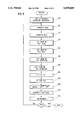
FIG. 4 shows another embodiment for the analyzer 32 shown in FIG. 1. In the embodiment shown in FIG. 4, the analyzer 32' includes an analog to digital (A-to-D) converter 62 which converts the output from the bandpass filter 30 to a digital signal. A microprocessor 64 samples the digital signal from the A-to-D converter 62 and determines the magnitude and phase of the harmonic components of the signal on the DC link 20. The microprocessor 64 operates according to the flow chart shown in FIG. 5.
When the program 66 shown in FIG. 5 is entered, a block 68 first sets a variable n to the frequency of the highest order harmonic to be controlled. A block 70 samples the output from the A-to-D converter 62 at a sampling frequency mnf where n is set by the block 68, m is an integer selected so that the sampling frequency produces samples of the harmonic n and each of the integer multiples of the harmonic n which may be present in the digital signal from the A-to-D converter 62, and f is the fundamental frequency of the inverter 18. Thus, the sampling frequency mnf is the lowest frequency common to the harmonic n and each of the integer multiples of the harmonic n which may be present. For example, if n=13 to indicate the 13th harmonic, and if the 39th harmonic is the highest order harmonic multiple of the 13th harmonic which may be present in the digital signal from the A-to-D converter 62, then m is set to a value of 6. The block 70 accordingly produces a sample set Amn.
A block 72 then samples, at the same sampling frequency, the output of the A-to-D converter 62 to produce a second sample set Bmn, wherein each sample of the sample set Bmn is displaced in phase by 90° from a corresponding sample in the sample set Amn. A block 74 determines the averages of the samples relating to each of the integer multiples of the harmonic n in the sample set Amn and sums these averages, and a block 76 determines the averages of the samples relating to each of the integer multiples of the harmonic n in the sample set Bmn and sums these averages. A block 78 determines the average of the samples relating to the harmonic n, and a block 80 determines the average of the samples relating to the harmonic n in the sample set Bmn.
A block 82 subtracts the sum produced by the block 74 from the average produced by the block 78. Similarly, a block 84 subtracts the sum produced by the block 76 from the average produced by the block 80. A block 86 determines the magnitude of the harmonic n of interest by extracting the square root of the sum of the squares of the differences determined by the blocks 82 and 84 and sends that magnitude to the controller 28. A block 88 determines the phase of the harmonic n of interest by extracting the arc tangent of the difference determined by the block 84 divided by the difference determined by the block 82 and sends that phase to the controller 28.
A block 90 decrements n to the harmonic number of the next lower harmonic to be controlled. A block 92 then determines whether the magnitude and phase of all harmonics to be controlled have been determined. If not, the magnitude and phase of the next harmonic of interest are determined by the blocks 70-88. When all harmonics of interest have been processed, the program ends.
Rather than starting over with a complete new set of samples each time the harmonics in the inverter signal are to be determined, the analyzer 32/32' may add the newest pair of samples (or a predetermined number of pairs of samples) to the corresponding sample sets Amn and Bmn, drop out the oldest pair of samples (or the oldest predetermined number of pairs of samples), and recompute the magnitude and phase of each harmonic to be controlled during each pass through the program of FIG. 5.
Furthermore, the analyzer 32 is shown in FIG. 1 as analyzing an inverter signal in the form of the DC power on the DC link 20, i.e. the analyzer 32 is shown analyzing the output from the bandpass filter 30 which is connected to the DC link 20. Alternatively, the inverter signal may be the constant frequency AC power at a POR (Point of Reference) 94 (FIG. 1) between the filter 24 and the AC loads 26. In this case, a bandpass filter would not be necessary; however, each phase of the inverter 18 output must be analyzed. Accordingly, instead of determining the harmonics in the output of the inverter 18 based upon a single analysis of the harmonics on the DC link 20, three analyses are required to analyze directly the harmonics in the output of the inverter 18. Thus, while analyzing the AC power at the POR 94 provides a more direct measure of the harmonic content in the AC power being supplied to the AC loads 26, the signal processing power is tripled.
Various other modifications and adaptations may be made by those skilled in the art without departing from the scope and spirit of the invention. Therefore, the present invention is to limited only by the following claims.

Claims (26)

We claim:
1. An apparatus for determining a frequency component of a signal comprising:
sampling means for sampling the signal at a sampling frequency, wherein the sampling means produces first and second sets of samples at the sampling frequency, and wherein corresponding samples of the first and second sets of samples are separated in phase by substantially 90°; and,
frequency component determining means for determining the frequency component of the signal from the first and second sets of samples.
2. The apparatus of claim 1 wherein the frequency component determining means comprises phase and magnitude determining means for determining phase and magnitude of the frequency component from the first and second sets of samples.
3. The apparatus of claim 2 wherein the phase and magnitude determining means comprises first sample summing means for summing the first set of samples to determine a first sum, second sample summing means for summing the second set of samples to determine a second sum, and means for determining the magnitude and phase of the frequency component based upon the first and second sums.
4. The apparatus of claim 3 wherein the phase and magnitude determining means comprises magnitude determining means for determining the magnitude of the frequency component according to the following equation: ##EQU7## where mag is the magnitude of the frequency component, a is based upon the first sum, and b is based upon the second sum, and wherein the phase and magnitude determining means further comprises phase determining means for determining the phase of the frequency component according to the following equation: ##EQU8## where pha is the phase of the frequency component, a is based upon the first sum, and b is based upon the second sum.
5. The apparatus of claim 2 wherein the phase and magnitude determining means comprises magnitude determining means for determining the magnitude of the frequency component according to the following equation: ##EQU9## where mag is the magnitude of the frequency component, a is a normalized value relating to the first set of samples, and b is a normalized value relating to the second set of samples, and wherein the phase and magnitude determining means further comprises phase determining means for determining the phase of the frequency component according to the following equation: ##EQU10## where pha is the phase of the frequency component, a is a normalized value relating to the first set of samples, and b is a normalized value relating to the second set of samples.
6. An apparatus for determining a first harmonic component of a signal, wherein the signal has a fundamental frequency f, wherein the first harmonic component has a frequency n1 f, wherein n1 is an integer, wherein the signal has a second harmonic component, wherein the second harmonic component has a frequency n2 f, and wherein n2 is an integer multiple of n1, the apparatus comprising:
sampling means for sampling the signal at a sampling frequency n3 f, wherein the sampling means produces first and second sets of samples at the sampling frequency n3 f, wherein n3 is an integer multiple of n1, and wherein corresponding samples in the first and second sets of samples are separated in phase by substantially 90°; and,
harmonic component determining means for determining the first harmonic component from the first and second sets of samples.
7. The apparatus of claim 6 wherein the harmonic component determining means comprises phase and magnitude determining means for determining phase and magnitude of the first harmonic component based upon the first and second sets of samples.
8. The apparatus of claim 7 wherein the phase and magnitude determining means comprises first sample summing means for summing samples of the first set of samples related to the frequency n1 f to determine a first sum, second sample summing means for summing samples of the first set of samples related to the frequency n2 f to determine a second sum, third sample summing means for summing samples of the second set of samples related to the frequency n1 f to determine a third sum, fourth sample summing means for summing samples of the second set of samples related to the frequency n2 f to determine a fourth sum, and means for determining the magnitude and phase of the first harmonic component based upon the first, second, third, and fourth sums.
9. The apparatus of claim 8 wherein the phase and magnitude determining means comprises magnitude determining means for determining the magnitude of the first harmonic component according to the following equation: ##EQU11## where magn1 is the magnitude of the first harmonic component, a is related to the first sum less the second sum, and b is related to the third sum less the fourth sum, and wherein the phase and magnitude determining means further comprises phase determining means for determining the phase of the first harmonic component according to the following equation: ##EQU12## where phan1 is the phase of the first harmonic component, a is related to the first sum less the second sum, and b is related to the third sum less the fourth sum.
10. The apparatus of claim 7 wherein the phase and magnitude determining means comprises magnitude determining means for determining the magnitude of the first harmonic component according to the following equation: ##EQU13## where magn1 is the magnitude of the first harmonic component, a is an average of the samples in the first set of samples related to the frequency n1 f less an average of the samples in the first set of samples related to the frequency n2 f, and b is an average of the samples in the second set of samples related to the frequency n1 f less an average of the samples in the second set of samples related to the frequency n2 f, and wherein the phase and magnitude determining means further comprises phase determining means for determining the phase of the first harmonic component according to the following equation: ##EQU14## where phan1 is the phase of the first harmonic component, a is an average of the samples in the first set of samples related to the frequency n1 f less an average of the samples in the first set of samples related to the frequency n2 f, and b is an average of the samples in the second set of samples related to the frequency n1 f less an average of the samples in the second set of samples related to the frequency n2 f.
11. The apparatus of claim 6 wherein n3 is an integer multiple of n2 and wherein n2 and n3 are unequal.
12. An inverter system comprising:
an inverter having a DC receiving means for receiving input DC power and AC providing means for providing output AC power having a fundamental frequency f;
harmonic determining means connected to the inverter for sampling a signal of the inverter at a sampling frequency n2 f to produce first and second sets of samples and for determining a harmonic of the fundamental frequency f from the first and second sets of samples, wherein the harmonic has a frequency n1 f, wherein corresponding samples in the first and second sets of samples are separated in phase by substantially 90°, wherein n2 is an integer greater than n1, and wherein the frequency n2 f is another harmonic of the fundamental frequency f; and,
controlling means connected to the inverter and to the harmonic determining means for controlling the inverter so as to suppress the harmonic having the frequency n1 f.
13. The apparatus of claim 12 wherein the harmonic determining means determines phase and magnitude of the harmonic having the frequency n1 f from the first and second sets of samples.
14. The apparatus of claim 13 wherein the harmonic determining means sums the samples of the first set of samples related to the frequency n1 f to determine a first sum, sums the samples of the first set of samples related to a frequency of a harmonic which is an integer multiple of the harmonic having frequency n1 f to determine a second sum, sums the samples of the second set of samples related to the frequency n1 f to determine a third sum, sums the samples of the second set of samples related to the frequency of the harmonic which is an integer multiple of the harmonic having frequency n1 f to determine a fourth sum, and determines the magnitude and phase of the harmonic having the frequency n1 f based upon the first, second, third, and fourth sums.
15. The apparatus of claim 14 wherein the harmonic determining means determines the magnitude of the harmonic having the frequency n1 f according to the following equation: ##EQU15## where magn1 is the magnitude of the harmonic having the frequency n1 f, a is related to the first sum less the second sum, and b is related to the third sum less the fourth sum, and determines the phase of the harmonic having the frequency n1 f according to the following equation: ##EQU16## where phan1 is the phase of the harmonic having the frequency n1 f, a is related to the first sum less the second sum, and b is related to the third sum less the fourth sum.
16. The apparatus of claim 13 wherein the harmonic determining means determines the magnitude of the harmonic having the frequency n1 f according to the following equation: ##EQU17## where magn1 is the magnitude of the harmonic having the frequency n1 f, a is an average of the samples in the first set of samples related to the frequency n1 f less an average of the samples in the first set of samples related to a harmonic which is an integer multiple of the harmonic having the frequency n1 f, and b is an average of the samples in the second set of samples related to the frequency n1 f less an average of the samples in the second set of samples related to the harmonic which is an integer multiple of the harmonic having the frequency n1 f, and wherein the harmonic determining means further determines the phase of the harmonic having the frequency n1 f according to the following equation: ##EQU18## where phan1 is the magnitude of the harmonic having the frequency n1 f, a is an average of the samples in the first set of samples related to the frequency n1 f less an average of the samples in the first set of samples related to the harmonic which is an integer multiple of the harmonic having the frequency n1 f, and b is an average of the samples in the second set of samples related to the frequency nf less an average of the samples in the second set of samples related to the harmonic which is an integer multiple of the harmonic having the n1 f.
17. An inverter system comprising:
an inverter having a DC receiving means for receiving input DC power and AC providing means for providing output AC power having a fundamental frequency f;
harmonic determining means connected to the inverter for sampling a signal of the inverter at a sampling frequency to produce first and second sets of samples and for determining a harmonic of the fundamental frequency f from the first and second sets of samples, wherein the harmonic has a frequency n1 f, and,
controlling means connected to the inverter and to the harmonic determining means for controlling the inverter so as to suppress the harmonic having the frequency n1 f.
18. The apparatus of claim 17 wherein the harmonic determining means comprises phase and magnitude determining means for determining phase and magnitude of the harmonic having the frequency n1 f from the first and second sets of samples.
19. The apparatus of claim 18 wherein the phase and magnitude determining means comprises first sample summing means for summing the samples of the first set of samples related to the frequency n1 f to determine a first sum, second sample summing means for summing the samples of the first set of samples related to a frequency n2 f to determine a second sum, wherein n2 is an integer multiple of n1, third sample summing means for summing the samples of the second set of samples related to the frequency n1 f to determine a third sum, fourth sample summing means for summing the samples of the second set of samples related to the frequency n2 f to determine a fourth sum, and means for determining the magnitude and phase of the harmonic having the frequency n1 f based upon the first, second, third, and fourth sums.
20. The apparatus of claim 19 wherein the phase and magnitude determining means comprises magnitude determining means for determining the magnitude of the harmonic having the frequency n1 f according to the following equation: ##EQU19## where magn1 is the magnitude of the harmonic having the frequency n1 f, a is related to the first sum less the second sum, and b is related to the third sum less the fourth sum, and wherein the phase and magnitude determining means further comprises phase determining means for determining the phase of the harmonic having the frequency n1 f according to the following equation: ##EQU20## phan1 is the phase of the harmonic having the frequency n1 f, a is related to the first sum less the second sum, and b is related to the third sum less the fourth sum.
21. The apparatus of claim 18 wherein n2 is an integer multiple of n1, wherein the phase and magnitude determining means comprises magnitude determining means for determining the magnitude of the harmonic having the frequency n1 f according to the following equation: ##EQU21## where magn1 is the magnitude of the harmonic having the frequency n1 f, a is an average of the samples in the first set of samples related to the frequency n1 f less an average of the samples in the first set of samples related to a frequency n2 f, and b is an average of the samples in the second set of samples related to the frequency n1 f less an average of the samples in the second set of samples related to the frequency n2 f, and wherein the phase and magnitude determining means further comprises phase determining means for determining the phase of the harmonic having the frequency n1 f according to the following equation: ##EQU22## where phan1 is the phase of the harmonic having the frequency n1 f, a is an average of the samples in the first set of samples related to the frequency n1 f less an average of the samples in the first set of samples related to the frequency n2 f, and b is an average of the samples in the second set of samples related to the frequency n1 f less an average of the samples in the second set of samples related to the frequency n2 f.
22. A method for determining a component in a signal, wherein the signal has a fundamental frequency f, and wherein the component has a frequency n1 f which is substantially an integer multiple of the fundamental frequency f, the method comprising to following steps:
sampling the signal at a sampling frequency to produce first and second sets of samples, wherein corresponding samples in the first and second sets of samples are separated in phase by substantially 90°; and,
determining the component from the first and second sets of samples.
23. The method of claim 22 wherein the step of sampling the signal comprises the step of determining phase and magnitude of the component from the first and second sets of samples.
24. The method of claim 23 wherein a frequency n2 f is substantially an integer multiple of the frequency n1 f, wherein the step of determining phase and magnitude comprises the steps of summing samples of the first set of samples related to the frequency n1 f to determine a first sum, summing samples of the first set of samples related to the frequency n2 f to determine a second sum, summing samples of the second set of samples related to the frequency n1 f to determine a third sum, summing samples of the second set of samples related to the frequency n2 f to determine a fourth sum, and determining the magnitude and phase of the component based upon the first, second, third, and fourth sums.
25. The method of claim 24 wherein the step of determining phase and magnitude comprises the further steps of determining the magnitude of the component according to the following equation: ##EQU23## where mag is the magnitude of the component, a is related to the first sum less the second sum, and b is related to the third sum less the fourth sum, and determining the phase of the component according to the following equation: ##EQU24## where pha is the phase of the component, a is related to the first sum less the second sum, and b is related to the third sum less the fourth sum.
26. The method of claim 23 wherein a frequency n2 f is substantially an integer multiple of the frequency n1 f, wherein the step of determining phase and magnitude comprises the further steps of determining the magnitude of the component according to the following equation: ##EQU25## where mag is the magnitude of the component, a is an average of the samples in the first set of samples related to the frequency n1 f less an average of the samples in the first set of samples related to the frequency n2 f, and b is an average of the samples in the second set of samples related to the frequency n1 f less an average of the samples in the second set of samples related to the frequency n2 f, and determining the phase of the component according to the following equation: ##EQU26## where pha is the phase of the component, a is an average of the samples in the first set of samples related to the frequency n1 f less an average of the samples in the first set of samples related to the frequency n2 f, and b is an average of the samples in the second set of samples related to the frequency n1 f less an average of the samples in the second set of samples related to the frequency n2 f.
US08/287,326 1994-08-08 1994-08-08 Harmonic content determination apparatus Expired - Fee Related US5559689A (en)

Priority Applications (1)

Application Number Priority Date Filing Date Title
US08/287,326 US5559689A (en) 1994-08-08 1994-08-08 Harmonic content determination apparatus

Applications Claiming Priority (1)

Application Number Priority Date Filing Date Title
US08/287,326 US5559689A (en) 1994-08-08 1994-08-08 Harmonic content determination apparatus

Publications (1)

Publication Number Publication Date
US5559689A true US5559689A (en) 1996-09-24

Family

ID=23102417

Family Applications (1)

Application Number Title Priority Date Filing Date
US08/287,326 Expired - Fee Related US5559689A (en) 1994-08-08 1994-08-08 Harmonic content determination apparatus

Country Status (1)

Country Link
US (1) US5559689A (en)

Cited By (23)

* Cited by examiner, † Cited by third party
Publication number Priority date Publication date Assignee Title
US5721689A (en) * 1995-12-18 1998-02-24 Abb Power T&D Company Inc. System and method for phasor estimation and frequency tracking in digital protection systems
US6141227A (en) * 1999-06-03 2000-10-31 Cheltenham Induction Heating Limited Of Phoenix Works Power supply with reduced second harmonic
US6185482B1 (en) 1998-03-10 2001-02-06 Abb Power T&D Company Inc. System and method for rms overcurrent backup function
US6282104B1 (en) * 2000-03-14 2001-08-28 Applied Power Corporation DC injection and even harmonics control system
US6395027B1 (en) 2000-04-25 2002-05-28 The Penn State Research Foundation Artificial heart with arrhythmia signalling
US6451055B1 (en) 2000-04-25 2002-09-17 The Penn State Research Foundation Artificial heart data communication system
US6458164B1 (en) 2000-04-25 2002-10-01 The Penn State Research Foundation Artificial heart with energy recovery
US6478820B1 (en) 2000-04-25 2002-11-12 The Penn State Research Foundation Artificial heart with synchronous rectification
US6570779B2 (en) * 2001-10-04 2003-05-27 Kokusan Denki Co., Ltd. Pulse with modulation inverter generation using a correction co-efficient and a reference to the ratio to obtain a real duty ratio
US6579315B1 (en) 2000-04-25 2003-06-17 The Penn State Research Foundation Artificial heart power supply system
US20040066162A1 (en) * 2002-09-26 2004-04-08 3M Innovative Properties Company Adaptable spatial notch filter
US20040080164A1 (en) * 2001-12-07 2004-04-29 Mckelvey Terence Turbine generator starting method and turbine generation system
US20140347069A1 (en) * 2013-05-24 2014-11-27 Det International Holding Limited Arc detection
US20160241036A1 (en) * 2012-09-27 2016-08-18 James F. Wolter Energy apparatuses, energy systems, and energy management methods including energy storage
RU2611256C1 (en) * 2015-12-18 2017-02-21 Федеральное государственное бюджетное учреждение науки Институт проблем управления им. В.А. Трапезникова Российской академии наук Method of measuring vectors of harmonic signals with constant component
US20170117716A1 (en) * 2011-09-29 2017-04-27 James F. Wolter Power generation systems with integrated renewable energy generation, energy storage, and power control
US9855376B2 (en) 2014-07-25 2018-01-02 Minnetronix, Inc. Power scaling
US10003186B2 (en) * 2016-06-15 2018-06-19 Hamilton Sundstrand Corporation Variable-speed constant-frequency power control
US10149933B2 (en) 2014-07-25 2018-12-11 Minnetronix, Inc. Coil parameters and control
CN109240195A (en) * 2018-10-19 2019-01-18 江苏方天电力技术有限公司 Oil immersed type converter transformer cooling system control method and control system
US10193395B2 (en) 2015-04-14 2019-01-29 Minnetronix, Inc. Repeater resonator
US10342908B2 (en) 2015-01-14 2019-07-09 Minnetronix, Inc. Distributed transformer
US10406267B2 (en) 2015-01-16 2019-09-10 Minnetronix, Inc. Data communication in a transcutaneous energy transfer system

Citations (7)

* Cited by examiner, † Cited by third party
Publication number Priority date Publication date Assignee Title
US4961130A (en) * 1989-12-11 1990-10-02 Sundstrand Corporation Voltage inverter control applying real-time angle pattern determination
US4977492A (en) * 1990-04-25 1990-12-11 Sundstrand Corporation Suppression of switching harmonics
US4994956A (en) * 1990-04-25 1991-02-19 Sundstrand Corporation Enhanced real time control of PWM inverters
US5001622A (en) * 1990-05-10 1991-03-19 Sundstrand Corporation Enhanced real-time control of PWM inverter
US5034876A (en) * 1990-09-10 1991-07-23 Sundstrand Corporation Real-time evaluation of PWM inverter pattern selection
US5043857A (en) * 1990-04-11 1991-08-27 Sundstrand Corporation Real-time control of PWM inverters by pattern development from stored constants
US5053939A (en) * 1990-08-27 1991-10-01 Sundstrand Corporation Control of PWM inverters by pattern development from stored constants relating D.C. link harmonics to output distortion

Patent Citations (7)

* Cited by examiner, † Cited by third party
Publication number Priority date Publication date Assignee Title
US4961130A (en) * 1989-12-11 1990-10-02 Sundstrand Corporation Voltage inverter control applying real-time angle pattern determination
US5043857A (en) * 1990-04-11 1991-08-27 Sundstrand Corporation Real-time control of PWM inverters by pattern development from stored constants
US4977492A (en) * 1990-04-25 1990-12-11 Sundstrand Corporation Suppression of switching harmonics
US4994956A (en) * 1990-04-25 1991-02-19 Sundstrand Corporation Enhanced real time control of PWM inverters
US5001622A (en) * 1990-05-10 1991-03-19 Sundstrand Corporation Enhanced real-time control of PWM inverter
US5053939A (en) * 1990-08-27 1991-10-01 Sundstrand Corporation Control of PWM inverters by pattern development from stored constants relating D.C. link harmonics to output distortion
US5034876A (en) * 1990-09-10 1991-07-23 Sundstrand Corporation Real-time evaluation of PWM inverter pattern selection

Cited By (33)

* Cited by examiner, † Cited by third party
Publication number Priority date Publication date Assignee Title
US5721689A (en) * 1995-12-18 1998-02-24 Abb Power T&D Company Inc. System and method for phasor estimation and frequency tracking in digital protection systems
US6185482B1 (en) 1998-03-10 2001-02-06 Abb Power T&D Company Inc. System and method for rms overcurrent backup function
US6141227A (en) * 1999-06-03 2000-10-31 Cheltenham Induction Heating Limited Of Phoenix Works Power supply with reduced second harmonic
US6282104B1 (en) * 2000-03-14 2001-08-28 Applied Power Corporation DC injection and even harmonics control system
US6579315B1 (en) 2000-04-25 2003-06-17 The Penn State Research Foundation Artificial heart power supply system
US6395027B1 (en) 2000-04-25 2002-05-28 The Penn State Research Foundation Artificial heart with arrhythmia signalling
US6451055B1 (en) 2000-04-25 2002-09-17 The Penn State Research Foundation Artificial heart data communication system
US6458164B1 (en) 2000-04-25 2002-10-01 The Penn State Research Foundation Artificial heart with energy recovery
US6478820B1 (en) 2000-04-25 2002-11-12 The Penn State Research Foundation Artificial heart with synchronous rectification
US6570779B2 (en) * 2001-10-04 2003-05-27 Kokusan Denki Co., Ltd. Pulse with modulation inverter generation using a correction co-efficient and a reference to the ratio to obtain a real duty ratio
US20040080164A1 (en) * 2001-12-07 2004-04-29 Mckelvey Terence Turbine generator starting method and turbine generation system
US6847129B2 (en) * 2001-12-07 2005-01-25 Ebara Corporation Turbine generator starting method and turbine generation system
US20040066162A1 (en) * 2002-09-26 2004-04-08 3M Innovative Properties Company Adaptable spatial notch filter
WO2004029634A2 (en) * 2002-09-26 2004-04-08 3M Innovative Properties Company Adaptable spatial notch filter
WO2004029634A3 (en) * 2002-09-26 2004-07-08 3M Innovative Properties Co Adaptable spatial notch filter
US6963184B2 (en) 2002-09-26 2005-11-08 3M Innovative Properties Company Adaptable spatial notch filter
US20170117716A1 (en) * 2011-09-29 2017-04-27 James F. Wolter Power generation systems with integrated renewable energy generation, energy storage, and power control
US20160241036A1 (en) * 2012-09-27 2016-08-18 James F. Wolter Energy apparatuses, energy systems, and energy management methods including energy storage
US20140347069A1 (en) * 2013-05-24 2014-11-27 Det International Holding Limited Arc detection
US9739821B2 (en) * 2013-05-24 2017-08-22 Det International Holding Limited Arc detection
US9855376B2 (en) 2014-07-25 2018-01-02 Minnetronix, Inc. Power scaling
US10149933B2 (en) 2014-07-25 2018-12-11 Minnetronix, Inc. Coil parameters and control
US10898628B2 (en) 2014-07-25 2021-01-26 Minnetronix, Inc. Coil parameters and control
US10376625B2 (en) 2014-07-25 2019-08-13 Minnetronix, Inc. Power scaling
US11207516B2 (en) 2015-01-14 2021-12-28 Minnetronix, Inc. Distributed transformer
US10342908B2 (en) 2015-01-14 2019-07-09 Minnetronix, Inc. Distributed transformer
US10406267B2 (en) 2015-01-16 2019-09-10 Minnetronix, Inc. Data communication in a transcutaneous energy transfer system
US11235141B2 (en) 2015-01-16 2022-02-01 Minnetronix, Inc. Data communication in a transcutaneous energy transfer system
US10193395B2 (en) 2015-04-14 2019-01-29 Minnetronix, Inc. Repeater resonator
US11894695B2 (en) 2015-04-14 2024-02-06 Minnetronix, Inc. Repeater resonator
RU2611256C1 (en) * 2015-12-18 2017-02-21 Федеральное государственное бюджетное учреждение науки Институт проблем управления им. В.А. Трапезникова Российской академии наук Method of measuring vectors of harmonic signals with constant component
US10003186B2 (en) * 2016-06-15 2018-06-19 Hamilton Sundstrand Corporation Variable-speed constant-frequency power control
CN109240195A (en) * 2018-10-19 2019-01-18 江苏方天电力技术有限公司 Oil immersed type converter transformer cooling system control method and control system

Similar Documents

Publication Publication Date Title
US5559689A (en) Harmonic content determination apparatus
US5671112A (en) Digital integrator V/Hz relay for generator and transformer over-excitation protection
US5805395A (en) Half-cycle summation V/Hz relay for generator and transformer over-excitation protection
US5514978A (en) Stator turn fault detector for AC motor
US5567994A (en) Active harmonic filter with time domain analysis
US4878185A (en) Digital measuring instrument
US5673196A (en) Vector electricity meters and associated vector electricity metering methods
US5488281A (en) Method and apparatus for predicting winding failure using zero crossing times
Ferrah et al. Sensorless speed detection of inverter fed induction motors using rotor slot harmonics and fast Fourier transform
US6507184B1 (en) Methods and apparatus for differential current measurement in a three-phase power system
US20040186669A1 (en) System and method for exact compensation of fundamental phasors
EP0708339A2 (en) Data collection and processing for digital AC power system monitor/analyzer
US4500837A (en) Detection of DC content in an AC waveform
EP0599648A1 (en) Three-phase power analyzer
CA2668132C (en) Stray flux processing method and system
US6081768A (en) Digital peak detector
US4556842A (en) Tracking filter for sensing DC content in an AC waveform
EP0638811A2 (en) Estimator of amplitude and frequency of a noisy biased sinusoid from short bursts of samples
US6046895A (en) Distance protection method
CA2344645A1 (en) Method and device for determining the torque of an induction machine
SE417883B (en) SET AND DEVICE FOR DETECTING THE SPEED OF AN ASYNCHRON MOTOR MOTOR
D'Apuzzo et al. A time-domain approach for the analysis of nonstationary signals in power systems
RU2621880C1 (en) Device for determining rotation speed of induction motor rotors
Ferrah et al. An investigation into speed measurement of induction motor drives using rotor slot harmonics and spectral estimation techniques
EP1026509B1 (en) Method and apparatus for determining harmonics in electric network

Legal Events

Date Code Title Description
AS Assignment

Owner name: SUNDSTRAND CORPORATION, ILLINOIS

Free format text: ASSIGNMENT OF ASSIGNORS INTEREST;ASSIGNORS:KIRCHBERG, MAURICE;COOK, ALEC;REEL/FRAME:007116/0215

Effective date: 19940804

FEPP Fee payment procedure

Free format text: PAYOR NUMBER ASSIGNED (ORIGINAL EVENT CODE: ASPN); ENTITY STATUS OF PATENT OWNER: LARGE ENTITY

FPAY Fee payment

Year of fee payment: 4

FPAY Fee payment

Year of fee payment: 8

FEPP Fee payment procedure

Free format text: PAYOR NUMBER ASSIGNED (ORIGINAL EVENT CODE: ASPN); ENTITY STATUS OF PATENT OWNER: LARGE ENTITY

Free format text: PAYER NUMBER DE-ASSIGNED (ORIGINAL EVENT CODE: RMPN); ENTITY STATUS OF PATENT OWNER: LARGE ENTITY

REMI Maintenance fee reminder mailed
LAPS Lapse for failure to pay maintenance fees
STCH Information on status: patent discontinuation

Free format text: PATENT EXPIRED DUE TO NONPAYMENT OF MAINTENANCE FEES UNDER 37 CFR 1.362

FP Lapsed due to failure to pay maintenance fee

Effective date: 20080924