US5566269A - Strain relieving holder for optical fiber cable - Google Patents
Strain relieving holder for optical fiber cable Download PDFInfo
- Publication number
- US5566269A US5566269A US08/453,303 US45330395A US5566269A US 5566269 A US5566269 A US 5566269A US 45330395 A US45330395 A US 45330395A US 5566269 A US5566269 A US 5566269A
- Authority
- US
- United States
- Prior art keywords
- channels
- holder
- bottom member
- cable
- set forth
- Prior art date
- Legal status (The legal status is an assumption and is not a legal conclusion. Google has not performed a legal analysis and makes no representation as to the accuracy of the status listed.)
- Expired - Lifetime
Links
Images


Classifications
-
- G—PHYSICS
- G02—OPTICS
- G02B—OPTICAL ELEMENTS, SYSTEMS OR APPARATUS
- G02B6/00—Light guides; Structural details of arrangements comprising light guides and other optical elements, e.g. couplings
- G02B6/44—Mechanical structures for providing tensile strength and external protection for fibres, e.g. optical transmission cables
- G02B6/4439—Auxiliary devices
- G02B6/4471—Terminating devices ; Cable clamps
Definitions
- the present invention relates to the field of optical fiber interconnection and more particularly to strain relief members for optical fiber cable.
- a plurality of pairs of associated optical fibers are to be interconnected and such interconnections must thereafter be held securely and carefully, usually in an organizer tray or cassette within a larger enclosure or cabinet, and usually in an array of such trays or cassettes.
- Such trays must also hold generous portions of the fibers adjacent the interconnections, or splices, to permit splice repair without requiring cable replacement.
- the trays or cassettes also provide for securing jacketed portions of the cables containing one or more of the optical fibers, at ends of the trays.
- the splice connections comprise fusion of the ends or end lengths of the associated optical fibers, or adhesive bonding, or precision clamping, and the thus-fused fiber ends are preferably maintained within a protective sleeve or adapter to maintain the precision alignment of the fibers and provide a level of strain relief to the coupling.
- strain relief member for clamping of multifiber fiber optic ribbon cable to define strain relief therefor.
- the present invention comprises at least a bottom member of resilient material when strain relief of only jacketed fiber optic cable is desired, and may be an assembly of the bottom member and a top member or cap of resilient material, when strain relief of smaller diameter buffered fiber or ribbon cable is desired.
- the strain relief bottom member is placeable at either end of an organizer or tray or at the cable exit of a cassette and may be affixed to the bottom tray wall such as by adhesive or double sided tape.
- the bottom member includes an array of generally parallel channels or grooves formed into and along the top surface, separated by elongate protrusions, and having constrictions along the entrances thereinto; slots of only incremental width extend from the top surface into and along each protrusion at its center and into which may be placed small diameter buffered fiber and ribbon cable, with the resilient material of the bottom member being deformable when the ribbon cable or buffered fiber of slightly greater width is urged into the slot, the slot side walls thereafter slightly compress against the ribbon cable or buffered fiber after insertion.
- the channels are dimensioned to receive relatively large diameter (e.g., 3 mm) jacketed cable, with the constrictions being less wide than such cable to retain the cable in the channels after placement especially after the top member is affixed to the bottom member; the slots provide for temporary widening of the constrictions during placement of the jacketed cables into the channels, by permitting outward deflection of the portions of the protrusions; and no top member is necessary when only jacketed cable is involved.
- relatively large diameter e.g., 3 mm
- a top member of resilient material that includes a corresponding array of parallel elongate lugs extending below and along a bottom surface thereof to become inserted into associated ones of the channels of the bottom member, and including undercuts complementary to the constrictions of the channels to securely hold the lugs within the associated channels and thus hold the top member securely to the bottom member without other fasteners and also permitting removal of the top member when desired.
- a top member may be used that has a lug severed from the top member at each position opposing each channel holding a jacketed fiber.
- bottom and top members of resilient material of slightly different configuration are used together for both jacketed fiber optic cable and also buffered fiber and ribbon cable.
- a bottom member includes protrusions defining channels with constrictions as before and also includes small width slots extending downwardly into the top surface in the center of the protrusions, into which buffered fiber or ribbon cable may be inserted.
- a top member includes elongate lugs with undercuts to be snapped into the channels of the bottom member and when positioned will close off the small width slots containing any buffered fibers or ribbon cable.
- the jacketed cable is insertable along respective top member channels by being pressed through the narrower constrictions which then secure the cables in the channels in a manner not requiring a further top member to close off the entrances to the channels.
- bottom and top members of resilient material of slightly different configuration are used for both jacketed fiber optic cable and also buffered fiber and ribbon cable.
- the bottom member includes an array of larger dimensioned channels separated by protrusions having slots thereinto of incremental width, and buffered fiber and ribbon cable are insertable into the slots of the bottom member.
- Into the top surface of the top member are slits of only incremental width extending toward the bottom surface at each of the lug locations and parallel thereto, extending to cylindrical passageways of selected diameter extending along and within the lugs.
- a jacketed cable is insertable downwardly through and along a respective slit of the top member and into the passageway, whereafter the top member is allowed to resile and hold the inserted cable under slight compression.
- Assured retention results from the top member being assembled to the bottom member as the constrictions interfit with the lug undercuts to retain the lugs therein and maintain the top member's slits assuredly closed, keeping all jacketed cable in the passageways.
- the bottom member's channels may have a generally rectangular shape in cross-section or may be more of a dovetail shape, while the top member's lug cross-section may be cylindrical for either channel cross-section shape.
- strain relief member that is adapted to receive either conventional fiber optic cable, buffered fiber or ribbon cable as desired.
- strain relief member of the present invention may be fastened to each other without discrete fasteners, and are easily detachable from and refastenable to each other.
- FIG. 1 is a plan view of a splice tray having cable strain relief members of the present invention at ends thereof and a splice holder centrally disposed therebetween;
- FIGS. 2 to 6 are elevation, isometric and cross-section views of the strain relief members of FIG. 1 showing representative jacketed fiber cable, buffered fiber and ribbon cable inserted thereinto;
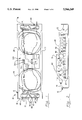
- FIG. 7 is an alternate embodiment of the strain relief members of the present invention.
- FIGS. 8 to 10 are further alternate embodiments of the strain relief members of the present invention, with FIGS. 9 and 10 being cross-section views showing different style channel cross-sections of the bottom member;
- FIG. 11 is an isometric view of the splice holder of FIG. 1, with a representative single-fiber splice, a representative ribbon cable splice and a representative passive device held therein;
- FIG. 12 is a cross-section view of the splice holder of FIG. 11 showing a discrete buffered fiber, a ribbon cable and a passive device both being held in and being inserted into respective slits thereof.
- a splice tray or organizer 10 includes a tray body 12 having a bottom wall 14, opposed ends 16,18 and opposed side walls 20,22, as well as a preferably transparent cover member (not shown) that is securable to tray body 12.
- a splice holder 300 (see FIGS. 11 and 12) is affixed to bottom wall 14 generally centrally positioned between ends 16,18 within which splice connections of pairs of associated optical fibers of single-fiber cables, or splice connections of arrays of fibers of associated ribbon cables, or passive devices joining two fiber optic members or two pairs of fiber optic members, may be positioned.
- Tray 10 provides substantial fiber-holding space between the ends for generous loops of discrete fibers 26 after being broken out from jacketed cables to be disposed, that would be held in tray 10 by the cover member placed thereover, with the loops being either large loops extending the length of the tray between the ends and passing by the sides of splice holder 300, or being smaller and being disposed between an end and splice holder 300.
- each strain relief holder 40 includes a unitary bottom member 42 and may include, as shown, a pair of top members 44,46.
- Bottom member 42 includes a plurality of generally parallel elongate channels 48 formed into and along top surface 50 extending between first and second ends 52,54, with elongate protrusions 56 positioned between adjacent channels 48.
- a central region 58 devoid of channels is shown that includes a vertical hole 60 through which may extend a vertical rod (not shown) of an enclosure for stacking of a plurality of splice trays.
- Splice holder 300 is shown to include a similar hole for like purpose.
- Channels 48 are dimensioned to receive thereinto, if desired, jacketed portions of fiber optic cables 28 (as shown in FIG. 4) that have for example diameters of 3 mm, and each is undercut to form retention ledges 62 near top surface 50 defining therebetween a constriction less wide than the cable that will hold a jacketed cable 28 in position once inserted, without need for top members 44,46.
- entrances to channels 48 include chamfers 64 to facilitate initial stages of cable insertion. It is preferred that the channels 48 be slightly less wide than the diameter of cable 28 to slightly press against the cable jacket.
- Each protrusion 56 preferably has a narrow slot 66 formed thereinto from top surface 50, with narrow slot 66 being dimensioned to approximately equal the thickness of a ribbon cable to receive thereinto a ribbon cable 32 as shown in FIG. 3.
- FIGS. 5 and 6 illustrate the placement of a buffered fiber 26 into a slot 66, if desired. Slots 66 also can assist in insertion of jacketed cables 28 into channels 48 by allowing upper portions of protrusions 56 to be flexed outwardly when a cable 28 is urged into the slightly narrower entrance to a channel 48 above retention ledges 62.
- top members 44,46 are used that self-fasten to bottom member 42, as shown in FIGS. 2, 3, 5 and 6.
- Elongate lugs 68 extend along and downwardly from bottom surface 70 of each top member 44,46 dimensioned to be fit into associated channels 48 of bottom member 42.
- Undercuts 72 near the base of each lug 68 cooperate with retention ledges 62 at the entrances to channels 48 for affixing top members 44,46 to bottom member 42.
- Also facilitating insertion of lugs 68 into channels 48 are chamfered edges 74; similarly, facilitating withdrawal of lugs 68 from channels 48 during top member removal, are chamfered edges 76 at undercuts 72.
- top members 44 and 46 are separately attachable and removable, and include lift tabs 78,80 respectively that are offset from each other atop central region 58 of bottom member 42.
- Lift tabs 78,80 preferably extend beyond first and second ends 52,54 respectively of bottom member 42 facilitating manual engagement, and they also define between themselves a clearance around hole 60 for a stacking rod extending through hole 60.
- Top members 44,46 may also be utilized where a mixture of jacketed cable 28 and either ribbon cable 32 or buffered cable 26 is desired to be used; at each location where a jacketed cable 28 is to be disposed in a channel 48, the corresponding lug 68 is removed from the top member such as by being snipped away.
- strain relief holders 40 may be utilized within the splice tray if desired, positioned on both sides of a splice coupler site to hold adjacent portions of buffered fiber or ribbon cable.
- strain relief holders may be utilized independently of a splice tray per se, for similar purposes, with the bottom surface of the bottom member affixed to a surface such as by adhesive, and with the top member, if used, snapped onto the bottom member and self-retaining thereon without other fasteners in a manner permitting removal if desired.
- the top member may be made for example of a thermoplastic resin such as RTP154 non-reinforced flame retardant polypropylene sold by RTP Company, Winona, Minn.
- the bottom member may be made for example of a thermoplastic rubber such as SANIPRENE elastomer having Part No. 25180 sold by Advanced Elastomer Systems, St. Louis, Mo.
- the top and bottom members preferably are individually molded; optionally, however, they may be extruded since all features (save hole 60 and lift tabs 78,80) are selected to provide the members with continuous cross-sections therealong, and the remaining features may easily be defined by simple secondary operations.
- Elastomeric material is preferred for bottom member 42 so that the side walls of channels 48 slightly narrower than jacketed fiber can be deformed outwardly generating compression with the jacketed cable while minimizing any possibility of compressing the fiber therewithin, and so that side walls of slots 66 slightly narrower than buffered fiber or ribbon cable can be deformed outwardly generating compression with the buffered fiber or ribbon cable without compressing the fiber or fibers. It is preferred that the slots be about 0.0015 inches wide to accommodate either ribbon cable or buffered fiber.
- strain relief holder assembly 100 is shown in FIG. 7, wherein bottom member 102 has channels 104 separated by split protrusions 106 that are generally cylindrical in cross-section, with narrow constrictions at the upper entrances serving to retain fiber optic cables 26 therein. Small width slots 108 are formed into protrusions 106, into which are insertable buffered fiber or ribbon cable.
- Top member 110 includes elongate lugs 112 generally cylindrical in cross-section to be snapped into corresponding channels 104, to interlock top member 110 with bottom member 102.
- Top member 110 also includes positioned between the locations of lugs 112 grooves 114 cylindrical in cross-section for receipt thereinto of jacketed cable, and the entrances to grooves 114 from top surface 116 are constrictions 118 slightly narrower than the diameter of the jacketed cable, to retain the cable in the grooves 114 once inserted. Both top and bottom members are utilized together for jacketed cable, buffered cable or ribbon cable.
- the top and bottom members 102,110 of strain relief assembly 100 may be extruded of thermoplastic material such as for example, polypropylene and SANIPRENE rubber as with the embodiment of FIGS. 1 to 6.
- FIGS. 8 and 9 is shown an additional embodiment of strain relief holder assembly 200 having a bottom member 202 and a top member 204.
- Bottom member 202 includes parallel elongate channels 206 formed into top surface 208, separated by elongate protrusions 210, with protrusions 210 being split by incremental width slits 212.
- Top member 204 provides elongate lugs 214 depending from bottom surface 216 and dimensioned to be received past the constrictions at entrances to channels 206 and be held therein.
- Incremental width slits 218 are formed into top surface 220 of top member 204 coincident with the lug locations, extending into respective lugs 214 to conclude in cylindrical passageways 222.
- Jacketed cable is to be held in top member 204 by being inserted downwardly through slits 218 into passageways 222, and passageways 222 are also capable of holding fusion couplings of spliced fibers so that assembly 200 may also be used as a splice holder.
- Ribbon cable such as 32, as well as discrete buffered fiber, is to be held in bottom member 202 by being inserted downwardly into slits 212.
- the interlockable top and bottom members serve to cooperate with each other to hold any of the fiber optic members described, and are also separable to repair or replace the fiber optic members.
- Channels 206 are shown to be of a dovetail cross-section with angled side walls converging at the upper entrance to define a constriction less wide than the diameter of the lugs 214 which are shown to be cylindrical or bulbous in cross-section.
- FIG. 10 a strain relief holder assembly 250 having a top member 252 similar to top member 204 of FIGS. 8 and 9.
- Bottom member 254 is shown to have channels 256 of cylindrical cross-section complementary to and interlockable with lugs 258 having cylindrical cross-section.
- slits 260 are formed in the protrusions separating channels 256, and slits 262 of top member 252 extend to passageways 264 located within and along lugs 258, enabling assembly 250 to be utilized in similar fashion to assembly 200.
- a variety of shapes may be devised of cross-sections of the channels of the bottom member and the lugs of the top member, that are appropriately interlockable with the channels and preferably permit separation and relocking of the top and bottom members when desired.
- FIGS. 11 and 12 illustrate the splice holder 300 of FIG. 1, a generally thick planar member of elastomeric material having opposed ends 302,304 and opposed side edges 306,308 dimensioned to be placed into splice tray 10 between side walls 20,22 and usually centrally disposed between tray ends (FIG. 1).
- Splice holder 300 may be easily mounted onto bottom wall 14 of splice tray 10 such as by adhesive or cement, and may utilize double sided tape and also peelable transfer paper.
- Each splice holder 300 may be as disclosed in U.S. patent application Ser. No. 08/453,730, pending, filed May 30, 1995.
- Slits 310 are cut into top surface 312 of splice holder 300 to extend toward bottom surface 314, parallel to opposed side edges 306,308, with a central holder portion 316 remaining free of slits enabling splice tray 10 to be stacked with others thereof onto a vertical rod to extend central hole 318.
- Large apertures 320 are formed adjacent the middle of portion 316 of splice holder 300 to intersect slits 310.
- splice connections 24,30 of discrete fibers 26 and ribbon cables 32 are disposed in large apertures 320, with portions of fibers 26 and cables 32 extending therefrom through respective slits 310 to be held therein.
- Large apertures 320 facilitate manual gripping of splice connections 24,28 for repair and servicing if desired, and slits 310 permit easy removal from the splice holder and easy replacement thereinto.
- slits 310 may have essentially no width.
- the elastomeric material of splice holder 300 is a microcellular foam elastomeric material such as PORON high density microcellular open celled urethane, Product No. 4701-01, sold by Poron Materials Division of Rogers Corporation of East Woodstock, Conn.
- a fiber or ribbon cable or passive device is urged downwardly into a slit 310 with walls thereof being urged outwardly permitting the fiber or ribbon cable to be moved into the slit.
- the walls resume their original abutting position above the fiber or the ribbon cable and generate a limited amount of compressive engagement with the fiber or ribbon cable or passive device, insufficient to cause any deformation thereto but enough to frictionally engage the fiber or ribbon cable or passive device to secure it in position.
- strain relieving holder of the present invention may also be used independently of a splice tray if desired by simply being secured to a selected surface in a desired orientation to receive and hold fiber optic members such as jacketed fiber optic cable, discrete buffered optical fiber or ribbon cable. Variations and modifications may occur to others that are within the spirit of the invention and the scope of the claims.
Abstract
Description
Claims (18)
Priority Applications (1)
| Application Number | Priority Date | Filing Date | Title |
|---|---|---|---|
| US08/453,303 US5566269A (en) | 1995-05-30 | 1995-05-30 | Strain relieving holder for optical fiber cable |
Applications Claiming Priority (1)
| Application Number | Priority Date | Filing Date | Title |
|---|---|---|---|
| US08/453,303 US5566269A (en) | 1995-05-30 | 1995-05-30 | Strain relieving holder for optical fiber cable |
Publications (1)
| Publication Number | Publication Date |
|---|---|
| US5566269A true US5566269A (en) | 1996-10-15 |
Family
ID=23800009
Family Applications (1)
| Application Number | Title | Priority Date | Filing Date |
|---|---|---|---|
| US08/453,303 Expired - Lifetime US5566269A (en) | 1995-05-30 | 1995-05-30 | Strain relieving holder for optical fiber cable |
Country Status (1)
| Country | Link |
|---|---|
| US (1) | US5566269A (en) |
Cited By (54)
| Publication number | Priority date | Publication date | Assignee | Title |
|---|---|---|---|---|
| US5850494A (en) * | 1996-06-27 | 1998-12-15 | O'dell; Dennis R. | Fiber sequence and clarification aiding device |
| US6195496B1 (en) * | 1999-07-30 | 2001-02-27 | Lucent Technologies, Inc. | Splice holder with tilted mounting feature |
| US6226439B1 (en) * | 1999-07-30 | 2001-05-01 | Lucent Technologies, Inc. | Splice holder with self locking feature |
| US6249636B1 (en) * | 1999-09-07 | 2001-06-19 | Lucent Technologies, Inc. | High density fusion splice holder |
| US6259851B1 (en) * | 1999-09-17 | 2001-07-10 | Lucent Technologies Inc. | High density fiber splice holder |
| US6285815B1 (en) * | 1999-09-07 | 2001-09-04 | Lucent Technologies Inc. | High density fusion splice holder |
| US6332052B1 (en) * | 2000-02-28 | 2001-12-18 | Corning Cable Systems Llc | Optical fiber ribbon cables with controlled bending behavior |
| GB2369196A (en) * | 2000-11-15 | 2002-05-22 | Marconi Optical Components Ltd | Optical circuit housing containing resiliently deformable material or oval former |
| US6442323B1 (en) * | 2001-01-05 | 2002-08-27 | Us Conec Ltd. | Flexible optical circuit having a protective foam layer |
| US6496638B1 (en) * | 1998-10-23 | 2002-12-17 | Lucent Technologies Inc. | Optical fiber cassette |
| US6512179B1 (en) | 2001-09-28 | 2003-01-28 | International Business Machines Corporation | Transmission cable strain relief device |
| WO2003026996A1 (en) * | 2001-09-21 | 2003-04-03 | Corning Incorporated | Apparatus and method for holding coilable elongated product |
| US6580867B2 (en) * | 2000-07-13 | 2003-06-17 | Alcatel | Support for small-diameter filamentary elements and a bundle of filamentary elements held together by the support |
| US6620105B2 (en) * | 2000-12-07 | 2003-09-16 | Gary L. Sharpe | Device for organizing multiple leads |
| US20030175000A1 (en) * | 2002-03-14 | 2003-09-18 | Caracci Stephen J. | Fiber and lens grippers, optical devices and methods of manufacture |
| US6640042B2 (en) * | 1998-09-01 | 2003-10-28 | Fujitsu Limited | Optical fiber holder |
| US20030228122A1 (en) * | 2002-06-10 | 2003-12-11 | Frank Loh | Device holder accommodating wavelength division multiplexers |
| US6687450B1 (en) * | 2000-05-15 | 2004-02-03 | Tyco Electronics Raychem Nv | Break-out device |
| US6694084B1 (en) * | 2000-06-23 | 2004-02-17 | Mitsubishi Denki Kabushiki Kaisha | Optical cable excess handling unit and optical cable wiring method |
| US20040071431A1 (en) * | 2001-03-12 | 2004-04-15 | Denis Trouchet | Guide for passing optical fibers and receiving housing for optical components fitted with one such guide |
| US6801704B1 (en) * | 2003-05-30 | 2004-10-05 | Lucent Technologies Inc. | Fiber optics splice holder |
| US20040240831A1 (en) * | 2001-10-03 | 2004-12-02 | Armando Loni | Mounting of optical components |
| US20050106948A1 (en) * | 2003-11-13 | 2005-05-19 | Yuan-Huei Peng | Cable manager |
| US6939165B1 (en) * | 2004-07-22 | 2005-09-06 | Hon Hai Precision Ind. Co., Ltd. | Cable connector assembly with cable holder |
| US6944383B1 (en) | 2004-04-12 | 2005-09-13 | Adc Telecommunications, Inc. | Cable management panel with sliding drawer and methods |
| US20060171075A1 (en) * | 2005-01-18 | 2006-08-03 | Panduit Corp. | Cable management support bar with strain relief clamps |
| US20060279187A1 (en) * | 2005-06-10 | 2006-12-14 | Central Industrial Supply Company | Detent pin bearing retainer lock for a drawer slide |
| US20070292085A1 (en) * | 2006-06-19 | 2007-12-20 | Nielson Jeffrey D | Non-halogen fiber optic connectors |
| US20080025685A1 (en) * | 2006-07-25 | 2008-01-31 | Airbus Deutschland Gmbh | Holder for optical fibres |
| US7400815B2 (en) | 2004-03-08 | 2008-07-15 | Adc Telecommunications, Inc. | Fiber access terminal |
| US7418186B1 (en) | 2007-05-11 | 2008-08-26 | Preformed Line Products Company | Fiber retention sleeve |
| US20090067804A1 (en) * | 2006-04-11 | 2009-03-12 | Jens Knorr | Splitting Apparatus and Manipulating Apparatus for Optical Waveguides |
| US7512304B2 (en) | 2007-03-23 | 2009-03-31 | Adc Telecommunications, Inc. | Drop terminal with anchor block for retaining a stub cable |
| US20090190891A1 (en) * | 2008-01-25 | 2009-07-30 | Fujifilm Corporation | Optical fiber structure |
| US20100080512A1 (en) * | 2008-09-05 | 2010-04-01 | Chris Taylor | Patch panel assembly |
| US7844158B2 (en) | 2007-10-09 | 2010-11-30 | Adc Telecommunications, Inc. | Mini drop terminal |
| WO2011020743A1 (en) * | 2009-08-17 | 2011-02-24 | Tyco Electronics Amp Gmbh | Connection device for an optical fibre |
| US7903923B2 (en) | 2007-10-09 | 2011-03-08 | Adc Telecommunications, Inc. | Drop terminal releasable engagement mechanism |
| US20110147542A1 (en) * | 2009-12-07 | 2011-06-23 | Ross Matthew Hoek | Cable organizer |
| US20120032036A1 (en) * | 2009-02-04 | 2012-02-09 | Roxtec Ab | Pipe or cable lead-through blocks |
| EP2482108A1 (en) | 2011-01-31 | 2012-08-01 | Tyco Electronics Raychem BVBA | Cable plug assembly |
| US20130108220A1 (en) * | 2011-10-31 | 2013-05-02 | Marco Antonio Gonzalez Garcia | Systems and methods for providing a ferrule boot |
| DE102012006870A1 (en) * | 2012-04-04 | 2013-10-10 | Wilhelm Rutenbeck Gmbh & Co. Kg | Connector for mechanical butt joint of light guides, has clamping portion that is provided with clamping jaws that are formed in parallel on both sides of insertion path for clamping ends of light guides |
| US8622481B2 (en) | 2011-01-25 | 2014-01-07 | Joy Mm Delaware, Inc. | Fiber optic cable protection in a mining system |
| US20140233894A1 (en) * | 2013-02-21 | 2014-08-21 | Avago Technologies General Ip (Singapore) Pte. Ltd. | User-configurable optical fiber link |
| JP2015169729A (en) * | 2014-03-05 | 2015-09-28 | スリーエム イノベイティブ プロパティズ カンパニー | Cable holding structure and optical fiber connector |
| US9293862B2 (en) | 2013-08-26 | 2016-03-22 | Panduit Corp. | Patch cord plug organizer |
| US9698529B1 (en) * | 2013-02-28 | 2017-07-04 | Amazon Technologies, Inc. | Cable holder for system serviceabilty |
| US20180259738A1 (en) * | 2012-10-31 | 2018-09-13 | Commscope Technologies Llc | Anchoring cables to rack with cable clamp arrangements |
| WO2019072782A1 (en) * | 2017-10-09 | 2019-04-18 | CommScope Connectivity Belgium BVBA | Cable fixation devices and methods |
| WO2019114462A1 (en) * | 2017-12-14 | 2019-06-20 | 江苏亨通光电股份有限公司 | Bulit-in wire sorting box device of optical fiber tank |
| US20190363527A1 (en) * | 2018-05-24 | 2019-11-28 | Beijing Apollo Ding rong Solar Technology Co., Ltd | Cable collecting device, cable guiding device and building component |
| US20230014214A1 (en) * | 2018-05-14 | 2023-01-19 | Afl Telecommunications Llc | Butt closures and organizer assemblies therefor |
| WO2023200812A1 (en) * | 2022-04-11 | 2023-10-19 | Ppc Broadband, Inc. | Adapter configured to permit a heat shrink splice holder portion of a fiber splice cassette to hold a mechanical crimp splice protector |
Citations (29)
| Publication number | Priority date | Publication date | Assignee | Title |
|---|---|---|---|---|
| US3768146A (en) * | 1972-02-22 | 1973-10-30 | Bell Telephone Labor Inc | Method of splicing optical fibers |
| US4627686A (en) * | 1984-08-10 | 1986-12-09 | Siecor Corporation | Splicing tray for optical fibers |
| US4687289A (en) * | 1985-09-17 | 1987-08-18 | Brintec Corporation | Fiberoptic splice organizer |
| US4688886A (en) * | 1984-08-30 | 1987-08-25 | Siemens Aktiengesellschaft | Device for holding two light waveguides connected to one another by a splice |
| US4702551A (en) * | 1984-10-11 | 1987-10-27 | Reliance Comm/Tec Corporation | Method and apparatus for handling and storing cabled spliced ends of fiber optics |
| US4793681A (en) * | 1988-04-18 | 1988-12-27 | Gte Products Corporation | Splice cradle |
| US4840449A (en) * | 1988-01-27 | 1989-06-20 | American Telephone And Telegraph Company, At&T Bell Laboratories | Optical fiber splice organizer |
| US4842362A (en) * | 1982-09-14 | 1989-06-27 | Gte Products Corporation | Housing for a fiber optic splice |
| US4854661A (en) * | 1987-11-05 | 1989-08-08 | Gte Products Corporation | Splice cradle |
| US4911521A (en) * | 1988-03-15 | 1990-03-27 | Sumitomo Electric Industries, Ltd. | Connecting box for multi-optical fiber cable |
| US5005941A (en) * | 1989-09-05 | 1991-04-09 | Gte Products Corporation | Fiber optic splice assembly |
| US5044719A (en) * | 1989-08-11 | 1991-09-03 | Amp Incorporated | Cable connector |
| US5046811A (en) * | 1989-07-17 | 1991-09-10 | Jung Roger E | Junction box for optical communications cords, and gland assembly for cord |
| US5069523A (en) * | 1988-12-08 | 1991-12-03 | Siemens Aktiengesellschaft | Cassette for spare lengths of light waveguides to be used at the site to be spliced |
| US5071211A (en) * | 1988-12-20 | 1991-12-10 | Northern Telecom Limited | Connector holders and distribution frame and connector holder assemblies for optical cable |
| US5125057A (en) * | 1989-11-20 | 1992-06-23 | At&T Bell Laboratories | Optical fiber splicing device |
| US5133039A (en) * | 1990-10-29 | 1992-07-21 | At&T Bell Laboratories | Aerial fiber optic cable case |
| US5146532A (en) * | 1990-11-20 | 1992-09-08 | Scientific-Atlanta, Inc. | Optical fiber retention device |
| US5208893A (en) * | 1992-05-21 | 1993-05-04 | Raynet Corporation | Optical fiber splice tray and splice holder |
| US5222184A (en) * | 1989-10-10 | 1993-06-22 | Bowthorpe-Hellermann Limited | Optical fibre splice storage tray |
| US5278933A (en) * | 1992-06-30 | 1994-01-11 | Hunsinger Terrance D | Fiber optic splice organizer and associated method |
| US5337390A (en) * | 1992-04-21 | 1994-08-09 | Minnesota Mining And Manufacturing Company | Adhesiveless connector for optical fibers |
| US5375185A (en) * | 1993-04-30 | 1994-12-20 | Keptel, Inc. | Apparatus for storing and organizing spliced optical fibers |
| US5416882A (en) * | 1992-11-25 | 1995-05-16 | Mars Actel | Device for positioning and retaining optical fibers in a layer |
| US5420956A (en) * | 1993-01-28 | 1995-05-30 | Krone Aktiengesellschaft | Case for passive optical components |
| US5422974A (en) * | 1994-09-23 | 1995-06-06 | The United States Of America As Represented By The Secretary Of The Navy | Shock resistant optic fiber rotary splice holding device |
| US5471555A (en) * | 1994-11-21 | 1995-11-28 | Sumitomo Electric Lightwave Corp. | Fiber optic ribbon break-out device with enhanced strain relief |
| US5474178A (en) * | 1994-06-23 | 1995-12-12 | Molex Incorporated | Packaging tray for electrical connectors |
| US5499314A (en) * | 1994-11-22 | 1996-03-12 | Leite; Sara M. | Shock resistant optic fiber rotary splice holding device |
-
1995
- 1995-05-30 US US08/453,303 patent/US5566269A/en not_active Expired - Lifetime
Patent Citations (29)
| Publication number | Priority date | Publication date | Assignee | Title |
|---|---|---|---|---|
| US3768146A (en) * | 1972-02-22 | 1973-10-30 | Bell Telephone Labor Inc | Method of splicing optical fibers |
| US4842362A (en) * | 1982-09-14 | 1989-06-27 | Gte Products Corporation | Housing for a fiber optic splice |
| US4627686A (en) * | 1984-08-10 | 1986-12-09 | Siecor Corporation | Splicing tray for optical fibers |
| US4688886A (en) * | 1984-08-30 | 1987-08-25 | Siemens Aktiengesellschaft | Device for holding two light waveguides connected to one another by a splice |
| US4702551A (en) * | 1984-10-11 | 1987-10-27 | Reliance Comm/Tec Corporation | Method and apparatus for handling and storing cabled spliced ends of fiber optics |
| US4687289A (en) * | 1985-09-17 | 1987-08-18 | Brintec Corporation | Fiberoptic splice organizer |
| US4854661A (en) * | 1987-11-05 | 1989-08-08 | Gte Products Corporation | Splice cradle |
| US4840449A (en) * | 1988-01-27 | 1989-06-20 | American Telephone And Telegraph Company, At&T Bell Laboratories | Optical fiber splice organizer |
| US4911521A (en) * | 1988-03-15 | 1990-03-27 | Sumitomo Electric Industries, Ltd. | Connecting box for multi-optical fiber cable |
| US4793681A (en) * | 1988-04-18 | 1988-12-27 | Gte Products Corporation | Splice cradle |
| US5069523A (en) * | 1988-12-08 | 1991-12-03 | Siemens Aktiengesellschaft | Cassette for spare lengths of light waveguides to be used at the site to be spliced |
| US5071211A (en) * | 1988-12-20 | 1991-12-10 | Northern Telecom Limited | Connector holders and distribution frame and connector holder assemblies for optical cable |
| US5046811A (en) * | 1989-07-17 | 1991-09-10 | Jung Roger E | Junction box for optical communications cords, and gland assembly for cord |
| US5044719A (en) * | 1989-08-11 | 1991-09-03 | Amp Incorporated | Cable connector |
| US5005941A (en) * | 1989-09-05 | 1991-04-09 | Gte Products Corporation | Fiber optic splice assembly |
| US5222184A (en) * | 1989-10-10 | 1993-06-22 | Bowthorpe-Hellermann Limited | Optical fibre splice storage tray |
| US5125057A (en) * | 1989-11-20 | 1992-06-23 | At&T Bell Laboratories | Optical fiber splicing device |
| US5133039A (en) * | 1990-10-29 | 1992-07-21 | At&T Bell Laboratories | Aerial fiber optic cable case |
| US5146532A (en) * | 1990-11-20 | 1992-09-08 | Scientific-Atlanta, Inc. | Optical fiber retention device |
| US5337390A (en) * | 1992-04-21 | 1994-08-09 | Minnesota Mining And Manufacturing Company | Adhesiveless connector for optical fibers |
| US5208893A (en) * | 1992-05-21 | 1993-05-04 | Raynet Corporation | Optical fiber splice tray and splice holder |
| US5278933A (en) * | 1992-06-30 | 1994-01-11 | Hunsinger Terrance D | Fiber optic splice organizer and associated method |
| US5416882A (en) * | 1992-11-25 | 1995-05-16 | Mars Actel | Device for positioning and retaining optical fibers in a layer |
| US5420956A (en) * | 1993-01-28 | 1995-05-30 | Krone Aktiengesellschaft | Case for passive optical components |
| US5375185A (en) * | 1993-04-30 | 1994-12-20 | Keptel, Inc. | Apparatus for storing and organizing spliced optical fibers |
| US5474178A (en) * | 1994-06-23 | 1995-12-12 | Molex Incorporated | Packaging tray for electrical connectors |
| US5422974A (en) * | 1994-09-23 | 1995-06-06 | The United States Of America As Represented By The Secretary Of The Navy | Shock resistant optic fiber rotary splice holding device |
| US5471555A (en) * | 1994-11-21 | 1995-11-28 | Sumitomo Electric Lightwave Corp. | Fiber optic ribbon break-out device with enhanced strain relief |
| US5499314A (en) * | 1994-11-22 | 1996-03-12 | Leite; Sara M. | Shock resistant optic fiber rotary splice holding device |
Non-Patent Citations (8)
| Title |
|---|
| AMP Catalog 82188 , Fiber Optic Products , pp. 147; Feb. 1993; AMP Incorporated, Harrisburg, PA. * |
| AMP Catalog 82188, "Fiber Optic Products", pp. 147; Feb. 1993; AMP Incorporated, Harrisburg, PA. |
| AMP Instruction Sheet 408 9490 , AMP Organizer Holder Kits and Trays , five pages; Mar. 1993; AMP Incorporated, Harrisburg, PA. * |
| AMP Instruction Sheet 408-9490, "AMP Organizer Holder Kits and Trays", five pages; Mar. 1993; AMP Incorporated, Harrisburg, PA. |
| BEJED Drawing , BJ 1742C 005 12 Fiber Universal Splice Unit , Feb. 1994; BEJED Communication Products, Portland, OR. * |
| BEJED Drawing, "BJ-1742C-005 12 Fiber Universal Splice Unit", Feb. 1994; BEJED Communication Products, Portland, OR. |
| Siecor Catalog , Splice Trays , pp. 2 65 to 2 68; Siecor Corporation, Hickory, North Carolina (No Date). * |
| Siecor Catalog, "Splice Trays", pp. 2-65 to 2-68; Siecor Corporation, Hickory, North Carolina (No Date). |
Cited By (87)
| Publication number | Priority date | Publication date | Assignee | Title |
|---|---|---|---|---|
| US5850494A (en) * | 1996-06-27 | 1998-12-15 | O'dell; Dennis R. | Fiber sequence and clarification aiding device |
| US6640042B2 (en) * | 1998-09-01 | 2003-10-28 | Fujitsu Limited | Optical fiber holder |
| US6496638B1 (en) * | 1998-10-23 | 2002-12-17 | Lucent Technologies Inc. | Optical fiber cassette |
| US6195496B1 (en) * | 1999-07-30 | 2001-02-27 | Lucent Technologies, Inc. | Splice holder with tilted mounting feature |
| US6226439B1 (en) * | 1999-07-30 | 2001-05-01 | Lucent Technologies, Inc. | Splice holder with self locking feature |
| US6249636B1 (en) * | 1999-09-07 | 2001-06-19 | Lucent Technologies, Inc. | High density fusion splice holder |
| US6285815B1 (en) * | 1999-09-07 | 2001-09-04 | Lucent Technologies Inc. | High density fusion splice holder |
| US6259851B1 (en) * | 1999-09-17 | 2001-07-10 | Lucent Technologies Inc. | High density fiber splice holder |
| US6332052B1 (en) * | 2000-02-28 | 2001-12-18 | Corning Cable Systems Llc | Optical fiber ribbon cables with controlled bending behavior |
| US6687450B1 (en) * | 2000-05-15 | 2004-02-03 | Tyco Electronics Raychem Nv | Break-out device |
| US6694084B1 (en) * | 2000-06-23 | 2004-02-17 | Mitsubishi Denki Kabushiki Kaisha | Optical cable excess handling unit and optical cable wiring method |
| US6580867B2 (en) * | 2000-07-13 | 2003-06-17 | Alcatel | Support for small-diameter filamentary elements and a bundle of filamentary elements held together by the support |
| GB2369196A (en) * | 2000-11-15 | 2002-05-22 | Marconi Optical Components Ltd | Optical circuit housing containing resiliently deformable material or oval former |
| US6620105B2 (en) * | 2000-12-07 | 2003-09-16 | Gary L. Sharpe | Device for organizing multiple leads |
| US6442323B1 (en) * | 2001-01-05 | 2002-08-27 | Us Conec Ltd. | Flexible optical circuit having a protective foam layer |
| US20040071431A1 (en) * | 2001-03-12 | 2004-04-15 | Denis Trouchet | Guide for passing optical fibers and receiving housing for optical components fitted with one such guide |
| WO2003026996A1 (en) * | 2001-09-21 | 2003-04-03 | Corning Incorporated | Apparatus and method for holding coilable elongated product |
| US6512179B1 (en) | 2001-09-28 | 2003-01-28 | International Business Machines Corporation | Transmission cable strain relief device |
| US20040240831A1 (en) * | 2001-10-03 | 2004-12-02 | Armando Loni | Mounting of optical components |
| US7298953B2 (en) | 2001-10-03 | 2007-11-20 | Qinetiq Limited | Mounting of optical components |
| US6928226B2 (en) * | 2002-03-14 | 2005-08-09 | Corning Incorporated | Fiber and lens grippers, optical devices and methods of manufacture |
| US20030175000A1 (en) * | 2002-03-14 | 2003-09-18 | Caracci Stephen J. | Fiber and lens grippers, optical devices and methods of manufacture |
| US6775457B2 (en) * | 2002-06-10 | 2004-08-10 | Hon Hai Precison Ind. Co., Ltd. | Device holder accommodating wavelength division multiplexers |
| US20030228122A1 (en) * | 2002-06-10 | 2003-12-11 | Frank Loh | Device holder accommodating wavelength division multiplexers |
| US6801704B1 (en) * | 2003-05-30 | 2004-10-05 | Lucent Technologies Inc. | Fiber optics splice holder |
| US7077688B2 (en) * | 2003-11-13 | 2006-07-18 | Yuan-Huei Peng | Cable manager |
| US20050106948A1 (en) * | 2003-11-13 | 2005-05-19 | Yuan-Huei Peng | Cable manager |
| US7539387B2 (en) | 2004-03-08 | 2009-05-26 | Adc Telecommunications, Inc. | Fiber access terminal |
| US7539388B2 (en) | 2004-03-08 | 2009-05-26 | Adc Telecommunications, Inc. | Fiber access terminal |
| US7480437B2 (en) | 2004-03-08 | 2009-01-20 | Adc Telecommunications, Inc. | Fiber access terminal |
| US7400815B2 (en) | 2004-03-08 | 2008-07-15 | Adc Telecommunications, Inc. | Fiber access terminal |
| US8363999B2 (en) | 2004-03-08 | 2013-01-29 | Adc Telecommunications, Inc. | Fiber access terminal |
| US7941027B2 (en) | 2004-03-08 | 2011-05-10 | Adc Telecommunications, Inc. | Fiber access terminal |
| US6944383B1 (en) | 2004-04-12 | 2005-09-13 | Adc Telecommunications, Inc. | Cable management panel with sliding drawer and methods |
| US6939165B1 (en) * | 2004-07-22 | 2005-09-06 | Hon Hai Precision Ind. Co., Ltd. | Cable connector assembly with cable holder |
| CN100424938C (en) * | 2004-07-22 | 2008-10-08 | 富士康(昆山)电脑接插件有限公司 | Cable connector assembly with cable holder |
| US7345241B2 (en) | 2005-01-18 | 2008-03-18 | Panduit Corp. | Cable management support bar with strain relief clamps |
| US20080108231A1 (en) * | 2005-01-18 | 2008-05-08 | Panduit Corp. | Cable Management Support Bar with Strain Relief Clamps |
| US7619164B2 (en) | 2005-01-18 | 2009-11-17 | Panduit Corp. | Cable management support bar with strain relief clamps |
| US20060171075A1 (en) * | 2005-01-18 | 2006-08-03 | Panduit Corp. | Cable management support bar with strain relief clamps |
| US7798583B2 (en) * | 2005-06-10 | 2010-09-21 | Central Industrial Supply Company | Detent pin bearing retainer lock for a drawer slide |
| WO2006135678A3 (en) * | 2005-06-10 | 2008-02-28 | Central Ind Supply Company | Detent pin bearing retainer lock for a drawer slide |
| WO2006135678A2 (en) * | 2005-06-10 | 2006-12-21 | Central Industrial Supply Company | Detent pin bearing retainer lock for a drawer slide |
| US20060279187A1 (en) * | 2005-06-10 | 2006-12-14 | Central Industrial Supply Company | Detent pin bearing retainer lock for a drawer slide |
| US20090067804A1 (en) * | 2006-04-11 | 2009-03-12 | Jens Knorr | Splitting Apparatus and Manipulating Apparatus for Optical Waveguides |
| US7682088B2 (en) * | 2006-06-19 | 2010-03-23 | Commscope, Inc. Of North Carolina | Non-halogen fiber optic connectors |
| US20070292085A1 (en) * | 2006-06-19 | 2007-12-20 | Nielson Jeffrey D | Non-halogen fiber optic connectors |
| US7394963B2 (en) * | 2006-07-25 | 2008-07-01 | Airbus Deutschland Gmbh | Holder for optical fibres |
| US20080025685A1 (en) * | 2006-07-25 | 2008-01-31 | Airbus Deutschland Gmbh | Holder for optical fibres |
| US7512304B2 (en) | 2007-03-23 | 2009-03-31 | Adc Telecommunications, Inc. | Drop terminal with anchor block for retaining a stub cable |
| US7418186B1 (en) | 2007-05-11 | 2008-08-26 | Preformed Line Products Company | Fiber retention sleeve |
| US8213761B2 (en) | 2007-10-09 | 2012-07-03 | Adc Telecommunications | Mini drop terminal |
| US7844158B2 (en) | 2007-10-09 | 2010-11-30 | Adc Telecommunications, Inc. | Mini drop terminal |
| US7903923B2 (en) | 2007-10-09 | 2011-03-08 | Adc Telecommunications, Inc. | Drop terminal releasable engagement mechanism |
| US20090190891A1 (en) * | 2008-01-25 | 2009-07-30 | Fujifilm Corporation | Optical fiber structure |
| US7899288B2 (en) * | 2008-01-25 | 2011-03-01 | Fujifilm Corporation | Optical fiber structure |
| US20100080512A1 (en) * | 2008-09-05 | 2010-04-01 | Chris Taylor | Patch panel assembly |
| US8290330B2 (en) * | 2008-09-05 | 2012-10-16 | Adc Gmbh | Patch panel assembly |
| US20120032036A1 (en) * | 2009-02-04 | 2012-02-09 | Roxtec Ab | Pipe or cable lead-through blocks |
| WO2011020743A1 (en) * | 2009-08-17 | 2011-02-24 | Tyco Electronics Amp Gmbh | Connection device for an optical fibre |
| US20110147542A1 (en) * | 2009-12-07 | 2011-06-23 | Ross Matthew Hoek | Cable organizer |
| US8998151B2 (en) | 2009-12-07 | 2015-04-07 | Ross Matthew Hoek | Cable organizer |
| US8622481B2 (en) | 2011-01-25 | 2014-01-07 | Joy Mm Delaware, Inc. | Fiber optic cable protection in a mining system |
| US8950822B2 (en) | 2011-01-25 | 2015-02-10 | Joy Mm Delaware, Inc. | Fiber optic cable protection in a mining system |
| WO2012104148A1 (en) | 2011-01-31 | 2012-08-09 | Tyco Electronics Raychem Bvba | Cable plug assembly |
| EP2482108A1 (en) | 2011-01-31 | 2012-08-01 | Tyco Electronics Raychem BVBA | Cable plug assembly |
| US20130108220A1 (en) * | 2011-10-31 | 2013-05-02 | Marco Antonio Gonzalez Garcia | Systems and methods for providing a ferrule boot |
| US9684136B2 (en) | 2011-10-31 | 2017-06-20 | Corning Optical Communications LLC | Fiber optic connector with ferrule boot |
| DE102012006870A1 (en) * | 2012-04-04 | 2013-10-10 | Wilhelm Rutenbeck Gmbh & Co. Kg | Connector for mechanical butt joint of light guides, has clamping portion that is provided with clamping jaws that are formed in parallel on both sides of insertion path for clamping ends of light guides |
| AT512758B1 (en) * | 2012-04-04 | 2021-10-15 | Rutenbeck Wilhelm Gmbh & Co Kg | Connector for mechanical butt connection of optical fibers |
| DE102012006870B4 (en) * | 2012-04-04 | 2015-12-31 | Wilhelm Rutenbeck Gmbh & Co. Kg | Connector for mechanical butt joining of optical fibers |
| AT512758A3 (en) * | 2012-04-04 | 2021-07-15 | Rutenbeck Wilhelm Gmbh & Co Kg | Connector for mechanical butt connection of optical fibers |
| US20180259738A1 (en) * | 2012-10-31 | 2018-09-13 | Commscope Technologies Llc | Anchoring cables to rack with cable clamp arrangements |
| US20140233894A1 (en) * | 2013-02-21 | 2014-08-21 | Avago Technologies General Ip (Singapore) Pte. Ltd. | User-configurable optical fiber link |
| US8998504B2 (en) * | 2013-02-21 | 2015-04-07 | Avago Technologies General Ip (Singapore) Pte. Ltd. | User-configurable optical fiber link |
| US9698529B1 (en) * | 2013-02-28 | 2017-07-04 | Amazon Technologies, Inc. | Cable holder for system serviceabilty |
| US9705250B2 (en) | 2013-08-26 | 2017-07-11 | Panduit Corp. | Patch cord plug organizer |
| US9293862B2 (en) | 2013-08-26 | 2016-03-22 | Panduit Corp. | Patch cord plug organizer |
| US20170082807A1 (en) * | 2014-03-05 | 2017-03-23 | 3M Innovative Properties Company | Cable gripping device and optical fiber connector |
| US10241279B2 (en) | 2014-03-05 | 2019-03-26 | Corning Research & Development Corporation | Cable gripping structure and optical fiber connector |
| JP2015169729A (en) * | 2014-03-05 | 2015-09-28 | スリーエム イノベイティブ プロパティズ カンパニー | Cable holding structure and optical fiber connector |
| WO2019072782A1 (en) * | 2017-10-09 | 2019-04-18 | CommScope Connectivity Belgium BVBA | Cable fixation devices and methods |
| US11221453B2 (en) | 2017-10-09 | 2022-01-11 | CommScope Connectivity Belgium BVBA | Cable fixation devices and methods |
| WO2019114462A1 (en) * | 2017-12-14 | 2019-06-20 | 江苏亨通光电股份有限公司 | Bulit-in wire sorting box device of optical fiber tank |
| US20230014214A1 (en) * | 2018-05-14 | 2023-01-19 | Afl Telecommunications Llc | Butt closures and organizer assemblies therefor |
| US20190363527A1 (en) * | 2018-05-24 | 2019-11-28 | Beijing Apollo Ding rong Solar Technology Co., Ltd | Cable collecting device, cable guiding device and building component |
| WO2023200812A1 (en) * | 2022-04-11 | 2023-10-19 | Ppc Broadband, Inc. | Adapter configured to permit a heat shrink splice holder portion of a fiber splice cassette to hold a mechanical crimp splice protector |
Similar Documents
| Publication | Publication Date | Title |
|---|---|---|
| US5566269A (en) | Strain relieving holder for optical fiber cable | |
| US5566268A (en) | Strain relieving holder for optical fiber cable | |
| US5530786A (en) | Holding for optical fiber splice couplings | |
| WO1996038752A1 (en) | Optical fiber splice holder and strain relief | |
| US5734777A (en) | Strain relief device for plurality of optical ribbon fibers | |
| US6687450B1 (en) | Break-out device | |
| US5450518A (en) | Optical fiber cable splice closure | |
| EP1929348B1 (en) | Stackable splice chip device | |
| US6249636B1 (en) | High density fusion splice holder | |
| US5620634A (en) | Method of making fiber waveguide connectors | |
| US5440657A (en) | Re-enterable splicer for ribbon fiber | |
| EP0810455A1 (en) | Optical fiber mechanical splice | |
| US4865412A (en) | Connector for splicing optical fiber cables | |
| WO1993005423A1 (en) | Multiple optical fiber splice | |
| US5611010A (en) | Guide pin insertion member for inserting guide pins into an optical fiber connector | |
| US4220397A (en) | Optical fiber connector | |
| US20050041926A1 (en) | Panel assembly with dense fiber output array | |
| AU2007267993A1 (en) | Multi-directional optical splice organizer | |
| WO1993005421A1 (en) | Multiple optical fiber splice | |
| NZ264582A (en) | Stackable optical fibre tube breakout: fibre bundle division | |
| CA1306630C (en) | Optical fiber splice connector | |
| US6210045B1 (en) | Alignment sleeve for aligning ferrules and associated assembly method | |
| US5127070A (en) | Optical fiber distribution module | |
| AU767626B2 (en) | Break-out device | |
| GB2283373A (en) | Breakout |
Legal Events
| Date | Code | Title | Description |
|---|---|---|---|
| AS | Assignment |
Owner name: WHITAKER CORPORATION, THE, DELAWARE Free format text: ASSIGNMENT OF ASSIGNORS INTEREST;ASSIGNORS:EBERLE, JAMES JOSEPH, JR.;FASNACHT, MATTHEW JON;GOELL, JAMES EMANUEL;AND OTHERS;REEL/FRAME:007575/0457;SIGNING DATES FROM 19950707 TO 19950710 |
|
| STCF | Information on status: patent grant |
Free format text: PATENTED CASE |
|
| FPAY | Fee payment |
Year of fee payment: 4 |
|
| FPAY | Fee payment |
Year of fee payment: 8 |
|
| FPAY | Fee payment |
Year of fee payment: 12 |
|
| REMI | Maintenance fee reminder mailed | ||
| AS | Assignment |
Owner name: THE WHITAKER LLC, DELAWARE Free format text: CERTIFICATE OF CONVERSION;ASSIGNOR:THE WHITAKER CORPORATION;REEL/FRAME:036068/0954 Effective date: 20100805 |
|
| AS | Assignment |
Owner name: COMMSCOPE EMEA LIMITED, IRELAND Free format text: ASSIGNMENT OF ASSIGNORS INTEREST;ASSIGNOR:THE WHITAKER LLC;REEL/FRAME:036942/0001 Effective date: 20150824 |